model g0634xp polar bear series 12 …cdn1.grizzly.com/manuals/g0634xp_m.pdfnumber of cutter spirals...
TRANSCRIPT

COPYRIGHT © JANUARY, 2011 BY GRIZZLY INDUSTRIAL, INC., REVISED NOVEMBER, 2017 (AB)WARNING: NO PORTION OF THIS MANUAL MAY BE REPRODUCED IN ANY SHAPE
OR FORM WITHOUT THE WRITTEN APPROVAL OF GRIZZLY INDUSTRIAL, INC.(FOR MODELS MANUFACTURED SINCE 01/11) #BL13649 PRINTED IN TAIWAN
Congratulations on your purchase of the Model G0634XP 12" Jointer/Planer! The Model G0634XP is the same machine as the Model G0634 but with a "cool" new look, a different type of spiral cutterhead, and a new end-mounting fence. Except for the differences noted in this insert, all other content in the Model G0633/G0634 manual applies to this machine. Before operating your new machine, you MUST read and understand this insert and the entire G0633/G0634 manual to reduce the risk of serious personal injury.
If you have any questions about this manual insert or the differences between the Model G0634XP and the Model G0633/G0634, contact our Technical Support at (570) 546-9663 or email [email protected].
MODEL G0634XPPOLAR BEAR SERIES 12" JOINTER/PLANER
MANUAL INSERT
Machine InventoryAfter all the parts have been removed from the crate, you should have the following items:
Common Components (Figure 1) QtyA. Jointer/Planer Assembly (Not Shown) ........ 1B. Push Blocks ................................................ 2C. Cutterhead Guard Assembly ...................... 1D. Hardware and Tools (Not Shown)
— Wrenches 8/10, 12/14mm ................1 Ea— Hex Wrenches 3, 4 mm, 3/32" .........1 Ea
Figure 1. Common components.
B
C
Figure 2. Spiral cutterhead hardware.
E
Spiral Cutterhead Hardware (Figure 2)E. Spiral Cutterhead Hardware
—Indexable Carbide Inserts....................... 5—Flat Hd Torx Screws 10-32 x 1⁄2" T25 .... 10—Torx Drivers T25 ..................................... 5—T-Handle Wrench 1/4" .............................. 1

-2- Model G0634XP (Mfd. Since 01/11)
model G0634XP PolAR BeAR SeRIeS
JoINTeR/PlANeR w/SPIRAl cuTTeRheAd
Customer Service #: (570) 546-9663 • To Order Call: (800) 523-4777 • Fax #: (800) 438-5901
mAchINe dATA SheeT
Model G0634XP Page 1 of 2
Product Dimensions:
Weight ........................................................................................................................................................................... 610 lbs.Width (side-to-side)/Depth (front-to-back)/Height ................................................................................. 67-1/2 x 24 x 41-1/2 in.Foot Print (Length/Width) .....................................................................................................................................26 x 19-1/2 in.
Shipping Dimensions:
Type ........................................................................................................................................................................ Wood CrateContent .......................................................................................................................................................................... MachineWeight ............................................................................................................................................................................ 704 lbs.Length/Width/Height ...........................................................................................................................................72 x 46 x 30 in.
Electrical:
Power Requirement ........................................................................................................................ 220V, Single-Phase, 60 HzMinimum Circuit Size ..................................................................................................................................................... 30 AmpSwitch .................................................................................................................... Magnetic with Thermal Overload ProtectionSwitch Voltage ................................................................................................................................................................... 220VCord Length ........................................................................................................................................................................10 ft.Cord Gauge ................................................................................................................................................................12 GaugePlug Included ......................................................................................................................................................................... NoRecommened Plug Type ....................................................................................................................................... NEMA L6-30
Motors:
MainType ................................................................................................................................ TEFC Capacitor Start InductionHorsepower ...............................................................................................................................................................5 HPVoltage ..................................................................................................................................................................... 220VPhase ......................................................................................................................................................................SingleAmps .......................................................................................................................................................................... 25ASpeed ...............................................................................................................................................................3450 RPMCycle ........................................................................................................................................................................ 60 HzNumber Of Speeds ..........................................................................................................................................................1Power Transfer ............................................................................................................................................. Twin V-BeltsBearings .....................................................................................................................................Shielded and Lubricated
Main Specifications:
Fence Information Fence Length .....................................................................................................................................................51-1/4 in. Fence Height ..............................................................................................................................................................6 in. Fence Stops ............................................................................................................................................. 45 and 90 deg.
Cutting Capacities (Jointer)
Bevel Jointing ................................................................................................................................................... 0-45 deg. Maximum Width of Cut ............................................................................................................................................12 in. Maximum Depth of Cut ...........................................................................................................................................1/8 in. Number of Cuts Per Minute ...................................................................................................................................20,136 Minimum Stock Length ............................................................................................................................................12 in.

Model G0634XP (Mfd. Since 01/11) -3-
Cutting Capacities (Planer)
Maximum Width of Cut ............................................................................................................................................12 in. Maximum Depth of Cut Planing Full Width .............................................................................................................1/8 in. Maximum Depth of Cut Planing 6" Wide Board ....................................................................................................5/32 in. Number of Cuts Per Minute ...................................................................................................................................20,136 Number of Cuts Per Inch ..............................................................................................................................................75 Feed Speeds ........................................................................................................................................................ 22 FPM Minimum Stock Length ............................................................................................................................................12 in. Minimum Stock Thickness ......................................................................................................................................1/4 in. Maximum Stock Thickness ........................................................................................................................................8 in.
Cutterhead Information
Cutterhead Type ......................................................................................................................................................Spiral Cutterhead Diameter ............................................................................................................................................3-1/8 in. Number of Cutter Spirals ................................................................................................................................................4 Number of Indexable Cutters ........................................................................................................................................32 Cutter Insert Type .................................................................................................................. 4 Sided Indexable Carbide Cutter Insert Length ...............................................................................................................................................15 mm Cutter Insert Width .................................................................................................................................................15 mm Cutter Insert Thickness .........................................................................................................................................2.5 mm Cutterhead Speed ............................................................................................................................................5034 RPM
Table Information (Jointer)
Table Length ......................................................................................................................................................59-1/2 in. Table Width ..............................................................................................................................................................14 in. Floor To Table Height ........................................................................................................................................35-1/2 in.
Table Information (Planer)
Table Length ......................................................................................................................................................23-1/8 in. Table Width ........................................................................................................................................................12-1/4 in. Table Thickness ...................................................................................................................................................1-5/8 in. Floor To Table Height ........................................................................................................................................32-1/2 in.
Construction
Body Assembly Construction .............................................................................................................................Cast Iron Cutterhead Assembly Construction ..........................................................................................................................Steel Infeed Roller Construction ........................................................................................................................................Steel Outfeed Roller Construction ......................................................................................................................................Steel Stand Construction ................................................................................................................ Heavy Gauge Sheet Metal Table Construction .............................................................................................................................................Cast Iron Paint. ........................................................................................................................................................Powder Coated
Other Infomation
Dust Port Size ............................................................................................................................................................4 in. Number of Dust Ports .....................................................................................................................................................2 Measurement Scale (Jointer) ..................................................................................................................................... Inch Measurement Scale (Planer) .......................................................................................................................... Inch/Metric
Other Specifications:
Country Of Origin ............................................................................................................................................................ TaiwanWarranty ........................................................................................................................................................................... 1 YearSerial Number Location ............................................................................................................. ID Label on Front of the Stand
Features:
White Powder Coated PaintQuick Release FenceFlip Up Tables and Change Lever Simplify Jointer-Planer ConversionJointer Tables Lock Into Raised Position for Planer Operation; Hand Knobs Release TablesCast Iron Infeed and Outfeed TablesDual 4" Dust Ports
Model G0634XP Page 2 of 2

-4- Model G0634XP (Mfd. Since 01/11)
SECTION 2: POWER SUPPLY
AvailabilityBefore installing the machine, consider the avail-ability and proximity of the required power supply circuit. If an existing circuit does not meet the requirements for this machine, a new circuit must be installed. To minimize the risk of electrocution, fire, or equipment damage, installation work and electrical wiring must be done by an electrician or qualified service personnel in accordance with all applicable codes and standards.
Electrocution, fire, shock, or equipment damage may occur if machine is not properly grounded and connected to power supply.
Full-Load Current RatingThe full-load current rating is the amperage a machine draws at 100% of the rated output power. On machines with multiple motors, this is the amperage drawn by the largest motor or sum of all motors and electrical devices that might operate at one time during normal operations.
Full-Load Current Rating at 220V ..... 25 Amps
The full-load current is not the maximum amount of amps that the machine will draw. If the machine is overloaded, it will draw additional amps beyond the full-load rating.
If the machine is overloaded for a sufficient length of time, damage, overheating, or fire may result—especially if connected to an undersized circuit. To reduce the risk of these hazards, avoid over-loading the machine during operation and make sure it is connected to a power supply circuit that meets the specified circuit requirements.
For your own safety and protection of property, consult an electrician if you are unsure about wiring practices or electrical codes in your area.
Note: Circuit requirements in this manual apply to a dedicated circuit—where only one machine will be running on the circuit at a time. If machine will be connected to a shared circuit where multiple machines may be running at the same time, con-sult an electrician or qualified service personnel to ensure circuit is properly sized for safe operation.
Circuit Requirements for 220VThis machine is prewired to operate on a power supply circuit that has a verified ground and meets the following requirements:
Nominal Voltage .........208V, 220V, 230V, 240VCycle ..........................................................60 HzPhase .................................................... 1-PhasePower Supply Circuit ......................... 20 AmpsPlug/Receptacle ............................. NEMA 6-20Cord ........“S”-Type, 3-Wire, 14 AWG, 300 VAC
A power supply circuit includes all electrical equipment between the breaker box or fuse panel in the building and the machine. The power sup-ply circuit used for this machine must be sized to safely handle the full-load current drawn from the machine for an extended period of time. (If this machine is connected to a circuit protected by fuses, use a time delay fuse marked D.)

Model G0634XP (Mfd. Since 01/11) -5-
Extension CordsWe do not recommend using an extension cord with this machine. If you must use an extension cord, only use it if absolutely necessary and only on a temporary basis.
Extension cords cause voltage drop, which can damage electrical components and shorten motor life. Voltage drop increases as the extension cord size gets longer and the gauge size gets smaller (higher gauge numbers indicate smaller sizes).
Any extension cord used with this machine must be in good condition and contain a ground wire and matching plug/receptacle. Additionally, it must meet the following size requirements:
Minimum Gauge Size ...........................12 AWGMaximum Length (Shorter is Better).......50 ft.
Improper connection of the equipment-grounding wire can result in a risk of electric shock. The wire with green insulation (with or without yellow stripes) is the equipment-grounding wire. If repair or replacement of the power cord or plug is nec-essary, do not connect the equipment-grounding wire to a live (current carrying) terminal. Check with a qualified electrician or service per-sonnel if you do not understand these grounding requirements, or if you are in doubt about whether the tool is properly grounded. If you ever notice that a cord or plug is damaged or worn, discon-nect it from power, and immediately replace it with a new one.
Serious injury could occur if you connect machine to power before completing setup process. DO NOT connect to power until instructed later in this manual.
Grounding InstructionsThis machine MUST be grounded. In the event of certain malfunctions or breakdowns, grounding reduces the risk of electric shock by providing a path of least resistance for electric current.
The power cord and plug specified under “Circuit Requirements for 220V” on the previous page has an equipment-grounding wire and a ground-ing prong. The plug must only be inserted into a matching receptacle (outlet) that is properly installed and grounded in accordance with all local codes and ordinances (see figure below).
No adapter should be used with plug. If plug does not fit available receptacle, or if machine must be reconnected for use on a different type of circuit, reconnection must be performed by an electrician or qualified service personnel, and it must comply with all local codes and ordinances.
Grounding Prongis Hooked
Current Carrying Prongs
L6-30 GROUNDEDLOCKING
RECEPTACLE
L6-30LOCKING
PLUG
Serious injury could occur if you connect machine to power before completing setup process. DO NOT connect to power until instructed later in this manual.
-6- Model G0634XP (Mfd. Since 01/11)
Figure 6. Fence at 45° outward position.
To move the fence to 45° outward, loosen the tilt knob, move the fence to the 45° outward position (see Figure 6), then tighten the tilt knob. Verify the angle with a 45° square. To return the fence to the 90° position, loosen the tilt knob, raise the fence to 90°, and tighten the tilt knob. Check the fence angle with a 90° square, and make sure the fence and table are flush.
Basic Jointer Controls
All basic controls used during routine jointer oper-ations on the G0634XP are the same as those described on Pages 22–23 of the manual except for "Table Movement," "Fence Movement," and "Fence Tilting."
Fence Tilting: The tilt knob (Figure 5) secures the fence at any position in the available range. Fence stops set the fence at 90° or 45° outward. The tilt knob must be tightened before jointing. See Page 10 in this insert for more detail on adjusting the fence stops.
Fence Movement: The fence lock lever keeps the fence in position (see Figure 5). To move the fence, loosen the lever, slide the fence in the desired direction, then tighten the lever.
Figure 5. Fence lock location.
Tilt Knob
Lock Lever
Jointer-Planer Conversion
Model G0634XP jointer-planer operations are the same as those described on Pages 24–25 of the manual, with the exception of Step 3.
To set up the machine for planer operations:
1. DISCONNECT JOINTER/PLANER FROM POWER SOURCE!
2. Remove the cutterhead guard.
3. Loosen the fence lock lever (Figure 5) and slide the fence off of the machine.
4. Perform Steps 4–9 in the manual.
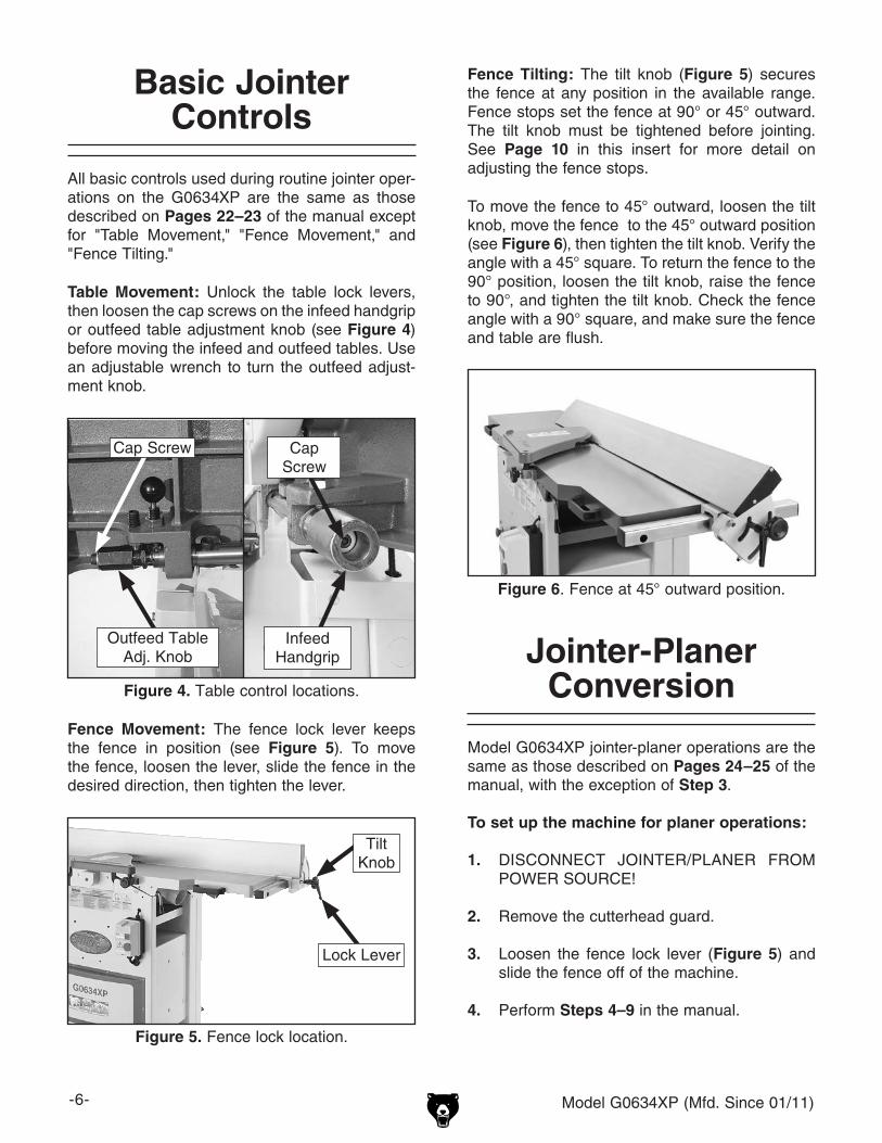
Table Movement: Unlock the table lock levers, then loosen the cap screws on the infeed handgrip or outfeed table adjustment knob (see Figure 4) before moving the infeed and outfeed tables. Use an adjustable wrench to turn the outfeed adjust-ment knob.
Figure 4. Table control locations.
Outfeed Table Adj. Knob
Infeed Handgrip
Cap Screw Cap Screw

Model G0634XP (Mfd. Since 01/11) -7-
Lubrication
Follow all lubrication instructions outlined on Pages 35–36 of the manual. Lubricate the G634XP fence with multi-purpose grease, as shown in Figures 7–8.
Figure 7. Inside fence lubrication locations.
The fence stops simplify the task of adjusting the fence to 45˚ and 90˚.
Tools Needed Qty45° Square ........................................................ 190° Square ........................................................ 1Sliding Bevel ...................................................... 1Wrench 10mm ................................................... 1Wrench 12mm ................................................... 1Hex Wrench 3mm .............................................. 1Hex Wrench 4mm .............................................. 1
To set the 90˚ fence stop:
1. Loosen the lock nut on the 90° fence stop screw shown in Figure 9, and loosen the fence tilt knob.
Setting Fence Stops
2. Place a 90° square against the table and fence, and adjust the stop screw so the fence is set exactly at 90°.
3. Tighten the lock nut.
Figure 9. Adjusting fence to 90°.
90˚Stop ScrewLock Nut
Figure 8. Outside fence lubrication location.
-8- Model G0634XP (Mfd. Since 01/11)
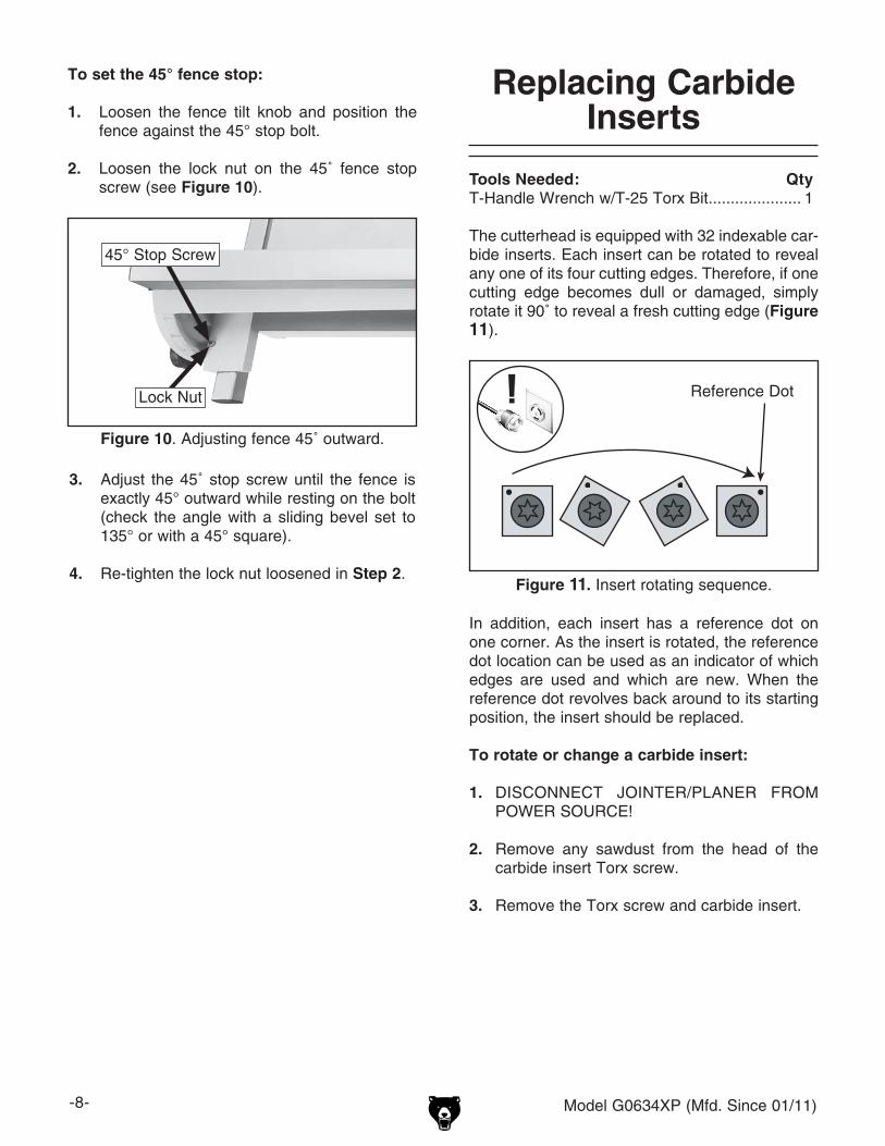
To set the 45° fence stop:
1. Loosen the fence tilt knob and position the fence against the 45° stop bolt.
2. Loosen the lock nut on the 45˚ fence stop screw (see Figure 10).
Figure 10. Adjusting fence 45˚ outward.
Lock Nut
3. Adjust the 45˚ stop screw until the fence is exactly 45° outward while resting on the bolt (check the angle with a sliding bevel set to 135° or with a 45° square).
4. Re-tighten the lock nut loosened in Step 2.
45° Stop Screw
Replacing Carbide Inserts
Tools Needed: QtyT-Handle Wrench w/T-25 Torx Bit ..................... 1
The cutterhead is equipped with 32 indexable car-bide inserts. Each insert can be rotated to reveal any one of its four cutting edges. Therefore, if one cutting edge becomes dull or damaged, simply rotate it 90˚ to reveal a fresh cutting edge (Figure 11).
Figure 11. Insert rotating sequence.
Reference Dot
In addition, each insert has a reference dot on one corner. As the insert is rotated, the reference dot location can be used as an indicator of which edges are used and which are new. When the reference dot revolves back around to its starting position, the insert should be replaced.
To rotate or change a carbide insert:
1. DISCONNECT JOINTER/PLANER FROM POWER SOURCE!
2. Remove any sawdust from the head of the carbide insert Torx screw.
3. Remove the Torx screw and carbide insert.

Model G0634XP (Mfd. Since 01/11) -9-
4. Clean all dust and dirt off the insert and the cutterhead pocket from which the insert was removed, and replace the insert so a fresh, sharp edge is facing outward.
Note: Proper cleaning is critical to achieving a smooth finish. Dirt or dust trapped between the insert and cutterhead will slightly raise the insert, and make noticeable marks on your-workpieces the next time you plane.
5. Lubricate the Torx screw threads with a light machine oil, wipe the excess oil off the threads, and torque the Torx screw to 55 inch/pounds.
Note: Do not overlubricate. Excess oil may squeeze between the insert and cutterhead, thereby lifting the insert slightly and affecting workpiece finishes.
T24736—Carbide Inserts (10 Pk) for G0634XPThese indexable carbide inserts can be rotated to provide four factory sharp edges before replace-ment. Size: 15 x 15 x 2.5mm.
Accessories
Figure 12. T24736 Carbide Inserts.

-10- Model G0634XP (Mfd. Since 01/11)
Stand Assembly Parts Breakdown
544
1-1
1-2
3-1
1
4
2 802
808
811
810
REF PART # DESCRIPTION REF PART # DESCRIPTION1 P0634XP001 FRAME 5 P0634XP005 SIDE OPENING COVER1-1 P0634XP001-1 HINGE SHAFT BRACKET RIGHT 44 P0634XP044 HEX WRENCH 3/321-2 P0634XP001-2 HINGE SHAFT BRACKET LEFT 802 P0634XP802 MACHINE ID LABEL2 P0634XP002 DRIVE SHAFT COVER 808 PPAINT-24 PB WHITE TOUCH-UP PAINT3-1 P0634XP003-1 COVER 810 P0634XP810 MODEL # LABEL4 P0634XP004 DOOR 811 PLABEL-75 POLAR BEAR LOGO 2-1/2 X 9-1/2
Table Assembly Parts Breakdown
102
101
135-4135-5
104-2
115V2
REF PART # DESCRIPTION REF PART # DESCRIPTION101 P0634XP101 INFEED TABLE 115V2 P0634XP115V2 CUTTERHEAD GUARD BRACKET V2.04.16102 P0634XP102 OUTFEED TABLE 135-4 P0634XP135-4 JOINTER DP L-BRACKET104-2 P0634XP104-2 JOINTER DUST PORT 4" 135-5 P0634XP135-5 JDP PLATE

Model G0634XP (Mfd. Since 01/11) -11-
Cutterhead Parts Breakdown
225
204-1A
215-6
215
215-7
201-3
201-4
201
201-1201-2V2208V2
229V2
REF PART # DESCRIPTION REF PART # DESCRIPTION201 P0634Z201V2 SPIRAL CUTTERHEAD 12" 10-32 V2.09.09 208V2 P0634XP208V2 COVER V2.04.16201-1 P0634XP201-1 INDEXABLE CUTTER 15 X 15 X 2.5 215 P0634XP215 DUST CHUTE201-2V2 P0634XP201-2V2 FLAT HD TORX T25 10-32 X 1/2 V2.01.11 215-6 P0634XP215-6 PLANER DP L-BRACKET201-3 P0634Z201-3 TORX T-HANDLE WRENCH 1/4 215-7 P0634XP215-7 PDP PLATE201-4 P0634Z201-4 TORX BIT T-25 1/4" HEX SHANK 225 P0634XP225 GUARD204-1A P0634XP204-1A PLANER DUST PORT 4" 229V2 P0634XP229V2 SET SCREW 1/4-20 X 3/4 CONE-PT V2.04.16

-12- Model G0634XP (Mfd. Since 01/11)
Fence/Guard Parts Breakdown
602
601
600
603
604
619
625
626
615 612
610
605
605
607
620618
616
617 627
624
623
621
614613
612611
606
621
609
640641
608
608-1
610-1610-2
639607
636
631V2636
643
635634
645644
642
634
702
701
707705
703704
710
REF PART # DESCRIPTION REF PART # DESCRIPTION600 P0634XP600 COMPLETE FENCE ASSEMBLY 618 PW07 FLAT WASHER 5/16601 P0634XP601 FENCE 619 P0634XP619 FENCE ANGLE SUPPORT602 P0634XP602 FENCE FIXED PLATE 620 PCAP03 CAP SCREW 5/16-18 X 1603 P0634XP603 LEFT FENCE CAP 621 P0634XP621 STUD-UDE 3/8-16 X 2-1/2 1/2 / 3/4RH604 P0634XP604 RIGHT FENCE CAP 623 PN05 HEX NUT 1/4-20605 PHTEK23 TAP SCREW #10 X 1/2 624 PSS10 SET SCREW 1/4-20 X 5/8606 P0634XP606 REAR GUARD HINGE 625 P0634XP625 FENCE SUPPORT607 PS17M PHLP HD SCR M4-.7 X 6 626 P0634XP626 FENCE SUPPORT PLATE608 P0634XP608 REAR GUARD CONNECTOR 627 PFH01 FLAT HD SCR 10-24 X 3/8608-1 P0634XP608-1 REAR GUARD LINK 631V2 P0634XP631V2 FENCE RAIL W/BRACE HOLES V2.04.11609 P0634XP609 FENCE ANGLE SCALE 634 PLW04 LOCK WASHER 3/8610 P0634XP610 FENCE LOCK LEVER 635 PN08 HEX NUT 3/8-16610-1 P0634XP610-1 COMPRESSION SPRING 636 P0634XP636 FENCE RAIL END CAP610-2 P0634XP610-2 PHLP SHOULDER SCR M5-.8 X 15 639 P0634XP639 FIXED PLATE611 P0634XP611 FENCE LOCK LEVER SCREW 640 P0634XP640 PLASTIC PROTECTION SHOE612 PW02 FLAT WASHER 3/8 641 PSS29 SET SCREW 10-24 X 1/4613 PLN01 LOCK NUT 3/8-16 642 P0634XP642 FENCE RAIL BRACE614 PW02 FLAT WASHER 3/8 643 PB16 HEX BOLT 3/8-16 X 1-1/2615 P0634XP615 ANGLE ADJUSTMENT KNOB 3/8 644 PW06 FLAT WASHER 1/4616 PN02 HEX NUT 5/16-18 645 PB19 HEX BOLT 1/4-20 X 1/2617 PSS01 SET SCREW 5/16-18 X 1

MODEL G0633/G0634JOINTER/PLANER
COMBINATION MACHINEOWNER'S MANUAL
COPYRIGHT © APRIL, 2007 BY GRIZZLY INDUSTRIAL, INC., REVISED AUGUST, 2007 (BL)WARNING: NO PORTION OF THIS MANUAL MAY BE REPRODUCED IN ANY SHAPE
OR FORM WITHOUT THE WRITTEN APPROVAL OF GRIZZLY INDUSTRIAL, INC. #BL8977 PRINTED IN TAIWAN

This manual provides critical safety instructions on the proper setup, operation, maintenance, and service of this machine/tool. Save this document, refer to it often, and use it to instruct other operators.
Failure to read, understand and follow the instructions in this manual may result in fire or serious personal injury—including amputation, electrocution, or death.
The owner of this machine/tool is solely responsible for its safe use. This responsibility includes but is not limited to proper installation in a safe environment, personnel training and usage authorization, proper inspection and maintenance, manual availability and compre-hension, application of safety devices, cutting/sanding/grinding tool integrity, and the usage of personal protective equipment.
The manufacturer will not be held liable for injury or property damage from negligence, improper training, machine modifications or misuse.
Some dust created by power sanding, sawing, grinding, drilling, and other construction activities contains chemicals known to the State of California to cause cancer, birth defects or other reproductive harm. Some examples of these chemicals are:
• Lead from lead-based paints.• Crystalline silica from bricks, cement and other masonry products.• Arsenic and chromium from chemically-treated lumber.
Your risk from these exposures varies, depending on how often you do this type of work. To reduce your exposure to these chemicals: Work in a well ventilated area, and work with approved safety equip-ment, such as those dust masks that are specially designed to filter out microscopic particles.

Table of ContentsINTRODUCTION ............................................... 2
Foreword ........................................................ 2Contact Info.................................................... 2G0633 Machine Data Sheet .......................... 3G0634 Machine Data Sheet .......................... 5Identification ................................................... 7
SECTION 1: SAFETY ....................................... 8Safety Instructions for Machinery .................. 8Additional Safety Instructions for Jointers ... 10Additional Safety Instructions for Planers .... 11
SECTION 2: CIRCUIT REQUIREMENTS ...... 12220V Operation ............................................ 12
SECTION 3: SET UP ...................................... 13Set Up Safety ............................................... 13Items Needed for Setup ............................... 13Unpacking .................................................... 13Inventory ...................................................... 14Hardware Recognition Chart ....................... 15Clean Up ...................................................... 16Site Considerations ...................................... 16Moving & Placing Base Unit ........................ 17Setting Outfeed Table Height ...................... 18Cutterhead Guard ........................................ 18Knife Setting Gauge ..................................... 19Dust Collection ............................................. 19Test Run ...................................................... 20Recommended Adjustments ........................ 21Tighten V-Belts ............................................ 21
SECTION 4: OPERATIONS ........................... 22Operation Safety .......................................... 22Basic Jointer Controls .................................. 22Basic Planer Controls .................................. 24Jointer-Planer Conversion ........................... 24Stock Inspection and Requirements ............ 26Squaring Stock............................................. 27Surface Planing............................................ 28Edge Jointing ............................................... 29Bevel Cutting................................................ 30Basic Planer Operation ................................ 31
SECTION 5: ACCESSORIES ......................... 32
SECTION 6: MAINTENANCE ......................... 34Schedule ...................................................... 34Cleaning ....................................................... 34V-Belts ......................................................... 34Lubrication ................................................... 35
SECTION 7: SERVICE ................................... 37Troubleshooting ........................................... 37Checking/Adjusting Jointer Table Parallelism ..39Inspecting Knives (G0633 Only) .................. 42Adjusting/Replacing Knives (G0633) ........... 43Replacing Carbide Inserts (G0634) ............. 45Calibrating Depth Scale ............................... 46Pulley Alignment .......................................... 46Setting Fence Stops .................................... 47Adjusting Table Lock Levers........................ 48Adjusting Gibs .............................................. 49Planer Table Parallelism .............................. 50Spring Tension ............................................. 51Anti-Kickback Fingers .................................. 52Electrical Components ................................. 53Wiring Diagram ............................................ 54Stand Assembly Parts Breakdown .............. 55Stand Parts List ........................................... 56Table Assembly Parts Breakdown & List..... 57Cutterhead & Motor Breakdown .................. 58Cutterhead & Motor Parts List ..................... 59Drive Assembly Breakdown & List ............... 60Planer Table Breakdown & List ................... 61Limit Switch Breakdown & List .................... 62Fence/Guard Breakdown & List ................... 63Fence/Guard List ......................................... 64Safety Labels and Cosmetic Parts .............. 65
WARRANTY AND RETURNS ........................ 66

-2- G0633/G0634 Jointer/Planer Combo Machine
INTRODUCTION
Foreword
We are proud to offer the Model G0633/G0634 Jointer/Planer Combination Machine. This machine is part of a growing Grizzly family of fine woodworking machinery. When used according to the guidelines set forth in this manual, you can expect years of trouble-free, enjoyable operation and proof of Grizzly’s commitment to customer satisfaction.
The specifications, drawings, and photographs illustrated in this manual represent the Model G0633/G0634 when the manual was prepared. However, owing to Grizzly’s policy of continuous improvement, changes may be made at any time with no obligation on the part of Grizzly.
For your convenience, we always keep current Grizzly manuals available on our website at www.grizzly.com. Any updates to your machine will be reflected in these manuals as soon as they are complete. Visit our site often to check for the lat-est updates to this manual!
Contact Info
If you have any comments regarding this manual, please write to us at the address below:
Grizzly Industrial, Inc.C/O Technical Documentation Manager
P.O. Box 2069Bellingham, WA 98227-2069Email: [email protected]
We stand behind our machines. If you have any service questions or parts requests, please call or write us at the location listed below.
Grizzly Industrial, Inc.1203 Lycoming Mall Circle
Muncy, PA 17756Phone: (570) 546-9663
Fax: (800) 438-5901E-Mail: [email protected] Site: http://www.grizzly.com

G0633/G0634 Jointer/Planer Combo Machine -3-
MODEL G0633JOINTER/PLANER COMBINATION MACHINE
Customer Service #: (570) 546-9663 • To Order Call: (800) 523-4777 • Fax #: (800) 438-5901
MACHINE DATA SHEET
Product Dimensions:
Weight .............................................................................................................................................................672 lbs. Length/Width/Height .............................................................................................................. 41-1/4 x 59-5/8 x 45 in. Foot Print (Length/Width) ...................................................................................................................... 19-1/2 x 26 in.
Shipping Dimensions: Type .......................................................................................................................................................... Wood Crate Content ............................................................................................................................................................Machine Weight ..............................................................................................................................................................767 lbs. Length/Width/Height ..........................................................................................................34-1/4 x 62-1/2 x 44-3/8 in.
Electrical: Switch ......................................................................................................Magnetic with Thermal Overload Protection Switch Voltage .....................................................................................................................................................220V Cord Length ......................................................................................................................................................... 10 ft. Cord Gauge .................................................................................................................................................. 12 gauge Recommended Breaker Size ........................................................................................................................... 30 amp Plug ..........................................................................................................................................................................No
Motors: Main
Type ................................................................................................................. TEFC Capacitor Start Induction Horsepower ................................................................................................................................................ 5 HP Voltage .......................................................................................................................................................220V Phase ....................................................................................................................................................... Single Amps ............................................................................................................................................................25A Speed ................................................................................................................................................ 3450 RPM Cycle .........................................................................................................................................................60 Hz Number Of Speeds .......................................................................................................................................... 1 Power Transfer .............................................................................................................................. Twin V-Belts Bearings ...................................................................................................................... Shielded and Lubricated
Main Specifications: Fence Information
Fence Length ...................................................................................................................................... 39-3/8 in. Fence Height ......................................................................................................................................... 5-7/8 in. Fence Stops ............................................................................................................................... 45 and 90 deg. Cutting Capacities (Jointer)
Bevel Jointing ..................................................................................................................................... 0-45 deg. Maximum Width of Cut ............................................................................................................................. 12 in. Maximum Depth of Cut ............................................................................................................................ 1/8 in. Number of Cuts Per Minute ..................................................................................................................... 15102 Minimum Stock Length ......................................................................................................................... 5-5/8 in.
Model G0633 Page 1 of 2

-4- G0633/G0634 Jointer/Planer Combo Machine
Cutting Capacities (Planer)
Maximum Width of Cut ....................................................................................................................... 11-3/4 in. Maximum Depth of Cut Planing Full Width .............................................................................................. 1/8 in. Maximum Depth of Cut Planing 6" Wide Board ..................................................................................... 5/32 in. Number of Cuts Per Minute ..................................................................................................................... 15102 Number of Cuts Per Inch ............................................................................................................................... 57 Feed Speeds ..........................................................................................................................................22 FPM Minimum Stock Length ............................................................................................................................. 12 in. Maximum Stock Thickness ......................................................................................................................... 8 in.
Knife Information (Jointer)
Number of Knives ............................................................................................................................................ 3 Knife Type ...................................................................................................................................................HSS Knife Length. ............................................................................................................................................. 12 in. Knife Width. ................................................................................................................................................. 1 in. Knife Thickness. ....................................................................................................................................... 1/8 in. Knife Adjustment. .......................................................................................................Springs and Jack Screws
Cutterhead Information
Cutterhead Type ..........................................................................................................................3 HSS Knives Cutterhead Diameter ............................................................................................................................. 3-1/8 in. Cutterhead Speed ............................................................................................................................. 5034 RPM
Table Information (Jointer)
Table Length ....................................................................................................................................... 59-1/2 in. Table Width ............................................................................................................................................... 14 in. Floor To Table Height ......................................................................................................................... 35-1/2 in.
Table Information (Planer)
Table Length ....................................................................................................................................... 23-1/8 in. Table Width ......................................................................................................................................... 12-1/4 in. Table Thickness .................................................................................................................................... 1-5/8 in. Floor To Table Height ......................................................................................................................... 32-1/2 in.
Construction
Body Assembly Construction ...............................................................................................................Cast Iron Cutterhead Assembly Construction ........................................................................................................... Steel Infeed Roller Construction ......................................................................................................................... Steel Outfeed Roller Construction ....................................................................................................................... Steel Stand Construction ..................................................................................................Heavy Gauge Sheet Metal Table Construction ...............................................................................................................................Cast Iron Paint. ......................................................................................................................................... Powder Coated
Other Infomation
Dust Port Size ............................................................................................................................................. 4 in. Number of Dust Ports ...................................................................................................................................... 2 Measurement Scale (Jointer) .......................................................................................................................Inch Measurement Scale (Planer) ............................................................................................................Inch/Metric
Other Specifications:
Country Of Origin ..............................................................................................................................................Taiwan Warranty .............................................................................................................................................................1 Year Serial Number Location ...............................................................................................ID Label on Front of the Stand Features: Quick Release Fence Flip Up Tables and Change Lever Simplify Jointer-Planer Conversion Jointer Tables Lock Into Raised Position for Planer Operation; Hand Knobs Release Tables Cast Iron Infeed and Outfeed Tables
Model G0633 Page 2 of 2
G0633/G0634 Jointer/Planer Combo Machine -5-
model G0634 JoINTeR/PlANeR ComBINATIoN mACHINe w/sPIRAl CuTTeRHeAd
Customer Service #: (570) 546-9663 • To Order Call: (800) 523-4777 • Fax #: (800) 438-5901
mACHINe dATA sHeeT
Product Dimensions:
Weight .............................................................................................................................................................672 lbs. Length/Width/Height .............................................................................................................. 41-1/4 x 59-5/8 x 45 in. Foot Print (Length/Width) ...................................................................................................................... 19-1/2 x 26 in.
Shipping Dimensions: Type .......................................................................................................................................................... Wood Crate Content ............................................................................................................................................................Machine Weight ..............................................................................................................................................................767 lbs. Length/Width/Height ..........................................................................................................34-1/4 x 62-1/2 x 44-3/8 in.
Electrical: Switch ......................................................................................................Magnetic with Thermal Overload Protection Switch Voltage .....................................................................................................................................................220V Cord Length ......................................................................................................................................................... 10 ft. Cord Gauge .................................................................................................................................................. 12 gauge Recommended Breaker Size ........................................................................................................................... 30 amp Plug ..........................................................................................................................................................................No
Motors: Main
Type ................................................................................................................. TEFC Capacitor Start Induction Horsepower ................................................................................................................................................ 5 HP Voltage .......................................................................................................................................................220V Phase ....................................................................................................................................................... Single Amps ............................................................................................................................................................25A Speed ................................................................................................................................................ 3450 RPM Cycle .........................................................................................................................................................60 Hz Number Of Speeds .......................................................................................................................................... 1 Power Transfer .............................................................................................................................. Twin V-Belts Bearings ...................................................................................................................... Shielded and Lubricated
Main Specifications: Fence Information
Fence Length ...................................................................................................................................... 39-3/8 in. Fence Height ......................................................................................................................................... 5-7/8 in. Fence Stops ............................................................................................................................... 45 and 90 deg. Cutting Capacities (Jointer)
Bevel Jointing ..................................................................................................................................... 0-45 deg. Maximum Width of Cut ............................................................................................................................. 12 in. Maximum Depth of Cut ............................................................................................................................ 1/8 in. Number of Cuts Per Minute ..................................................................................................................... 20136 Minimum Stock Length ......................................................................................................................... 5-5/8 in.
Model G0634 Page 1 of 2

-6- G0633/G0634 Jointer/Planer Combo Machine
Cutting Capacities (Planer)
Maximum Width of Cut ............................................................................................................................. 12 in. Maximum Depth of Cut Planing Full Width .............................................................................................. 1/8 in. Maximum Depth of Cut Planing 6" Wide Board ..................................................................................... 5/32 in. Number of Cuts Per Minute .................................................................................................................... 20,136 Number of Cuts Per Inch ............................................................................................................................... 75 Feed Speeds ..........................................................................................................................................22 FPM Minimum Stock Length ............................................................................................................................. 12 in. Minimum Stock Thickness ....................................................................................................................... 1/4 in. Maximum Stock Thickness ......................................................................................................................... 8 in.
Cutterhead Information
Cutterhead Type ....................................................................................................................................... Spiral Cutterhead Diameter ............................................................................................................................. 3-1/8 in. Number of Cutter Spirals ................................................................................................................................. 4 Number of Indexable Cutters ......................................................................................................................... 56 Cutter Insert Type ....................................................................................................4 Sided Indexable Carbide Cutter Insert Length ................................................................................................................................ 14 mm Cutter Insert Width .................................................................................................................................. 14 mm Cutter Insert Thickness ............................................................................................................................. 2 mm Cutterhead Speed ............................................................................................................................. 5034 RPM
Table Information (Jointer)
Table Length ....................................................................................................................................... 59-1/2 in. Table Width ............................................................................................................................................... 14 in. Floor To Table Height ......................................................................................................................... 35-1/2 in.
Table Information (Planer)
Table Length ....................................................................................................................................... 23-1/8 in. Table Width ......................................................................................................................................... 12-1/4 in. Table Thickness .................................................................................................................................... 1-5/8 in. Floor To Table Height ......................................................................................................................... 32-1/2 in.
Construction
Body Assembly Construction ...............................................................................................................Cast Iron Cutterhead Assembly Construction ........................................................................................................... Steel Infeed Roller Construction ......................................................................................................................... Steel Outfeed Roller Construction ....................................................................................................................... Steel Stand Construction ..................................................................................................Heavy Gauge Sheet Metal Table Construction ...............................................................................................................................Cast Iron Paint. ......................................................................................................................................... Powder Coated
Other Infomation
Dust Port Size ............................................................................................................................................. 4 in. Number of Dust Ports ...................................................................................................................................... 2 Measurement Scale (Jointer) .......................................................................................................................Inch Measurement Scale (Planer) ............................................................................................................Inch/Metric
Other Specifications:
Country Of Origin ..............................................................................................................................................Taiwan Warranty .............................................................................................................................................................1 Year Serial Number Location ...............................................................................................ID Label on Front of the Stand Features: Quick Release Fence Flip Up Tables and Change Lever Simplify Jointer-Planer Conversion Jointer Tables Lock Into Raised Position for Planer Operation; Hand Knobs Release Tables Cast Iron Infeed and Outfeed Tables Dual 4" Dust Ports
Model G0634 Page 2 of 2

G0633/G0634 Jointer/Planer Combo Machine -7-
Figure 1. G0634 identification and controls.
A. Outfeed TableB. FenceC. Cutterhead GuardD. Fence Height KnobsE. Quick Release KnobsF. Tilt LockG. Fence Lock LeverH. Fence Adjustment KnobI. Infeed Table Lock KnobJ. Infeed HandgripK. Infeed TableL. Jointer Dust PortM. Planer Table
Identification
N. Infeed Table Lock LeverO. Jointer Depth ScaleP. Magnetic SwitchQ. Emergency Off ButtonR. Change Lever S. Planer Table LockT. Planer Dust PortU. Planer Table Height HandwheelV. Planer Table Height ScaleW Outfeed Table Adjustment KnobX. Outfeed Table Lock Knob
AD
E
F
G H
K
M
N
O
Q
V
USR
T
BC
WX
IJ
P
L

-8- G0633/G0634 Jointer/Planer Combo Machine
ELECTRICAL EQUIPMENT INJURY RISKS. You can be shocked, burned, or killed by touching live electrical components or improperly grounded machinery. To reduce this risk, only allow qualified service personnel to do electrical installation or repair work, and always disconnect power before accessing or exposing electrical equipment.
DISCONNECT POWER FIRST. Always discon-nect machine from power supply BEFORE making adjustments, changing tooling, or servicing machine. This prevents an injury risk from unintended startup or contact with live electrical components.
EYE PROTECTION. Always wear ANSI-approved safety glasses or a face shield when operating or observing machinery to reduce the risk of eye injury or blindness from flying particles. Everyday eyeglasses are NOT approved safety glasses.
OWNER’S MANUAL. Read and understand this owner’s manual BEFORE using machine.
TRAINED OPERATORS ONLY. Untrained oper-ators have a higher risk of being hurt or killed. Only allow trained/supervised people to use this machine. When machine is not being used, dis-connect power, remove switch keys, or lock-out machine to prevent unauthorized use—especially around children. Make your workshop kid proof!
DANGEROUS ENVIRONMENTS. Do not use machinery in areas that are wet, cluttered, or have poor lighting. Operating machinery in these areas greatly increases the risk of accidents and injury.
MENTAL ALERTNESS REQUIRED. Full mental alertness is required for safe operation of machin-ery. Never operate under the influence of drugs or alcohol, when tired, or when distracted.
For Your Own Safety, Read Instruction Manual Before Operating This Machine
The purpose of safety symbols is to attract your attention to possible hazardous conditions. This manual uses a series of symbols and signal words intended to convey the level of impor-tance of the safety messages. The progression of symbols is described below. Remember that safety messages by themselves do not eliminate danger and are not a substitute for proper accident prevention measures. Always use common sense and good judgment.
Indicates a potentially hazardous situation which, if not avoided, MAY result in minor or moderate injury. It may also be used to alert against unsafe practices.
Indicates a potentially hazardous situation which, if not avoided, COULD result in death or serious injury.
Indicates an imminently hazardous situation which, if not avoided, WILL result in death or serious injury.
This symbol is used to alert the user to useful information about proper operation of the machine.NOTICE
Safety Instructions for Machinery
SECTION 1: SAFETY

G0633/G0634 Jointer/Planer Combo Machine -9-
WEARING PROPER APPAREL. Do not wear clothing, apparel or jewelry that can become entangled in moving parts. Always tie back or cover long hair. Wear non-slip footwear to reduce risk of slipping and losing control or accidentally contacting cutting tool or moving parts.
HAZARDOUS DUST. Dust created by machinery operations may cause cancer, birth defects, or long-term respiratory damage. Be aware of dust hazards associated with each workpiece mate-rial. Always wear a NIOSH-approved respirator to reduce your risk.
HEARING PROTECTION. Always wear hear-ing protection when operating or observing loud machinery. Extended exposure to this noise without hearing protection can cause permanent hearing loss.
REMOVE ADJUSTING TOOLS. Tools left on machinery can become dangerous projectiles upon startup. Never leave chuck keys, wrenches, or any other tools on machine. Always verify removal before starting!
USE CORRECT TOOL FOR THE JOB. Only use this tool for its intended purpose—do not force it or an attachment to do a job for which it was not designed. Never make unapproved modifica-tions—modifying tool or using it differently than intended may result in malfunction or mechanical failure that can lead to personal injury or death!
AWKWARD POSITIONS. Keep proper footing and balance at all times when operating machine. Do not overreach! Avoid awkward hand positions that make workpiece control difficult or increase the risk of accidental injury.
CHILDREN & BYSTANDERS. Keep children and bystanders at a safe distance from the work area.Stop using machine if they become a distraction.
GUARDS & COVERS. Guards and covers reduce accidental contact with moving parts or flying debris. Make sure they are properly installed, undamaged, and working correctly BEFORE operating machine.
FORCING MACHINERY. Do not force machine. It will do the job safer and better at the rate for which it was designed.
NEVER STAND ON MACHINE. Serious injury may occur if machine is tipped or if the cutting tool is unintentionally contacted.
STABLE MACHINE. Unexpected movement dur-ing operation greatly increases risk of injury or loss of control. Before starting, verify machine is stable and mobile base (if used) is locked.
USE RECOMMENDED ACCESSORIES. Consult this owner’s manual or the manufacturer for rec-ommended accessories. Using improper acces-sories will increase the risk of serious injury.
UNATTENDED OPERATION. To reduce the risk of accidental injury, turn machine OFF and ensure all moving parts completely stop before walking away. Never leave machine running while unattended.
MAINTAIN WITH CARE. Follow all maintenance instructions and lubrication schedules to keep machine in good working condition. A machine that is improperly maintained could malfunction, leading to serious personal injury or death.
DAMAGED PARTS. Regularly inspect machine for damaged, loose, or mis-adjusted parts—or any condition that could affect safe operation. Immediately repair/replace BEFORE operating machine. For your own safety, DO NOT operate machine with damaged parts!
MAINTAIN POWER CORDS. When disconnect-ing cord-connected machines from power, grab and pull the plug—NOT the cord. Pulling the cord may damage the wires inside. Do not handle cord/plug with wet hands. Avoid cord damage by keeping it away from heated surfaces, high traffic areas, harsh chemicals, and wet/damp locations.
EXPERIENCING DIFFICULTIES. If at any time you experience difficulties performing the intend-ed operation, stop using the machine! Contact our Technical Support at (570) 546-9663.

-10- G0633/G0634 Jointer/Planer Combo Machine
Additional Safety for Jointers
KICKBACK. Occurs when workpiece is ejected from machine at a high rate of speed. Kickback injuries occur from getting struck by workpiece or hands being pulled into cutterhead. To reduce the risk of kickback, only use proper workpieces, safe feeding techniques, and proper machine setup or maintenance.
GUARD REMOVAL. Operating jointer without guards unnecessarily exposes operator to knives/inserts and other hazardous moving parts. Except when rabbeting, never operate jointer or allow it to be connected to power if any guards are removed. Turn jointer OFF and disconnect power before clearing any shavings or sawdust from around cut-terhead. After rabbeting or maintenance is com-plete, immediately replace all guards and ensure they are properly installed/adjusted before resum-ing regular operations.
DULL OR DAMAGED KNIVES/INSERTS. Dull or damaged knives/inserts increase risk of kickback and cause poor workpiece finish. Only use sharp, undamaged knives/inserts.
OUTFEED TABLE ALIGNMENT. Setting outfeed table too high can cause workpiece to hit table or get stuck while feeding. Setting outfeed table too low may cause workpiece to rock or shift while feeding. Both of these results will increase risk of kickback. Always keep outfeed table even with knives/inserts at highest point during rotation.
INSPECTING STOCK. Impact injuries or kick-back may result from using improper workpieces. Thoroughly inspect and prepare workpiece before cutting. Verify workpiece is free of nails, staples, loose knots or other foreign material. Warped workpieces must be surface planed first with cupped side facing down.
MAXIMUM CUTTING DEPTH. To reduce risk of kickback, never cut deeper than 1⁄8" per pass.
GRAIN DIRECTION. Jointing against the grain or end grain can increase risk of kickback. It also requires more cutting force, which produces chat-ter or excessive chip out. Always joint or surface plane WITH the grain.
CUTTING LIMITATIONS. Cutting workpieces that do not meet minimum dimension requirements can result in kickback or accidental contact with cutter-head. Never perform jointing, planing, or rabbeting cuts on pieces smaller than 8" long, 3⁄4" wide, or 1⁄4" thick.
PUSH BLOCKS. Push blocks reduce risk of acci-dental cutterhead contact with hands. Always use push blocks when planing materials less than 3" high or wide. Never pass your hands directly over cutterhead without a push block.
WORKPIECE SUPPORT. Poor workpiece sup-port or loss of workpiece control while feeding will increase risk of kickback or accidental contact with cutterhead. Support workpiece with fence continuously during operation. Support long stock with auxiliary tables if necessary.
FEED WORKPIECE PROPERLY. Kickback or accidental cutterhead contact may result if work-piece is fed into cutterhead the wrong way. Allow cutterhead to reach full speed before feeding. Never start jointer with workpiece touching cutter-head. Always feed workpiece from infeed side to outfeed side without stopping until cut is complete. Never move workpiece backwards while feeding.
SECURE KNIVES/INSERTS. Loose knives or improperly set inserts can be thrown from cutter-head with dangerous force. Always verify knives/inserts are secure and properly adjusted before operation. Straight knives should never project more than 1⁄8" (0.125") from cutterhead body.
Serious cuts, amputation, entanglement, or death can occur from contact with rotating cutterhead or other moving components! Flying chips from cutting operations can cause blindness or eye injuries. Workpieces or inserts/knives thrown by cutterhead (kickback) can strike nearby operator or bystanders with deadly force. To reduce the risk of serious personal injury from these hazards, operator and bystanders MUST completely heed the hazards and warnings below.

G0633/G0634 Jointer/Planer Combo Machine -11-
Additional Safety for Planers
Amputation, serious cuts, entanglement, or death can occur from contact with rotating cutterhead or other moving parts! Flying chips can cause blindness or eye injuries. Workpieces or knives thrown by cutterhead can strike nearby operator or bystanders with deadly force. To reduce the risk of these hazards, operator and bystanders MUST completely heed hazards and warnings below.
PLANING CORRECT MATERIAL. Only plane natural wood stock with this planer. DO NOT plane MDF, OSB, plywood, laminates or other synthetic materials that can break up inside the planer and be ejected towards the operator.
LOOKING INSIDE PLANER. Wood chips fly around inside the planer at a high rate of speed during operation. To avoid injury from flying mate-rial, DO NOT look inside planer during operation.
CUTTING LIMITATIONS. To reduce the risk of kickback hazards or damage to the machine, do not exceed the maximum depth of cut or minimum board length and thickness found in the Data Sheet. Only feed one board at a time.
INFEED ROLLER CLEARANCE. The infeed roller is designed to pull material into the spinning cutterhead. To reduce the risk of entanglement, keep hands, clothing, jewelry, and long hair away from the infeed roller during operation.
FEED WORKPIECE PROPERLY. To reduce the risk of kickback, never start planer with workpiece touching cutterhead. Allow cutterhead to reach full speed before feeding, and do not change feed speed during cutting operation.
WORKPIECE SUPPORT. To reduce the risk of kickback, always make sure workpiece can move completely across table without rocking or tipping. Use auxiliary support stands for long stock.
SECURE KNIVES/INSERTS. Loose knives or improperly set inserts can become dangerous projectiles or cause machine damage. Always verify knives/inserts are secure and properly adjusted before operation.
KICKBACK. Know how to reduce the risk of kick-back and kickback-related injuries. “Kickback” occurs during the operation when the workpiece is ejected from the machine at a high rate of speed. Kickback is commonly caused by poor workpiece selection, unsafe feeding techniques, or improper machine setup/maintenance. Kickback injuries typically occur as follows: (1) operator/bystanders are struck by the workpiece, resulting in impact injuries (i.e., blindness, broken bones, bruises, death); (2) operator’s hands are pulled into blade, resulting in amputation or severe lacerations.
AVOID CONTACT WITH MOVING PARTS. Never remove guards/covers or reach inside the planer during operation or while connected to power. You could be seriously injured if you accidentally touch the spinning cutterhead or get entangled in moving parts. If a workpiece becomes stuck or sawdust removal is necessary, turn planer OFF and disconnect power before clearing.
DULL/DAMAGED KNIVES/INSERTS. Only use sharp, undamaged knives/inserts. Dull or dam-aged knives/inserts increase the risk of kickback.
INSPECTING STOCK. To reduce the risk of kickback injuries or machine damage, thoroughly inspect and prepare the workpiece before cutting. Verify workpiece is free of nails, staples, loose knots or foreign material. Workpieces with minor warping should be jointed first or planed with the cupped side facing the table.
BODY PLACEMENT. Stand to one side of planer during the entire operation to avoid getting hit if kickback occurs.
GRAIN DIRECTION. Planing across the grain is hard on the planer and may cause kickback. Plane in the same direction or at a slight angle with the wood grain.

-12- G0633/G0634 Jointer/Planer Combo Machine
Serious personal injury could occur if you connect the machine to the power source before you have completed the set up pro-cess. DO NOT connect the machine to the power source until instructed to do so.
220V Operation GroundingIn the event of an electrical short, grounding reduces the risk of electric shock. The grounding wire in the power cord must be properly connected to the grounding prong on the plug; likewise, the outlet must be properly installed and grounded. All electrical connections must be made in accor-dance with local codes and ordinances.
Amperage DrawThe Model G0633/G0634 motor draws the follow-ing amps under maximum load:
Motor Draw at 220V...............................25 Amps
Circuit RequirementsWe recommend connecting your machine to a dedicated and grounded circuit that is rated for the amperage given below. Never replace a circuit breaker on an existing circuit with one of higher amperage without consulting a qualified electri-cian to ensure compliance with wiring codes. If you are unsure about the wiring codes in your area or you plan to connect your machine to a shared circuit, consult a qualified electrician.
220V Circuit ...........................................30 Amps
Plug/Receptacle TypeRecommended Plug/Receptacle ....NEMA L6-30
Electrocution or fire could result if this machine is not grounded correctly or if your electrical con-figuration does not com-ply with local and state codes. Ensure compliance by checking with a quali-fied electrician!
Extension CordsWe do not recommend the use of extension cords. Instead, arrange the placement of your equipment and the installed wiring to eliminate the need for extension cords.
If you find it absolutely necessary to use an exten-sion cord at 220V with your machine:
• Use at least a 10 gauge cord that does not exceed 50 feet in length!
• The extension cord must also contain a ground wire and plug pin.
• A qualified electrician MUST size cords over 50 feet long to prevent motor damage.
Grounding Prongis Hooked
Current Carrying Prongs
L6-30 GROUNDEDLOCKING
RECEPTACLE
L6-30LOCKING
PLUG
Figure 2. NEMA L6-30 plug and receptacle.
SECTION 2: CIRCUIT REQUIREMENTS

G0633/G0634 Jointer/Planer Combo Machine -13-
Wear safety glasses dur-ing the entire set up pro-cess!
This machine presents serious injury hazards to untrained users. Read through this entire manu-al to become familiar with the controls and opera-tions before starting the machine!
Set Up Safety
SECTION 3: SET UP
The Model G0633/G0634 is a heavy machine. DO NOT over-exert yourself while unpacking or mov-ing your machine—get assistance.
The following items are needed to complete the setup process, but are not included with your machine:
Description Qty• Safety Glasses (for each person) .............. 1• Power Lifting Equipment ............................ 1 • Lifting Straps (800 lb. Capacity, Optional) . 1• Dust Collection System .............................. 1• 4" Dust Hose (length as needed) ............... 1• 4" Hose Clamp ........................................... 1• Shop Rags for Cleaning .............As needed• Solvent Cleaner ...........................As needed
Items Needed for Setup
The Model G0633/G0634 was carefully packed when it left our warehouse. If you discover the machine is damaged after you have signed for delivery, please immediately call Customer Service at (570) 546-9663 for advice.
Save the containers and all packing materials for possible inspection by the carrier or its agent. Otherwise, filing a freight claim can be difficult.
When you are completely satisfied with the condi-tion of your shipment, inventory the contents.
Unpacking

-14- G0633/G0634 Jointer/Planer Combo Machine
Inventory
If any nonproprietary parts are missing (e.g. a nut or a washer), we will gladly replace them; or for the sake of expediency, replacements can be obtained at your local hardware store.
Figure 5. Spiral cutterhead hardware.
The following is a description of the main compo-nents shipped with your machine. Lay the compo-nents out to inventory them.
Note: If you can't find an item on this list, check the mounting location on the machine or examine the packaging materials carefully. Occasionally we pre-install certain components for shipping purposes.
Common Components (Figure 3 & 3) QtyA. Jointer/Planer Assembly (Not shown) ........ 1B. Push Blocks ................................................ 2C. Cutterhead Guard Assembly ...................... 1D. Hardware and Tools (Not Shown)
— Wrench 12/14 ......................................... 1— Hex Wrench 3mm .................................. 1
G0633 ONLY (Figure 4)E. Knife Setting Jig Hardware
— Knife Setting Gauge Feet ...................... 2— Knife Setting Gauge Rod ....................... 1— E-Clips 9mm .......................................... 2
F. Tools (Not Shown) — Wrench 8/10mm .................................... 1
G0634 ONLY (Figure 5)G. Spiral Cutterhead Hardware
— Indexable Carbide Inserts...................... 5— Flat Head Torx Screws M6-1 x 15 ........ 10—Torx Drivers T20 ..................................... 5—T-Handle Wrench 1/4" .............................. 1
Figure 3. Common components.
B
C
Figure 4. Knife gauge hardware.
E
G

G0633/G0634 Jointer/Planer Combo Machine -15-
5mm
Hardware Recognition Chart

-16- G0633/G0634 Jointer/Planer Combo Machine
Floor LoadRefer to the Machine Data Sheet for the weight and footprint specifications of your machine. Some residential floors may require additional reinforcement to support both the machine and operator.
Placement LocationConsider existing and anticipated needs, size of material to be processed through each machine, and space for auxiliary stands, work tables or other machinery when establishing a location for your new machine. See Figure 7 for the minimum working clearances.
The unpainted surfaces are coated with a waxy oil to prevent corrosion during shipment. Remove this protective coating with a solvent cleaner or citrus-based degreaser such as Grizzly’s G7895 Citrus Degreaser. To clean thoroughly, some parts must be removed. For optimum perfor-mance from your machine, clean all moving parts or sliding contact surfaces. Avoid chlo-rine-based solvents, such as brake parts cleaner that may damage painted surfaces. Always follow the manufacturer’s instructions when using any type of cleaning product.
Site ConsiderationsClean Up
Figure 7. Minimum working clearances.
4" Dust Collection Port
4" Dust Collection Port
Jointer Operation
Planer Operation
63"
411 /
2"
60"
411 /
2"
220V30A
220V30A
Children and visitors may be seriously injured if unsuper-vised around this machine. Lock entrances to the shop or disable start switch or power connection to prevent unsupervised use.
Figure 6. Grizzly citrus degreaser.
Many cleaning solvents are toxic if inhaled. Minimize your risk by only using these products in a well ventilated area.
Gasoline and petroleum products have low flash points and can explode or cause fire if used to clean machinery. DO NOT use these products to clean the machinery.
G7895—Grizzly Citrus DegreaserThis natural, citrus-based degreaser is a great solution for removing export grease, and it’s much safer to work around than nasty solvents.

G0633/G0634 Jointer/Planer Combo Machine -17-
Moving & Placing Base Unit
The Model G0633/G0634 is a heavy machine. Serious personal injury may occur if safe moving methods are not used. To be safe, get assistance and use power equipment to move the shipping crate and remove the machine from the crate.
Figure 10. Left rear lifting hole location.
Figure 9. Front and right rear lifting hole locations.
You can also attach hooks and lifting straps to the machine using the three lifting holes shown in Figures 9 & 10 with a forklift, hoist, or boom crane. If you choose this alternative, you must punch out the lifting strap holes—this will perma-nently alter your machine.
If you are unsure how to lift this machine, consult a qualified professional.
After setting the machine in place, remove the shipping brackets on both sides (Figure 9).
Unbolt the jointer/planer from the pallet, and use a forklift to lift the machine off the pallet and onto a suitable location as shown in Figure 8. Only lift the machine enough to clear the floor.
Figure 8. Lifting model G0633 with a forklift.
Brackets

-18- G0633/G0634 Jointer/Planer Combo Machine
Cutterhead Guard
To install the cutterhead guard:
1. Remove the shaft lock knob and insert the cutterhead guard shaft into the bracket hole as shown in Figure 13.
4. Test the guard by pulling it back and letting go. The rubber dot on the guard should hit the fence when the guard comes back.
—The guard should snap back over the cutterhead without dragging across the table.
—If the guard drags across the table, raise it until it won't drag, then tighten the shaft lock.
—If the guard does not snap back, remove it and repeat Steps 1–3.
2. Move the fence forward until it touches the cutterhead guard.
3. Thread the lock knob into the bracket so the threads fit into the shaft groove (Figure 13), and secure the guard into place. Adjust the guard and lock knob as needed so the guard fully covers the cutterhead.
Figure 13. Installing cutterhead guard.
Groove
Bracket
Figure 11. Cutterhead knife at top-dead-center.
Top DeadCenter
Setting Outfeed Table Height
4. Raise or lower the outfeed table until the knife (or carbide insert) just touches the straight-edge (Figure 12).
The outfeed table height MUST be level with the knives or carbide inserts when they are at top-dead-center. If the outfeed table is set too low, the workpiece will be tapered from front to back. If the outfeed table is set too high, the workpiece will hit the edge of the outfeed table during operation, increasing the chance of kickback.
To set the outfeed table height:
1. DISCONNECT THE JOINTER/PLANER FROM THE POWER SOURCE!
2. Place a straightedge on the outfeed table so it extends over the cutterhead.
3. Open the motor access panel and rotate the cutterhead pulley until one of the knives (or carbide inserts) is at top-dead-center (TDC), as illustrated in Figure 11.
Figure 12. Using a straightedge to align outfeed table height with knife at TDC.
Straightedge
Outfeed Infeed

G0633/G0634 Jointer/Planer Combo Machine -19-
Figure 14. Knife setting gauge assembly.
Assemble the knife setting gauge using the knife setting gauge rod, feet and 9mm e-clips as shown in Figure 14.
Knife Setting Gauge
Figure 15. Dust hose attached to jointer dust port.
Dust Collection
DO NOT operate the Model G0633/G0634 without an adequate dust collection system. This machine creates substantial amounts of wood dust while operating. Failure to use a dust collection system can result in short and long-term respiratory illness.
Recommended CFM at Each Dust Port: 400 Do not confuse this CFM recommendation with the rating of the dust collector. To determine the CFM at the dust port, you must consider these variables: (1) CFM rating of the dust col-lector, (2) hose type and length between the dust collector and the machine, (3) number of branches or wyes, and (4) amount of other open lines throughout the system. Explaining how to calculate these variables is beyond the scope of this manual. Consult an expert or pur-chase a good dust collection "how-to" book.
To connect a dust collection hose:
1. Fit the 4" dust hose over the jointer dust port, (see Figure 15), or over the planer dust port (see Figure 16), depending upon which operation mode is setup, and secure in place with a hose clamp.
2. Tug the hose to make sure it does not come off.
Note: A tight fit is necessary for proper per-formance.
Figure 16. Dust hose attached to planer dust port.

-20- G0633/G0634 Jointer/Planer Combo Machine
Test Run
Once the assembly is complete, test run your machine to make sure it runs properly and is ready for regular operation. The test run consists of verifying the following: 1) The motor powers up and runs smoothly and without vibration and 2) the stop button safety feature works correctly.
If, during the test run, you cannot easily locate the source of an unusual noise or vibration, stop using the machine immediately, then review Troubleshooting on Page 37.
If you cannot find a remedy, contact our Tech Support at (570) 546-9663 for assistance.
6. Verify that the machine is operating correctly by pushing the green ON button.
—When operating correctly, the machine runs smoothly with little or no vibration or rubbing noises.
— Investigate and correct strange or unusual noises or vibrations before operating the machine further. Always disconnect the machine from power when investigating or correcting potential problems.
7. Press the EMERGENCY OFF button to stop the machine.
8. WITHOUT resetting the switch, press the ON button. The machine should not start.
—If the machine does not start, the EMERGENCY OFF button safety feature is working correctly.
—If the machine does start (with the EMERGENCY OFF button pushed in), immediately disconnect power to the machine. The EMERGENCY OFF button safety feature is not working correctly. This safety feature must work properly before proceeding with regular operations. Call Tech Support for help.
9. Press the ON button, then immediately press the OFF button on the magnetic box (Figure 1, Page 7).
—If the machine turns off, the OFF button is working correctly. The Test Run is com-plete.
—If the machine does not stop, disconnect power to the machine. The OFF button is not working correctly. This feature must work properly before proceeding with regu-lar operations. Call Tech Support for help.
Before starting the jointer/planer, make sure you have performed the preceding assem-bly and adjustment instructions, and you have read through the rest of the manual and are familiar with the various functions and safety features on this machine. Failure to follow this warning could result in seri-ous personal injury or even death!
To test run the machine:
1. Make sure you understand the safety instruc-tions at the beginning of the manual and that the machine is setup properly.
2. Make sure all tools and objects used during setup are cleared away from the machine.
3. Make sure the jointer tables are folded down and locked in place (see Page 25).
4. Connect the machine to the power source.
5. Push the EMERGENCY OFF button in, then twist it clockwise so it pops out. See Figure 1, Page 7 for location of the EMERGENCY OFF button. When the OFF button pops out, the switch is reset and ready for operation (see Figure 17).
OFF
TWIST
Twist ButtonClockwise
To ResetSwitch...
Figure 17. Resetting the Emergency Off switch.
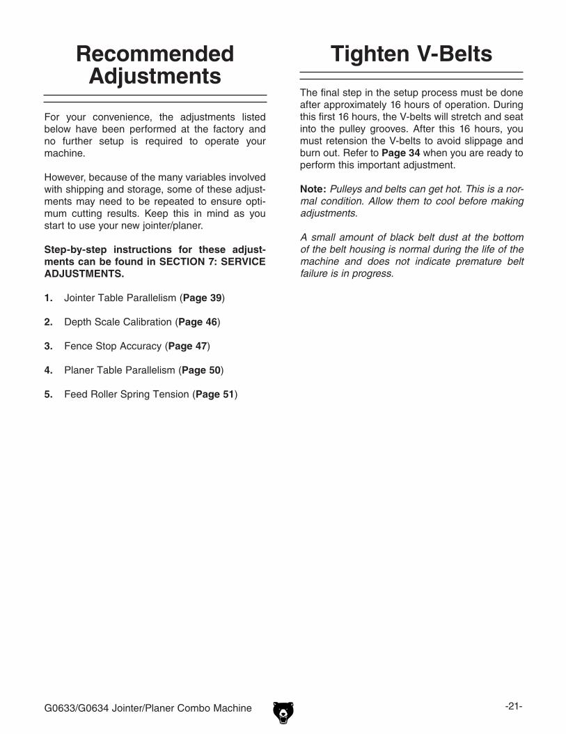
G0633/G0634 Jointer/Planer Combo Machine -21-
Tighten V-Belts
The final step in the setup process must be done after approximately 16 hours of operation. During this first 16 hours, the V-belts will stretch and seat into the pulley grooves. After this 16 hours, you must retension the V-belts to avoid slippage and burn out. Refer to Page 34 when you are ready to perform this important adjustment.
Note: Pulleys and belts can get hot. This is a nor-mal condition. Allow them to cool before making adjustments.
A small amount of black belt dust at the bottom of the belt housing is normal during the life of the machine and does not indicate premature belt failure is in progress.
For your convenience, the adjustments listed below have been performed at the factory and no further setup is required to operate your machine.
However, because of the many variables involved with shipping and storage, some of these adjust-ments may need to be repeated to ensure opti-mum cutting results. Keep this in mind as you start to use your new jointer/planer.
Step-by-step instructions for these adjust-ments can be found in SECTION 7: SERVICE ADJUSTMENTS.
1. Jointer Table Parallelism (Page 39)
2. Depth Scale Calibration (Page 46)
3. Fence Stop Accuracy (Page 47)
4. Planer Table Parallelism (Page 50)
5. Feed Roller Spring Tension (Page 51)
Recommended Adjustments

-22- G0633/G0634 Jointer/Planer Combo Machine
Damage to your eyes, lungs, and ears could result from using this machine without proper protective gear. Always wear safety glasses, a respirator, and hearing protection when operating this machine.
Loose hair and cloth-ing could get caught in machinery and cause seri-ous personal injury. Keep loose clothing and long hair away from moving machinery.
Operation Safety
SECTION 4: OPERATIONS
NOTICEIf you have never used this type of machine or equipment before, WE STRONGLY REC-OMMEND that you read books, trade maga-zines, or get formal training before begin-ning any projects. Regardless of the con-tent in this section, Grizzly Industrial will not be held liable for accidents caused by lack of training.
Basic Jointer Controls
This section covers the basic controls used dur-ing routine jointer operations. To use the machine as a planer, you must perform a changeover (see Jointer-Planer Conversion, Page 24)
START Button: Starts motor only if the EMERGENCY OFF button is in the out position.
OFF Button: Stops motor when pushed in.
EMERGENCY OFF Button: Disables the START button. Enable the START button by twisting the EMERGENCY OFF button until it pops out.
Figure 18. START/STOP button locations.
OFF Button
START Button
EMERGENCY OFF Button

G0633/G0634 Jointer/Planer Combo Machine -23-
Table Movement: Loosen the cap screws on the infeed handgrip and outfeed table adjustment knob before moving the infeed and outfeed tables (Figure 19). Use an adjustable wrench to turn the outfeed adjustment knob.
Figure 19. Table control locations.
Outfeed Table Adj. Knob
Infeed Handgrip
Fence Tilting: The tilt lock (Figure 20) secures the fence at any position in the available range. Fence stops set the fence at 90° or 45° outward. The tilt lock must be tightened before cutting. See Page 47 for more detail on adjusting the fence stops.
Fence Movement: The fence lock keeps the fence in position (Figure 20). To move the fence, loosen the lock and turn the fence adjustment knob to move it as needed.
Figure 20. Fence lock location.
Fence Adj. Knob
Fence Lock
Tilt Lock
Figure 21. Fence flush with table at 45°.
To move the fence to 45° outward, loosen the tilt lock and fence height knobs, move the fence flush against the table (see Figure 21), and tighten the height knobs and tilt lock. Verify the angle with a 45° square. To return the fence to the 90° posi-tion, loosen the tilt lock and height knobs, raise the fence to 90°, and tighten the height knobs and tilt lock. Check the fence angle with a 90° square, and make sure the fence and table are flush.
Fence Height Knobs
Cap Screw Cap Screw

-24- G0633/G0634 Jointer/Planer Combo Machine
Jointer-Planer Conversion
The Model G0633/G0634 is ready for jointer operations after it is setup. To use the machine as a planer, you must perform a conversion.
To set up the machine for planer operations:
1. DISCONNECT THE JOINTER/PLANER FROM THE POWER SOURCE!
2. Remove the cutterhead guard.
3. Loosen the quick release knobs (Figure 23) and slide the fence off the machine.
Figure 23. Fence removal.
4. Remove the dust hose from the jointer dust port.
Quick Release Knobs
Basic Planer Controls
This section covers the basic controls used during routine planer operations.
See Page 22 for a description of START/STOP/EMERGENCY OFF buttons.
Table Height Handwheel: To move the planer table, rotate the table height handwheel (Figure 22).
Table Lock Lever: Turn the lever clockwise to prevent the table moving during planer opera-tions; loosen to move the table handwheel. Table Height Scale: Read depth-of-cut from the inch/millimeter scale.
Change Lever: When the lever is in the "up" posi-tion this converts the machine to planer opera-tions.
Figure 22. Planer table control locations.
Change Lever Table Height
HandwheelTable Lock
Lever
Table Height Scale

G0633/G0634 Jointer/Planer Combo Machine -25-
5. Turn the table lock lever (Figure 24) clock-wise, pull it out, and turn the table up. The table will lock into place when raised to its highest position as shown in Figure 25.
Figure 24. Infeed table lock lever.
6. Raise the outfeed table in the same manner as you did with the infeed table.
7. Swing the planer dust port clockwise over the cutterhead as shown in Figure 26.
Table Lock Lever
Figure 26. Planer dust port setup.
Planer Dust Port
8. Connect the dust hose to the planer dust port.
9. Flip the change lever (Figure 22) up.
To change the machine for jointer opera-tions:
1. Lower the planer table to below the 4" mark on the table height scale.
2. Reverse Steps 2-9 in the previous subsec-tion. Pull up on the table lock knobs to lower the table. Make sure you lower the planer dust port to the "down" position (as shown in Figure 27).
Figure 27. Planer dust port in "down" position.
Serious personal injury could occur if you place your fingers between the tables and base or between pivot points. Your hands could be pinched or crushed!
Figure 25. Infeed table in "up" position.
Planer Dust Port

-26- G0633/G0634 Jointer/Planer Combo Machine
Here are some rules to follow when choos-ing, jointing, and planing stock on a jointer or thickness planer:
• DO NOT joint or surface plane stock that contains knots. Injury to the operator or damage to the workpiece can occur if the knots become dislodged during the cutting operation.
• DO NOT joint or surface plane against the grain direction. Cutting against the grain increases the likelihood of stock kickback, as well as tear-out on the workpiece.
• Jointing and surface planing with the grain produces a better finish and is safer for the operator. Cutting with the grain is described as feeding the stock so the grain points down and toward you on the jointer (Figure 28) or away from you on the planer (Figure 29), as viewed from the edge.
Note: If the grain changes direction along the edge of the board, decrease the cutting depth and make additional passes.
Figure 28. Correct and incorrect grain alignment to cutterhead (jointer).
With Grain
Against Grain
CORRECT
INCORRECT
Stock Inspection and Requirements
With Grain
Against Grain
CORRECT
INCORRECT
Figure 29. Correct and incorrect grain alignment to cutterhead (planer).
• Remove foreign objects from the stock. Make sure that any stock you process with the jointer/planer is clean and free of any dirt, nails, staples, tiny rocks or any other foreign objects, which if they hit the knives or inserts and are drawn into the dust collector, may cause a fire hazard. The particles may also damage the knives/inserts. Wood stacked on a concrete floor can have small pieces of stone or concrete pressed into the surface.
• Only process natural wood fiber through your jointer/planer. Never joint MDF, par-ticle board, plywood, laminates or other syn-thetically made materials.
• Make sure all stock is sufficiently dried before jointing or planing. Wood with a moisture content over 20% will cause unnec-essary wear on the knives/inserts and poor cutting results. Excess moisture can also hasten rust and corrosion.
• Scrape all glue off of boards before plan-ing.
• Keep your work area clear.
Jointer Specific Rules:
• Make sure your workpiece exceeds the minimum dimension requirements (Figures 30 & 31) before edge jointing or surface planing, or it may break or kick back during the operation!

G0633/G0634 Jointer/Planer Combo Machine -27-
15 30
45
PreviouslyJointedEdge
Squaring stock involves four steps performed in the order below:
1. Surface Plane on the Jointer—The con-cave face of the workpiece is surface planed flat with a jointer.
Previously Jointed Edge
Previously Surface
Planed Face
2. Surface Plane on the Thickness Planer—The opposite face of the workpiece is surface planed flat with a thickness planer.
3. Edge Joint on the Jointer—The concave edge of the workpiece is jointed flat with a jointer.
4. Rip Cut on a Table Saw—The jointed edge of the workpiece is placed against a table saw fence and the opposite edge cut off.
Squaring Stock
Figure 30. Minimum dimensions for edge jointing and surface planing (jointer).
1⁄2" Min.
1" Min.
12" Min. 12" Min.
1⁄2" Min.
1" Min.
Thickness Planer Specific Rules:
• Use the full width of the planer. Alternate between the left, the right, and the middle when feeding narrower lumber into the plan-er. Your knives/inserts will remain sharp much longer.
Figure 31. Minimum dimensions for surface planing (thickness planer).
1⁄4" Min.
1" Min.
12" Min.

-28- G0633/G0634 Jointer/Planer Combo Machine
The purpose of surface planing on the jointer is to make one flat face on a piece of stock (see Figures 32 & 33) to prepare it for surface planing on the thickness planer.
To surface plane on the jointer:
1. Read and understand SECTION 1: SAFETY, beginning on Page 8.
2. Make sure your stock has been inspected for dangerous conditions as described in the Stock Inspection & Requirements instruc-tions, beginning on Page 26.
3. Set the cutting depth for your operation. (We suggest 1⁄32" for surface planing, using a more shallow depth for hard wood species or for wide stock.)
4. Make sure your fence is set to 90˚.
5. If your workpiece is cupped (warped), place it so the concave side is face down on the surface of the infeed table.
6. Start the jointer.
7. With a push block in each hand, press the workpiece against the table and fence with firm pressure, and feed the workpiece over the cutterhead.
Note: If your leading hand (with push block) gets within 4" of the cutterhead, lift it up and over the cutterhead, and place the push block on the portion of the workpiece that is on the outfeed table. Now, focus your pres-sure on the outfeed end of the workpiece while feeding, and repeat the same action with your trailing hand when it gets within 4" of the cutterhead. To keep your hands safe, DO NOT let them get closer than 4" from the cutterhead when it is moving!
8. Repeat Step 7 until the entire surface is flat.
NOTICEIf you are not experienced with a jointer, set the depth of cut to 0", and practice feeding the workpiece across the tables as described. This procedure will better pre-pare you for the actual operation.
RemovedSurface
Figure 33. Illustration of surface planing results.
Failure to use push blocks when surface planing may result in cutterhead contact, which will cause serious personal injury. Always use push blocks to protect your hands when surface planing on the jointer.
Figure 32. Typical surface planing operation.
Surface Planing

G0633/G0634 Jointer/Planer Combo Machine -29-
The purpose of edge jointing is to produce a fin-ished, flat-edged surface (see Figures 34 & 35) that is suitable for joinery or finishing. It is also a necessary step when squaring rough or warped stock.
RemovedSurface
Figure 35. Illustration of edge jointing results.
To edge joint on the jointer:
1. Read and understand SECTION 1: SAFETY, beginning on Page 8.
2. Make sure your stock has been inspected for dangerous conditions as described in the Stock Inspection & Requirements instruc-tions, beginning on Page 26.
3. Set the cutting depth for your operation. (We suggest between 1⁄16" and 1⁄8" for edge jointing, using a more shallow depth for hard wood species or for wide stock.)
4. Make sure the fence is set to 90˚.
5. If your workpiece is cupped (warped), place it so the concave side is face down on the surface of the infeed table.
6. Start the jointer.
7. Press the workpiece against the table and fence with firm pressure. Use your trailing hand to guide the workpiece through the cut, and feed the workpiece over the cutterhead.
Note: If your leading hand gets within 4" of the cutterhead, lift it up and over the cutterhead, and place it on the portion of the workpiece that is over the outfeed table. Now, focus your pressure on the outfeed end of the workpiece while feeding, and repeat the same action with your trailing hand when it gets within 4" of the cutterhead. To keep your hands safe, DO NOT let them get closer than 4" from the cutterhead when it is mov-ing!
8. Repeat Step 7 until the entire edge is flat.
NOTICEIf you are not experienced with a jointer, set the depth of cut to 0", and practice feeding the workpiece across the tables as described below. This procedure will better prepare you for the actual operation.
Figure 34. Typical edge jointing operation.
Edge Jointing

-30- G0633/G0634 Jointer/Planer Combo Machine
The purpose of bevel cutting is to cut a specific angle into the edge of a workpiece (see Figures 36 & 37).
The Model G0633/G0634 has preset fence stops at 45˚ outward and 90˚. If your situation requires a different angle, the preset fence stops can be easily adjusted for your needs.
To bevel cut on the jointer:
1. Read and understand SECTION 1: SAFETY, beginning on Page 8.
2. Make sure your stock has been inspected for dangerous conditions as described in the Stock Inspection & Requirements instruc-tions, beginning on Page 26.
3. Set the cutting depth for your operation. (We suggest between 1⁄16" and 1⁄8" for bevel cut-ting, using a more shallow depth for hard wood species or for wide stock.)
4. Make sure your fence is set to the angle of your desired cut.
5. If your workpiece is cupped (warped), place it so the concave side is face down on the surface of the infeed table.
6. Start the jointer.
7. With a push block in your leading hand, press the workpiece against the table and fence with firm pressure, and feed the workpiece over the cutterhead.
Note: If your leading hand gets within 4" of the cutterhead, lift it up and over the cutterhead, and place the push block on the portion of the workpiece that is on the outfeed table. Now, focus your pressure on the outfeed end of the workpiece while feed-ing, and repeat the same action with your trailing hand when it gets within 4" of the cutterhead. To keep your hands safe, DO NOT let them get closer than 4" from the cutterhead when it is moving!
8. Repeat Step 7 until the angled cut is satis-factory to your needs.
RemovedSurface
Figure 37. Illustration of bevel cutting results.
NOTICEIf you are not experienced with a jointer, set the depth of cut to 0", and practice feeding the workpiece across the tables as described below. This procedure will better prepare you for the actual operation.
Figure 36. Typical bevel cutting operation.
Bevel Cutting

G0633/G0634 Jointer/Planer Combo Machine -31-
The G0633/G0634 table moves approximately 1⁄16" with one turn of the handwheel.
The basic steps of operating the planer are as follows:
1. Put on safety glasses.
2. Unless your workpiece is very flat, surface plane the workpiece on the jointer until it is flat—having the face flat will ensure that it sits flat on the planer table during operation.
3. Adjust the table height to slightly lower than your workpiece height to ensure the first cut is as light as possible (approximately 1⁄32"–1⁄16") .
4. Start the planer.
5. Place the flat side of the board down on the table (on the left side, facing the front of the machine), and feed the workpiece through the planer—in the opposite direction as when jointing. Make sure not to stand directly in front or behind the workpiece to avoid kick-back injury.
Basic Planer Operation
—If the cut is too heavy and bogs down the planer, turn the planer OFF immediately, allow it to come to a complete stop, remove the workpiece, and repeat Steps 3–5.
6. Measure your workpiece thickness and adjust the table height as necessary to take a lighter or heavier pass, depending on your needs. For most wood types, 1⁄16" per pass is a good cutting depth.
Note: Any time you switch directions with the table height handwheel, there will be a small amount of backlash—so the first crank of the handwheel after switching directions will be slightly less than 1⁄16". However, as long as you move the handwheel in the same direc-tion during operation, backlash will not be a factor.

-32- G0633/G0634 Jointer/Planer Combo Machine
SECTION 5: ACCESSORIES
G1738—Rotacator™ Precision Planer ToolThe Rotacator is a dial indicator on a magnetic base and is designed for quickly and accurately setting the critical tolerances needed when adjust-ing any planer, so that nasty surprises such as non-parallel and chattered cuts can be eliminated. A great setup tool for other machines! Accurate to 0.001". Indicator rotates 360˚.
Figure 38. Rotacator™ Precision Planer Tool.
H9816—Power Twist® V-Belt - 3/8" x 60"Smooth running with less vibration and noise than solid belts. The Power Twist® V-belts can be customized in minutes to any size—just add or remove sections to fit your needs. Requires two Power Twist® V-belts to replace the stock V-belts on your Model G0633/G0634.
Figure 40. H9816 Power Twist® V-Belt.
Figure 39. Recommended products for protect-ing unpainted cast iron/steel parts on machinery.
G5562—SLIPIT® 1 Qt. GelG5563—SLIPIT® 12 oz SprayG2871—Boeshield® T-9 12 oz SprayG2870—Boeshield® T-9 4 oz SprayH3788—G96® Gun Treatment 12 oz SprayH3789—G96® Gun Treatment 4.5 oz Spray
Figure 41. Straightedges.
G9643—8" Precision StraightedgeG9644—12" Precision StraightedgeH2675—16" Precision StraightedgeIdeal for aligning your outfeed bed to the cutterhead and calibrating your depth scale. These grade 00 heavy-duty stainless steel straightedges are manufactured to DIN874 standards for profes-sional results in set-up and inspection work.

G0633/G0634 Jointer/Planer Combo Machine -33-
T24736—Carbide Inserts (10 Pack)These indexable carbide inserts can be rotated to provide four factory sharp edges before replace-ment.
Figure 44. T24736 Carbide Inserts.
H9885—HSS Knives for G0633 (Set of 3)
G9256—6" Dial CaliperG9257—8" Dial CaliperG9258—12" Dial CaliperEssential for planing, jointing, or sanding to criti-cal tolerances. These traditional dial calipers are accurate to 0.001" and can measure outside surfaces, inside surfaces, and heights/depths. Features stainless steel, shock resistant construc-tion and a dust proof display. An absolute treat for the perfectionist!
Figure 45. Grizzly® Dial Calipers.
H4978—Deluxe Earmuffs - 27dBH4979—Twin Cup Hearing Protector - 29dBT20446—Classic Earplugs, 200-pair - 31dBProtect yourself comfortably with a pair of cush-ioned earmuffs. Especially important if you or employees operate for hours at a time.
Figure 43. Hearing protection.
H4978
T20446
H4979
Figure 42. Our most popular safety glasses.
Basic Eye ProtectionT20501—Face Shield Crown Protector 4"T20502—Face Shield Crown Protector 7"T20503—Face Shield WindowT20451—“Kirova” Clear Safety GlassesT20452—“Kirova” Anti-Reflective S. GlassesT20456—DAKURA Safety Glasses, Black/Clear
T20451
T20452
T20502
T20503
T20456

-34- G0633/G0634 Jointer/Planer Combo Machine
Always disconnect power to the machine before performing maintenance. Failure to do this may result in serious person-al injury.
SECTION 6: MAINTENANCE
For optimum performance from your machine, follow this maintenance schedule and refer to any specific instructions given in this section.
Daily Check:• Clean unpainted cast iron parts of jointer and
planer tables• Lubricate feed rollers
Weekly Check:• Clean cutterhead
Monthly Check:• Inspect V-belt tension, damage, or wear• Clean/vacuum dust buildup from inside cabi-
net and off motor• Lubricate worm gear• Lubricate roller chains• Lubricate elevation lead screw• Lubricate worm shaft
Schedule
Vacuum excess wood chips and sawdust, and wipe off the remaining dust with a dry cloth—this ensures moisture from wood dust does not remain on bare metal surfaces. Treat all unpainted cast iron and steel with a non-staining lubricant after cleaning. We recommend products like SLIPIT®, G96® Gun Treatment, or Boeshield® T-9 (see Page 32 for more details).
Cleaning
V-Belts
V-belt removal and replacement involves remov-ing the V-belts, rolling them off of the pulleys, replacing them with new belts, then retensioning them.
Always replace V-belts as a set, or belt tension may not be even among the belts and may cause premature belt failure.
Consider replacing stock belts with Power Twist V-belts (see Page 32) to reduce vibration and noise, and increase belt lifespan.
To adjust/replace belts the V-belts:
1. DISCONNECT THE JOINTER/PLANER FROM THE POWER SOURCE!
2. Remove the five hex bolts securing the V-belt cover (see Figure 46).
3. Remove the fence and fence bracket, then remove the motor access cover and belt ten-sion knob (Figure 46).
Figure 46. Removing bolts on V-belt cover and belt tension knob (inset).

G0633/G0634 Jointer/Planer Combo Machine -35-
4. Using a 14mm wrench, loosen the four adjustment nuts and raise the motor (see Figure 47) to remove V-belt tension. It may help to use a 2x4 to lift the motor.
8. Replace the motor access cover, fence brack-et, and fence.
5. Remove both the belts and replace them with a new set.
6. Lower the motor and reinstall the belt tension knob.
7. Using the belt tension knob, adjust the V-belt tension so there is approximately 1⁄4"–1⁄2" deflection when the V-belts are pushed with moderate pressure as shown in Figure 48.
Note: After the first 16 hours of belt life, retension the belts, as they will stretch and seat during this time.
Figure 47. Removing V-belt tension.
PulleyDeflection
Pulley
Figure 48. Checking V-belt tension.
Adjustment Nuts
Since all bearings are sealed and permanently lubricated, simply leave them alone until they need to be replaced. DO NOT lubricate them.
Proper lubrication of other jointer/planer compo-nents is essential for long life and trouble-free operation. Below is a list of components that require periodic lubrication. Schedules are based on daily use. Adjust accordingly for your level of use.
Lubrication
Roller Chains: Inspect monthly and lubricate with multi-purpose grease when needed to avoid rust and binding. See the locations shown in Figure 49, and refer to Parts Breakdown, Part P0633310 and P0633311 on Page 60. Remove the fence assembly and V-belt cover to gain access.
Figure 49. Roller chains.
Always disconnect power to the machine before lubricating! Failure to do this may result in serious personal injury.
1⁄4" –1⁄2"

-36- G0633/G0634 Jointer/Planer Combo Machine
Lead Screw: The lead screw should be lubri-cated with multi-purpose grease once a month. See Figure 50 and Parts Beakdown, P0633411, Page 61 for location. Remove the left side access panel for ingress.
Figure 51. Fence lubrication locations.
Planer Column: Clean with solvent, wipe dry, and relubricate with multi-purpose grease when needed.
Worm Gear: Inspect every six months and lubri-cate with multi-purpose grease when needed (see Parts Breakdown, P0633409). Remove the worm gear box (see P0633407, Page 61) to inspect.
Figure 50. Planer column and lead screw.
Planer Column
Lead Screw
Fence: Lubricate with multi-purpose grease when needed in the locations shown in Figure 51.

G0633/G0634 Jointer/Planer Combo Machine -37-
Review the troubleshooting and procedures in this section to fix or adjust your machine if a problem devel-ops. If you need replacement parts or you are unsure of your repair skills, then feel free to call our Technical Support at (570) 546-9663.
SECTION 7: SERVICE
Troubleshooting
Motor & Electrical
Symptom Possible Cause Possible SolutionMotor will not start or fuses or circuit breakers blow.
1. Emergency off button depressed. 2. Short circuit in line cord or plug.
3. Start capacitor is at fault.4. Thermal protection circuit breaker amper-
age is set too low or motor is at fault.
5. Open circuit in motor or loose connections.
1. Rotate clockwise until it pops out/replace.2. Repair or replace cord or plug for damaged insula-
tion and shorted wires.3. Replace start capacitor.4. Unplug machine, open magnetic switch cover, turn
amperage dial on Thermal Protection Circuit Breaker to a higher amperage setting. If switch is maxed out, replace motor.
5. Inspect all lead connections on motor for loose or open connections.
Motor fails to devel-op full power or motor decreases rapidly with load, overheats, or stalls.
1. Motor run capacitor at fault.2. Motor overloaded during operation.3. Air circulation through the motor restricted.4. Motor overloaded during operation.5. Thermal protection circuit breaker amper-
age is set too low or motor is at fault.
6. Short circuit in motor or loose connections.
7. Circuit breaker tripped.
1. Replace run capacitor.2. Reduce cutting load; take lighter cuts.3. Clean out motor to provide normal air circulation.4. Reduce cutting load; take lighter cuts.5. Unplug machine, open magnetic switch cover, turn
amperage dial on Thermal Protection Circuit Breaker to a higher amperage setting. If switch is maxed out, replace motor.
6. Repair or replace connections on motor for loose or shorted terminals or worn insulation.
7. Install correct circuit breaker; reduce number of machines running on that circuit.
Cutterhead slows or squeals when cut-ting, especially on start-up.
1. V-belt loose.2. V-belt worn out.
1. Tighten V-belt (Page 34).2. Replace V-belt (Page 34).
Loud repetitious noise coming from machine.
1. Pulley set screws or keys are missing or loose.
2. V-belts are damaged.3. Motor fan is hitting the cover.
1. Inspect keys and set screws. Replace or tighten if necessary.
2. Replace V-belts (Page 34).3. Adjust fan cover mounting position, tighten fan, or
shim fan cover.
Table (Jointer)Symptom Possible Cause Possible Solution
Tables are hard to adjust.
1. Table gibs are too tight. 1. Adjust table gibs (Page 49).
Tables do not lock. 1. Table lock levers too high or too low. 1. Adjust lock nuts and bolts.

-38- G0633/G0634 Jointer/Planer Combo Machine
Symptom Possible Cause Possible SolutionExcessive snipe (gouge in the end of the board that is uneven with the rest of the cut).
1. Outfeed table is set too low.
2. Operator pushing down on trailing end of workpiece.
3. Workpiece is not supported as it leaves the planer.
1. Align outfeed table with cutterhead knife at top dead center (Page 18).
2. Reduce/eliminate downward pressure on trailing end of workpiece.
3. Support the workpiece as it leaves the outfeed end of the planer.
Workpiece stops/slows in the middle of the cut.
1. Taking too heavy of a cut.2. Table not parallel with head casting.
3. Pitch and glue build up on planer compo-nents.
1. Take a lighter cut.2. Adjust the table so it is parallel to the head casting
(Page 50).3. Clean the internal cutterhead components with a
pitch/resin dissolving solvent.
Chipping (consistent pattern).
1. Knots or conflicting grain direction in wood.
2. Nicked or chipped knife or carbide insert.
3. Taking too deep of a cut.
1. Inspect workpiece for knots and grain direction; only use clean stock.
2. Replace the knife or rotate/replace affected insert (Page 43 or 45).
3. Take a smaller depth of cut. (Always reduce cutting depth when surface planing or working with hard woods.)
Fuzzy grain. 1. Wood may have high moisture content or surface wetness.
2. Dull knives or inserts.
1. Check moisture content and allow to dry if moisture is too high.
2. Rotate/replace the knives or inserts (Page 43 or 45).
Long lines or ridges that run along the length of the board
1. Nicked or chipped knives or inserts(s). 1. Replace or offset knives or rotate/replace inserts (Page 43 or 45).
Uneven knife or insert marks, wavy surface, or chatter marks across the face of the board.
1. Knives not adjusted at even heights in the cutterhead.
2. Carbide inserts not installed evenly.
3. Worn cutterhead bearings.
1. Adjust the knives so they are set up evenly in the cutterhead (Page 43).
2. Make sure carbide inserts do not have debris under them; make sure inserts are torqued down evenly.
3. Replace cutterhead bearings.
Glossy surface. (Planer)
1. Knives or carbide inserts are dull.
2. Cutting depth too shallow.
1. Rotate/replace the knives or inserts (Page 43 or 45).
2. Increase the depth of cut.
Chip Marks (incon-sistent pattern). (Planer)
1. Chips aren't being properly expelled from the cutterhead.
1. Use a dust collection system
Board edge is con-cave or convex after jointing. (Jointer)
1. Board not held with even pressure on infeed and outfeed table during cut.
2. Board started too uneven.
3. Board has excessive bow or twist along its length.
4. Insufficient number of passes.
1. Hold board with even pressure as it moves over the cutterhead.
2. Take partial cuts to remove the extreme high spots before doing a full pass.
3. Surface plane one face so there is a good surface to position against the fence.
4. It may take 3 to 5 passes to achieve a perfect edge, depending on starting condition of board and depth of cut.
Cutting (Jointer and Planer)

G0633/G0634 Jointer/Planer Combo Machine -39-
Checking/Adjusting Jointer Table Parallelism
The outfeed table is preset by the factory parallel with the cutterhead. However, it is critical to check this setting. If the tables are not parallel with the cutterhead or each other, then poor cutting results and kickback can occur.
Tools Needed QtyStraightedge ...................................................... 1Adjustable Wrench ........................................... 1
Checking Outfeed Table Parallelism1. DISCONNECT THE JOINTER/PLANER
FROM THE POWER SOURCE!
2. Put on leather gloves, then remove the cutterhead guard and fence.
3. Place the straightedge on the outfeed table so it hangs over the cutterhead in one of the positions shown in Figure 52.
4. Try to fit a feeler gauge or combination of feeler gauges 0.062" to 0.069" between the bottom of the ruler and the cutterhead body as shown in Figure 53.
—If the feeler gauge slides with slight resis-tance between the ruler and cutterhead and no gaps appear, go to Step 5.
Black Lines RepresentStraightedge PositionsFrom Overhead View
Figure 52. Straightedge positions for verifying if outfeed table is parallel with cutterhead.
—If the feeler gauge(s) do not fit between the ruler and cutterhead, or if there is a gap, adjust the table height until the feeler gauge slides with slight resistance between the ruler and table.
Straightedge
Outfeed Table
0.062"to 0.069"
Feeler Gauge
Figure 53. Using feeler gauge to check outfeed table-cutterhead height.
5. Continue placing the straightedge in the remaining positions shown in Figure 52. In each position, the feeler gauge measurement should be nearly identical.
—If the outfeed table height above the cutterhead is equal across the table in each position, then the outfeed table is already parallel with the cutterhead. Go to Checking Infeed Table Parallelism, on Page 40.
—If the outfeed table height is not equal across the table in any of the positions, then the outfeed table is not parallel with the cutterhead. Correct the outfeed table parallelism, then correct the infeed table parallelism.

-40- G0633/G0634 Jointer/Planer Combo Machine
Checking Infeed Table Parallelism1. Follow all the steps for checking the outfeed
table parallelism to first make sure that the outfeed table is parallel with the cutterhead.
2. Place the straightedge halfway across the infeed table and halfway over the outfeed table, and adjust the infeed table even with the outfeed table, as shown in Figure 55.
Straightedge
Outfeed Table Infeed Table
Figure 55. Infeed and outfeed tables set evenly.
3. Place the straightedge in the positions shown in Figure 56. In each position, the straight-edge should sit flat against both the outfeed table and the infeed table.
Black Lines RepresentStraightedge Positionsfrom Overhead View
Figure 56. Straightedge positions for checking infeed/outfeed table parallelism.
Correcting Outfeed Table to Cutterhead ParallelismThis procedure involves turning the table stop bolts to raise or lower the front of the tables until they are parallel with the cutterhead.
To correct outfeed table parallelism:
1. Loosen the lock nuts on both stop bolts shown in Figure 54 at the front of the table.
—If a knife or insert touches the straightedge, turn the cutterhead so the knives do not interfere.
—If the cutterhead touches the straightedge, raise the outfeed table higher than the cutterhead.
2. Raise the stop bolts just enough so the front edge of the table is higher than the cutterhead, then adjust each stop bolt a sixth of a turn clockwise to gradually lower the table.
3. Check the outfeed table height again (see Steps 3-5, Page 39).
4. Continue lowering the bolts and checking until the outfeed table height above the cutterhead is equal across the table.
Figure 54. Outfeed table stop bolt and lock nut.
Stop Bolts
Lock Nuts
—If the straightedge sits flat against both the infeed and outfeed table, then the tables are parallel. Set the outfeed table height and replace the cutterhead guard (Page 18).
—If the straightedge does not sit flat against both the infeed and outfeed table in any of the positions, then follow the Adjusting Table Parallelism instructions.

G0633/G0634 Jointer/Planer Combo Machine -41-
Adjusting Jointer Table ParallelismFor safe and proper cutting results, the tables must be parallel to the cutterhead. Adjusting them to be parallel is a task of precision and patience, and may take up to one hour to complete. Luckily, this is considered a permanent adjustment and should not need to be repeated for the life of the machine.
Due to the complex nature of this task, we rec-ommend that you double check the current table positions to make sure that they really need to be adjusted before starting.
You can adjust stop bolts on the front of the tables and shim under the back of the tables to adjust them parallel to the cutterhead.
The correct order for adjusting the table parallel-ism is to first adjust the outfeed table parallel with the cutterhead, then adjust the infeed table paral-lel with the outfeed table.
To adjust the jointer table parallelism:
1. Perform the "Checking/Adjusting Table Parallelism" procedure on Page 39, including making any necessary adjustments so the cutterhead and outfeed table are parallel.
2. Place the straightedge halfway across the infeed table and halfway over the outfeed table, and adjust the infeed table even with the outfeed table, as shown in Figure 55.
3. Place the straightedge in one of the positions shown in Figure 56.
5. While an assistant raises the infeed table, slip shims between the hinged shaft and the jointer base, then retighten the cap screw. Shimming the top position will raise the rear cutterhead side of the table, shimming the lower position will raise the rear infeed side.
6. Repeat Step 3 with each of the remaining straightedge positions and adjust the table front to back using the shims as many times as necessary until the infeed table is parallel with the outfeed table.
7. Set the knives (refer to Page 43).
8. Reinstall the cutterhead guard.
—If the front of the infeed table is higher or lower than the outfeed table, adjust the infeed table stop bolts (see Correcting Infeed Table to Cutterhead Parallelism on Page 40).
—If the rear of the infeed table is higher or lower than the outfeed table, shim the infeed table to adjust it parallel with the outfeed table. Follow Steps 4-6.
4. Loosen the cap screws shown in Figure 57.
Figure 57. Infeed table hinged shaft. (Jointer table raised for clarity.)
Cap Screws
Lower Shim Location
Hinged Shaft
Uper Shim Location

-42- G0633/G0634 Jointer/Planer Combo Machine
Inspecting Knives (G0633 Only)
Tools Needed: QtyKnife Setting Gauge .......................................... 1Straightedge ...................................................... 1
The height of the knives can be inspected with the knife setting jig or with a straightedge.
Inspecting the height of the knives with a straight-edge ensures that they are set evenly with the outfeed table at their highest point in the cutterhead rotation.
To inspect the knives with the knife setting gauge:
1. DISCONNECT THE JOINTER/PLANER FROM THE POWER SOURCE!
2. Remove the cutterhead guard.
3. Raise both tables out of the way.
4. Place the knife setting gauge on the cutterhead, directly over a knife, as shown in Figure 58.
— If both outside legs of the gauge sit firmly on the cutterhead and the middle pad just touches the knife, then that knife is set correctly. (Repeat this inspection with the other knives.)
— If the gauge does not sit firmly on the cutterhead and touch the knife edge as described, then reset that knife. (Repeat this inspection with the other knives before resetting.)
6. Lower the tables back over the cutterhead.
7. REPLACE CUTTERHEAD GUARD!
To inspect the knives with a straightedge:
1. DISCONNECT THE JOINTER/PLANER FROM THE POWER SOURCE!
2. Remove the cutterhead guard or block it out of the way.
3. Using a straightedge on the outfeed table, check the height of each knife at the positions shown in Figure 58.
Figure 59. Checking knife height with a straightedge.
Straightedge
Outfeed Infeed
Black Lines RepresentStraightedge PositionsFrom Overhead View
5. Carefully inspect how the gauge touches the cutterhead and the knife.
Figure 58. Typical gauge positioned over cutterhead knife.
Middle Pad

G0633/G0634 Jointer/Planer Combo Machine -43-
—The knives are set correctly when they just touch the bottom of the straightedge in each of the straightedge positions.
—If the knives do not touch the straightedge or they lift it up in any of the positions, then those knives need to be adjusted.
Adjusting/Replacing Knives (G0633)
Tools Needed: QtyStraightedge ...................................................... 1Hex Wrench 3mm .............................................. 1Wrench 8mm ..................................................... 1
Setting the knives correctly is crucial to the proper operation of the jointer and is very important in keeping the knives sharp. If one knife is higher than the others, it will do the majority of the work, and thus, dull much faster than the others.
There are two options for setting the knives—the straightedge method and the knife setting jig method. Each option has advantages and dis-advantages and the correct one for you will become a matter of personal preference. For best results, the tables must be parallel with each other (Checking/Adjusting Table Parallelism on Page 39) and the outfeed table height must be properly set (Setting Outfeed Table Height on Page 18).
Straightedge Method: A high quality straightedge is held flat against the outfeed table and the knife heights are set to the bottom of the straightedge, as shown in Figure 59. Because the knife projec-tion height from the cutterhead is dependent on the outfeed table height, the outfeed table must be parallel to the cutterhead (Page 39) and set as described in Setting Outfeed Table Height on Page 18 for this method to work correctly.
Figure 61. Cutterhead profile diagram.
Knife
The Model G0633 comes with both jack screws and springs inside the cutterhead to provide two options for adjusting the knives (see Figure 61). Note: Only one of these options is needed to set the knives—see Step 5 for clarification.
Knife Setting Jig Method: Both tables are flipped up to fit the gauge on the cutterhead, as shown in Figure 60, and the knife heights are set to just touch the middle pad of the gauge.
The knife setting gauge makes it easy to ensure that the knives project out of the cutterhead evenly. After using the knife setting gauge to set the knives, you have to re-adjust the outfeed table height to ensure that it is even with the knives at their highest point of rotation.
The included knife gauge is designed to set the knives approximately 0.062" higher than the cutterhead.
Figure 60. Using knife setting gauge to set knife height.

-44- G0633/G0634 Jointer/Planer Combo Machine
5. Loosen the cutterhead gib bolts, starting in the middle and alternating back and forth until all of the gib bolts are loose, but not falling out.
—If this is the first time you are setting the knives, remove the gib and knife from the cutterhead. Decide which adjustment option you are going to use between the jack screws and the springs.
—If you decide to use the jack screws, remove the springs from the cutterhead (they are located directly below the knives).
—If you decide to use the springs, just thread the jack screws completely into the cutterhead so they will not get lost. Replace the gib and knife.
6. Remove and clean the gibs and clean inside the cutterhead slot to remove all pitch or saw-dust. Coat the knives and gibs with a metal protectant (Page 32), then fit the gibs back in the cutterhead with the new knives.
7. Adjusting the knife heights:
Knives are sharp! When adjusting knives, wear gloves or cover knives with rags to avoid contact with knives, which could cause serious personal injury.
To adjust/replace the knives:
1. DISCONNECT THE JOINTER/PLANER FROM THE POWER SOURCE!
2. Remove the cutterhead guard from the table, and flip up the lower the infeed and outfeed tables. This will give you unrestricted access to the cutterhead.
3. Remove the motor access panel to expose the motor pulley.
4. Rotate the motor pulley to give you good access to one of the cutterhead knives.
Jack Screws: Using a 3mm hex wrench, find the jack screws through the access holes in the cutterhead (Figure 62) and rotate them to raise/lower the knife. When the knife is set correctly, it will barely touch the middle pad of the knife setting gauge. For now, only tighten the gib bolts enough to hold the knife in place. Repeat Steps 5–7 with the other knives.
Figure 62. Jack screw access hole.
Springs: Push the knife down with the gauge so that the knife edge is touching the middle pad of the gauge. Hold the gauge down and only tighten the gib bolts enough to hold the knife in place. Repeat Steps 5–7 with the other knives.
8. Rotate the cutterhead to the first knife you started with. Slightly tighten all the gib bolts by following the tightening sequence show in Figure 63. Repeat this step on the rest of the knives, then final tighten each gib bolt.
Figure 63. Gib tightening sequence.
1 23 457 6
9. If you used the knife setting gauge to set the knife heights, use the straightedge to adjust the outfeed table height evenly with the knives at top dead center (the highest point in their rotation). If you used the straightedge to set the knife heights, skip to the next step.
10. Replace the cutterhead guard and the motor access panel.

G0633/G0634 Jointer/Planer Combo Machine -45-
Replacing Carbide Inserts (G0634)
Tools Needed: QtyT-Handle Wrench w/T-20 Torx Bit ..................... 1
The cutterhead is equipped with 56 indexable car-bide inserts. Each insert can be rotated to reveal any one of its four cutting edges. Therefore, if one cutting edge becomes dull or damaged, simply rotate it 90˚ to reveal a fresh cutting edge (Figure 64).
In addition, each insert has a reference dot on one corner. As the insert is rotated, the reference dot location can be used as an indicator of which edges are used and which are new. When the reference dot revolves back around to its starting position, the insert should be replaced.
To rotate or change a carbide insert:
1. DISCONNECT THE JOINTER/PLANER FROM THE POWER SOURCE!
2. Remove any sawdust from the head of the carbide insert Torx screw.
3. Remove the Torx screw and carbide insert.
4. Clean all dust and dirt off the insert and the cutterhead pocket from which the insert was removed, and replace the insert so a fresh, sharp edge is facing outward.
Note: Proper cleaning is critical to achieving a smooth finish. Dirt or dust trapped between the insert and cutterhead will slightly raise the insert, and make noticeable marks on your workpieces the next time you plane.
5. Lubricate the Torx screw threads with a light machine oil, wipe the excess oil off the threads, and torque the Torx screw to 48-50 inch/pounds.
Note: Excess oil may squeeze between the insert and cutterhead, thereby lifting the insert slightly and affecting workpiece finishes.
Figure 64. Insert rotating sequence.
Reference Dot

-46- G0633/G0634 Jointer/Planer Combo Machine
The depth scale on the infeed table can be cali-brated or "zeroed" if it is not correct.
Tools Needed QtyStraightedge ...................................................... 1Phillips Screwdriver ........................................... 1
To calibrate the depth scale:
1. DISCONNECT THE JOINTER/PLANER FROM THE POWER SOURCE!
2. Set the outfeed table height as described in the Setting Outfeed Table Height instruc-tions on Page 18.
3. Use the straightedge to help adjust the infeed table exactly even with the outfeed table, as shown in Figure 65.
Calibrating Depth Scale
Pulley Alignment
Figure 67. Fence and V-belt cover removed.
2. Place a 2" C-clamp on each pulley so the adjustment shaft faces out, place a straight-edge on the clamps, as shown in Figure 68, and visually check pulley alignment.
Figure 68. Checking belt alignment.
4. Using a screwdriver, adjust the scale pointer to zero (Figure 66).
Figure 65. Infeed table even with outfeed table.
Straightedge
InfeedOutfeed
Figure 66. Depth scale adjusted to “0” position.
Tools Needed: QtyStraightedge ...................................................... 1Hex Wrench 3mm .............................................. 1C-Clamps ........................................................... 2
Proper pulley alignment (see Figure 68) prevents premature belt wear. The pulleys are properly aligned when they are parallel and in the same plane as each other.
To align the pulleys:
1. Remove the fence assembly, fence bracket, and the V-belt cover (Figure 67).
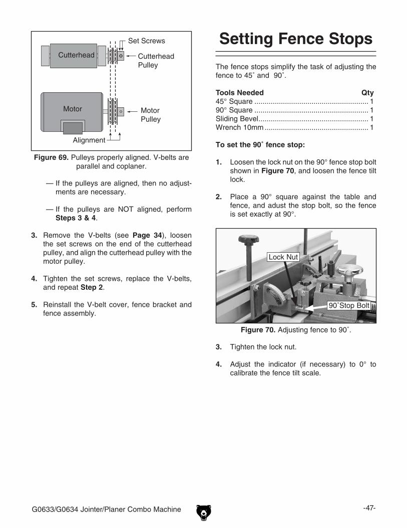
G0633/G0634 Jointer/Planer Combo Machine -47-
— If the pulleys are aligned, then no adjust-ments are necessary.
— If the pulleys are NOT aligned, perform Steps 3 & 4.
3. Remove the V-belts (see Page 34), loosen the set screws on the end of the cutterhead pulley, and align the cutterhead pulley with the motor pulley.
4. Tighten the set screws, replace the V-belts, and repeat Step 2.
5. Reinstall the V-belt cover, fence bracket and fence assembly.
Figure 69. Pulleys properly aligned. V-belts are parallel and coplaner.
Set Screws
CutterheadPulley
MotorPulley
Motor
Alignment
Cutterhead
The fence stops simplify the task of adjusting the fence to 45˚ and 90˚.
Tools Needed Qty45° Square ........................................................ 190° Square ........................................................ 1Sliding Bevel ...................................................... 1Wrench 10mm ................................................... 1
To set the 90˚ fence stop:
1. Loosen the lock nut on the 90° fence stop bolt shown in Figure 70, and loosen the fence tilt lock.
2. Place a 90° square against the table and fence, and adust the stop bolt, so the fence is set exactly at 90°.
Setting Fence Stops
3. Tighten the lock nut.
4. Adjust the indicator (if necessary) to 0° to calibrate the fence tilt scale.
Figure 70. Adjusting fence to 90˚.
Lock Nut
90˚Stop Bolt

-48- G0633/G0634 Jointer/Planer Combo Machine
To set the 45° fence stop:
1. Loosen the fence tilt lock, and position the fence against the 45° stop bolt.
2. Loosen the lock nut on the 45˚ fence stop bolt (Figure 71). The table lock levers can be adjusted if they do
not lock.
Tools Needed QtyWrench 14 mm .................................................. 1
To adjust the table lock levers:
1. DISCONNECT THE JOINTER/PLANER FROM THE POWER SOURCE!
2. Remove the cutterhead guard.
3. Raise the table on the side of the lock lever that does not lock.
4. Loosen the lock nut on the special bolt under the table, as shown in Figure 72.
Adjusting Table Lock Levers
5. Adjust the bolt height a few turns, lower the table, and try engaging the lock lever.
6. Repeat Steps 3-5 until the lever engages, then secure the lock nut.
Figure 72. Table lock lever bolt.
Lock Nut
Special Bolt
Figure 71. Adjusting fence 45˚ outward.
45° Stop Bolt
Lock Nut
3. Adjust the 45˚ stop bolt until the fence is exactly 45° outward while resting on the bolt (check the angle with a sliding bevel set to 135° or with a 45° square.
4. Retighten the lock nut loosened in Step 2.

G0633/G0634 Jointer/Planer Combo Machine -49-
Adjusting Gibs 3. Repeat Steps 1-2 with the outfeed table gib control (Figure 74).
The function of the table gibs is to eliminate excessive play in the table movement. The gibs also control how easy it is to move the tables. Tools Needed QtyAdjustable Wrench ........................................... 1Hex Wrench 8mm .............................................. 1
To adjust the table gibs:
1. Using an adjustable wrench, loosen the infeed table gib nut under the rear of the table (Figure 73).
2. Using an 8mm hex wrench, tighten the gib setscrew a small amount, then check the table by moving it up and down. Adjust the set screw as needed until the friction of the table movement is balanced between mini-mal play and ease of movement, then secure the lock nut.
Note: Tighter gibs reduce play but make it harder to adjust the tables.
Figure 73. Infeed table gib control.
Gib Setscrew
Gib Nut
4. Set the outfeed table height as described in Setting Outfeed Table Height on Page 18.
Figure 74. Outfeed table gib control.
Gib Set ScrewGib Nut

-50- G0633/G0634 Jointer/Planer Combo Machine
Planer Table Parallelism
Maximum Allowable Tolerances:Cutterhead/Table Side-to-Side ..................0.002"Head Casting/Table Front/Back ................0.020"
Tools Needed: QtyRotacator ........................................................... 1Wrench 12mm ................................................... 1Hex Wrench 4mm .............................................. 1Hex Wrench 8mm .............................................. 1
Table parallelism is critical to the operation of the planer. As such, it is essential that the planer table is parallel with the cutterhead (within 0.002") from side-to-side, as illustrated in Figure 75.
Figure 76. Front-to-back parallelism.
Table
Table
Head
Head
Parallel Parallel
Not-Parallel Not-Parallel
FRONT BACK
Figure 75. Side-to-side parallelism of table and cutterhead.
Cutterhead
TableParallel Parallel
SIDE-TO-SIDE
Table
NOT Parallel NOT Parallel
(Front View)
Cutterhead
How the planer table sits in relation to the head casting from front-to-back is also important (see Figure 76). The tolerances on the front-to-back positioning are not as critical as the cutterhead/table side-to-side positioning. Therefore, the max-imum allowable tolerance for the front-to-back parallelism is not more than 0.020".
Table Parallelism InspectionThe easiest way to determine if your planer table has a parallelism problem with the headstock is to plane a workpiece and measure the thickness in multiple locations. If the workpiece is tapered from left-to-right or from front-to-back, then parallelism may be a problem.
Use your Rotacator (Page 32) to further inspect the table parallelism. If you do not have a Rotacator, a wood block and feeler gauges may be used, but extra care must be taken to ensure accuracy. If the table is not within the maximum allowable tolerances, it must be adjusted.
Table Parallelism AdjustmentsThe table is adjusted with the set screws on the cylinder liner.
To adjust the table parallelism:
1. DISCONNECT THE JOINTER/PLANER FROM THE POWER SOURCE!
2. Raise the planer table as far as possible.
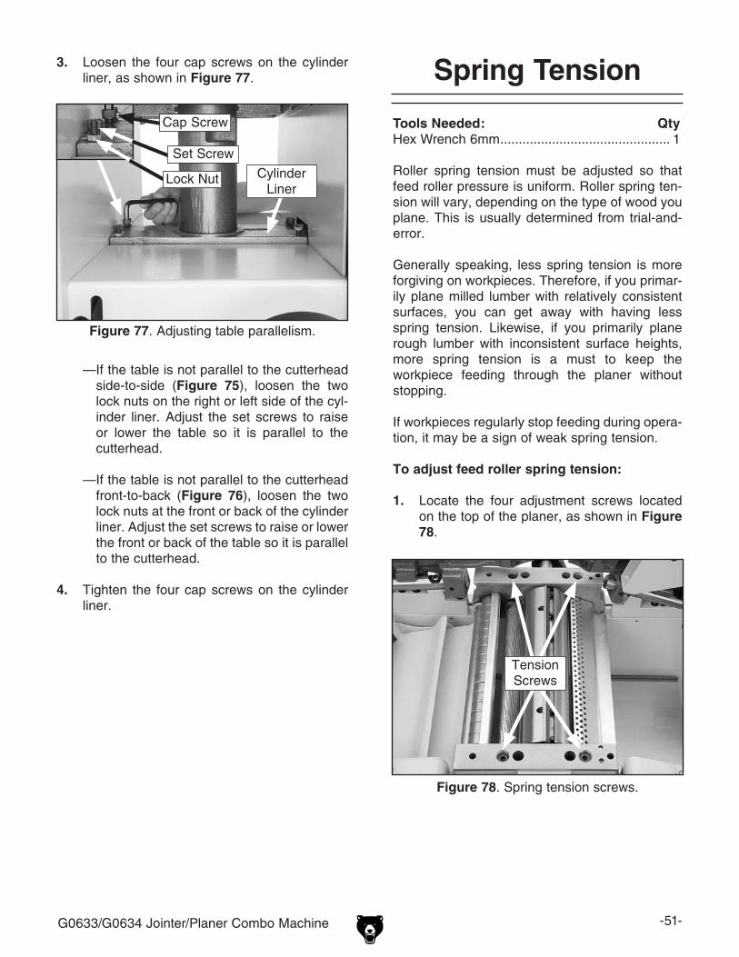
G0633/G0634 Jointer/Planer Combo Machine -51-
— If the table is not parallel to the cutterhead side-to-side (Figure 75), loosen the two lock nuts on the right or left side of the cyl-inder liner. Adjust the set screws to raise or lower the table so it is parallel to the cutterhead.
— If the table is not parallel to the cutterhead front-to-back (Figure 76), loosen the two lock nuts at the front or back of the cylinder liner. Adjust the set screws to raise or lower the front or back of the table so it is parallel to the cutterhead.
4. Tighten the four cap screws on the cylinder liner.
Spring Tension
Tools Needed: QtyHex Wrench 6mm .............................................. 1
Roller spring tension must be adjusted so that feed roller pressure is uniform. Roller spring ten-sion will vary, depending on the type of wood you plane. This is usually determined from trial-and-error.
Generally speaking, less spring tension is more forgiving on workpieces. Therefore, if you primar-ily plane milled lumber with relatively consistent surfaces, you can get away with having less spring tension. Likewise, if you primarily plane rough lumber with inconsistent surface heights, more spring tension is a must to keep the workpiece feeding through the planer without stopping.
If workpieces regularly stop feeding during opera-tion, it may be a sign of weak spring tension.
To adjust feed roller spring tension:
1. Locate the four adjustment screws located on the top of the planer, as shown in Figure 78.
3. Loosen the four cap screws on the cylinder liner, as shown in Figure 77.
Figure 77. Adjusting table parallelism.
CylinderLiner
Figure 78. Spring tension screws.
Tension Screws
Lock Nut
Set Screw
Cap Screw

-52- G0633/G0634 Jointer/Planer Combo Machine
2. Adjust the tension screws counterclockwise so that they are five to seven turns below the top of the head casting.
— If the workpiece slips when you feed it, turn the screws 1⁄2 to 1 turn counterclockwise to increase spring tension.
— If the workpiece is abruptly grabbed when initially fed into the planer, turn the screws 1⁄2 to 1 turn clockwise to decrease spring tension.
Anti-Kickback Fingers
The Model G6333/G0634 provides an anti-kick-back system as a safety feature. The anti-kick-back fingers hang from a rod suspended across the cutterhead casting. The anti-kickback fingers should be inspected regularly.
Check the fingers (Figure 79) to ensure that they swing freely and easily. If the fingers do not swing freely and easily, clean them with a wood resin solvent.
Proper operation of the anti-kickback fin-gers is essential for the safe operation of this machine. Failure to ensure that they are working properly could result in serious operator injury.
Do not apply oil or other lubricants to the anti-kickback fingers. Oil or grease will attract dust, restricting the free movement of the fingers.
Figure 79. Anti-kickback fingers.
Anti-Kickback Fingers

G0633/G0634 Jointer/Planer Combo Machine -53-
Electrical Components
Figure 80. G0633/G0634 magnetic switch.
Figure 82. Junction box and start capacitor.
Figure 83. Run capacitor.
Figure 84. Jointer table limit switch.
Figure 81. Emergency off switch.

-54- G0633/G0634 Jointer/Planer Combo Machine
A
B
AMP
RE
SE
T
96 98
1/2
T1/2 T3/6 NO14
ON
3/4
T2/4
L1/1 L3/5 NO13L2/3
5/6
95
18
2226
RE
SE
T
NC15SDENC16
MAGNETICSWITCH
ASSEMBLY
Ground
Ground
Gro
und
RA-30
Ground220V
MOTOR
RunCapacitor50MFD350VAC
BLACK
WHITE
GREEN
RED
BLUE
COLOR KEYBk
Wt
Gn
Rd
Bl
View this page in color at www.grizzly.com.
The motor wiring shown here is current at the time of printing; however, always use the diagram on the inside of junction box cover when rewiring your motor.
Ground
HotRd
Rd
BkBk
Gn
Gn
Bl
Bl
Bl
BlBkRd
Rd
Rd
Bk
Bk
Rd
Rd
Bk
Bk
Gn
Gn
Gn
Gn
Wt
Wt
WtBk
BkWt
Bk
Bk
Bk
Bk
RdBk
3
4
2
1
LIMITSWITCH
EMERGENCY
STOPNC 12
WtBk
WtBk
GX
Y
Hot L6-30 PLUG(as recommended)
220 VAC
StartCapacitor400MFD125VAC
Wiring Diagram

G0633/G0634 Jointer/Planer Combo Machine -55-
26 5
5-1
5-2
9
7
8
7
8
6
21-1
1-1
21
1-2
10
11
22 23
29
31
17 14
6-1
8 19
24 11
15
18
12-2
12-1
12-3
1212-4
7
16
2
27 28
27
28
13 13-1
13-2
13-3
30
25
14-1
34
6
20
3-1
39
39
1
36 37
38
39
42
41(G0633 Only)
43
12-3
29-2
29-1 29-3 29-5
29-4 29-6
4
5-1 5-2
32
3
40
Stand Assembly

-56- G0633/G0634 Jointer/Planer Combo Machine
REF PART # DESCRIPTION REF PART # DESCRIPTION1 P0633001 FRAME 18 P0633018 POWER CORD1-1 P0633001-1 HINGE SHAFT BRACKET RIGHT 19 P0633019 DEPTH SCALE1-2 P0633001-2 HINGE SHAFT BRACKET LEFT 20 P0633020 LIMIT SWITCH CORD2 P0633002 DRIVE SHAFT COVER 21 PCAP14 CAP SCREW 3/8-16 X 13 P0633003 COVER FRAME 21-1 PCAP26 CAP SCREW 3/8-16 X 1-1/23-1 P0633003-1 COVER 22 PB02 HEX BOLT 1/4-20 X 5/84 P0633004 DOOR 23 PW06 FLAT WASHER 1/45 P0633005 SIDE OPENING COVER 24 P0633024 GROMMET5-1 PB09 HEX BOLT 5/16-18 X 1/2 25 P0633025 GROMMET5-2 PW07 FLAT WASHER 5/16 26 P0633026 STRAIN RELIEF6 PCB22 CARRIAGE BOLT 3/8-16 X 1 27 PW06 FLAT WASHER 1/46-1 P0633006-1 PLATE SCREW 3/8-16 X 2 28 PB51 HEX BOLT 1/4-20 X 3/87 PW02 FLAT WASHER 3/8 29 P0633029 MAGNETIC SWITCH ASSY SDE MP-188 PN08 HEX NUT 3/8-16 29-1 P0633029-1 MAG SWITCH FRONT COVER9 P0633009 MOTOR BRACKET 29-2 P0633029-2 MAG SWITCH BACK COVER10 P0633010 PLANER SCALE 29-3 P0633029-3 CONTACTOR11 PRIV001M STEEL FLUTED RIVET 2 X 5MM 29-4 P0633029-4 OL RELAY SDE RA-30 18-26A12 P0633012 REINFORCEMENT PLATE 29-5 P0633029-5 ON BUTTON12-1 PB32 HEX BOLT 5/16-18 X 5/8 29-6 P0633029-6 OFF BUTTON12-2 PW07 FLAT WASHER 5/16 30 PS22 PHLP HD SCR 10-24 X 5/812-3 PN02 HEX NUT 5/16-18 31 P0633031 STRAIN RELIEF12-4 PB17 HEX BOLT 5/16-18 X 2-3/4 32 PS103 PHLP HD SCR 1/4-20 X 5/1613 P0633013 SQUARE SUPPORT 34 PN05 HEX NUT 1/4-2013-1 PB09 HEX BOLT 5/16-18 X 1/2 36 P0633036 PROTECTION PLATE LEFT13-2 PHTEK35 TAP SCREW 1/4 X 1 37 P0633037 PROTECTION PLATE RIGHT13-3 PW06 FLAT WASHER 1/4 38 G8588 GRIZZLY NAMEPLATE-SMALL14 P0633014 EMERGENCY OFF SWITCH 39 PHTEK12 TAP SCREW #5 X 3/814-1 P0633014-1 SWITCH KNOB 40 PWR1214 WRENCH 12 X 14MM OPEN-END15 P0633015 EMERGENCY STOP SWITCH CORD 41 PWR810 WRENCH 8 X 10MM OPEN-END (G0633)16 P0633016 KNOB BOLT 3/8-16 42 PAW03M HEX WRENCH 3MM17 P0633017 STRAIN RELIEF 43 P0633043 COVER SCREW 5/16-18 X 1-1/2
Stand Parts List

G0633/G0634 Jointer/Planer Combo Machine -57-
Table Assembly
102
105110
101V2
103
112
106107
113
108
108109
109
115
116
122V2
118
114
120121
120121
126
124
117
125
124
117125
133109
130132
131
129
133109
130
132131
134
121
121129
111
113
114
119
128
104-2
215-4215-8 215-5
243
244
243
REF PART # DESCRIPTION REF PART # DESCRIPTION101V2 P0633101V2 INFEED TABLE V2.03.08 120 PW07 FLAT WASHER 5/16102 P0633102 OUTFEED TABLE 121 PCAP07 CAP SCREW 5/16-18 X 3/4103 P0633103 TABLE LIP 122V2 PB03 HEX BOLT 5/16-18 X 1104-2 P0633104-2 JOINTER DUST PORT 124 PCAP19 CAP SCREW 3/8-16 X 1-1/4105 P0633105 HINGE SHAFT A 125 PN02 HEX NUT 5/16-18106 P0633106 HINGE SHAFT B 126 PCAP04 CAP SCREW 1/4-20 X 1/2107 P0633107 OUTFEED TABLE ADJ KNOB 128 PCAP45 CAP SCREW 5/16-18 X 3/8108 P0633108 GUIDE SCREW 129 P0633129 HANDLE109 PN01 HEX NUT 1/2-20 130 P0633130 PLUNGER SCREW 1/2110 P0633110 INFEED HANDGRIP 131 P0633131 PLUNGER111 P0633111 INFEED LOCK LEVER 132 P0633132 COMPRESSION SPRING112 P0633112 OUTFEED LOCK LEVER 133 P0633133 KNOB113 P0633113 PLASTIC KNOB 134 G2405 PUSH BLOCK-SMALL114 PR03M EXT RETAINING RING 12MM 215-4 P0633215-4 L BRACKET115 P0633115 CUTTERHEAD GUARD BRACKET 215-5 P0633215-5 PLATE116 PW06 FLAT WASHER 1/4 215-8 P0633215-8 JDP PLASTIC PLATE117 PB07 HEX BOLT 5/16-18 X 3/4 243 PFS17 FLANGE SCREW 10-24 X 1/2118 P0633118 KNOB SCREW 1/4-20 X 1/2 244 PN07 HEX NUT 10-24119 PS18 PHLP HD SCR 10-24 X 1/4
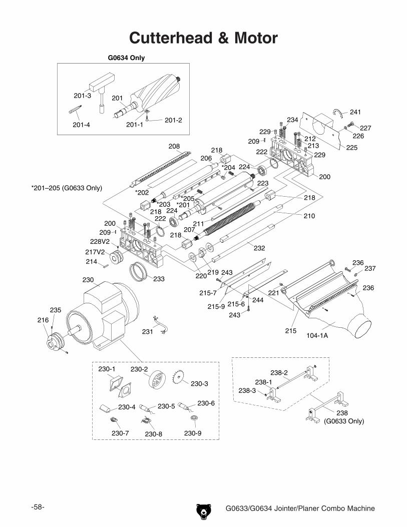
-58- G0633/G0634 Jointer/Planer Combo Machine
218208
206
*203
*202*201–205 (G0633 Only)
*205
211
*204
207
232
210
218
218
224
*201224
222
220219
200
217V2
230
200
225213212
222
216
235
218
234
233
231
229 227226
228V2
209
209
214
229
223
241
230-2230-1
230-3
230-4 230-5
201-1201-2
201-3
201-4
201
G0634 Only
230-6
238-2238-1
238(G0633 Only)
238-3
104-1A
236237
221236
215-6215-9
243
244
243
215
215-7
230-9230-8230-7
Cutterhead & Motor

G0633/G0634 Jointer/Planer Combo Machine -59-
REF PART # DESCRIPTION REF PART # DESCRIPTION104-1A P0633104-1A PLANER DUST PORT V2.09.07 223 PFH58M FLAT HD ALLEN SCR M5-.8 X 12 (G0633)200 P0633200 CUTTERHEAD BLOCK 224 P6205-2RS BALL BEARING 6205-2RS201 P0633201 CUTTERHEAD (G0633) 225 P0633225 GUARD201 P0634201 SPIRAL CUTTERHEAD 12" (G0634) 226 PW06 FLAT WASHER 1/4201-1 H7319 INDEXABLE CUTTER (G0634) 227 PB51 HEX BOLT 1/4-20 X 3/8201-2 PFH35M FLAT HD TORX T20 M6-1 X 15 (G0634) 228V2 P0633228V2 SET SCREW M5-.8 X 4 V2.01.08201-3 P0634201-3 TORX T-HANDLE WRENCH 6MM (G0634) 229 PSS07 SET SCREW 1/4-20 X 1/2201-4 P0634201-4 TORX BIT T-20 (G0634) 230 P0633230 MOTOR 5HP 220V 1PH202 P0633202 KNIFE (G0633) 230-1 P0633230-1 JUNCTION BOX203 P0633203 GIB (G0633) 230-2 P0633230-2 FAN COVER204 P0633204 GIB BOLT (G0633) 230-3 P0633230-3 MOTOR FAN205 P0633205 COMPRESSION SPRING (G0633) 230-4 P0633230-4 CAPACITOR COVER206 P0633206 OUTFEED ROLLER 230-5 P0633230-5 S CAPACITOR 400M 125V 1-3/8 X 3-1/8207 P0633207 INFEED ROLLER 230-6 P0633230-6 R CAPACITOR 50M 350V208 P0633208 COVER 230-7 P0633230-7 CENTRIFUGAL SWITCH 3450209 P0633209 ALIGNMENT PIN 230-8 P0633230-8 CONTACT PLATE210 P0633210 PIVOT PIN 230-9 P0633230-9 MOTOR BEARING211 P0633211 SQUARE SUPPORT 231 P0633231 MOTOR CORD212 P0633212 DOWEL 232 P0633232 PIVOT PIN213 P0633213 COMPRESSION SPRING 233 PVM52 V-BELT FM-52 3L520214 P0633214 CUTTERHEAD PULLEY KEY 234 PCAP55 CAP SCREW 5/16-18 X 3-1/4215 P0633215 DUST CHUTE 235 PSS03 SET SCREW 1/4-20 X 3/8215-6 P0633215-6 BRACKET 236 PS06 PHLP HD SCR 10-24 X 3/8215-7 P0633215-7 PLATE 237 PW03 FLAT WASHER #10215-9 P0633215-9 PDF PLASTIC PLATE 238 P0633238 KNIFE SETTING GAUGE ASSY (G0633)216 P0633216 MOTOR PULLEY 238-1 P0633238-1 KNIFE SETTING GAUGE FEET (G0633)217V2 P0633217V2 PULLEY METRIC V2.01.08 238-2 P0633238-2 KNIFE SETTING GAUGE ROD (G0633)218 P0633218 SUPPORT 238-3 PEC10M E-CLIP 9MM219 P0633219 ANTI KICKBACK FINGER 241 P0633241 CUTTERHEAD ROTATION LABEL220 P0633220 SPACER 243 PFS17 FLANGE SCREW 10-24 X 1/2221 PSS07 SET SCREW 1/4-20 X 1/2 244 PN07 HEX NUT 10-24222 PR26M INT RETAINING RING 52MM
Cutterhead Parts List

-60- G0633/G0634 Jointer/Planer Combo Machine
301
302
313
314319
318
308
306304
312
320309
309
305
303
309
320
322
315321
316
324113
311
310
338329
327326
335
325 337
331332
317
328
334
307 333323
336
330
336
330329
331
330
Drive Assembly
REF PART # DESCRIPTION REF PART # DESCRIPTION113 P0633113 PLASTIC KNOB 320 PR57M INT RETAINING RING 22MM301 P0633301 SPROCKET 66T 321 P0633321 SPRING STUD302 P0633302 SPROCKET 34T 322 PW02 FLAT WASHER 3/8303 P0633303 BUSHING 323 PCAP100 CAP SCREW 3/8-16 X 1/2304 P0633304 SPROCKET 18T 324 P0633324 LEVER305 P0633305 SPACER 325 PSS02 SET SCREW 5/16-18 X 3/8306 P0633306 ARM 326 PSS12 SET SCREW 1/4-20 X 1307 P6204-2RS BALL BEARING 6204-2RS 327 PN05 HEX NUT 1/4-20308 P0633308 TENSION SPRING 328 PCAP70 CAP SCREW 5/16-18 X 2309 P608-2RS BALL BEARING 608-2RS 329 PW07 FLAT WASHER 5/16310 P0633310 ROLLER CHAIN 330 PN02 HEX NUT 5/16-18311 P0633311 ROLLER CHAIN 331 PW01 FLAT WASHER 1/2312 P0633312 CONTACT WHEEL 332 PN01 HEX NUT 1/2-20313 P0633313 LEVER 333 P0633333 BUSHING314 P0633314 TENSION SPRING 334 PCAP05 CAP SCREW 1/4-20 X 3/4315 P0633315 CAM 335 PCAP17 CAP SCREW 1/4-20 X 3/8316 P0633316 CAM SHAFT 336 PCAP07 CAP SCREW 5/16-18 X 3/4317 P0633317 ROLL PIN 337 PLN01 LOCK NUT 3/8-16318 P0633318 SPACER 338 PCAP12 CAP SCREW 5/16-18 X 2-1/2319 P0633319 SPROCKET 19T

G0633/G0634 Jointer/Planer Combo Machine -61-
404
405
411
402
403409
407
401
406
415
408-1419
410417
418
420421422 423
424 425
414421412
413437
438
427
428
429430
434
421433
426
436
431432
414
420
435434
408-2408
Planer Table
REF PART # DESCRIPTION REF PART # DESCRIPTION401 P0633401 PLANER TABLE 420 P0633420 BUSHING402 P0633402 COLUMN 421 PW07 FLAT WASHER 5/16403 P0633403 CYLINDER LINER 422 PLN03 LOCK NUT 5/16-18404 P0633404 LOCK SCREW 423 PLW02 LOCK WASHER 1/4405 P0633405 COLLAR 424 PCAP56 CAP SCREW 1/4-20 x 2-1/4406 P0633406 THICKNESS POINTER 425 PR88M INT RETAINING RING 8MM407 P0633407 GEAR BOX 426 PRP05M ROLL PIN 5 X 30408 P0633408 BUSHING 427 PSS05 SET SCREW 5/16-18 X 1/4408-1 P0633408-1 SELF LUBRICATION SHLDR BUSHING 428 P0633428 FLAT WASHER408-2 P0633408-2 SELF LUBRICATION BUSHING 429 PLW04 LOCK WASHER 3/8409 P0633409 GEAR 430 PB16 HEX BOLT 3/8-16 X 1-1/2410 P0633410 WORM SHAFT 431 PSS01 SET SCREW 5/16-18 X 1411 P0633411 ELEVATION LEAD SCREW 432 PCAP19 CAP SCREW 3/8-16 X 1-1/4412 P0633412 SHIELD PLATE 433 PB09 HEX BOLT 5/16-18 X 1/2413 P0633413 HANDWHEEL 434 PN08 HEX NUT 3/8-16414 PN02 HEX NUT 5/16-18 435 PSS36 SET SCREW 3/8-16 X 2415 P0633415 UNIVERSAL LOCK LEVER 436 PS35 PHLP HD SCR 5/16-18 X 3/4417 P0633417 ROLL PIN 437 P0633437 HANDLE418 P0633418 THRUST BEARING NTB1528 +2AS 438 P0633438 HANDLE SCREW 3/8-16 X 3-3/8419 PR79M INT RETAINING RING 19MM
a
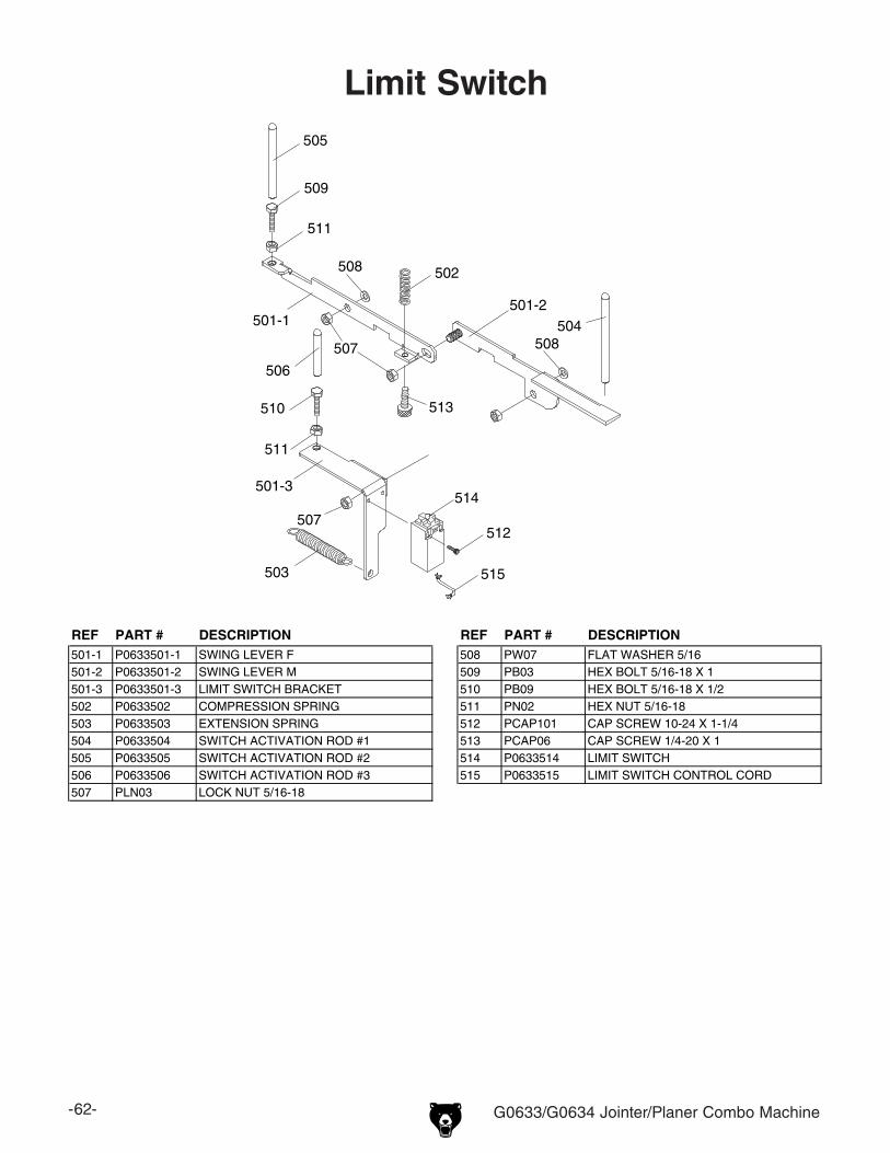
-62- G0633/G0634 Jointer/Planer Combo Machine
501-2504
502
506
501-1
501-3
503
505
509
511
510
511
507512
507
513
514
515
508
508
Limit Switch
REF PART # DESCRIPTION REF PART # DESCRIPTION501-1 P0633501-1 SWING LEVER F 508 PW07 FLAT WASHER 5/16501-2 P0633501-2 SWING LEVER M 509 PB03 HEX BOLT 5/16-18 X 1501-3 P0633501-3 LIMIT SWITCH BRACKET 510 PB09 HEX BOLT 5/16-18 X 1/2502 P0633502 COMPRESSION SPRING 511 PN02 HEX NUT 5/16-18503 P0633503 EXTENSION SPRING 512 PCAP101 CAP SCREW 10-24 X 1-1/4504 P0633504 SWITCH ACTIVATION ROD #1 513 PCAP06 CAP SCREW 1/4-20 X 1505 P0633505 SWITCH ACTIVATION ROD #2 514 P0633514 LIMIT SWITCH506 P0633506 SWITCH ACTIVATION ROD #3 515 P0633515 LIMIT SWITCH CONTROL CORD507 PLN03 LOCK NUT 5/16-18
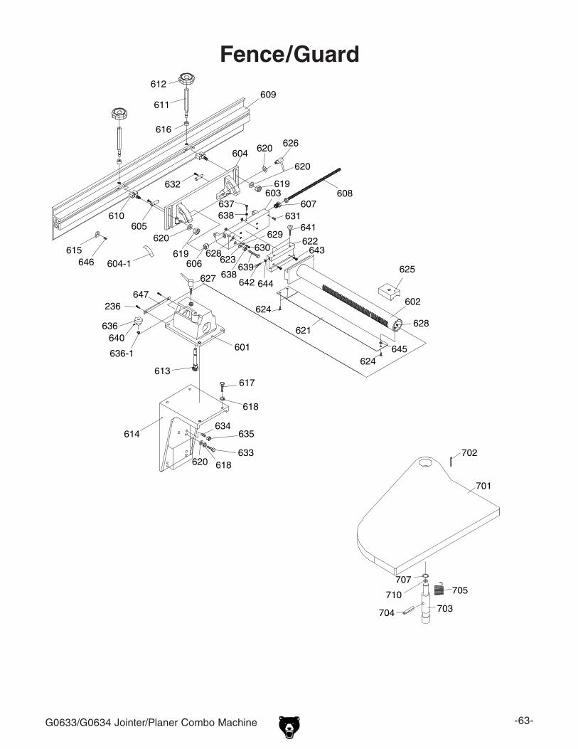
G0633/G0634 Jointer/Planer Combo Machine -63-
612
603
605
606
607
620
619
610
620 626
620
619
618
617
621
602
625
628
629 630
631
632
620 618 633
634 635
637 638
611
616
604
608
614
638 639
615 604-1
624
624 645
641
642
609
643 623
628
622
644
646
601
613
627
636
636-1
640
647 236
Fence/Guard
702
701
707705
703704
710

-64- G0633/G0634 Jointer/Planer Combo Machine
REF PART # DESCRIPTION REF PART # DESCRIPTION601 P0633601 FENCE BASE 628 P0633628 POINTER602 P0633602 ADJUSTMENT TUBE W/RACK 629 PW06 FLAT WASHER 1/4603 P0633603 TRUNNION BRACKET 630 PS07 PHLP HD SCR 1/4-20 X 3/8604 P0633604 TRUNNION 631 PSS03 SET SCREW 1/4-20 X 3/8604-1 P0633604-1 FENCE ANGLE SCALE 632 PS22 PHLP HD SCR 10-24 X 5/8605 P0633605 PIVOT STUD 633 PB12 HEX BOLT 5/16-18 X 1-1/4606 P0633606 SPACER 634 PSS01 SET SCREW 5/16-18 X 1607 P0633607 ADJUSTMENT SCREW 635 PN02 HEX NUT 5/16-18608 P0633608 ADJUSTMENT ROD 636 P0633636 CONTROL KNOB609 P0633609 FENCE 636-1 PR01M EXT RETAINING RING 10MM610 P0633610 SLIDING BOLT 637 PB05 HEX BOLT 1/4-20 X 3/4611 P0633611 ECCENTRIC SHAFT 638 PN05 HEX NUT 1/4-20612 P0633612 LOCK KNOB 3/8-16 639 PB97 HEX BOLT 1/4-20 X 3-1/4613 P0633613 PINION SHAFT 640 PSS11 SET SCREW 1/4-20 X 1/4614 P0633614 FENCE SUPPORT 641 P0633641 KNOB SCREW 1/4615 P0633615 PLASTIC PROTECTION SHOE 642 PB19 HEX BOLT 1/4-20 X 1/2616 P0633616 BUSHING 643 PSB06 CAP SCREW 1/4-20 X 1617 PB03 HEX BOLT 5/16-18 X 1 644 PW06 FLAT WASHER 1/4618 PLW01 LOCK WASHER 5/16 645 PW06 FLAT WASHER 1/4619 PLN03 LOCK NUT 5/16-18 646 PSS29 SET SCREW 10-24 X 1/4620 PW07 FLAT WASHER 5/16 647 P0633647 FENCE BASE PLATE621 P0633621 CUTTER KNIFE GUARD 701 P0633701 CUTTERHEAD GUARD622 P0633622 DOVETAIL BRACKET FOR QUICK RELEASE 702 PRP31M ROLL PIN 6 X 36623 PW06 FLAT WASHER 1/4 703 P0633703 STUD624 PFH19 FLAT HD SCR 1/4-20 X 3/8 704 PRP05M ROLL PIN 5 X 30625 P0633625 TUBE LOCKING SHOE 705 P0633705 TORSION SPRING626 P0633626 UNIVERSAL LOCK LEVER 707 PR48M EXT RETAINING RING 11MM627 P0633627 UNIVERSAL LOCK LEVER 710 P0633710 LOAD WASHER
Fence/Guard Parts List

G0633/G0634 Jointer/Planer Combo Machine -65-
38
800
801 802 803 804
805
806
806
807
808
809
810
Safety labels warn about machine hazards and ways to prevent injury. The owner of this machine MUST maintain the original location and readability of the labels on the machine. If any label is removed or becomes unreadable, REPLACE that label before using the machine again. Contact Grizzly at (800) 523-4777 or www.grizzly.com to order new labels.
Labels
REF PART # DESCRIPTION REF PART # DESCRIPTION38 G8588 GRIZZLY NAMEPLATE-SMALL 805 P0633805 DISCONNECT POWER LABEL800 PLABEL-12 READ MANUAL 2" X 3 5/16" 806 P0633806 CHANGING OPERATIONS WARNING LABEL801 PLABEL-37 RESPIRATOR/GLASSES LABEL 807 PPAINT-1 GRIZZLY GREEN PAINT802 P0633802 MACHINE ID LABEL (G0633) 808 PPAINT-11 GREY PUTTY TOUCH UP PAINT802 P0634802 MACHINE ID LABEL (G0634) 809 PLABEL-14 ELECTRICITY LABEL803 P0633803 CUTTERHEAD GUARD WARNING LABEL 810 P0633810 MODEL NUMBER LABEL (G0633)804 PLABEL-15 EAR PROTECTION 2"X3 5/16"H 810 P0634810 MODEL NUMBER LABEL (G0634)

-66- G0633/G0634 Jointer/Planer Combo Machine
Grizzly Industrial, Inc. warrants every product it sells for a period of 1 year to the original purchaser from the date of purchase. This warranty does not apply to defects due directly or indirectly to misuse, abuse, negligence, accidents, repairs or alterations or lack of maintenance. This is Grizzly’s sole written warranty and any and all warranties that may be implied by law, including any merchantability or fitness, for any par-ticular purpose, are hereby limited to the duration of this written warranty. We do not warrant or represent that the merchandise complies with the provisions of any law or acts unless the manufacturer so warrants. In no event shall Grizzly’s liability under this warranty exceed the purchase price paid for the product and any legal actions brought against Grizzly shall be tried in the State of Washington, County of Whatcom.
We shall in no event be liable for death, injuries to persons or property or for incidental, contingent, special, or consequential damages arising from the use of our products.
To take advantage of this warranty, contact us by mail or phone and give us all the details. We will then issue you a “Return Number,’’ which must be clearly posted on the outside as well as the inside of the carton. We will not accept any item back without this number. Proof of purchase must accompany the merchandise.
The manufacturers reserve the right to change specifications at any time because they constantly strive to achieve better quality equipment. We make every effort to ensure that our products meet high quality and durability standards and we hope you never need to use this warranty.
Please feel free to write or call us if you have any questions about the machine or the manual.
Thank you again for your business and continued support. We hope to serve you again soon.
WARRANTY AND RETURNS

CU
T A
LON
G D
OT
TE
D L
INE
Name _____________________________________________________________________________
Street _____________________________________________________________________________
City _______________________ State _________________________ Zip _____________________
Phone # ____________________ Email _________________________________________________
Model # ____________________ Order # _______________________ Serial # __________________
WARRANTY CARD
The following information is given on a voluntary basis. It will be used for marketing purposes to help us develop better products and services. Of course, all information is strictly confidential.
1. How did you learn about us? ____ Advertisement ____ Friend ____ Catalog ____ Card Deck ____ Website ____ Other:
2. Which of the following magazines do you subscribe to?
3. What is your annual household income? ____ $20,000-$29,000 ____ $30,000-$39,000 ____ $40,000-$49,000 ____ $50,000-$59,000 ____ $60,000-$69,000 ____ $70,000+
4. What is your age group? ____ 20-29 ____ 30-39 ____ 40-49 ____ 50-59 ____ 60-69 ____ 70+
5. How long have you been a woodworker/metalworker? ____ 0-2 Years ____ 2-8 Years ____ 8-20 Years ____20+ Years
6. How many of your machines or tools are Grizzly? ____ 0-2 ____ 3-5 ____ 6-9 ____10+
7. Do you think your machine represents a good value? _____Yes _____No
8. Would you recommend Grizzly Industrial to a friend? _____Yes _____No
9. Would you allow us to use your name as a reference for Grizzly customers in your area? Note: We never use names more than 3 times. _____Yes _____No
10. Comments: _____________________________________________________________________
_________________________________________________________________________________
_________________________________________________________________________________
_________________________________________________________________________________
____ Cabinetmaker & FDM____ Family Handyman____ Hand Loader____ Handy____ Home Shop Machinist____ Journal of Light Cont.____ Live Steam____ Model Airplane News____ Old House Journal____ Popular Mechanics
____ Popular Science____ Popular Woodworking____ Precision Shooter____ Projects in Metal____ RC Modeler____ Rifle____ Shop Notes____ Shotgun News____ Today’s Homeowner____ Wood
____ Wooden Boat____ Woodshop News____ Woodsmith____ Woodwork____ Woodworker West____ Woodworker’s Journal____ Other:

TAPE ALONG EDGES--PLEASE DO NOT STAPLE
FOLD ALONG DOTTED LINE
FOLD ALONG DOTTED LINE
GRIZZLY INDUSTRIAL, INC.P.O. BOX 2069BELLINGHAM, WA 98227-2069
PlaceStampHere
Name_______________________________
Street_______________________________
City______________State______Zip______
Send a Grizzly Catalog to a friend: