model: gmrs200 owner's manual - asa electronics · it sends out radio frequency (rf) signals....
TRANSCRIPT

128-XXXX1 of 24
General Mobile Radio Service (GMRS)
Model: GMRS200
Released: 3- 03 - 2005
Owner's Manual

128-xxxx2 of 28
THIS PAGE LEFT BLANK INTENTIONALLY
2

128-xxxx3 of 28
CAUTIONSAFETY INFORMATIONYour wireless hand-held portable transceiver contains a low powertransmitter. When the PTT button is pushed (or the VOX mode is enabled)it sends out radio frequency (RF) signals. The device is authorized to operateat a duty factor not to exceed 50%. In August 1996, the FederalCommunications Commissions (FCC) adopted RF exposure guidelineswith safety levels for hand-held wireless devices.
Important: To maintain compliance with the FCC’ s RF exposure guidelineshold the transmitter at least 1 inch (2.5 centimeters) from yourface and speak in a normal voice, with the antenna pointed upand away. If you wear the handset on your body while using theheadset accessory, use only the Audiovox supplied carry clipfor this product and ensure that the antenna is at least 1 inch(2.5 centimeters) from your body when transmitting. Use onlythe supplied antenna. Do not use your transceiver with adamaged antenna. Unauthorized antennas, modifications, orattachments could damage the transmitter and may violateFCC regulations.
Performance:Your transceiver will only achieve its maximum operating range whencommunicating with other transceivers across open and flat areas orbetween elevated points. Normally occurring environmental factors suchas buildings, trees, terrain and weather, or interference from other radio orelectrical equipment, may have adverse effects on the transceiver’s effectiverange. These are not indicative of a fault condition.
Avoid placing the GMRS200 radio transceiver for prolonged periods oftime in direct sunlight or temperatures below -4°F(-20°C) or above140°F (60°C).
Place the rubber cover on jacks when not in use.3
128-xxxx4 of 28
WARNINGS:
Battery CareNever attempt to charge alkaline or dry cell batteries, as batteries mayburst causing personal injury and damage to the product. If rechargeablebatteries are used, such as Nickel Metal Hydride (NiMH), use only Audiovox-approved rechargeable batteries. Use of the optional Audiovox chargerwith other brands of batteries is not recommended, as battery chargingtimes will vary with different brands. Refer to the Manufacturer’s instructionsfor charging other brands of batteries.
Battery DisposalIn general, if handled improperly, batteries pose a risk of fire or burns. Donot disassemble, crush, puncture, short external contacts, or dispose ofthe batteries in fire or water. Dispose of the batteries in a environmentallysafe manner and recycle whenever possible.
FCC WARNINGReplacement or substitution of transistors, diodes or other parts of a uniquenature, with parts other than those recommended by the manufacturer,may cause a violation of the technical regulations of Part 15 of FCC Rules.
GMRS LICENSE:USE OF THIS RADIO WITHIN THE UNITED STATES REQUIRES AN FCCGMRS LICENSE. AN INDIVIDUAL 18 YEARS OF AGE OR OLDER, WHO ISNOT A REPRESENTATAIVE OF A FOREIGN GOVERNMENT, IS ELIGIBLETO APPLY FOR A GMRS SYSTEM LICENSE. YOU WILL NEED TWO FORMSFROM THE FCC: FCC FORM 159, AND FCC FORM 605 (MAIN FORM ANDSCHEDULE F). YOU CAN FIND THE FORMS ONLINE AT:HTTP://WWW.FCC.GOV/FORMPAGE.HTML, OR CALL 1-800-418-3676.
4

128-xxxx5 of 28
5
1. Battery Cover2. Keylock/Monitor (M) Button3. Detachable Carry Clip4. Push-To-Talk (PTT) and Func-
tion Confirmation Button5. Antenna6. External Speaker (SP)/
Microphone (MIC)/CHG Jack7. Built-in Speaker
Model GMRS200 (FCC License Required)
8. Liquid Crystal Display (LCD)9. Built-in Microphone
10. Up Channel/Volume Button11. Down Channel/Volume
Button12. MODE/Weather Button13. Power On/Off and SCAN
Button14. Battery Charging Contacts
3
5
4
1
212
11
13
3(REF)
14
7
1(REF)
10
9
6
8PTT-
M-

128-xxxx6 of 28
6
Model GMRS200 DISPLAY
1. Beep Tone Indicator: Icon appears when beep button confirmationtone is selected; icon disappears when tone is off.
2. Key Lock Indicator: Icon appears when the keypad is locked. Thisfunction disables keys such as channel up/down, SCAN and MODE.
3. Monitor Indicator: Icon appears when the Monitor (M) button ispressed and the channel monitor function is activated.
4. Signal Strength Indicator: Icon appears when a signal is beingtransmitted. The icon consists of five bars to indicate transmit signalpower level.
5. HI/LO Indicators: Power level indicator appears when the transmitpower is set to desired output power on the GMRS channels.
6. Large Segment Display: Indicates the channel number in use.7. Scan Indicator: This function allows the user to scan a channel (and
tone code, if present) every .5 second to search for a valid signal.8. RogerBeep Tone On/Off Indicator: This icon appears when the
Roger Beep tone is on, and disappears when tone is not in use.9. Battery Level Indicator: Icon indicates the battery charge level.
10.Signal Receive Indicator: BUSY icon appears when a signal is beingreceived.
11. Weather Mode Indicator: Icon will be on steady when in the weatherband mode. When in the GMRS/FRS mode, the icon will blink whenthe alert is active
1
2
3
4
5
6
7
8
9
1011
12
13
14
LOHI BUSY

128-XXXX7 of 24
7
Equipment and Accessories Supplied1. Radio (4) GMRS2002. Owner’s Manual (1) 128-XXXX
Optional Accessories3. Rechargeable Batteries (4) NiMH, 1.2V, 900mAh,
1. Boom Microphone/Headset GMRSBHST42. Leather Carrying Case GMRS1502LC
Powering the transceiver:Your GMRS200 radio transceiver operates on four rechargeable batteries.Only approved rechargeable batteries can be recharged in the GMRS4WM wall mount charger. This will ensure optimum performancefor the GMRS200. Battery charging time is typically 10-12 hours.Use of other brands of rechargeable batteries is not recommended asbattery charging time will vary. Do not mix old and new, or batteries ofdiffering manufacture, since the charging will be uneven and willresult in decreased battery life.If necessary, four AAA alkaline batteries can be used to power the GMRS200,but note that these type batteries can not be recharged and damage tothe charger or the batteries may result if the units are placed in the GMRS4WM wall mount charger with the alkaline batteries installed.FOR THIS REASON, IT IS NOT RECOMMENDED TO USE ALKALINEBATTERIES IN THE GMRS200.
DO NOT PLACE GMRS200 TRANSCEIVERS IN THE CHARGINGSTAND IF THERE ARE ALKALINE BATTERIES INSTALLED.
12.Small Segment Display: Displays the CTCSS tone option for eachmain channel from 01-38.
13.Dual Watch Mode Indicator: Indicator appears when dual watchmode is active.
14.Voice Activated Transmission (VOX) Indicator: This functionallows hands free conversation. The indicator appears when theVOX mode is activated.

128-XXXX8 of 24
8
Installing the batteries:Battery installation is made more convenient when the carry clip is eitherrotated left or right to the horizontal position, or is removed. Simply rotatethe clip in either direction to the horizontal position. Be careful not to useexcessive force. To remove the clip, press down on the spring release taband pull the clip straight out from the radio body. Next, press down with thethumb at the embossed arrow, slide the battery cover down and lift it awayfrom the compartment. Insert four AAA batteries (alternate positive ends (+)toward the top of the transceiver, starting left-to-right.
2. Then lift cover atbottom to open.Remove cover.
3. Insert four AAA batteries(positive (+) end towardthe top begining at leftside and alternatingpositive terminals asshown).
1. Using thumb,press down onbattery cover atarrow and slidecover down.
CLIP SPRINGRELEASE TAB
BATTERYCOVER
CARRYCLIP
COVERARROW
POSITIVETERMINALS
+ +
+ +

128-xxxx9 of 24
9
The following guidelines will improve performance and provide longeroperating times for the GMRS200:
1. Do not mix old and new batteries.
2. Do not mix alkaline, standard (carbon-zinc) or rechargeablebatteries.
3. If the unit is not to be used for an extended period of time, remove thebatteries. Old or leaking batteries can cause damage to the unit and
will void the warranty.
NOTE: Only Audiovoxapproved rechargeablebatteries (Ni-MH,900mA,1.2V)can be recharged in the radiotransceiver.
MIC/CHG/SPK JACK
GMRS200

128-xxxx10 of 28
Controls:
10
GMRS200 OPERATIONAL MODES
WEATHER BAND
WEATHER AlertSELECT
CHANNELSELECT
ROGERBEEP
BUTTONBEEP
DUALWATCH
VOX LEVELSELECT
CALLSELECT
POWERSELECT
(GMRS Channels Only)
GMRS/FRS BAND
CTCSSSELECT
CHANNELSELECT
NOTE: 1. To switch between GMRS/FRSand Weather Band modes,press and hold the Mode but-ton for 3 seconds. Refer to theappropriate section of thismanual for detailed operatinginstructions for each mode.
Power On-Off/SCAN Button (13)Press and hold the PWR on/off button for at least 2 seconds. You will heara confirming melody to indicate the unit is on. To turn the unit off, press andhold the button for at least 2 seconds.Press this Button momentarily to enable or disable the scan mode.
128-xxxx11 of 28
11
volume. The display will indicate the current volume level between 1 and 7by the small number in the icon ( UL 5 ).
Monitor/Keylock Button (2)This button is used to check activity on the current frequency beforetransmitting. Check activity by pressing the Monitor (M) Button longerthan 2 seconds; the icon will apppear on the display and you willhear static if frequency is clear. Do not transmit if you hear conversation.Hold down the Monitor Button again longer than 2 seconds and the icon will disapppear from the display.The monitor function will temporarily bypass the squelch setting and playall signals on a given channel. This feature is useful when communicatingwith other parties at extreme range.By pressing the monitor button momentarily, the keylock icon ( ) will appear to confirm the functions MODE, SCAN and channel up/down buttons have been disabled.
Push To Talk (PTT) Button (4)Pressing and holding this button will allow you to speak to any transceiverthat is set to the same channel and privacy code setting as yours. Hold thetransceiver approximately 1 to 2 inches from your face as you speak intothe built in microphone (9). After you have finished speaking, release the PTT Button to allow reception of incoming signals. It is not possible totransmit and receive at the same time. The Transmit Signal Level indicator( ) will display the relative strength of the transmitted signal. Whenreceiving an incoming signal, the BUSY icon will appear in the upper rightquadrant of the display. The PTT button can also be used as a two-way callringer. Pressing the button twice quickly will call another party on the samechannel.
Adjusting the Volume (11, 10)With the unit powered on, press the Up Channel/Volume button ( ) toincrease volume and the Down Channel/Volume button ( ) to decrease

128-xxxx12 of 28
12
Down Channel/Volume Button (11)In the standby mode, pressing this button will decrease the listeningvolume. When in function edit mode this button will be used to adjust theunit’s settings.Mode Button (12)This button is used to select the various feature settings in the GMRS/FRSor Weather band modes. Holding the MODE button longer than 2 secondswill toggle between the GMRS/FRS and Weather band modes.
External Microphone (MIC)/Speaker (SPK)/(CHG) Jack (6)This jack accepts an Audiovox Earbud/microphone connector, or theCharging Adapter connector. For equipment and accessories, refer to Page 7 and/or visit the Audiovox web site at www.audiovox.com
Operating Modes and FeaturesGMRS Operation:
- From GMRS/FRS standby mode, press and hold the ( ) button formore than 2 second to turn on power.
- Press the MODE button so the Channel number flashes.- Select the desired channel with the Up (10) and Down (11) Buttons.When receiving a call, the BUSY icon appears to indicate the incom-ing signal.
- Press and hold the PTT button (4) to transmit, then speak into themicrophone clearly and slowly. The Transmit Signal Level indicator( ) will display the relative strength of the transmittedsignal.
Up Channel/Volume Button (10)In the standby mode, pressing this button will increase the listening volume.When in function edit mode this button will be used to adjust the unit’ssettings.

128-xxxx13 of 28
13
- Release PTT Button (4) to receive.- Communication can only be accomplished when the channel and
CTCSS tone frequency of at least two parties are the same.- The CTCSS small segment display will appear next to the main
frequency channel on the display if the CTCSS tone frequencyfunction is enabled.
Channel SelectionIn order to communicate with other GMRS units, both transmitting andreceiving party must be on the same frequency. The GMRS200 has 22channels (frequencies) indicated by the large digits on the LCD displaypanel. Channels 1 through 7 are the shared GMRS/FRS channels.Channels 8-14 are FRS only channels, while channels 15-22 areassigned GMRS only channels. If an FRS only channel (8-14) hasbeen selected, the HI or LO indicator will not be displayed on the LCDpanel; otherwise, for channels 1-7 (GMRS/FRS) and 15-22 (GMRSonly), the HI or LO indicator will be displayed. Communication withAudiovox FRS and compatible units is possible on the shared and FRSonly channels. Before transmitting on the selected channel, press theMonitor (M) Button (2) to check the activity on that channel. If there is activityon the selected channel, change to another channel that is clear.To change the channel:
- From GMRS/FRS standby mode, press the MODE button (12) onceor until the channel number flashes.
- Press the Up Button (10) briefly to move to the next higher mainchannel number.
- Press the Down Button (11) briefly to move to the next lower mainchannel number.
- Press the PTT button momentarily to confirm selection.CTCSS Mode (Sub-Channel) SelectionThe Coded Tone Controlled Squelch System (CTCSS) provides 38 Sub-Fre-quencies. This feature allows you to utilize the coded squelch tones (01–38) within a main channel, and enables you to communicate with another

128-xxxx14 of 28
14
party on the same main channel using the same subcode. (This filters outunwanted transmissions without the same coded squelch tone). Thereare 38 CTCSS Sub-channels for each main channel. A different subcodemay be selected for each of the 22 channels.To change the CTCSS Sub-channel:
- From GMRS/FRS standby mode, press the MODE Button twice; aflashing oF or sub-channel number is displayed. If oF is displayed,press the Up or Down button to enable the CTCSS mode.
- Then press the Up or Down button to select the desired sub-channelfor use (01-38).
- Press the PTT button momentarily to confirm selection.The CTCSS mode can be turned off by selecting the oF icon as the setting.NOTE: To communicate with other GMRS/FRS units, they must be
switched to the same channel and CTCSS subcode. To commu-nicate with other GMRS/FRS units that do not have subcodes,switch your unit to the same channel with the subcode set to oF.The CTCSS subcodes do not prevent others from hearing yourtransmission. This will only allow you to ignore all traffic on agiven channel not using the same subcode.
Transmit Power Selection ModeThis feature permits selection of the transmitting power level to highor low. When operating on FRS only channels (8-15), no power selec-tion is possible or is displayed. Using low power, the unit will have alower transmit range, but battery life will be increased.To access the transmitter power selection function:
- From GMRS/FRS standby mode (shared channels 1-7 or GMRS onlychannel (15-22) selected), press the MODE Button three times untilthe power HI or Lo indication appears with a flashing Po indicationon the display.
- Press the Up or Down button to toggle between the High and Low se-lections.
- Press the PTT button momentarily to confirm selection.

128-xxxx15 of 28
15
VOX and Sensitivity Level SelectionThis selection enables you to set the VOX function and its sensitivity level to compensate for ambient noise in your immediate area. A VOX sensitivity of 3 is the most sensitive, and should be used in a relati-vely quiet surrounding. A VOX sensitivity of 1 is the least sensitive and should be used in a noisy surrounding.To set the VOX sensitivity level:
- Press the MODE button 4 times (3 times for FRS) until the VO iconappears on the display accompanied by the flashing VOX icon and thenumeral 1, 2 or 3 and off.
- Press the Up or Down button to select the 1-3 VOX level sensitivity.- Press the PTT button momentarily to confirm the VOX selection.- The VOX icon will disappear from the display unless VOX mode is
enabled(off).Dual Watch ModeThis feature allows you to monitor two channels at the same time. While indual watch mode, the unit will continuously monitor both the primary anddual watch channel. Received signals will be played for 5 seconds, thenthe unit will resume scanning the two channels. Pressing the PTT buttonduring a received transmission will set the unit to transmit on the samechannel. Pressing the PTT button when no signal is received will set theunit to transmit on the primary channel.To set the Dual Watch Mode:
- From GMRS/FRS standby mode, press the MODE button 5 times (4times for FRS); DW appears flashing on the display. If the dual watchmode is off, the oF icon will also appear flashing.
- To enable the dual watch mode, press the Up or Down button; the dualwatch channel number will flash and start to increase or decrease asthe Up or Down button is pressed.
- To select a subcode for the dual watch channel, press the MODEbutton while the selected dual watch channel is flashing. Then use theUp and Down buttons to select the desired CTCSS subcode.

128-xxxx16 of 28
16
- Press the PTT button momentarily to confirm selection of the dualwatch channel. The display will now alternate between the primarychannel and the dual watch channel just selected.NOTE: Pressing the PTT button during dual watch mode will trans-
mit on the primary channel and suspend dual watch opera-tion for 20 seconds. Dual watch mode will then resume.
- Momentarily press the SCAN button to exit the dual watch mode.
Key ToneThis feature allows the transceiver to sound a confirmation tone wheneverthe following keys are pressed: Monitor (M) Button, Up/Down Buttons, MODEButton or SCAN Button.To turn the key tones on or off:
- From GMRS/FRS standby mode, press the MODE Button 6 times (5times for FRS) until the Bell ( ) icon flashes, and on or oF appears onthe display.
- Press the Up or Down Button to toggle the key tone feature On or Off.- Press the PTT button momentarily to confirm selection.
When the key tone feature is on, the Bell icon appears steady on thedisplay, and the beep tones sound in response to button activation.
Roger Beep ToneThe Roger Beep is a tone which is automatically transmitted whenever thePTT button is released. This tone alerts the receiving party that the trans-mission has been terminated intentionally.To enable and disable the Roger Beep tone:
- From GMRS/FRS standby mode, press the MODE Button 7 times (6times for FRS) until the flashing Roger Beep icon ( ) and on or oFappears on the display.
- Press the Up or Down button to select the tone on or off as desired.
- When enabled, the tone icon ( ) appears steady on the display.- Press the PTT button momentarily to confirm selection.

128-xxxx17 of 28
17
Call Ringer Selection ModeThe transceiver provides 3 user-selectable call ringer melodies to alertyou to an incoming call.To select your favorite call ringer melody:
- From GMRS/FRS standby mode, press the MODE Button 8 times (7times for FRS). CA will appear on the display, together with a flashingnumber between 01 and 03, and an appropriate call ring.
- Press the Up or Down Button to preview and hear the 3 available callmelodies.
- Press the PTT button momentarily to confirm selection.
Channel Scan OperationThis feature allows you to monitor all channels automatically for validsignals. While scanning, you can transmit and receive. When a signal isreceived, the scan is interrupted and will return to scan mode 5 secondsafter reception is terminated.NOTE: While the scan function is active, the MODE button will be
inoperative. The scan mode will reduce the overall battery lifesince the battery save function is overridden.
To enable the channel scan mode:- From GMRS/FRS standby mode, momentarily press the SCAN But
ton; (SCAN) will appear on the LCD display.- The radio will display each channel (1-22) in ascending order as the
scan mode operates to find an active main channel.- If the unit doesn’t find any signals and you want to transmit, press the
PTT button to return to home channel operation. The transceiver willautomatically resume scanning approximately 5 seconds after thecommunication is completed.
- If there is no activity and you want to leave the scan mode, press theSCAN button momentarily and the unit will return to normal operation;the SCAN icon will disappear from the LCD display.

128-xxxx18 of 28
18
Auto Key Lock Selection Mode
This feature prevents accidental channel change to the preferred settingsof the unit. The Auto Key Lock function temporarily disables the MODE, Up/Down and SCAN Buttons.To access the Auto Key Lock selection menu:
- From GMRS/FRS standby mode, press the Monitor Button momentarilyto enable the Auto Key lock function; the unit will beep once and thelock ( ) icon appears on the display.
- The Power, PTT , and Monitor Buttons are not effected.- To unlock the Auto Key function, press the Monitor Button momentarily
the unit beeps once and the lock icon ( ) disappears from thedisplay.
NOTE : If the unit is turned off while Key Lock is on, the Key Lockmode will still be in effect when the unit is again turned on.
Display Backlight Enable OperationBy pressing the MODE or Up/Down button momentarily, the LCD back-light is turned on; the LCD backlight will turn off automatically in about5 seconds.
Weather Band OperationChannel SelectionThis feature provides access to 10 channels within the weather band (7NOAA channels and 3 Canadian marine channels). To select a weatherchannel, the unit must be in the weather channel mode. Press and holdthe MODE button for at least 2 seconds; the weather alert icon ( ) willappear, together with a channel number in the band. Momentarily pressthe MODE button (12) once; the channel number flashes.

128-xxxx19 of 28
To change the channel: - Press the Up Button (10) briefly to move to the next higher
main channel number. - Press the Down Button (11) briefly to move to the next lower main
channel number.NOTE: When the weather band operation mode is entered the transceiverwill bypass the squelch setting and open the channel.
Weather Alert ModeThe weather alert mode notifies the user of unusual weather situationswhen the radio is operating in the GMRS/FRS mode.
To access the weather alert function:
- From Weather Band standby mode, press the MODE button once toaccess the weather channels as instructed above, and use the Upor Down Button to select the desired channel.
- Momentarily press the MODE button again to access the weatheralert function; the weather icon ( ) and AL on or oF appear flashingon the display..
- Use the Up or Down buttons to enable (on)/disable (oF) the alertfunction. The weather icon will stop blinking on the display in theGMRS mode when the alert is disabled.
- Press the PTT Button to confirm your selection.- Press and hold the MODE button for at least 2 seconds to exit the
weather function.
NOTE: When the unit is the GMRS/FRS or Weather Band mode, if aweather alert signal is received, the unit will generate a warn-ing tone.
Battery AlertWhen the battery icon is empty ( ) and flashing on the display, re-charge unit or install fresh batteries.
19
- If the radio is in GMRS/FRS mode, press and hold the MODE buttonfor at least 2 seconds to change to Weather Band mode.

128-xxxx20 of 28
NOTES FOR GOOD COMMUNICATION1 . The GMRS200 22 channels are shared on a ‘take turns’ basis.
This means other groups may be talking on any of the channels.A common code of ethics/courtesy is to switch to another vacantchannel and not to attempt to talk over someone who is already usingthe channel you first selected.
2. The GMRS200 has been designed to maximize performanceand improve transmission range in the field. To avoid interference,it is recommended that you do not use the units closer than 5 feetapart.
3. For best transmission results, always keep your mouth about 2-3inches from the microphone (9) and speak slowly in a normal voice.
4. To increase battery life, avoid features such as Scan and DualWatch. These features will reduce operating time considerably.
Warning• Do not operate the transceiver unless you are licensed to do so.
• Remove the batteries from the transceiver if it is not expected to be usedfor long periods. This will eliminate the possibility of chemicals leakingfrom the batteries and corroding the transceiver.
• Avoid exposing the transceiver to water or extremes of temperature.
• Do not use this device in or near a mining facility, which uses remotelytriggered explosives or in areas labeled “Blasting Area”. Premature oraccidental detonation may result.
• Do not attempt to modify or in any way increase the output of thistransceiver. Its output is designed to meet the legal limits set by the FCC.
• Do not use this device or change its batteries in potentially explosiveatmospheres as sparks in such areas could result in an explosion.
• Turn your transceiver off wherever posted notices restrict the use of radiosor cellular telephones. Facilities such as hospitals may use equipmentthat is sensitive to RF energy.
20

128-xxxx21 of 28
Troubleshooting
21
Weak or no Weak batteries Charge or replace batteriessignal received Channel and privacy Adjust the transceiver’s
code not set the same settings to match thoseas target transceiver settings of the target
transceiverVolume level too low Increase volume levelPTT Button inadvertently Release PTT ButtonpressedExcessive radio interference Change to a differenton a particular channel channelObstruction of radio signal Avoid operating in or near
large buildings or vehiclesUnit beeps, but Batteries extremely Charge or replace batterieswill not function dischargedwhen turned onReception of CTCSS privacy mode Turn on the CTCSS privacyunwanted signals not on mode and set code number to
match the setting of thetarget transceiver.
Interference from Turn the devices off or moveelectronic devices such farther away from them.as computers or TVs
Problem Possible cause Correction
No transmission Weak batteries Charge or replace batterieswhile pressing Incorrect battery polarity Install the batteriesthe PTT Button following the directions in
paragraph Installing theBatteries.
• Turn your transceiver off on board aircraft when requested to do so.
• Do not place your radio in front of a vehicle’s air-bag. If the air-bag de-ploys, it could propel the transceiver like a projectile causing bodily injury.
128-xxxx22 of 28
22
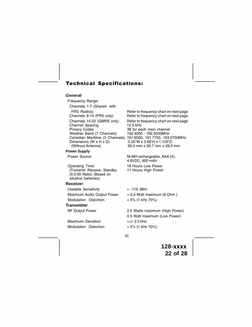
GeneralFrequency Range:Channels 1-7 (Shared withFRS Radios) Refer to frequency chart on next page
Channels 8-14 (FRS only) Refer to frequency chart on next pageChannels 15-22 (GMRS only) Refer to frequency chart on next pageChannel Spacing 12.5 kHzPrivacy Codes 38 for each main channelWeather Band (7 Channels) 162.4000 - 162.5500MHzCanadian Maritime (3 Channels) 161.6500, 161.7750, 163.2750MHzDimensions (W x H x D) 2.25"W x 3.68"H x 1.125"D(Without Antenna) 56.0 mm x 93.7 mm x 28.5 mm
Power SupplyPower Source Ni-MH rechargeable, AAA (4),
4.8VDC, 900 mAhOperating Time: 18 Hours Low Power(Transmit: Receive: Standby 11 Hours High Power(5:5:90 Ratio) (Based onalkaline batteries)
ReceiverUseable Sensitivity > -119 dBmMaximum Audio Output Power > 0.3 Watt maximum (8 Ohm )Modulation Distortion < 5% (1 kHz 70%)
TransmitterRF Output Power 2.0 Watts maximum (High Power)
0.5 Watt maximum (Low Power)Maximum Deviation <+/- 2.5 kHzModulation Distortion < 5% (1 kHz 70%)
��������� �������� �����
128-xxxx23 of 28
23
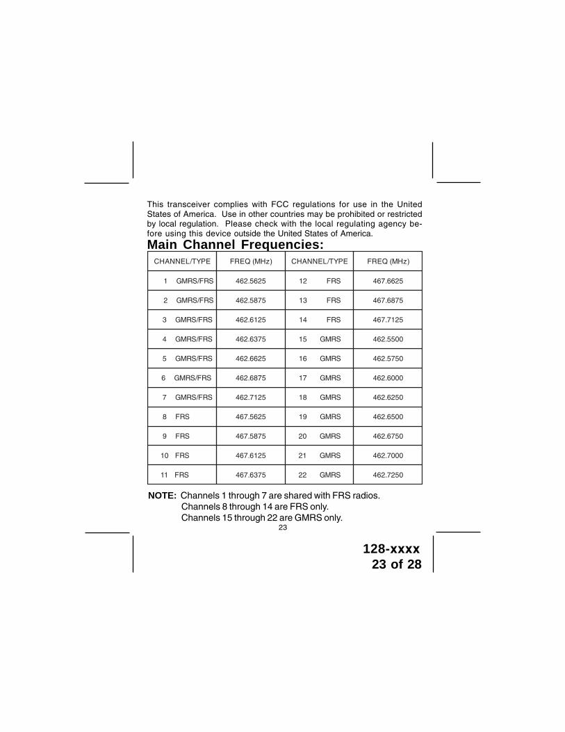
This transceiver complies with FCC regulations for use in the UnitedStates of America. Use in other countries may be prohibited or restrictedby local regulation. Please check with the local regulating agency be-fore using this device outside the United States of America.
NOTE: Channels 1 through 7 are shared with FRS radios.Channels 8 through 14 are FRS only.Channels 15 through 22 are GMRS only.
Main Channel Frequencies:EPYT/LENNAHC )zHM(QERF EPYT/LENNAHC )zHM(QERF
SRF/SRMG1 5265.264 SRF21 5266.764
SRF/SRMG2 5785.264 SRF31 5786.764
SRF/SRMG3 5216.264 SRF41 5217.764
SRF/SRMG4 5736.264 SRMG51 0055.264
SRF/SRMG5 5266.264 SRMG61 0575.264
SRF/SRMG6 5786.264 SRMG71 0006.264
SRF/SRMG7 5217.264 SRMG81 0526.264
SRF8 5265.764 SRMG91 0056.264
SRF9 5785.764 SRMG02 0576.264
SRF01 5216.764 SRMG12 0007.264
SRF11 5736.764 SRMG22 0527.264

128-xxxx24 of 28
24
WHEN USING RADIOS PRODUCED BY OTHER MANUFACTURERS,COMPARE CHANNEL FREQUENCIES FOR COMPATIBILITY.
NOTE
CHANNELCROSS REFERENCEFOR 15 CHANNEL GMRS/FRS
RADIO TO 22 CHANNELGMRS/FRS RADIO
CHANNEL CROSS REFERENCEFOR 14 CHANNEL FRSRADIO TO 22 CHANNEL
GMRS/FRS RADIOLENNAHC41
SRFLENNAHC22
SRMG/SRF
1 1
2 2
3 3
4 4
5 5
6 6
7 7
8 8
9 9
01 01
11 11
21 21
31 31
41 41
51
61
71
81
91
02
12
22
CH
AN
NE
LS
NO
TA
VA
ILA
BL
EC
HA
NN
EL
S N
OT
AV
AIL
AB
LE
LENNAHC51SRMG
LENNAHC22SRMG/SRF
1 1
2 2
3 3
4 4
5 5
6 6
7 7
8
9
01
11
21
31
41
11 51
8 61
21 71
9 81
31 91
01 02
41 12
51 22
CH
AN
NE
LS
NO
T A
VA
ILA
BL
E
CHANNELCROSS REFERENCE FOR 14 AND 15 CHANNEL GMRS/FRSRADIO TO 22 CHANNEL GMRS/FRS RADIO

128-xxxx25 of 28
* oF = No Tone
Continuous Tone Coded Squelch System Tone Frequencies (in Hz)
CTCSS Freq. Hz CTCSS Freq. Hz
1 67.0 20 131.82 71.9 21 136.53 74.4 22 141.34 77.0 23 146.25 79.7 24 151.46 82.5 25 156.77 85.4 26 162.28 88.5 27 167.99 91.5 28 173.8
10 94.8 29 179.911 97.4 30 186.212 100.0 31 192.813 103.5 32 203.514 107.2 33 210.715 110.9 34 218.116 114.8 35 225.717 118.8 36 233.618 123.0 37 241.819 127.3 38 250.3
1 162.550 6 162.500 2 162.400 7 162.525 3 162.475 8* 161.650 4 162.425 9* 161.775 5 162.450 10* 163.275
*Canadian Marine
Channel Freq. MHz Channel Freq. MHz
Weather Channel Frequencies:
25

128-xxxx26 of 28
90 DAY / 12 MONTH LIMITED WARRANTY
AUDIOVOX SPECIALIZED APPLICATION, LLC (the Company) warrants to the original retail purchaserof this product that should this product or any part therof, under normal use and conditions, beproven defective in material or workman ship within 90 days from the date of original purchase,such defect(s) will be repaired or initial 90 day period and for a period of 12 months from the dateof original purchase, the Company will supply at no charge a replacement for any defective part(s),but will charge for the labor to repair the product.
To obtain repair or replacement within the terms of this warranty, the product is to be deliveredwith proof of warranty coverage (e.g. dated bill of sale), specification of defect(s), transportationprepaid, to an approved warranty station, or the Company at the address shown below.
This warranty does not extend to the elimination of externally generated static or noise, to thecorrection of antenna problems, to costs incurred for removal or reinstallation of the product, orto damage to any tapes, speakers, accessories, or electrical systems.
This warranty does nor apply ro any product or part thereof which, in the opinion of theCompany, has been damaged through alteration, improper installation, mishandling, misues,neglect, or accident. THE EXTENT OF THE COMPANY'S LIABILITY UNDER THIS WARRANTY IS LIMITEDTO THE REPAIR OR REPLACEMENT PROVIDED ABOVE, AND, IN NO EVENT, SHALL THE COMPANY'SLIABILITY EXCEED THE PURCHASE PRICE PAID BY THE PURCHASER FOR THE PRODUCT.
This warranty is in lieu of all other express warranties or liabilities. ANY IMPLIED WARRANTEIS,INCLUDING ANY IMPLIED WARRANTY OF MARCHANTABILITY, SHALL BE LIMITED TO THE DURATIONOF THIS WARRANTY. ANY ACTION FOR BREECH OF ANY WARRANTY HEREUNDER INCLUDING ANYIMPLIED WARRANTY OF MERCHANTABILITY MUST BE BROUGHT WITHIN A PERIOD OF 30 DAYSFROM THE DATE OF ORIGINAL PURCHASE. IN NO CASE SHALL THE COMPANY BE LIABLE FOR ANYCOMSEQUENTIAL OR INCIDENTAL DAMAGES FOR BREECH OF THIS OR ANY OTHER WARRANTY,EXPRESS OR IMPLIED, WHATSOEVER. No person or representative is authorized to assume for theCompany any liability other that expressed herein in connection with the sale of this product.
Some states do not allow limitations on how long an implied warranty lasts or the exclusion orlimitation of incidental or consuquential damages so the above limitations or exclusions may notapply to you. This warranty gives you specific legal rights and you may also have other rightswhich vary from state to state.
AUDIOVOX SPECIALIZED APPLICATIONS, LLCVisit us at www.asaelectronics.com
26

128-xxxx27 of 28
THIS PAGE LEFT BLANK INTENTIONALLY

128-xxxx28 of 28
128-xxxx
P rinted in C hina
www.asaelectronics .com