model m5m · model m5m watertube boiler with premix burner operation and maintenance manual 750-372...
TRANSCRIPT

Model M5MWatertube Boiler with Premix Burner
Operation and Maintenance Manual
750-37209/2015
2,000 - 6,000 MBTU

ii
Do not use this boiler if any part has been underwater. Immediately call your Cleaver-Brooks ser-vice representative to inspect the boiler and to re-place any part of the control system and any gascontrol which has been under water.
! DANGERWARNING
! DANGERWARNINGIf the information in this manual is not fol-lowed exactly, a fire or explosion may re-sult causing property damage, personalinjury or loss of life.
— Do not store or use gasoline or otherflammable vapors and liquids in the vicin-ity of this or any other appliance.
— WHAT TO DO IF YOU SMELL GAS• Do not try to light any appliance.• Do not touch any electrical switch; do not use
any phone in your building.• Immediately call your gas supplier from a
neighbor's phone. Follow the gas supplier's instructions.
• If you cannot reach your gas supplier, call the fire department.
— Installation and service must be performed by a qualified Cleaver-Brooks, service agency or the gas supplier.
Improper installation, adjustment, ser-vice, or maintenance can cause equip-ment damage, personal injury, or death.Refer to the Operation and Maintenancemanual provided with the boiler. Installa-tion and service must be performed by aqualified Cleaver-Brooks service provid-
! DANGERWARNING
! DANGERWARNING
Be sure the fuel supply which the boilerwas designed to operate on is the sametype as specified on the boiler nameplate.
! DANGERWARNING
Should overheating occur or the gas sup-ply valve fail to shut off, do not turn off ordisconnect the electrical supply to theboiler. Instead turn off the gas supply at alocation external to the boiler.
! DANGERWARNING
To minimize the possibility of serious personal in-jury, fire or damage to the equipment, never vio-late the following safety rules. — Always keep the area around the boiler free of combustible materials, gasoline, and other flam-mable liquids and vapors— Never cover the boiler, lean anything against it, stand on it, or in any way block the flow of fresh air to the boiler.
This manual must be maintained in legible condi-tion and kept adjacent to the boiler or in a safeplace for future reference. Contact your localCleaver-Brooks representative if additional manu-als are required.
Notice
Where required by the authority having jurisdic-tion, the installation must conform to the Standardfor Controls and Safety Devices for AutomaticallyFired Boilers, ANSI/ASME CSD-1.
Notice
The boiler and its individual shutoff valve must bedisconnected from the gas supply piping systemduring any pressure testing of that system at testpressures in excess of 1/2 psi (3.5 kPa).
! DANGERWARNING
The installation must conform to the requirementsof the authority having jurisdiction or, in the ab-sence of such requirements, to UL 795 Commer-cial-Industrial Gas Heating Equipment and/or theNational Fuel Gas Code, ANSI Z223.1
! DANGERWARNING

iii
Please direct purchase orders for replacement manuals to your local Cleaver-Brooks authorized representative.
Manual Part No. 750-372
09/2015 Printed in U.S.A.
Cleaver-Brooks 2015
CLEAVER-BROOKSModel M5M
Model 5 with Premix Burner
Packaged BoilerOperation and Maintenance Manual

iv
TO: Owners, Operators and/or Maintenance Personnel
This operating manual presents information that will help to properly operate and care for the equipment. Study its con-tents carefully. The unit will provide good service and continued operation if proper operating and maintenance instruc-tions are followed. No attempt should be made to operate the unit until the principles of operation and all of thecomponents are thoroughly understood. Failure to follow all applicable instructions and warnings may result in severepersonal injury or death.
It is the responsibility of the owner to train and advise not only his or her personnel, but the contractors' personnel whoare servicing, repairing or operating the equipment, in all safety aspects.
Cleaver-Brooks equipment is designed and engineered to give long life and excellent service on the job. The electricaland mechanical devices supplied as part of the unit were chosen because of their known ability to perform; however,proper operating techniques and maintenance procedures must be followed at all times. Although these components af-ford a high degree of protection and safety, operation of equipment is not to be considered free from all dangers andhazards inherent in handling and firing of fuel.
Any “automatic” features included in the design do not relieve the attendant of any responsibility. Such features merelyfree him of certain repetitive chores and give him more time to devote to the proper upkeep of equipment.
It is solely the operator’s responsibility to properly operate and maintain the equipment. No amount of written instructionscan replace intelligent thinking and reasoning and this manual is not intended to relieve the operating personnel of theresponsibility for proper operation. On the other hand, a thorough understanding of this manual is required before at-tempting to operate, maintain, service, or repair this equipment.
Because of state, local, or other applicable codes, there are a variety of electric controls and safety devices which varyconsiderably from one boiler to another. This manual contains information designed to show how a basic burner operates.
Operating controls will normally function for long periods of time and we have found that some operators become lax intheir daily or monthly testing, assuming that normal operation will continue indefinitely. Malfunctions of controls lead touneconomical operation and damage and, in most cases, these conditions can be traced directly to carelessness anddeficiencies in testing and maintenance.
It is recommended that a boiler room log or record be maintained. Recording of daily, weekly, monthly and yearly main-tenance activities and recording of any unusual operation will serve as a valuable guide to any necessary investigation.Most instances of major boiler damage are the result of operation with low water. We cannot emphasize too strongly theneed for the operator to periodically check his low water controls and to follow good maintenance and testing practices.Cross-connecting piping to low water devices must be internally inspected periodically to guard against any stoppageswhich could obstruct the free flow of water to the low water devices. Float bowls of these controls must be inspectedfrequently to check for the presence of foreign substances that would impede float ball movement.
The waterside condition of the pressure vessel is of extreme importance. Waterside surfaces should be inspected fre-quently to check for the presence of any mud, sludge, scale or corrosion.
It is essential to obtain the services of a qualified water treating company or a water consultant to recommend the properboiler water treating practices.
The operation of this equipment by the owner and his or her operating personnel must comply with all requirements orregulations of his insurance company and/or other authority having jurisdiction. In the event of any conflict or inconsis-tency between such requirements and the warnings or instructions contained herein, please contact Cleaver-Brooks be-fore proceeding.
DO NOT OPERATE, SERVICE, OR REPAIR THIS EQUIPMENT UNLESS YOU FULLY UNDERSTAND ALL APPLICABLE SECTIONS OF THIS MANUAL.
DO NOT ALLOW OTHERS TO OPERATE, SERVICE, OR REPAIR THIS EQUIPMENT UNLESS THEY FULLY UNDERSTAND ALL APPLICABLE SECTIONS OF THIS MANUAL.
FAILURE TO FOLLOW ALL APPLICABLE WARNINGS AND INSTRUCTIONS MAY RESULT IN SEVEREPERSONAL INJURY OR DEATH.
! DANGERWARNING

TABLE OF CONTENTS
CHAPTER 1 IntroductionIntroduction . . . . . . . . . . . . . . . . . . . . . . . . . . . . . . . . . . . . . . . . . . . . . . . .1-1
The Burner. . . . . . . . . . . . . . . . . . . . . . . . . . . . . . . . . . . . . . . . . . . . . . . . .1-3
Gas Train . . . . . . . . . . . . . . . . . . . . . . . . . . . . . . . . . . . . . . . . . . . . . . . . . .1-4
Pilot Train . . . . . . . . . . . . . . . . . . . . . . . . . . . . . . . . . . . . . . . . . . . . . . . . .1-5
Controls (Falcon). . . . . . . . . . . . . . . . . . . . . . . . . . . . . . . . . . . . . . . . . . . . .1-5
Controls (LMV/RWF50) . . . . . . . . . . . . . . . . . . . . . . . . . . . . . . . . . . . . . . . .1-7
Component/Connection Locations . . . . . . . . . . . . . . . . . . . . . . . . . . . . . . . . .1-8
CHAPTER 2 InstallationLifting and Moving the Boiler . . . . . . . . . . . . . . . . . . . . . . . . . . . . . . . . . . . .2-1
The Boiler Room. . . . . . . . . . . . . . . . . . . . . . . . . . . . . . . . . . . . . . . . . . . . .2-2
Combustion Air Supply . . . . . . . . . . . . . . . . . . . . . . . . . . . . . . . . . . . . . . . .2-3Sizing the boiler room air supply openings . . . . . . . . . . . . . . . . . . . . . . . . . . . . . . . 2-3
Connections and System Requirements . . . . . . . . . . . . . . . . . . . . . . . . . . . . .2-4
Gas Piping . . . . . . . . . . . . . . . . . . . . . . . . . . . . . . . . . . . . . . . . . . . . . . . . .2-7
Electrical Connections . . . . . . . . . . . . . . . . . . . . . . . . . . . . . . . . . . . . . . . . .2-9
Stack and Breeching . . . . . . . . . . . . . . . . . . . . . . . . . . . . . . . . . . . . . . . . .2-10
Water Requirements . . . . . . . . . . . . . . . . . . . . . . . . . . . . . . . . . . . . . . . . .2-11
Installation Checklist . . . . . . . . . . . . . . . . . . . . . . . . . . . . . . . . . . . . . . . . .2-12
CHAPTER 3 Waterside CareOverview . . . . . . . . . . . . . . . . . . . . . . . . . . . . . . . . . . . . . . . . . . . . . . . . . .3-1
Construction. . . . . . . . . . . . . . . . . . . . . . . . . . . . . . . . . . . . . . . . . . . . . . . .3-1
Water Requirements . . . . . . . . . . . . . . . . . . . . . . . . . . . . . . . . . . . . . . . . . .3-3Steam Boiler. . . . . . . . . . . . . . . . . . . . . . . . . . . . . . . . . . . . . . . . . . . . . . . . . . . . 3-3Hot Water Boiler . . . . . . . . . . . . . . . . . . . . . . . . . . . . . . . . . . . . . . . . . . . . . . . . . 3-4
Water Treatment . . . . . . . . . . . . . . . . . . . . . . . . . . . . . . . . . . . . . . . . . . . . .3-5
Cleaning . . . . . . . . . . . . . . . . . . . . . . . . . . . . . . . . . . . . . . . . . . . . . . . . . .3-6Hot Water and Steam Piping. . . . . . . . . . . . . . . . . . . . . . . . . . . . . . . . . . . . . . . . . 3-6Pressure Vessel . . . . . . . . . . . . . . . . . . . . . . . . . . . . . . . . . . . . . . . . . . . . . . . . . . 3-6
Boil Out (steam boilers) . . . . . . . . . . . . . . . . . . . . . . . . . . . . . . . . . . . . . . . .3-7
Washing Out (Hot Water Boilers) . . . . . . . . . . . . . . . . . . . . . . . . . . . . . . . . .3-8Flushing of Pressure Vessel Interior . . . . . . . . . . . . . . . . . . . . . . . . . . . . . . . . . . . . 3-9
Blowdown (steam boilers) . . . . . . . . . . . . . . . . . . . . . . . . . . . . . . . . . . . . . .3-9Bottom Blowdown. . . . . . . . . . . . . . . . . . . . . . . . . . . . . . . . . . . . . . . . . . . . . . . 3-10Continuous Blowdown . . . . . . . . . . . . . . . . . . . . . . . . . . . . . . . . . . . . . . . . . . . . 3-11Additional Considerations . . . . . . . . . . . . . . . . . . . . . . . . . . . . . . . . . . . . . . . . . . 3-11
Periodic Inspection . . . . . . . . . . . . . . . . . . . . . . . . . . . . . . . . . . . . . . . . . .3-12
Circulating Pump (hot water units) . . . . . . . . . . . . . . . . . . . . . . . . . . . . . . .3-13Lubrication . . . . . . . . . . . . . . . . . . . . . . . . . . . . . . . . . . . . . . . . . . . . . . . . . . . . 3-13Inspection . . . . . . . . . . . . . . . . . . . . . . . . . . . . . . . . . . . . . . . . . . . . . . . . . . . . 3-13
v

CHAPTER 4 Commissioning - Falcon ControlsOperating Conditions . . . . . . . . . . . . . . . . . . . . . . . . . . . . . . . . . . . . . . . . . .4-1
Filling Boiler . . . . . . . . . . . . . . . . . . . . . . . . . . . . . . . . . . . . . . . . . . . . . . . .4-1
Control Setpoints . . . . . . . . . . . . . . . . . . . . . . . . . . . . . . . . . . . . . . . . . . . . .4-1
Falcon Boiler / Burner Controller. . . . . . . . . . . . . . . . . . . . . . . . . . . . . . . . . . .4-2
Falcon Display/Operator Interface . . . . . . . . . . . . . . . . . . . . . . . . . . . . . . . . . .4-3Home Page . . . . . . . . . . . . . . . . . . . . . . . . . . . . . . . . . . . . . . . . . . . . . . . . . . . . . 4-3Status Page . . . . . . . . . . . . . . . . . . . . . . . . . . . . . . . . . . . . . . . . . . . . . . . . . . . . . 4-3Operation Page . . . . . . . . . . . . . . . . . . . . . . . . . . . . . . . . . . . . . . . . . . . . . . . . . . 4-4Lockouts, Holds, and Alerts. . . . . . . . . . . . . . . . . . . . . . . . . . . . . . . . . . . . . . . . . . 4-5
Controller Configuration . . . . . . . . . . . . . . . . . . . . . . . . . . . . . . . . . . . . . . . .4-6Changing Falcon Parameter Settings. . . . . . . . . . . . . . . . . . . . . . . . . . . . . . . . . . . . 4-6Program Module . . . . . . . . . . . . . . . . . . . . . . . . . . . . . . . . . . . . . . . . . . . . . . . . . -4-8
Variable Speed Drive Settings . . . . . . . . . . . . . . . . . . . . . . . . . . . . . . . . . . . .4-8
Burner Sequence . . . . . . . . . . . . . . . . . . . . . . . . . . . . . . . . . . . . . . . . . . . . .4-9
Fan Speed Settings. . . . . . . . . . . . . . . . . . . . . . . . . . . . . . . . . . . . . . . . . . . .4-9
Initial start-up procedure. . . . . . . . . . . . . . . . . . . . . . . . . . . . . . . . . . . . . . . .4-9Gas Train and Piping . . . . . . . . . . . . . . . . . . . . . . . . . . . . . . . . . . . . . . . . . . . . . . 4-9Power-Up . . . . . . . . . . . . . . . . . . . . . . . . . . . . . . . . . . . . . . . . . . . . . . . . . . . . . 4-11Operation Check: Gas Valve, Gas Pressure Switches, CAPS, Ignition Fail . . . . . . . . . 4-11Pilot Tests . . . . . . . . . . . . . . . . . . . . . . . . . . . . . . . . . . . . . . . . . . . . . . . . . . . . . 4-12Low Water Cutoff Check . . . . . . . . . . . . . . . . . . . . . . . . . . . . . . . . . . . . . . . . . . . 4-13Low and High Fire Adjustments . . . . . . . . . . . . . . . . . . . . . . . . . . . . . . . . . . . . . . 4-13Modulation OFF point. . . . . . . . . . . . . . . . . . . . . . . . . . . . . . . . . . . . . . . . . . . . . 4-14Setting Combustion . . . . . . . . . . . . . . . . . . . . . . . . . . . . . . . . . . . . . . . . . . . . . . 4-14Limit Controls Check . . . . . . . . . . . . . . . . . . . . . . . . . . . . . . . . . . . . . . . . . . . . . 4-15Post start-up checkout procedure . . . . . . . . . . . . . . . . . . . . . . . . . . . . . . . . . . . . . 4-16Boil Out (new boilers). . . . . . . . . . . . . . . . . . . . . . . . . . . . . . . . . . . . . . . . . . . . . 4-16
Falcon Control Functions and Customer Interface . . . . . . . . . . . . . . . . . . . . . .4-17
CHAPTER 5 Commissioning - LMV/RWF50 ControlsOperating Conditions . . . . . . . . . . . . . . . . . . . . . . . . . . . . . . . . . . . . . . . . . .5-1
Filling Boiler . . . . . . . . . . . . . . . . . . . . . . . . . . . . . . . . . . . . . . . . . . . . . . . .5-1
Control Setpoints . . . . . . . . . . . . . . . . . . . . . . . . . . . . . . . . . . . . . . . . . . . . .5-1
Operating the AZL unit. . . . . . . . . . . . . . . . . . . . . . . . . . . . . . . . . . . . . . . . .5-2Keypad Functions. . . . . . . . . . . . . . . . . . . . . . . . . . . . . . . . . . . . . . . . . . . . . . . . . 5-2Display Symbols . . . . . . . . . . . . . . . . . . . . . . . . . . . . . . . . . . . . . . . . . . . . . . . . . 5-3
Special functions . . . . . . . . . . . . . . . . . . . . . . . . . . . . . . . . . . . . . . . . . . . . .5-3Manual lockout . . . . . . . . . . . . . . . . . . . . . . . . . . . . . . . . . . . . . . . . . . . . . . . . . . 5-3Manual control (manual request for output) . . . . . . . . . . . . . . . . . . . . . . . . . . . . . . 5-4Backup . . . . . . . . . . . . . . . . . . . . . . . . . . . . . . . . . . . . . . . . . . . . . . . . . . . . . . . . 5-4Restore . . . . . . . . . . . . . . . . . . . . . . . . . . . . . . . . . . . . . . . . . . . . . . . . . . . . . . . . 5-5
LMV Basic Operation . . . . . . . . . . . . . . . . . . . . . . . . . . . . . . . . . . . . . . . . . .5-6Normal display . . . . . . . . . . . . . . . . . . . . . . . . . . . . . . . . . . . . . . . . . . . . . . . . . . 5-6Display in standby mode. . . . . . . . . . . . . . . . . . . . . . . . . . . . . . . . . . . . . . . . . . . . 5-6Display during startup / shutdown . . . . . . . . . . . . . . . . . . . . . . . . . . . . . . . . . . . . . 5-6Display of operating position . . . . . . . . . . . . . . . . . . . . . . . . . . . . . . . . . . . . . . . . . 5-7Fault messages . . . . . . . . . . . . . . . . . . . . . . . . . . . . . . . . . . . . . . . . . . . . . . . . . . 5-8
Menu Structure . . . . . . . . . . . . . . . . . . . . . . . . . . . . . . . . . . . . . . . . . . . . .5-10
vi

Assignment of levels . . . . . . . . . . . . . . . . . . . . . . . . . . . . . . . . . . . . . . . . . . . . . . 5-10
Info level . . . . . . . . . . . . . . . . . . . . . . . . . . . . . . . . . . . . . . . . . . . . . . . . . .5-11Display of info level. . . . . . . . . . . . . . . . . . . . . . . . . . . . . . . . . . . . . . . . . . . . . . . 5-11Display of info values (examples) . . . . . . . . . . . . . . . . . . . . . . . . . . . . . . . . . . . . . 5-12
LMV Service level. . . . . . . . . . . . . . . . . . . . . . . . . . . . . . . . . . . . . . . . . . . .5-14Display of service level . . . . . . . . . . . . . . . . . . . . . . . . . . . . . . . . . . . . . . . . . . . . 5-14Display of service values (example). . . . . . . . . . . . . . . . . . . . . . . . . . . . . . . . . . . . 5-15
Parameter level . . . . . . . . . . . . . . . . . . . . . . . . . . . . . . . . . . . . . . . . . . . . .5-15Entry of password. . . . . . . . . . . . . . . . . . . . . . . . . . . . . . . . . . . . . . . . . . . . . . . . 5-15Entry of burner identification . . . . . . . . . . . . . . . . . . . . . . . . . . . . . . . . . . . . . . . . 5-17Change of service password . . . . . . . . . . . . . . . . . . . . . . . . . . . . . . . . . . . . . . . . 5-19Using the parameter level . . . . . . . . . . . . . . . . . . . . . . . . . . . . . . . . . . . . . . . . . . 5-19Structure of parameter levels . . . . . . . . . . . . . . . . . . . . . . . . . . . . . . . . . . . . . . . . 5-20Parameters without index, with direct display. . . . . . . . . . . . . . . . . . . . . . . . . . . . . 5-21Parameters without index, with no direct display . . . . . . . . . . . . . . . . . . . . . . . . . . 5-22Parameters with index, with direct display . . . . . . . . . . . . . . . . . . . . . . . . . . . . . . 5-24Parameters with index, with no direct display. . . . . . . . . . . . . . . . . . . . . . . . . . . . . 5-25
Initial Startup . . . . . . . . . . . . . . . . . . . . . . . . . . . . . . . . . . . . . . . . . . . . . .5-27VSD/Fan Speed settings. . . . . . . . . . . . . . . . . . . . . . . . . . . . . . . . . . . . . . . . . . . . 5-27Gas Train and Piping . . . . . . . . . . . . . . . . . . . . . . . . . . . . . . . . . . . . . . . . . . . . . . 5-27Power-Up . . . . . . . . . . . . . . . . . . . . . . . . . . . . . . . . . . . . . . . . . . . . . . . . . . . . . 5-28Operation Check: Gas Valve, Gas Pressure Switches, CAPS, Ignition Fail . . . . . . . . . . 5-28Pilot Fail Check . . . . . . . . . . . . . . . . . . . . . . . . . . . . . . . . . . . . . . . . . . . . . . . . . 5-29Low Water Cutoff Check . . . . . . . . . . . . . . . . . . . . . . . . . . . . . . . . . . . . . . . . . . . 5-29Low and High Fire Adjustments . . . . . . . . . . . . . . . . . . . . . . . . . . . . . . . . . . . . . . 5-30Modulation OFF point . . . . . . . . . . . . . . . . . . . . . . . . . . . . . . . . . . . . . . . . . . . . . 5-30
Setting Combustion . . . . . . . . . . . . . . . . . . . . . . . . . . . . . . . . . . . . . . . . . .5-31Setting curvepoints P0 and P9 . . . . . . . . . . . . . . . . . . . . . . . . . . . . . . . . . . . . . . 5-32Warm settings for modulating mode . . . . . . . . . . . . . . . . . . . . . . . . . . . . . . . . . . . 5-33Editing the curvepoints . . . . . . . . . . . . . . . . . . . . . . . . . . . . . . . . . . . . . . . . . . . . 5-37Interpolation of curvepoints . . . . . . . . . . . . . . . . . . . . . . . . . . . . . . . . . . . . . . . . . 5-38
Commissioning: Final Steps. . . . . . . . . . . . . . . . . . . . . . . . . . . . . . . . . . . . .5-40Limit Controls Check . . . . . . . . . . . . . . . . . . . . . . . . . . . . . . . . . . . . . . . . . . . . . . 5-40Post start-up checkout procedure . . . . . . . . . . . . . . . . . . . . . . . . . . . . . . . . . . . . . 5-41Boil Out (new boilers) . . . . . . . . . . . . . . . . . . . . . . . . . . . . . . . . . . . . . . . . . . . . . 5-41
RWF50 Modulating Control . . . . . . . . . . . . . . . . . . . . . . . . . . . . . . . . . . . . .5-42Burner Modulating Control Sequence . . . . . . . . . . . . . . . . . . . . . . . . . . . . . . . . . . 5-42Burner Shutdown . . . . . . . . . . . . . . . . . . . . . . . . . . . . . . . . . . . . . . . . . . . . . . . . 5-42Predefined Setpoint. . . . . . . . . . . . . . . . . . . . . . . . . . . . . . . . . . . . . . . . . . . . . . . 5-42Response Threshold (q) . . . . . . . . . . . . . . . . . . . . . . . . . . . . . . . . . . . . . . . . . . . . 5-43Cold Start of Plant . . . . . . . . . . . . . . . . . . . . . . . . . . . . . . . . . . . . . . . . . . . . . . . 5-44Thermal Shock Protection . . . . . . . . . . . . . . . . . . . . . . . . . . . . . . . . . . . . . . . . . . 5-44
RWF50 Operation . . . . . . . . . . . . . . . . . . . . . . . . . . . . . . . . . . . . . . . . . . .5-46RWF50 Display and Buttons . . . . . . . . . . . . . . . . . . . . . . . . . . . . . . . . . . . . . . . . 5-46User Level . . . . . . . . . . . . . . . . . . . . . . . . . . . . . . . . . . . . . . . . . . . . . . . . . . . . . 5-47Manual Control of Modulation . . . . . . . . . . . . . . . . . . . . . . . . . . . . . . . . . . . . . . . 5-48Starting the self-setting function . . . . . . . . . . . . . . . . . . . . . . . . . . . . . . . . . . . . . . 5-49Software version & display test . . . . . . . . . . . . . . . . . . . . . . . . . . . . . . . . . . . . . . . 5-49
Parameterization . . . . . . . . . . . . . . . . . . . . . . . . . . . . . . . . . . . . . . . . . . . .5-50
Configuration . . . . . . . . . . . . . . . . . . . . . . . . . . . . . . . . . . . . . . . . . . . . . . .5-51Display configuration. . . . . . . . . . . . . . . . . . . . . . . . . . . . . . . . . . . . . . . . . . . . . . 5-52
vii

CHAPTER 6 MaintenanceOverview. . . . . . . . . . . . . . . . . . . . . . . . . . . . . . . . . . . . . . . . . . . . . . . . . . . 6-1
Periodic Inspection . . . . . . . . . . . . . . . . . . . . . . . . . . . . . . . . . . . . . . . . . . . . 6-2
Burner Maintenance . . . . . . . . . . . . . . . . . . . . . . . . . . . . . . . . . . . . . . . . . . . 6-2
Reassembly . . . . . . . . . . . . . . . . . . . . . . . . . . . . . . . . . . . . . . . . . . . . . . . . . 6-3
Ignition and flame detection systems . . . . . . . . . . . . . . . . . . . . . . . . . . . . . . . 6-3
Fireside Cleaning . . . . . . . . . . . . . . . . . . . . . . . . . . . . . . . . . . . . . . . . . . . . . 6-5
Preparation for Extended Lay Up . . . . . . . . . . . . . . . . . . . . . . . . . . . . . . . . . . 6-5Dry Storage . . . . . . . . . . . . . . . . . . . . . . . . . . . . . . . . . . . . . . . . . . . . . . . . . . . . . 6-6Wet Storage . . . . . . . . . . . . . . . . . . . . . . . . . . . . . . . . . . . . . . . . . . . . . . . . . . . . 6-6
Troubleshooting . . . . . . . . . . . . . . . . . . . . . . . . . . . . . . . . . . . . . . . . . . . . . . 6-7
Extended Shutdown . . . . . . . . . . . . . . . . . . . . . . . . . . . . . . . . . . . . . . . . . . . 6-8
Emergency Shutdown . . . . . . . . . . . . . . . . . . . . . . . . . . . . . . . . . . . . . . . . . . 6-8
Water Level Controls. . . . . . . . . . . . . . . . . . . . . . . . . . . . . . . . . . . . . . . . . . . 6-9
Water Gauge Glass . . . . . . . . . . . . . . . . . . . . . . . . . . . . . . . . . . . . . . . . . . . 6-10
CHAPTER 7 PartsBurner Assembly . . . . . . . . . . . . . . . . . . . . . . . . . . . . . . . . . . . . . . . . . . . . . 7-2
Gas Train . . . . . . . . . . . . . . . . . . . . . . . . . . . . . . . . . . . . . . . . . . . . . . . . . .7-3
Pilot Train . . . . . . . . . . . . . . . . . . . . . . . . . . . . . . . . . . . . . . . . . . . . . . . . . .7-5
Control Panel, Falcon Steam . . . . . . . . . . . . . . . . . . . . . . . . . . . . . . . . . . . . .7-6
Control Panel, Falcon Hot Water. . . . . . . . . . . . . . . . . . . . . . . . . . . . . . . . . . .7-7
Control Panel, LMV Steam. . . . . . . . . . . . . . . . . . . . . . . . . . . . . . . . . . . . . . .7-8
Control Panel, LMV Hot Water . . . . . . . . . . . . . . . . . . . . . . . . . . . . . . . . . . . .7-9
Pressure Controls 15#/150#/250# Steam. . . . . . . . . . . . . . . . . . . . . . . . . .7-10
Pressure Controls 350#/500# Steam . . . . . . . . . . . . . . . . . . . . . . . . . . . . .7-11
APPENDIX A Falcon Parameters
APPENDIX B LMV / RWF50 Parameters
APPENDIX C VSD Parameters
APPENDIX D Gas Valve - M5M 2000-3000
APPENDIX E Gas Valve - M5M 3500-6000
viii

CHAPTER 1 Introduction
1.1 - Introduction
The Cleaver-Brooks M5M Boiler is a packaged steel boiler consisting of a pressure vessel, gas premix burner, forced draft fan with variable speed drive, C-B Falcon controls, and associated components. The boiler is designed for high or low pressure steam or hot water generation with fuel input ranging from 2,000,000 to 6,000,000 BTU/Hr.
The pressure vessel is constructed in accordance with the ASME Boiler and Pressure Vessel Code.
The M5M is a watertube construction with welded membrane waterwalls arranged so that the products of com-bustion travel the length of the furnace, reverse direction, then pass between the furnace waterwalls and the convection waterwalls.
The boiler and any related equipment installed by others are to be in compliance with the regulations of local codes governing such equipment. Prior to installation the proper authorities having jurisdiction are to be con-sulted and any necessary permits obtained.
750-372M5M
1-1

Introduction
FIGURE 1-1. M5M Boiler
FIGURE 1-2. Cutaway view showing gas flow
1-2 750-372M5M

The Burner
1.2 - The Burner
The burner utilizes a premix venturi, self-regulating fuel train, variable speed blower modulation, and Fecralloy metal fiber burner head.
Modulating combustion air fan provides 5:1 turndown.
Combustion canister of the burner is constructed of a Fecralloy-metal fiber for solid body radiation of the burner flame, which provides low emissions.
All M5M boilers have the burner assembly readily accessible for inspection and maintenance.
FIGURE 1-3. M5M Burner
A B C
DE
F
G
A - Inlet air filterB - VenturiC - Combustion air blowerD - Ignition electrode
F - Combustion air proving switchG - UV scanner
H
H - Sight glass
I J
K
E - Pilot
I - Burner CanisterJ - Insulation/RefractoryK - Burner Mounting Plate
750-372M5M
1-3

Introduction
1.3 - Gas Train
The gas train assembly is provided in accordance with UL/c-UL certification and complies with ASME CSD-1. The gas train assembly is factory assembled and wired.
FIGURE 1-4. Gas Train
The main Gas Valve admits main flame gas through the venturi to the burner. Gas flow is a function of air flow and responds to the pressure differential across the venturi resulting from changing fan speeds.
The Low Gas Pressure Switch is a pressure actuated switch that is closed whenever main gas line pressure is above a preselected pressure. Should the pressure drop below this setting the switch contacts will open causing main gas valve(s) to close. The High Gas Pressure Switch is a pressure actuated switch that is closed whenever main gas line pressure is below a preselected pressure. Should the pressure rise above this setting the switch contacts will open causing main gas valve(s) to close.
The manual “Butterball” valves are for manually opening or closing the gas train upstream and downstream of the main gas valve.
The main gas pressure Regulator reduces incoming gas pressure to provide a constant downstream pressure at a level selected to produce a steady dependable flame yielding highest combustion efficiency.
Test Cocks allow testing for leakage across the main gas valve.
*Second SSOV with proof of closure is standard on size 6000.
A B
C
D
D
E
A. Low Gas Pressure Switch - manual resetB. High Gas Pressure Switch - manual resetC. Gas valve with regulating actuator and safety shutoff*D. Manual Shutoff Butterball ValveE. Regulator
FIGURE 1-5. Leak Test Cock
1-4 750-372M5M

Pilot Train
1.4 - Pilot Train
The Pilot Valve is a solenoid valve energized to open during ignition period to admit fuel to pilot. It is closed after main flame is established.
The Pilot Pressure Regulator adjusts gas pressure to a value that assures a satisfactory pilot.
The Pilot Shutoff Cock manually opens or closes the pilot gas supply.
1.5 - Controls (Falcon)
The Falcon control (standard) is an integrated burner management and modulation control with a touch-screen display/operator interface.
The controller is capable of the following functions:
• PID load control.• Burner sequencing with safe start check, pre-purge, pilot ignition, and post purge.• Electronic ignition.• Flame Supervision.• Safety shutdown with time-stamped display of lockout condition.• Variable speed control of the combustion fan.• Supervision of low and high gas pressure, air proving, high limit, and low water.• First-out annunciator.• Real-time data trending.• (3) pump/auxiliary relay outputs (Hot Water units)• Modbus communication capability.• Outdoor temperature reset (Hot Water units)• Remote firing rate or setpoint control (Hot Water units)• Setback/time-of-day setpoint• Lead/Lag for up to 8 boilers
VALVE, MANUAL1REGULATOR, GAS PRESSURE2VALVE, SAFETY SHUTOFF3
1
2 3
TO PILOT
FIGURE 1-6. Pilot Gas Train
750-372M5M
1-5

Introduction
The C-B Falcon Display allows configuration, operation, and monitoring of the boiler through a touchscreen HMI. Refer to Commissioning section for more information on parametrization, basic operator functions, Falcon annun-ciation, and other features.
The Selector Switch is a 3-position switch (REMOTE-OFF-LOCAL) for manually choosing the boiler demand source. With the burner enabled (using the HMI burner switch), when the selector switch is in the appropriate position and a demand is present, the boiler will start.
The ALWCO reset switch (standard for steam boilers) manually resets the ALWCO device (required after an aux. low water lockout).
The standard Indicator Light package provides indication for Alarm, Low Water, Fuel Valve, Demand, and for steam units High Water and High Steam Pressure.
The control panel interior houses the terminals, fuses, power supplies, and transformers for the control electrical system, as well as the C-B Falcon controller itself.
TRANSFORMERIGNITION
TRANSFORMERTRANSFUSE/TERMINAL BLOCK
FORMER, 115v/25v
POWER SUPPLYFUSE BLOCKTERMINAL BLOCK
FALCON CONTROL
CONTROLLE
VARIABLE SPEED DRIVE
R HWA/ALWCO
FALCON DISPLAY
SLED LIGHT MODULE
ALARM HORN
5
5
2
2
4
4
3
3
1 8
8
9
9
11
11
6
6
15
157
7
14
14
12
12
10
10
13
13
CABINET1
SWITCH DEMAND
FIGURE 1-7. M5M Control Cabinet (Falcon control)
1-6 750-372M5M

Controls (LMV/RWF50)
1.6 - Controls (LMV/RWF50)
The M5M can be optionally equipped with a Siemens LMV3 series control and RWF50 modulating control in lieu of the Falcon control/display system. Features include:
• 8 digit backlit display with multifunction buttons (AZL23 display, used with LMV3)• 9 point combustion curve• Return-to-Pilot feature• RWF50 is a compact pressure/temperature controller with integral display and 4-20mA output.
IGNITION
TRANSFORMER, 115v/25v
FUSE BLOCK
FUSE BLOCKPOWER SUPPLY
CABINET
TRANSFORMER
TRANSFORMER
SLED LIGHT MODULE
2
2
6
6
5
5
1
1
8
8
10
10
11
11
15
15
7
7
14
14
12
12
9
9
13
13
16
16
4
4
3
3 MODULATING CONTROLLMV DISPLAYDEMAND SWITCHALARM HORNTERMINAL BLOCKHWA/ALWCO CONTROLLER
VARIABLE SPEED DRIVE
LMV CONTROL
FIGURE 1-8. M5M Control Cabinet (Siemens controls)
750-372M5M
1-7

Introduction
1.7 - Component/Connection Locations
BURNERASSEMBLY
CONTROL PANEL
SAFETY RELIEF VALVE STEAM OUTLET
STACK CONNECTION
PRESSURE GAUGE
PRESSUREXMTR & CONTROLS
LWCO
ALWCO
GAS TRAIN
HANDHOLE
SURFACEBLOWOFF
FEEDWATER
SIGHT PORT
ACCESSPLUG
LOWER DRUM INSPECTION PORT
BLOWDOWN
FIGURE 1-9. M5M Component/Connection Locations (steam)
1-8 750-372M5M

Component/Connection Locations
Operating Limit Control: Pressure (Steam Boilers) or Temperature (Hot Water Boilers)
Breaks a circuit to stop burner operation on a rise of boiler pressure or temperature above a selected setting.
High Limit Control: Pressure (Steam Boilers) or Temperature (Hot Water Boilers)
Breaks a circuit to stop burner operation at a preselected pressure or temperature above the Oper-ating Limit Control setting. This control must be manually reset to restore the circuit.
Low Water Cutoff (LWCO)/Pump Control: Steam Boilers
A float operated control responding to water level in the boiler as seen in the gauge glass. It per-forms two distinct functions:1. Stops firing of the burner if the water level drops below a pre-determined operating point. In
addition, there is an auxiliary low water cutoff that requires manual reset to start the burner after a low water shut-down.
2. Starts and stops the feedwater pump (if used) to maintain water at the proper operating level.
Low Water Cutoff: Hot Water Boilers
Breaks a circuit to stop burner operation if the water level in the boiler drops below a safe operating point.
Water Level Glass: Steam Boilers
For visually determining water level. Assembly includes water gauge glass, gauge glass shutoff cock, and try cocks.
Water Gauge Glass Drain Valve: Steam Boilers
Provided to flush the gauge glass.
Pressure Gauge: Steam
Indicates boiler’s internal pressure.
Temperature/Pressure Gauge: Hot Water
A compound gauge that indicates the boiler’s internal water temperature and water pressure.
Safety or Relief Valve
Safety valve(s) are used on steam boilers to relieve the generator of pres-sures higher than the designed pressure or the pressure designated by the purchaser. Relief valve(s) are used on hot water generators for the same purpose.
Installation of safety and relief valves and their escape and drain piping must conform to ASME code requirements.
Combustion Air Proving Switch
A pressure sensitive switch, actuated by air pressure, whose contacts close to prove sufficient pressure of combustion air from the forced draft fan.
Variable Speed Drive
Modulating combustion air fan speed is controlled by a Variable Speed Drive mounted in the control cabinet.
Steam Controls
Only the manufacturer or manufac-turer’s representative should adjust or repair safety and relief valves.
! Warning
750-372M5M
1-9

Introduction
1-10 750-372M5M

CHAPTER 2 Installation
2.1 - Lifting and Moving the Boiler
Cleaver-Brooks Model M5M boilers are equipped with two lifting lugs located on the boiler’s upper drum. These lugs should be used to lift the boiler. The boiler should not be lifted by the base, or moved by pushing, prying or pulling on the boiler casing or the burner.
Suitable equipment adequate to safely lift and support the weight of the boiler within the restrictions of the chain angles should be on hand when the boiler arrives at the site. If roller dollies are used to transport the boiler, they should be positioned under the base rails at the lifting lugs. If pipes or other rollers are used to move the boiler, the boiler must be supported by at least three evenly spaced rollers at all times.
In order to avoid damage to the unit, lifting or moving the boiler should only be done by experienced, suitably equipped personnel.
TABLE 2-1. M5M Boiler Weights
Capacity (MBTU/hr) 2000 2500 3000 3500 4000 4500 5000 6000Shipping Weight (lb) 3,100 3,700 3,700 4,100 4,100 4,700 4,700 5,400Operating Weight (lb) - Steam 3,644 4,450 4,450 5,041 5,041 5,862 5,862 6,758Operating Weight (lb) - HW 3,900 4,792 4,792 5,458 5,458 6,366 6,366 7,342
! Caution
750-372M5M
2-1

Installation
2.2 - The Boiler Room
Placement of the Boiler
The boiler must be installed on a noncombustible floor. If the floor is not level, piers or a raised pad slightly larger in length and width than the boiler base dimensions will make boiler installation and leveling easier. Installation on a raised pad or piers will make boiler drain connections more accessible. The floor, pad, or piers must be of sufficient load bearing strength to safely support the operating weight of the boiler and any additional equipment installed with it. Approximate operating weights for M5M series boilers are in Table 2-1.
After the boiler is in place, it must be leveled. Both side-to-side and front-to-back level can be verified by using the vertical connection between the upper and lower drums at the back of the boiler as a reference. If shims are required to level the boiler, the weight of the boiler must be evenly distributed at all points of support.
Clearances
The boiler must be installed so that all components remain accessible for inspection, cleaning, or maintenance. Field-installed piping and electrical connections to the burner or boiler must be arranged so as to avoid interfer-ing with removal of the casing panels or with the burner and burner door as they are moved.
Adequate clearance to walls or other obstructions is required for casing removal and tube replacement. In addi-tion to maintaining clearances to walls or obstructions for inspection or maintenance purposes, boiler surfaces that become heated during operation require a minimum clearances to combustible materials.
TABLE 2-2. Minimum clearance for boiler maintenance (inches)
Boiler size 2000 2500 3000 3500 4000 4500 5000 6000Front clearance 20 20 24.5 24.5 30.5 30.5 39 39Sides 30 30 30 30 30 30 30 30Rear 30 30 30 30 30 30 30 30
2-2 750-372M5M

Combustion Air Supply
2.3 - Combustion Air Supply
A positive means of supplying a volume of outside air adequate for complete fuel combustion in the boiler and proper ventilation of the boiler room must be provided.
The amount of air required, and the duct and air supply opening areas, are determined by maximum fuel input rating of the burner and the altitude of the installation. Air inlets must be sized in accordance with applicable engineering guidelines and regulatory code.
The burner for each boiler must be supplied with adequate volume of uncontaminated air to support propercombustion and equipment ventilation. Air shall be free of chlorides, halogens, fluorocarbons, construction dustor other contaminants that are detrimental to the burner or boiler heating surfaces.
Combustion air can be supplied by means of conventional venting, that is, with combustion air drawn from thearea immediately surrounding the boiler (boiler room is neutral or slightly positive pressure), or with a direct ventto outside the boiler room where air is drawn directly from the exterior of the building. Regardless of the method,all installations must comply with NFPA 54 (National Fuel Gas Code - NFGC) for U.S. installations and CAN/CSAB149/.1 and B149.2 for Canadian installations.
Engineered Design - When determining boiler room air requirements for the boiler, the “Engineered Design”method may be used. Following this method, consideration must be given to the size of the boiler room, airflow,and air velocity as follows:
Two permanent air supply openings in the outer walls of the boiler room are recommended. Locate one at eachend of the boiler room, preferably below a height of 7 feet. This allows air to sweep the length of the boiler. Referto Figure B3 - 4.
Air supply openings can be louvered for weather protection, but they should not be covered with a fine meshwire, as this type of covering has poor air flow qualities and is subject to clogging with dirt and dust.
A vent fan in the boiler room is not recommended as it could create a slight vacuum under certain conditions andcause variations in the quantity of combustion air. This can result in unsafe burner performance.
It is forbidden to have the total area of the air supply openings at less than one square foot.
2.3.1 - Sizing the boiler room air supply openings
Size the openings by using the formula (Area in ft2 = cfma/fpma), where cfma = cubic feet per minute of air;fpma = feet per minute of air.
(1)
(2)
Amount of air required (cfm):
Combustion Air = Maximum boiler horsepower (bhp) times 8 cfm.
Ventilation Air = Maximum boiler horsepower (bhp) times 2 cfm.
Total Air = 10 cfm per bhp (up to 1000 feet elevation, add 3% more per 1000 feet of added elevation).
Acceptable air velocity in the boiler room (fpm):
From floor to 7 feet high = 250 fpm.
Above 7 feet from boiler room floor = 500 fpm.
750-372M5M
2-3

Installation
(3)
Consult local codes, which may supersede these requirements.
FIGURE 2-1. Boiler Room Air Flow - “Engineered Design”
2.4 - Connections and System Requirements
Drain connections are provided at the front and/or rear of the bottom drum. A drain valve and piping, piped to a safe point of discharge must be installed. A gate or ball valve meeting the minimum service requirements for the installation is suitable for this application. In no case, however, should the drain or blowoff valve have a pressure rating less than 30 psi, and a temperature rating less than 250 °F.
Example of required air openings (Engineered Method):
Determine the area of the boiler room air supply openings for (2) size 4500 Model 5 boilers at 750 feet elevation; each have a rating of 107 boiler horsepower. The air openings will be 5 feet above the floor level.
The total boiler horsepower (bhp): 107 x 2 = 214 bhp.
From (1) above, total air required = 214 bhp x 10 = 2140 cfm.
Air Velocity: From (2) above = 250 fpm.
Area required: From the formula in E above, 2140 cfm/250 fpm = 8.56 square feet total.
Area opening: 8.56 divided by 2 = 4.28 ft2 per opening (2 required).
GASVENT
EXTERIOR WALL
FRESH AIR OPENING
EXTERIOR WALL
FRESH AIR OPENING
2-4 750-372M5M

Connections and System Requirements
NOTE: All connections made to the boiler must be arranged so that all components remain accessible for inspec-tion, cleaning, or repairs.
The relief valve is a very important safety device and deserves attention accordingly. The purpose of the valve(s) is to relieve pressure buildup over the design pressure of the vessel. The size, rating, and number of valves on a boiler are determined in accordance with the ASME and other codes. The proper installation of a valve is of pri-mary importance to its service life.
Incorrect or improper installation of the relief valve may affect valve operation. Only certified personnel such as the relief valve manufacturer's representative should adjust or repair the boiler relief valves. Failure to heed this warning could result in serious personal injury or death.
Care must be exercised in the installation of a relief valve to ensure that the valve functions as designed. Apply only a moderate amount of pipe compound to male threads. Avoid over-tightening, as this may distort valve seating surfaces. Use only flatted wrenches on the flats of the valve.
Do not paint, oil, or otherwise cover any interior or working parts of the relief valve.
A relief valve does not require any lubrication or protective coating to work properly.A relief valve must be mounted in a vertical position. Discharge piping must be properly piped to drains to prevent buildup of back pressure and accumulation of foreign material around the valve seat area.
The discharge piping must be properly arranged and supported so that its weight does not bear upon the valve. The discharge piping from the relief valve(s) should be as short and direct as possible and must be routed to a point of safe discharge.
Discharge piping from relief valves, blowdown valves, and other drains must be arranged so that all components remain accessible for inspections, cleaning, or maintenance. Relief valves and their discharge piping are to be installed to conform to ASME code requirements.
Discharge piping from relief valves, blowdown valves, and other drains must be routed to a safe point of dis-charge, so that discharge of hot water or steam cannot cause serious personal injury or death or damage to property.
! Warning
! Caution
! Warning
750-372M5M
2-5

Installation
System Connections (Steam Boiler)
Connection to the main steam header is made at the flanged nozzle projecting upward from the top drum. A suit-able stop valve is required, by ASME Code, to be installed between the boiler and main steam header if multiple boilers are tied to the header. This valve should be located as close as possible to the boiler to facilitate venting and pressure testing. A suitably rated gate valve is recommended for this purpose. Local codes frequently address this area, care should be taken to ensure compliance.Feedwater is introduced at the designated connec-tion at the rear of the boiler. The feedwater supply should provide sufficient pressure to meet the minimum flow requirements shown in the Appendix, Table 5. The feedwater piping should also include suitably rated stop and check valves.
System Connections (Hot Water Boiler)
Connection to the system header or supply line is made at the flanged fitting at the upper drum front. The system connection for return flow to the boiler is located at the back of the bottom drum.
Stop valves should be installed between each boiler and the system and return lines. The stop valves should be located as close to the boiler as possible to provide for draining or pressure testing the boiler without draining the system. Lug-style butterfly valves meeting the service requirements of the system are suitable for this location.
Make certain that supply and return stop valves are fixed in the open position at all times when the burner is firing, in order to avoid damage to the equipment.
Circulation (Hot Water Boiler)
A hot water boiler, as an integral part of a larger hot water system, requires proper circulation of water within cer-tain limits of temperature, flow, and pressure in order to attain maximum efficiency, economy, and length of ser-vice. All valves, piping, pumps, and receivers should be installed in accordance with prevailing codes and practices and the manufacturer's recommendations.
Air Removal (Hot Water Boiler)
Any dissolved gases that may be released in the boiler will collect at the top of the drum, where they will escape through the air vent tapping. This tapping, on the top center line of the upper drum, should be connected to the expansion or compression tank.
A. Individual Zone Circuits: Many systems employ a main circulating pump (located in the boiler room) for each zone. Pump size and capacity can vary from zone to zone depending on the zone location, total heat load, num-ber of branches, head, and type and quantity of heat users or radiation equipment in the zone. Each one can be operated independently of the others. Each zone pump takes suction from a common supply header and the zone returns empty into a common return header. There may or may not be smaller, secondary pumps out in the zone itself.
! Caution
2-6 750-372M5M

Gas Piping
B. Primary Loop Circuit: A common system employs one main or primary supply header and one common return header, usually connected by means of a radiation device in a remote hallway or other non-critical area. Individual zone take-offs from the common supply header feed the various zones. Individual zone returns empty into the common return header such that all of the zones are in parallel with respect to the two headers. The supply header usually decreases in size as it passes the zone take-offs, and the return header increases in size as it picks up the zone returns. There may or may not be smaller, secondary pumps out in the zone itself.
2.5 - Gas Piping
The local gas company should be consulted for requirements and authorization for installation and inspection of gas supply piping. Installation of gas supply piping and venting must be done in accordance with all applicable engineering guidelines and regulatory codes. All connections made to the boiler must be arranged so that all components remain accessible for inspection, cleaning, and maintenance.
General - The Model 5 boiler requires appropriate gas supply pressure and volume for proper operation and longburner life. The gas requirements specified in this section must be satisfied to ensure efficient and stablecombustion. Installation must follow these guidelines and of the local authorities that have installationjurisdiction.
Gas Train Components - Model 5 boilers are equipped with a gas train that meets the requirements of UL asstandard. These components also comply with the recommendations of FM, XL GAP (formerly IRI/GE GAP) andASME CSD-1. The gas train and its components have been designed and tested to operate for the highestcombustion efficiency.
Gas Pressure Requirements - For proper and safe operation, each Model 5 boiler requires a stable gas pressuresupply.
Gas Piping - Model 5 units are standardly equipped with a gas pressure regulator. If upstream pressure to thestandard regulator will be greater than 1 psig, an additional upstream regulator should be provided with apressure relief valve.
For buildings or boiler rooms with gas supply pressure exceeding 28" w.c., a “full lockup” type regulator isrecommended along with proper overpressure protection. In addition to the regulator, a plug type or “butterball”type gas shutoff cock should be provided upstream of the regulator for use as a service valve. This is alsorequired to provide positive shutoff and isolate the boiler gas train during gas piping tests.
Drip legs are required on any vertical piping at the gas supply to each boiler so that any dirt, weld slag, or debriscan deposit in the drip leg rather than into the boiler gas train. The bottom of the drip leg should be removablewithout disassembling any gas piping. The connected piping to the boiler should be supported from pipesupports and not supported by the boiler gas train or the bottom of the drip leg.
All gas piping and components to the boiler gas train connection must comply with NFPA 54, local codes, andutility requirements as a minimum. Only gas approved fittings, valves, or pipe should be used. Standard industrypractice for gas piping is normally Schedule 40 block iron pipe and fittings.
Gas Supply Pipe Sizing - For proper operation of a single unit or multiple units, we recommend that the gas pipebe sized to allow no more than 0.3" w.c. pressure drop from the source (gas header or utility meter) to the finalunit location. The gas supplier (utility) should be consulted to confirm that sufficient volume and normal pressureare provided to the building at the discharge side of the gas meter or supply pipe. (For installations of new
750-372M5M
2-7

Installation
boilers into an existing building, gas pressure should be measured with a manometer to ensure sufficientpressure is available).
A survey of all connected gas using devices should be made. If appliances other than the boiler are connected tothe gas supply line, then a determination should be made of how much flow volume (cfh = cubic feet per hour)will be demanded at one time and the pressure drop requirements when all appliances are operating.
The total length of gas piping and all fittings must be considered when sizing the gas piping. Total equivalentlength should be calculated from the utility meter or source to the final connection. The following tables willserve as a guideline. The data in these tables is from the NFPA source book, 2006 edition.
TABLE 2-3. Gas line capacity - Schedule 40 metallic pipe
Pipe SizeNominal 1" 1-1/4" 1-1/2" 2" 2-1/2" 3" 4"
Actual I.D. 1.049 1.380" 1.610" 2.067" 2.469" 3.068" 4.026"Length in feet **Maximum Capacity in Cubic Feet of Gas per Hour (cfh)
10 514 1,060 1,580 3,050 4,860 8,580 17,50020 363 726 1,090 2,090 3,340 5,900 12,00030 284 583 873 1,680 2,680 4,740 9,66040 243 499 747 1,440 2,290 4,050 8,29050 215 442 662 1,280 2,030 3,590 7,33060 195 400 600 1,160 1,840 3,260 6,64070 179 368 552 1,060 1,690 3,000 6,11080 167 343 514 989 1,580 2,790 5,68090 157 322 482 928 1,480 2,610 5,330100 148 304 455 877 1,400 2,470 5,040125 131 269 403 777 1,240 2,190 4,460150 119 244 366 704 1,120 1,980 4,050175 109 209 336 648 1,030 1,820 3,720200 102 185 313 602 960 1,700 3,460
**Fuel: Natural Gas**Inlet Pressure: Less than 2.0 psi
**Pressure Drop: 0.30" w.c.**Specific Gravity: 0.60
2-8 750-372M5M

Electrical Connections
TABLE 2-4. Gas line capacity - Schedule 40 metallic pipe
FIGURE 2-2. Piping from gas header (typical)
2.6 - Electrical Connections
Electrical supply to the boiler must be of proper voltage and phase, as inscribed on the burner or electrical panel nameplate. All connections made to the boiler must comply with code requirements and must be arranged so that all components remain accessible for inspection, cleaning, or maintenance. When wiring this boiler, refer to the wiring diagram (WD) prepared by Cleaver-Brooks for this particular installation.
Pipe Size
Nominal 1" 1-1/4" 1-1/2" 2" 2-1/2" 3" 4"
Actual I.D. 1.049" 1.380" 1.610" 2.067" 2.469" 3.068" 4.026"
Length in feet **Maximum Capacity in Cubic Feet of Gas per Hour (cfh)
10 678 1,390 2,090 4,020 6,400 11,300 23,100
20 466 957 1,430 2,760 4,400 7,780 15,900
30 374 768 1,150 2,220 3,530 6,250 12,700
40 320 657 985 1,900 3,020 5,350 10,900
50 284 583 873 1,680 2,680 4,740 9,600
60 257 528 791 1,520 2,430 4,290 8,760
70 237 486 728 1,400 2,230 3,950 8,050
80 220 452 677 1,300 2,080 3,670 7,490
90 207 424 635 1,220 1,950 3,450 7,030
100 195 400 600 1,160 1,840 3,260 6,640
125 173 355 532 1,020 1,630 2,890 5,890
150 157 322 482 928 1,480 2,610 5,330
175 144 296 443 854 1,360 2,410 4,910
200 134 275 412 794 1,270 2,240 4,560
**Fuel: Natural Gas
**Inlet Pressure: Less than 2.0 psi
**Pressure Drop: 0.50" w.c.
**Specific Gravity: 0.60
Same or larger than boiler gas connectionsize
Drip leg required for any vertical run ofpiping
As required
Gas header - size for boiler roomcapacity and to minimize pressure loss
As required
TO GAS TRAIN
As required
750-372M5M
2-9

Installation
2.7 - Stack and Breeching
The flue connection (breeching) between the boiler and the chimney must be no smaller in diameter than the flue vent opening provided on the boiler. The proper sizing of stacks and breeching is required in order to main-tain the proper flue gas velocity with a static draft condition (0" Water Column) at the boiler flue vent.
There should be no long horizontal runs in the flue pipe, and all horizontal pipes should be pitched away from the boiler at least 1/4" per foot. A drain connection should be provided at all low spots, as shown in Fig. 3-3. Round breeching or stacks generally are more efficient than square or rectangular shapes and should be used when possible.
The maximum load on the flue vent connection and the top casing of the M5M boiler must be limited to 200 pounds of vertical load, with no side load.
The top casing of the M5M series boiler should not be used as a work platform. Imposing vertical loads on the top casing in excess of 200 pounds may result in structural damage to the boiler casing and possible leakage of products of combustion to surrounding spaces.
The Model 5 boiler operates with a positive vent pressure and a vent gas temperature that is non-condensing.Therefore, the stack must be a positive pressure design.
Proper design and installation of the flue gas venting is critical to efficient and safe operation of the burner. Thevent should be designed with proper supports and clearances from combustible materials. Use insulated ventpipe spacers where the vent passes through walls and roofs.
The design of the stack and breeching must provide the required draft at each boiler stack connection. Although constant pressure at the flue gas outlet is not required, it is necessary to size the breeching and stack to limit flue gas pressure variations. Consideration of the draft must be given where lengthy runs of breeching are employed or unusually high stacks. Please note: the allowable pressure range for design of the stack and breeching is neg-ative 0.25" w.c. (-62 Pa) to a positive 0.25" w.c. (+62 Pa) for proper light offs and combustion. NOTE: This pressure range does not pertain to the boiler room, that is, the boiler room must be neutral or slightly positive, never negative when using air from the boiler room for combustion.
Multiple Boiler Connections
When multiple boilers are to be connected to a common breeching, the breeching must be designed and con-structed so as to maintain required flue gas velocity and draft conditions. Horizontal breeching is recommended in order to prevent condensation that may form in the breeching from returning to the boiler.
When two or more Model 5 boilers are connected to a common breeching/stack, one should evaluate the affects of pressure variations that may occur during boiler sequencing while boilers are firing. It may be determined that some type of mechanical draft system be employed to ensure proper draft at each boiler is maintained.
! Caution
2-10 750-372M5M

Water Requirements
2.8 - Water Requirements
Water Quality
Good water quality in the boiler is essential. Close attention to water quality will pay dividends in the form of proper operation, longer life, less downtime, and prevention of costly repairs. The water used to fill the boiler or to make up for system losses should be free of dissolved oxygen or corrosive gases, sediments or other contami-nants and should be at a minimum temperature of 70 degrees Fahrenheit. The exclusive use of clean, properly treated make-up water in the boiler will yield maximum efficiency and the longest possible trouble-free life from the pressure vessel.
If the boiler is to be used for temporary heat, as for example in new construction, properly treated water still must be used. Failure to do so can cause damage to the boiler.
Water Treatment
Maintaining boiler water quality generally requires proper feedwater treatment before and after introduction of water into the boiler. The selection of pretreatment processes depends upon the water source, its chemical char-acteristics, the amount of makeup water needed, system operation practices, and so on. Treating methods include filtering, softening, demineralizing, deaerating, and preheating. After treatment involves chemical treat-ment of the boiler water.
Steam boilers have critical water quality limits, which must be observed in order to ensure optimum steam purity and boiler life expectancy.
A properly sized water meter should be installed in a raw water makeup line in order to accurately determine the amount of water admitted to the boiler.
TABLE 2-5. Water Quality Requirements
Parameter Boiler Water Limit
pH 8.3 - 10.5
Iron 0.1 ppm
Oxygen 0.1 mg/liter
Specific Conductivity 2000 µmho/cm
Suspended Solids 300 ppm
Total Hardness 0 ppm as CaCO3
! Caution
750-372M5M
2-11

Installation
Pressure Test of Boiler and System Piping
All new boilers and systems must be checked for leaks. Fill the boiler and system with clean water. Pressure should be increased to a point just below the relief valve setting or as required. Check for leaks in the system and boiler fittings, including the internal tube-to-drum connections, at this elevated pressure.
Boilout of a New Boiler
An internal cleaning procedure (boilout) is vital to the efficiency and proper operation of the boiler and the sys-tem and is required before the unit is put into service. The internal surfaces of the newly installed boilers may contain oil, grease, or other contaminants which, if not removed, can adversely affect system performance. In extreme instances, contamination could cause localized reduction of heat transfer and result in overheating of pressure vessel surfaces.
See Chapter 3, Waterside Care, for a step-by-step procedure.
System Cleaning
Certain extraneous materials do find their way into the system during construction. The most common materials are: Pipe dope, thread cutting oils, soldering flux, rust preventatives or slushing compounds, core sand, welding slag, and sand or clays from the job site. To obtain optimum performance, the system should be cleaned and flushed. Cleaning a hot water system is accomplished in much the same manner as cleaning the boiler and may be done at the same time.
For more information on system cleaning, consult a qualified professional.
2.9 - Installation Checklist
This installation checklist should be used as an aid to ensure that the boiler is ready for start-up. The list includes those items that have been found to cause delays in start-up. Attention to these items will assist in bringing the equipment on line without needless delay or additional service charges. Installation must be com-pleted before start-up can be scheduled. With all aspects of the boiler installation addressed and complete, your local Cleaver-Brooks Service Representative should be contacted for start-up. Mark the appropriate space for each item on the checklist. The installation should not be considered complete until all boxes have been checked yes or no.
GENERAL
Yes No
___ ___ 1. Are all Cleaver-Brooks supplied items in good operating condition? If not, note here.
___ ___ 2. Is the burner fuel and pilot supply piping properly installed?
___ ___ 3. If dual-fuel is specified, are both fuels available for start-up?
2-12 750-372M5M

Installation Checklist
___ ___ 4. Where required, will qualified operators for the boiler or burner be present for start-up?
___ ___ 5. Will operating personnel be available for training during start-up?
___ ___ 6. Will a person be available at all times to assist the service technician with miscellaneous tasks in the boiler room?
___ ___7. A full capacity load (sufficient for high fire fuel/air ratio adjustment) will be required for complete burner adjustment. Can this load be absorbed by the system, and have provisions been made to put a full load on the boiler during start-up?
BOILER
Yes No
___ ___ 8. Is the boiler and/or auxiliary equipment installed in accordance with manufacturer's and insurer's requirements and applicable insurance and regulatory codes?
___ ___ 9. Has all system piping to and from the boiler been completed?
___ ___ 10. Is the relief valve(s) properly installed?
___ ___ 11. Is the relief valve discharge piping properly installed with no weight or strain on the valve(s)?
___ ___ 12. Is the boiler drain valve(s) installed properly?
___ ___ 13. Are boiler drain and relief valves piped to a place of safe discharge, and are the drain lines installed in accordance with all applicable regulatory codes?
___ ___ 14. Is the return water temperature thermometer installed in the system return fitting?
ELECTRICAL
Yes No
___ ___ 15. Is the available power supply (voltage and phase) correct (per the burner data plate information?
___ ___ 16. Have all electrical connections been made for boiler and all auxiliary equipment?
___ ___ 17. Have emergency and safety devices been installed in accordance with regulatory codes?
___ ___ 18. Have all boiler field-wired connections been made according to the wiring diagram supplied by Cleaver-Brooks for this particular installation?
750-372M5M
2-13

Installation
GAS FUEL
Yes No
___ ___ 22. Have all gas lines been pressure tested according to local codes, then purged of air?
___ ___ 23. Is gas pressure and volume sufficient for the boiler(s) at maximum demand firing rate, as stated on the burner nameplate?
___ ___ 24. Are gas pressure gauges installed and are they indicating proper gas pressure upstream of the regulator?
___ ___ 25. Are gas vents including vent valves, properly piped to a point of safe discharge? Has insurance inspection, if required, been completed?
2-14 750-372M5M

CHAPTER 3 Waterside Care
3.1 - Overview
This chapter will primarily examine the waterside care of the pressure vessel.
The type of service that your boiler performs has an important bearing on the amount of waterside care it will require. The subject of water supply and treatment cannot be adequately covered in this manual. Nevertheless, it is of primary importance. Feedwater equipment should be checked and ready for use. See that all valves, piping, boiler feed pump, and receiver are installed in accordance with prevailing codes and practices.
The careful observance of water requirements for both steam and hot water boilers is critical to boiler life and length of service. Constant attention to this area will pay dividends in the form of longer life, less down time, and prevention of costly repairs.
Care taken in placing the pressure vessel into initial service is vital. The waterside of new boilers and new or remodeled steam or hot water systems may contain oil, grease, or other foreign matter. A method of boiling out the vessel to remove these accumulations is described later in this chapter.
The operator should become familiar with this chapter before attempting to place the unit into operation.
The boiler, as a part of a hot water system, requires proper circulation. The system must be operated as intended by its designer to avoid severe, possibly damaging, stresses occurring to the pressure vessel.
3.2 - Construction
All Cleaver-Brooks boilers are built to ASME Code requirements and may be identified by the Code symbol stamped on the pressure vessel: indicates power boilers, indicates heating boilers.
Heating boilers are defined as low pressure steam boilers for operation at pressures not exceeding 15 psi and/or hot water boilers operating at pressures not exceeding 160 psi and/or temperatures not exceeding 250º F, and manufactured to the ASME Heating Boiler Code.
S H
750-372M5M
3-1

Waterside Care
Power boilers are steam boilers designed for pressures in excess of 15 psi or high temperature water boilers oper-ating in excess of 250º F, and manufactured to the ASME Power Boiler Code.
FIGURE 3-1. M5M Pressure Vessel
Steam Hot Water
3-2 750-372M5M

Water Requirements
3.3 - Water Requirements
3.3.1 - Steam Boiler
Requirement Description
Feed Pump Operation Make certain that all valves in the water feed line are open BEFORE turning on the pump motor to prevent possible damage to feed pump mechanism. After opening valves, momentarily energize feed pump motor to establish correct pump rotation. With correct rota-tion, close boiler feed pump entrance switch. Pump should shut down when water level reaches proper level.
Feedwater pumps must have adequate capacity to maintain water level under all operating conditions. Check feedwater pumps period-ically and maintain as necessary to prevent unexpected break-downs.
Minimum Boiler Water Temperature
The minimum recommended boiler water temperature is 180º F. If the temperature of the flue gas is reduced to the dew point, the con-densed water can cause corrosion in the boiler fireside and in the breeching. This condensation problem is more severe on the unit which operates intermittently because it is oversized for the actual load. This is not a matter which can be controlled by boiler design, since an efficient boiler extracts all the possible heat from the com-bustion gases. However, this problem can be minimized by main-taining boiler water temperatures above 180º F.
Prior to operating a pump, carefully check alignment of flexible coupling if one is used on the pump. A properly aligned coupling will last a long time and provide trouble-free mechanical operation.
Fire a cold unit slowly to avoid undue stressing of pressure vessel parts. To assist in this, all hot water boilers are equipped with a minimum 10 minute low fire hold before the boiler can increase its firing rate.
! Caution
! Caution
750-372M5M
3-3

Waterside Care
3.3.2 - Hot Water Boiler
Requirement Description
Air Removal All Cleaver-Brooks hot water boiler outlet connections include a dip tube which extends into the top drum. This dip tube reduces the possibility of any air (which may be trapped at the top of the drum) entering the system.
Any oxygen or air that may be released in the boiler will collect or be trapped at the top of the drum and will find its way out of the boiler through the air vent tapping. This tapping, on the top center line of the drum, should be piped into the expansion or compression tanks.
Continuous Flow It is essential that the system be piped and the controls arranged so that there will be water circulation through the boiler under all oper-ating conditions. Constant circulation through the boiler eliminates the possibility of stratification and results in more even water tem-perature to the system. A blend pump is included as standard on Model 5 hot water boilers.
Multiple Boiler Installa-tion
When multiple boilers of equal or unequal sizes are used, care must be taken to insure adequate flow through each. If balancing cocks or orifice plates are used, a significant pressure drop (for example, 3 psi to 5 psi) must be taken across the balancing device to deter-mine required flow rates.
If care is not taken to insure adequate flow through the boilers, wide variation of firing rate between them and possible long term dam-age can result.
Pressure Drop There will be a pressure drop of less than 6 feet head (1 psi = 2.31 ft. hd.) through all standardly equipped Cleaver-Brooks boilers oper-ating in any system which has more than 20º F temperature drop. this drop will vary with boiler size and temperature change. Consult factory for specific information.
Pressure The design of the system and the usage requirements will often dic-tate the pressure exerted upon the boiler. Some systems are pres-surized with air or with an inert gas, such as nitrogen. Caution must be exercised to make sure that the proper relationship of pressure to temperature exists with the boiler so that all of its internal surfaces are fully wetted at all times. For this reason, the internal boiler pres-sure (as indicated on the water pressure gauge) must be held to the level as displayed on the Pressure-Temperature Chart for Hot Water Generators.
When initially firing a newly installed boiler or when cutting an existing boiler into an operating system, the boiler or boilers to be cut into operation MUST be pressurized equal to the system and/or other boilers prior to cutting in.
3-4 750-372M5M

Water Treatment
FIGURE 3-2. Pressure-Temperature Chart for Hot Water Boilers
3.4 - Water Treatment
Maximum effectiveness and long trouble-free life of pressure vessels, at the lowest cost consistent with good engineering and operating practice, are functions of properly treated boiler feedwater. The recommendations of a water consultant or a reliable water treatment company must be strictly followed to prevent the presence of unwanted solids and corrosive gases.
Objectives of water treatment in general are:
• Prevention of hard scale deposits or soft sludge deposits, which impair the rate of heat transfer and can lead to over-heated metal and costly downtime and repairs.
• Elimination of corrosive gases in the supply or boiler water.
• Prevention of intercrystalline cracking or caustic embrittlement of boiler metal.
• Prevention of carryover and foaming.
The accomplishment of these objectives generally requires proper feedwater treatment before and after introduc-tion of water into the boiler. The selection of pre-treatment processes depends upon the water source, its chemi-cal characteristics, amount of make-up water needed, plant operating practices, etc. These treating methods include filtering, softening, de-mineralizing, deaerating and pre-heating. After-treatment involves chemical treat-ment of the boiler water.
750-372M5M
3-5

Waterside Care
Because of the variables involved, no one ‘boiler compound’ can be considered a ‘cure-all’ nor is it advisable to experiment with homemade treating methods. Sound recommendations and their employment should be aug-mented by a periodic analysis of the feedwater, boiler water, and condensate.
The internal or waterside surfaces of the pressure vessel should be inspected with sufficient frequency to deter-mine the presence of any contamination, accumulations of foreign matter, or corrosion and/or pitting. If these conditions are detected the water consultant or feedwater treating company should be consulted for advice on corrective action.
It is recommended that a properly sized water meter be installed in the raw water make-up line to accurately determine the amount of raw water admitted to the boiler (steam or hot water) to aid the water treatment pro-gram in maintaining proper waterside conditions.
The general feeling exists that a hot water boiler does not require water treatment, but this is a false assumption. The recommendations of a reliable water treating company or a water consultant should be followed rigidly. Even though hot water boilers generally operate on a closed system and blowdown is seldom practiced, the need remains to be alert to system water losses. A water meter is recommended for water make-up lines.
3.5 - Cleaning
3.5.1 - Hot Water and Steam Piping
Steam and water piping systems connected to the boiler may contain oil, grease, or foreign matter. These impu-rities must be removed to prevent damage to pressure vessel heating surfaces. On steam systems the condensate should be wasted until tests show the elimination of undesirable impurities. During the period that condensate is wasted, attention must be given to the treatment of the raw water used as make up so that an accumulation of unwanted materials or corrosion does not occur. Follow the advice of your water treating company.
On hot water systems, chemical cleaning is generally necessary and the entire system should be drained after treatment. Consult water treatment companies for recommendations, cleaning compounds, and application pro-cedures.
3.5.2 - Pressure Vessel
The waterside of the pressure vessel must be kept free of grease, sludge, and foreign material. Such deposits if present will not only shorten the life of the pressure vessel and interfere with efficient boiler operation and func-tioning of control or safety devices, but might possibly cause unnecessary and expensive rework, repairs, and down time.
The pressure vessel and the steam and return lines or hot water piping represent, in effect, a closed system. Although the steam and return (condensate) lines or the hot water piping system may have been previously cleaned, it is possible that:
• Cleaning has been inadequate.
• Partial or total old system is involved.
• conditions may prevent adequate cleaning of piping.
The installation and operating conditions to which the boiler will be subjected must be considered and the clean-ing of the waterside of the pressure vessel must be provided during the course of initial start-up.
3-6 750-372M5M

Boil Out (steam boilers)
The pressure vessel waterside must be inspected on a periodic basis. This will reveal true internal conditions and serve as a check against conditions indicated by chemical analysis of the boiler water. Inspection must be made three months after initial starting and at regular six month intervals thereafter. The frequency of further periodic inspections will, however, depend upon the internal conditions found.
If any unwanted conditions are observed, a water consultant or water treating company must be contacted for recommendations.
Any sludge, mud, or sediment found must be flushed out. The effectiveness of the blowdown practiced on steam boilers will be verified and scheduling or frequency of blowdown may have to be revised. The need for periodic draining or washout will also be indicated.
Any oil or grease present on the heating surfaces must be removed promptly by a boil-out with an alkaline deter-gent solution.
3.6 - Boil Out (steam boilers)
The internal surfaces of a newly installed boiler may have oil, grease, or other protective coatings used in manu-facturing. These coatings must be removed since they lower the heat transfer rate and could cause overheating of heating surfaces. Before boiling out procedures may begin, the burner must be ready for firing. The operator must be familiar with the procedure outlined under burner operation.
Your water consultant or water treating company will be able to recommend a cleaning or boil-out procedure. In the event such service is unavailable or as yet unselected, the following information bay be of assistance.
Suggested procedure for boiling out new units prior to initial firing:
Tri-sodium phosphate and caustic soda are the suggested chemicals for cleaning of boilers. One pound of each chemical should be used for every 50 gallons of water.
1. When dissolving the chemicals, warm water should be put into a suitable container. Slowly introduce the dry chemical into the water stirring at all times until the chemical is completely dissolved. Add the chemical slowly and in small amounts to prevent excessive heat and turbulence.
2. An overflow pipe should be attached to one or the top drum openings and routed to a safe point of discharge. A water relief or safety valve tapping is usually used.
3. Safety valves must be removed before adding the boil-out solution so that neither it nor the grease which it may carry will contaminate these valves. Use care in removing and re-installing valves.
4. All valves in the piping leading to or from the system must be closed to prevent cleaning solution from getting into the system.
Temperature of initial fill of water for hydrostatic tests, boil-out, or for normal operation should be approximately 70º F or as close to ambient as possible.
Use of a suitable face mask, goggles, rubber gloves, and protective garments is strongly recommended when han-dling or mixing caustic chemicals. Do not permit the dry material or the concentrated solution to come in contact with skin or clothing.
! Caution
! Caution
750-372M5M
3-7

Waterside Care
5. Fill pressure vessel with clean water until the tops of the tube openings in the upper drum are covered. Add the cleaning solution and then fill to the top.
6. The boiler should then be fired intermittently at a low rate sufficient to hold solution just at the boiling point. Boil the water for at least 5 hours. Do not produce steam pressure.
7. Allow a small amount of fresh water to enter the boiler to create a slight overflow that will carry off surface impurities.8. Continue boiling and overflow until the water clears.9. Stop the burner and drain the boiler using caution that the hot water is discharged with safety.10. Remove cover plate in the upper drum and the inspection plugs in the lower drum and wash the waterside surfaces thor-
oughly using a high pressure water stream.11. Inspect surfaces and if not clean repeat the boil-out.12. After closing openings and re-installing safety or relief valve(s), fill the boiler and fire until water is heated to at least
180º F to drive off any dissolved gases which might otherwise corrode the metal.
The above procedure may be omitted in the case of units previously used or known to be internally clean, how-ever, consideration must be given to the possibility of contaminating materials entering the boiler from the sys-tem.
On a steam system the condensate should be wasted until tests show the elimination of undesirable impurities. During the period that condensate is wasted, attention must be given to the treatment of the raw water used as make up so that an accumulation of unwanted materials or corrosion does not occur. Follow the advice of your water treating company.
3.7 - Washing Out (Hot Water Boilers)
In a hot water system the boiler may be cleaned with the entire system or may be isolated for cleaning. The entire system should be drained after any chemical treatment. Consult a water treatment company for recom-mendations, cleaning compounds, and application procedures.
No later than 3 months after initially placing the boiler into operation and thereafter as conditions warrant, the pressure vessel should be drained after being properly cooled to near ambient temperature. Handhole cover or closure plates in the upper drum and handhole covers in the lower drum removed and internal waterside sur-faces inspected for corrosion, pitting, or formation of deposits.
In theory, a hot water system and boiler that has been initially cleaned, filled with treated water, and with no make-up water added will require no further cleaning or treatment. However, since the system (new or old) may allow entrance of air and unnoticed or undetected leakage of water, introductions of raw water make-up or air may lead to pitting, corrosion, and formation of sludge, sediment, scale, etc., on the pressure vessel waterside.
Table 3-1 M5M Boiler Water Capacity
Boiler Model 2000 2500 3000 3500 4000 4500 5000 6000Water volume (gallons US) Steam
Standard 65.3 90.0 90.0 112.9 112.9 139.4 139.4 163.0Low Water Volume 31.9 43.8 43.8 54.6 54.6 68.0 68.0 74.7
HW 96 131 131 163 163 200 200 233Water volume (Imperial gal-lons)
SteamStandard 54.4 74.9 74.9 94.0 94.0 116.1 116.1 135.7Low Water Volume 26.6 36.5 36.5 45.5 45.5 56.6 56.6 62.2
HW 79.94 109.08 109.08 135.70 135.70 166.50 166.50 194.01
3-8 750-372M5M

Blowdown (steam boilers)
If there is any doubt, the pressure vessel waterside should be inspected no later than 3 months after initially placing the boiler into operation and periodically thereafter as indicated by conditions observed during inspec-tions.
3.7.1 - Flushing of Pressure Vessel Interior
Upon completion of inspection, the pressure vessel interior should be flushed out as required with a high pres-sure hose. If deposits are not fully removed by such flushing, this may require immediate consultation with your water consultant or feedwater treatment company, and in extreme cases, it may be necessary to resort to acid cleaning. Professional advice is recommended if acid cleaning is required.
These inspections will indicate the effectiveness of the feedwater treatment. The effectiveness of treatment, the water conditions, and the amount of fresh water make-up required are all factors to be considered in establishing frequency of future pressure vessel washout periods. Subsequent inspections will indicate the effectiveness of the water treating program as well as the suitability of the intervals between washouts. The feedwater consultant or water treatment company service should include periodic pressure vessel inspection and water analysis.
3.8 - Blowdown (steam boilers)
Boiler water blowdown is the removal of some of the concentrated water from the pressure vessel and its replacement with feedwater so that a lowering of the concentration in the boiler water occurs.
Solids are present in the feedwater even though this water is treated prior to use with external processes that are designed to remove unwanted substances which contribute to scale and deposit formations. However, none of these processes are in themselves capable of removing all substances and regardless of their high efficiency, a small amount of encrusting solids will be present in the boiler water.
Solids become less soluble in the high temperature of the boiler water and tend to crystallize and concentrate on heating surfaces. Internal chemical treatment is, therefore, required to prevent the solids from forming harmful scale and sludge.
Scale has a low heat transfer value and acts as an insulation barrier. This retards heat transfer, which not only results in lower operating efficiency and consequently higher fuel consumption, but, more importantly, can cause overheating of boiler metal.
This can result in tube failures or other pressure vessel metal damage causing boiler down time and costly repairs.
Scale is caused primarily by calcium and magnesium salts and silica. Any calcium and magnesium salts in the boiler water are generally precipitated by the use of sodium phosphate along with organic materials to maintain these precipitates or ‘sludge’ in a fluid form. The solids such as sodium salts and suspended dirt do not readily form scale, but as the boiler water boils off as relatively pure steam, the remaining water is thicker with the sol-ids. If this concentration is permitted to accumulate, foaming and priming will occur and the sludge can cause harmful deposits that bring about overheating of the metal.
The lowering or removal of this concentration requires the use of boiler water blowdown. Intermittent manual (bottom) blowdown and continuous (surface) blowdown are the two principal types.
750-372M5M
3-9

Waterside Care
3.8.1 - Bottom Blowdown
Manual or sludge blowdown is necessary for the operation of the boiler regardless of whether or not continuous blowdown is employed.
The blowdown tapping is located in the bottom drum. In addition to lowering the dissolved solids in the pressure vessel water, blowdown also removes a portion of the sludge which accumulates in the lower drum.
Equipment generally consists of a quick opening valve and a shutoff valve. These, along with the necessary pip-ing, are not normally furnished with the boiler, but supplied by others. All piping must be to a safe point of dis-charge. Piping must be properly supported and free to expand.
Most blow-off lines are provided with two valves, generally a quick open-ing valve nearest the boiler and a slow opening globe type valve down-stream. Two slow opening valves or tandem valves may be used. Valves will vary depending upon pressure involved and make or manufacture.
If a quick opening valve and a globe type or slow opening valve are in combination, the former is normally opened first and closed last with blowing down accomplished with the globe or slow opening valve. If seat-less valves are installed, follow the manufacturer’s recommendations.
When opening the second or downstream valve, crack it slightly to allow the lines to warm up, then continue opening slowly.
The length of each blow should be determined by actual water analysis. Lowering the water in the gauge glass approximately 1/2” is often accept-able as a guide to adequate blow, however, this should not be interpreted as a rule since water analysis procedures should prevail. If the glass can-not be viewed by the party operating the valve, another operator should watch the glass and direct the valve operator.
Close the downstream (slow opening) valve first and as fast as possible. Then close the valve next to the boiler. Slightly crack the downstream valve and then close it tightly.
A blow-off valve must not be left open; the operator must never leave until the blowdown operation is completed and the valves closed.
Boiler and water column blowdown must be performed on a regular basis to ensure that concentrated solids are removed from the boiler and in order to avoid damage to the equipment.
! Caution
BOTTOM BLOWDOWN
3-10 750-372M5M

Blowdown (steam boilers)
3.8.2 - Continuous Blowdown
Continuous blowdown is used in conjunction with a surface blow-off tapping and is the continuous removal of concentrated water.
The surface blow-off opening, located in the rear head of the upper drum, is slightly below the working water level for the purpose of skimming surface sediment, oil, or other impurities from the surface of the pressure vessel water.
A controlled orifice valve is used to allow a continual — yet controlled — flow of concentrated water.
Periodic adjustments are made to the valve setting to increase or decrease the amount of blowdown in accordance with test analysis.
The flow control valve and piping are generally provided by others. All piping must be to a safe point of discharge.
When continuous blowdown is utilized, intermittent blowdown is primarily used to remove suspended solids or sludge. The continuous blowdown removes sediment and oil from the surface of the water along with prescribed amount of dissolved solids.
When surface or continuous blowdown is not utilized, manual blowdown is used to control the dissolved or sus-pended solids in addition to the sludge.
In practice, the valve(s) of the bottom blowdown are opened periodically in accordance with an operating sched-ule and/or chemical control tests. From the standpoint of control, economy, and results, frequent short blows are preferred to infrequent lengthy blows. This is particularly true when suspended solids content of the water is high. With the use of frequent short blows a more uniform concentration of the pressure vessel water is main-tained.
In cases where the feedwater is exceptionally pure, or where there is a high percentage of return condensate, blowdown may be employed less frequently since less sludge accumulates in the pressure vessel. When dis-solved and/or suspended solids approach or exceed pre-determined limits, manual blowdown to lower these con-centrations is required.
3.8.3 - Additional Considerations
It is generally recommended that steam boilers be blown down at least once in every eight hour period, but this may vary depending upon water and operating conditions. The blowdown amounts and a schedule should be recommended by a water treating company or a water consultant.
A hot water boiler does not normally include a tapping for surface blowdown but does have a drain opening in the lower drum. Blowdown is not commonly practiced with a hot water system, however, it may be necessary depending upon the condition of the system, variable water, and make-up. The need remains to be alert to sys-tem water losses and the corresponding amount of raw water make-up. A water meter with a small flow rate is recommended for water make-up lines.
SURFACE BLOWDOWN
750-372M5M
3-11

Waterside Care
Blowdown is most effective at a time when generation of steam is at the lowest rate since feedwater input then is also low, providing a minimum dilution of the boiler water with low concentration feedwater.
Make sure blow-off piping and tank, if used, are in proper operating condition and discharge vents clear of obstruction, and that waste is piped to a point of safe discharge. The valve installation must be in accordance with applicable codes.
3.9 - Periodic Inspection
Insurance regulations or local laws will require a periodic inspection of the pressure vessel by an authorized inspector. Sufficient notice is generally given to permit removal from service and preparation for inspection.
When shutting down, the load should be reduced gradually and the pressure vessel cooled at a rate that avoids damaging temperature differentials that can cause harmful stresses. Vessels should not normally be drained until all pressure is relieved, again to prevent uneven contraction and temperature differentials. Draining the unit too quickly may cause the baking of deposits that may be present on the heating surfaces. Some heat, however, may be desirable to dry out the interior of the boiler.
If the internal inspection is being made at the request of an authorized inspector, the inspecter may desire to observe the conditions prior to cleaning or flushing of waterside surfaces.
Handhole openings are located in the drum heads. These openings provide access and permit waterside inspec-tion of the drum.
The handhole plates should be tightened securely to prevent leakage. Always use a new gasket when resealing. Make sure that seating surfaces are clean. Snugging the nut after a warm-up period will help provide a tight seal.
Be certain that proper gaskets are available along with any other items needed to place the unit back into opera-tion after inspection.
Have available information on the boiler design, dimensions, generating capacity, operating pressure or tempera-ture, time in service, defects found previously, and any repairs or modifications. Also have available for reference records of previous inspections.
Be prepared to perform any testing required by the inspector, including hydrostatic.
After proper cooling and draining of the vessel, flush out the waterside with a high pressure water hose. Remove any scale or deposits form the waterside surfaces and check for internal or external corrosion and leakage.
The fireside surfaces should also be thoroughly cleaned so that metal surfaces, welds, joints, etc., plus any pre-vious repairs, can be readily checked.
Be sure that steam valves, system valves, (hot water) feedwater valves, blow-off valves, all fuel valves, valves to expansion tanks, and electrical switches are shut off prior to opening the inspection cover or removing plugs. Flashlights rather than extension cords are recommended as a safety factor. Cleaners should preferably work in pairs.
3-12 750-372M5M

Circulating Pump (hot water units)
Clean out the low water cut-off piping, the water level controls, and cross connecting piping. Replace water gauge glass and clean out water cocks and tri cocks.
Also check and clean drain and blowdown valves and piping.
Check all water and steam piping and valves for leaks, wear, corrosion, and other damage. Replace or repair as required.
3.10 - Circulating Pump (hot water units)
3.10.1 - Lubrication
Pump Bearings - Re-lubrication is required at the start of each heating season, or every three months for contin-uous service. Re-lubricate with 1 teaspoon of oil (B&G#20 weight non-detergent oil, or an SAE 20 non-deter-gent or 10W-30 oil). More frequent lubrication may be required under adverse conditions such as high ambient temperatures. Less frequent lubrication is required if oil overflows from the reservoir.
Motor Bearings - Lubricate through the two motor oilcups according to the lubrication decal. At the time of installation the motor bearings use approx. 12 drops each. At re-lubrication intervals fill each motor bearing with approx. 6-8 drops. More or less frequent re-lubrication may be required depending on the installation conditions.
NOTE: Over-oiling can cause motor mount deterioration and may cause spillage onto surrounding surfaces. Dete-riorated motor mounts will lead to misalignment and excessive coupler wear.
3.10.2 - Inspection
Inspect the pump regularly for leaking seals, worn gaskets, and loose or damaged components. Replace or repair as required.
Do not run the pump dry – seal damage may occur. Failure to follow these instructions could result in moderate personal injury and/or property damage.
! Caution
750-372M5M
3-13

Waterside Care
3-14 750-372M5M

CHAPTER 4 Commissioning - Falcon Controls
4.1 - Operating Conditions
• The installation site should be as free as possible from vibration, dust, and corrosive media.
• The controllers should be located as far as possible from sources of electromagnetic fields, such as frequency converters or high-voltage ignition transformers.
• Control panel must be connected to earth ground.
4.2 - Filling Boiler
The boiler should be filled with water to the proper operating level using water of ambient temperature. For steam units, open the vent valve and fill the boiler slowly to allow entrapped air to escape. Do not close the vent valve until water is visible in the gauge glass. In hot water applications the entire system should be filled and vented.
Make sure that feedwater treated according to site requirements is available. Check to ensure that no leaks appear at any pipe connections and correct if water leaks are noticed.
4.3 - Control Setpoints
Preliminary settings of the burner/boiler safety controls are necessary for the initial starting of the boiler. After the burner has been properly set, minor adjustments to these controls may be necessary for the particular installation. For initial starting, set the following controls accordingly:
1. Operating and High Limit controls - Set the dial @ maximum.2. Combustion Air Proving Switch - Set the dial @ minimum.3. Low Gas Pressure Switch - Set the dial @ minimum.4. High Gas Pressure Switch - Set the dial @ maximum.
Depress all manual reset buttons for all controls prior to starting.
750-372M5M
4-1

Commissioning - Falcon Controls
Note: Ensure that the post-startup checkout procedure (section 4.10.10) is observed following commissioning.
4.4 - Falcon Boiler / Burner Controller
The Model M5M is standardly equipped with the Falcon boiler control system. Primary controller functions include:
• Flame supervision• Burner sequencing• Heating/modulation control• Hot water system pump control• High Limit temperature control• Thermowell-mounted NTC temperature sensors to
provide measured process variable signals to the controller.
Additional features include:
• User-friendly touchscreen interface• Modbus communication capability• Alarm/lockout messaging with history (last 15
messages)• Annunciation• Outdoor reset• Central Heating and Domestic Hot Water loop contro
(hot water units)l• Password protection of configurable parameters• Time of Day (dual setpoint) control• High Stack Temperature limit• Remote reset• Lead/Lag sequencing and modulation• (3) configurable pump relays• Remote modulation/remote setpoint• Frost protection• Warm weather shutdown
Please review the tables within this Commissioning section to familiarize yourself with the functions and parameters of the Controller. Also see Appendices A and B for details on control configuration and operation.
The Model M5M is factory tested. Nevertheless, all burner safety controls should be checked upon installation, prior to initial firing. Failure to verify burner control functioning could result in severe
bodily injury or death.
FIGURE 4-1. Control panel
FIGURE 4-2. Falcon LEDs and reset
4-2 750-372M5M

Falcon Display/Operator Interface
4.5 - Falcon Display/Operator Interface
The Falcon display/operator interface is control panel mounted for convenient access to all operating controls.
4.5.1 - Home Page
Apply power to the boiler. The Home page will appear on the Falcon display.
Each Falcon in the system is represented on the Home page by an icon and name.
4.5.2 - Status Page
Pressing the Falcon icon takes the user to the Status page, which summarizes boiler status and allows navigation to the configuration, operational, and diagnostic areas of the Falcon interface.
The Demand display will show one of the following:
FIGURE 4-3. Falcon Display/Operator Interface
Home page Status page
750-372M5M
4-3

Commissioning - Falcon Controls
Burner enable offOff (burner switch on but no demand)Steam (steam boilers) or Central Heat
Domestic Hot Water (if configured)
Burner state shows the currently active step in the burner operating sequence.
The central portion of the display can be toggled between the following:
Pumps shows the on/off status of boiler and system pumps.Modulation shows fan speed RPM settings for Demand, Limited, and Override ratesSetpoints shows the ON, Modulation, and OFF temperature setpoints.
4.5.3 - Operation Page
The operation page (<Color>FIGURE 4-4. ) displays the Falcon running operation, including setpoint and firing rate values. From this page the user can change setpoints, manually control the boiler’s firing rate, manually turn pumps on, view annunciation information, and switch between heating loops (Central Heat and Domestic Hot Water). If a password is required to change any of the settings on this page, the user can press the Login button to enter the password.
The burner is enabled from this page by turning the <Burner switch> screen button ON.
FIGURE 4-4. Operation Page
4-4 750-372M5M

Falcon Display/Operator Interface
FIGURE 4-5. Falcon Display/Interface page flow
4.5.4 - Lockouts, Holds, and Alerts
To assist in monitoring boiler operation, the Falcon control system employs messages of three types: Lockouts, Holds, and Alerts.
• Lockouts and Holds indicate interruptions in boiler operation, whether occurring as part of the normal operating sequence or due to an abnormal condition. Lockouts require a manual reset to continue operation, while Holds do not. A Hold will automatically clear when the hold condition is removed or satisfied.
The 15 most recent Lockouts are stored in Falcon memory and may be accessed through the Lockout History. Holds are not logged in memory.
Note: Before attempting to restart the boiler after a Lockout, identify and correct the Lockout condition.
• Alerts indicate conditions or events which, while not preventing boiler operation, may nevertheless be of interest in evaluating boiler performance or operating conditions. Examples include certain operator actions, out-of-range configuration data, controller internal status reports (e.g. timers, counters, memory read/write activity), and recycle events. Alerts require no operator acknowledgment and are for informational purposes only.
The most recently occurring message (Lockout, Hold, or Alert) is displayed in the alarm banner on the Status screen (see <Color>FIGURE 4-6. ). Press this banner to access the Alert or Lockout History, where a list of the most recently occurring Alerts/Lockouts can be viewed.
750-372M5M
4-5

Commissioning - Falcon Controls
To obtain more information for a particular message, press that item in the respective history list. For Alerts, burner cycle and hours of operation at the time of occurrence will be displayed. For Lockouts, in addition to cycle and hours the screen will show on/off status of all interlocks at the time of the lockout. This information can be used to help pinpoint the cause of a particular Lockout.
See also Section 5 - Service and Maintenance.
4.6 - Controller Configuration
The Falcon controller should be factory configured for the specific M5M boiler model. Prior to starting the boiler, verify that the factory default settings are correct for your application. Please refer to C-B default settings, APPENDIX A, and make any changes at this time if needed.
Falcon configuration is organized into the following functional groups:
4.6.1 - Changing Falcon Parameter Settings
FIGURE 4-6. Alarm Banner
See APPENDIX A for Falcon parameter list
Alarm Banner
• System Identification & Access
• CH - Central Heat ConfigurCation
• Outdoor Reset Configuration
• DHW - Domestic Hot Water Configuration
• Modulation Configuration
• Pump Configuration
• Statistics Configuration
• Anti-condensation Configuration
• Frost Protection Configuration
• Annunciation Configuration
• Burner Control Interlocks
• Burner Control Timings & Rates
• Burner Control Ignition
• Burner Control Flame Failure
4-6 750-372M5M

Controller Configuration
To access the Falcon configuration menu, press <Configure> on the Status page.
Some parameters require a password entry before allowing changes. The <Login> button will appear when any password-protected parameter is displayed on the screen. Default service level password is 9220.
Press <Login> to display the alphanumeric keyboard. Enter password and press <OK>
Change parameter settings by selecting the parameter on the page. A dialog box appears with controls allowing the user to change the selected value. Press <Clear> to clear the current value. Enter the new value and press <OK> (press <Cancel> to leave the parameter unchanged).
Safety Parameters
When configuring safety parameters an additional verification step is required to confirm the changes.
1. When a safety parameter is changed, the Safety Parameter Verification page will appear. Press <Begin> to continue.2. The affected parameter group will be displayed, showing current parameter values and a prompt, “Are these parameters
set to proper values?”. Press <Yes> to continue.3. The screen will indicate RESET DEVICE NOW. Open the control panel and press the RESET button on the Falcon controller
(press and hold for 3 seconds).
RESET must be pressed within 30 seconds to save changes.
Note: When changing multiple safety parameters, the verification steps do not need to be completed immediately.
FIGURE 4-7. Configuration Menu
750-372M5M
4-7

Commissioning - Falcon Controls
4.6.2 - Program Module
Falcon parameter information (non-safety parameters only) can be uploaded/downloaded using the optional Program Module (PIM). When the Program Module is installed, its features are accessible from the Falcon Setup page. Starting from the Home page, press <SETUP>, then <PROGRAM MODULE>.
4.7 - Variable Speed Drive Settings
The Variable Speed Drive is pre-configured at the factory. Should it become necessary to change the drive’s configuration, see APPENDIX C - Variable Speed Drive Parameters for parameter list; if necessary refer also to the Allen-Bradley PowerFlex user manual.
1. Press <Begin>
2. Press <Yes>3. Reset Falcon
Confirming Safety Parameter changes
FIGURE 4-8. PIM
4-8 750-372M5M

Burner Sequence
4.8 - Burner Sequence
In addition to providing modulation control, the Falcon is responsible for flame supervision and burner sequencing.
Basic burner sequencing:
1. Heat request detected (Setpoint minus On Hysteresis); LCI limits and demand detected (terminals J6 3 and J8 3).2. After a system Safe Start Check, the Blower (fan) is switched on after a dynamic ILK switch test (if enabled).3. After the ILK input is energized, 10 sec. allowed for IAS input (combustion air proving) to energize, and purge rate proving
fan RPM is achieved - prepurge time is started. 4. When 30 sec. purge time is complete, the purge fan RPM is changed to the lightoff speed.5. As soon as the fan-rpm is equal to the light-off RPM, the Trial for Ignition (4 sec.) or Pre-Ignition Time is started (depending
on configuration).6. Pre-Ignition Time will energize the ignitor and check for flame.7. Trial for Ignition.8. The ignition and the gas valve are switched on.9. The ignition is turned off 5 seconds into pilot ignition. 10.The fan is kept at the lightoff rate during the stabilization timer, if any.11.Before the release to modulation, the fan is switched to minimum RPM for the CH Forced Rate and Slow Start Enable, if
the water is colder than the threshold.12.Release to modulation.13.At the end of the heat request the burner is switched off and the fan stays on until post purge is complete.14.A new request is blocked for the forced off time set by the Anti Short Cycle (if enabled).15.The pump stays on during the pump overrun time (if enabled).16.At the end of the pump overrun time the pump will be switched off.
4.9 - Fan Speed Settings
Because the input is determined by the fan speed, fan speed settings may have to be modified for the particular application, for high altitudes, or when using direct vent combustion. The default fan speed settings are intended for typical applications for the various boiler sizes. Please contact your authorized Cleaver-Brooks representative for proper settings in high altitude and direct vent combustion applications.
4.10 - Initial start-up procedure
4.10.1 - Gas Train and Piping
The M5M burner is equipped with a combination servo-regulated gas valve and venturi mixing unit. The gas valve consists of a single body and regulating actuator with safety shutoff. The blower speed is controlled by the Falcon
Before initial startup, check for blockages in the flue venting or vent terminations. Inspect the burner and furnace for any contamination or blockages.
! Warning
750-372M5M
4-9

Commissioning - Falcon Controls
with airflow directly proportional to the speed of the fan. The airflow creates a drop in pressure due to the venturi effect. The modulating controller of the valve actuator senses air pressure change and accordingly brings about a change in the gas flow proportional to the air pressure. The gas follows the airflow in a set ratio, so that fuel always matches the air as the burner firing rate increases or decreases.
1. Check the gas delivery system to be sure it is properly piped and wired. 2. Review available gas supply pressure to ensure that it is compatible with the M5M’s gas train and regulator.
Refer to Table 4-1 for minimum required supply pressure and maximum allowable supply pressure. 3. To bleed air from the supply pipe, open the manual gas shut off valve upstream of the burner gas train and
bleed air from the piping by loosening the union in the upstream piping. 4. The burner and its gas connection must be leak tested before placing the boiler into operation.5. Gas Pressure Regulator - Using the adjusting screw on the main gas regulator, adjust the gas valve inlet
pressure to within the recommended levels in Table 4-1.
Table 4-1 M5M Gas Pressure Requirements
*Upstream regulator required for higher gas supply pressures
FIGURE 4-9. Premix Burner Technology - Full Modulation
Boiler Model
Minimum pressure required at gas train connection
Max. pressure*
2000 17” WC 2 PSI2500 17” WC 2 PSI3000 17” WC 2 PSI3500 21” WC 2 PSI4000 21” WC 2 PSI4500 24” WC 2 PSI5000 28” WC 3 PSI6000 28” WC 3 PSI
4-10 750-372M5M

Initial start-up procedure
4.10.2 - Power-Up
1. Ensure the boiler is properly wired for the available power supply. Refer to the wiring diagram provided withthe boiler.
2. Verify the voltage to ensure it is within specifications.
4.10.3 - Operation Check: Gas Valve, Gas Pressure Switches, Combustion Air Proving Switch, Ignition Fail
Before initial firing of the burner, the gas valve, Low Gas Pressure Switch (LGPS), High Gas Pressure Switch (HGPS), and Combustion Air Proving Switch (CAPS) should be checked for proper operation.
• Before proceeding, review Section 4.3 - Control Setpoints for initial LGPS, HGPS, and CAPS settings.
Note: Close the downstream manual gas shut-off valve before checking pressure switches and CAPS.
While performing the following safety checks, use the Falcon Annunciation screen to monitor the status of the circuits involved. Press <Annunciation> on the Operation page to access this screen.
LGPS
1. To check the Low Gas Pressure Switch, first close the upstream manual shutoff valve (both manual shutoffvalves should now be closed).
2. Start the burner and wait 10 seconds during purge for CAPS to be made.3. Turn the LGPS setting to maximum.4. Open the test cock to bleed the gas line.5. The controller should lock out. The screen will indicate Lockout 67 ILK OFF.6. Reset the controller and change the LGPS setting back to minimum to proceed.
FIGURE 4-10. Annunciation Screen
750-372M5M
4-11

Commissioning - Falcon Controls
CAPS
1. Initiate burner sequence. 2. During purge cycle, set Combustion Air Proving Switch to its maximum set-
ting. 3. The Falcon should lock out on an airflow failure. The display will show Lock-
out 65 Interrupted Airflow Switch OFF.
Note: If the CAPS fails to open even when set to maximum, test by disconnecting the low-pressure line to the switch and initiating burner sequence. The switch should now break during the purge cycle. Reconnect low-pressure side after a successful CAPS check.
4. Following a successful CAPS check, dial the CAPS back to its minimum setting and reset the Falcon.
HGPS and GAS VALVE
1. Open the upstream manual shutoff valve and wait a few moments for gas pressure to rise.2. Lower the switch setting to minimum.3. Initiate burner sequence. During the main flame establishing period, verify gas valve LEDs energize, indicating both
safety shutoff valves open.4. The Falcon should lock out on an interlock failure (Lockout 67).5. Reset Falcon.6. Open the downstream manual shutoff valve to clear the lockout condition.7. Dial the HGPS back to its maximum setting and reset.
IGNITION FAILURE CHECK
1. Close the downstream shutoff valve and attempt to start the burner. The Falcon should lock out, indicatingLockout 109 Ignition Failure.
After making the above operation checks, re-open the downstream manual shut-off valve.
4.10.4 - PIlot Tests
PILOT FAIL CHECK
Close the gas pilot shutoff valve. Also shut off main fuel supply. Attempt to start the burner. There should be an ignition spark, but no pilot flame. The Falcon will lock out, indicating pilot failure.
Reset the Falcon, open the pilot shutoff valve, and re-establish fuel supply before continuing.
CAPS low pressure connection
4-12 750-372M5M

Initial start-up procedure
PILOT HOLD TEST
On the Falcon display, go to Configure>Ignition and turn <Pilot Hold> to ON. Open the manual valve on the pilot gas train, keeping the downstream main gas valve closed. Initiate the burner sequence. The burner will go through prepurge and will go to trial for pilot ignition. Once the pilot is lit, check for flame signal on the Falcon display and visually inspect the pilot flame through the sight port on top of the boiler. Once a good pilot flame has been established, open the downstream main gas shutoff valve and turn the Pilot Hold setting to OFF. The Falcon will proceed to main flame trial for ignition.
4.10.5 - Low Water Cutoff Check
1. Hold down the LOW WATER RESET-TEST switch for 3 seconds.2. Check Annunciation screen. The ILK section (Interlock circuit) should show A3 LOW WATER: OFF3. Press RESET-TEST switch once to reset.
4.10.6 - Low and High Fire Adjustments
All M5M boilers are factory tested firing natural gas at an altitude of 1000 ft ASL. Operating under different conditions may require re-adjustment of the gas valve.
FIGURE 4-12. Gas Valve adjustment
Refer to Appendix D or E depending on make of gas valve for further information on valve setup, operation, and testing.
750-372M5M
4-13

Commissioning - Falcon Controls
4.10.7 - Modulation OFF point
Prior to setting combustion, the Modulation OFF point should be adjusted upward to avoid nuisance shutdowns while the burner is under manual control.
4.10.8 - Setting Combustion
Note: A Combustion Analyzer is required to properly set up the Model M5M burner. Do not attempt to fire andadjust the burner without this equipment.
Note: Ensure boiler is filled with water prior to burner startup.
The burner does not have need of linkages for fuel/air adjustment, nor is a separate manual-auto switch provided for burner positioning. All firing rate adjustments are accomplished via the Falcon Control. Setting combustion will require manually modulating the burner via the Falcon from low fire to high fire two or more times to ensure a consistent air/fuel ratio.
NOTE: Install the combustion analyzer probe as close as possible to the boiler vent connection. Sampling too far from the boiler vent can pro-duce false readings due to air diluting the flue gas.
1. On the Falcon Operation screen, press the Firing rate display.
2. A numeric keypad will appear, show-ing the current firing rate.
3. Press <Clear> to clear the current value.
4. Enter the desired RPM setting using the numeric keypad.
5. Press <OK>. The display will return to the Operation screen and the burner will modulate to the chosen firing rate.
Manual Modulation - use the procedure below to change the burner firing rate manually.
4-14 750-372M5M

Initial start-up procedure
To set combustion:
1. Check inlet gas pressure and reset low gas pressure switch.
2. At Operation screen set firing rate to low fire. Review burner sequence before proceeding.
3. Turn LOCAL/REMOTE switch to LOCAL.
4. Initiate burner firing sequence. The burner switch is accessed via the Falcon Operation page. If the burnerdoes not ignite, adjust choke counterclockwise slightly until you can see a slight yellow flame at the burnerduring ignition. Clockwise adjustments to the low-fire offset screw may also be tried. Check that gas pressureto gas valve inlet is sufficient to fire burner (see Table 4-1 for gas pressure requirements).
5. After burner lights, maintain in low fire position. At low fire, using main choke on gas valve and acombustion analyzer set O2 level within 3-8% O2.
6. Manually modulate the burner to high fire. Adjust the gas choke if necessary to obtain desired O2% (6% -7%).
7. Modulate to low fire and fine tune offset screw to obtain desired O2% (6% - 7%).
Verify adjustments by modulating back and forth between low and high fire.
While setting combustion observe gas pressure at low fire and at high fire. Ensure pressure is within limits shown in Table 4-1.
4.10.9 - Limit Controls Check
Steam Boilers
The operating (OLC) and high pressure limit (HLC) controls areexternally mounted to the control panel. The setting of the OLC should be slightly higher than the configured set point plus the hysteresis off value set in the CB Falcon control. The setting of the HLC should be slightly higher than the OLC. For example:CB Falcon set point = 100.0 psig, Hysteresis Off = 5.0 psi; OLC could be set to 110 psig, HLC set to 120 psig. Specific settings are determined by application and system control scheme.The OLC and HLC can be tested while the boiler is producing steam
FIGURE 4-13. Operation screen
750-372M5M
4-15

Commissioning - Falcon Controls
by adjusting the switch setting downward. A lockout should result when the switch setting is at or just below the current steam pressure. Readjust each switch (and reset HLC) after testing.
Hot Water Boilers
The Modulation Off (operating limit) and High Limit functions can be tested while the boiler is operating by adjusting the respective setting downward and allowing the boiler outlet temperature to rise. The Modulation Off point is the sum of the Modulating setpoint and the Hysteresis Off value. The Modulation On point is the setpoint minus the Hysteresis On value.
When the boiler’s outlet temperature exceeds either of these settings, the boiler will shut down. When the operating limit is exceeded, the boiler will automatically recycle upon the outlet temperature dropping below the on point. When the High Limit is exceeded, a lockout should result requiring a manual reset of the control after the temperature has dropped below the high limit setting.
Before testing the High Limit, temporarily set the Modulation OFF point higher than the High Limit setting.
Restore Modulation OFF and High Limit to operational settings after testing.
Specific settings are determined by application. Maximum High Limit for Model M5M is 250 deg F.
The High Limit setting is considered a safety parameter. Any changes made will require a password login and reset of the Falcon.
4.10.10 - Post start-up checkout procedure
1. Ensure proper air venting to expansion tank (hot water units).
2. Verify the ability of the flame system to detect and respond to a loss of flame. This can be done by removingthe flame sensor cable. For a successful test the boiler should shut down and the gas safety shutoff valveclose with the display indicating a lockout condition. Reconnect the cable to the flame detector.
3. Set high gas pressure switch to 50% higher than operating gas pressure at low fire. Set low gas pressureswitch to 50% lower than operating gas pressure at low fire.
4. Check the draft on the outlet stack on each boiler, compare to acceptable limits (-.25 to +.25” W.C.) andrecord in start up form. Operating outside of acceptable limits could result in light off and flame failureproblems.
5. Switch to automatic operation and monitor flue gas to ensure consistent excess air.6. Reassemble all panels and covers that were removed and replace any plugs that were removed to check gas
pressure.7. Verify gas pressures remain within limits shown in Table 4-1.
8. Provide instructions to owner and operators on operation, safety and maintenance of the equipment.9. Provide instructions to owner and operators on proper water treatment guidelines and procedures.
4.10.11 - Boil Out (new boilers)
See 3.6 — Boil Out of a New Unit
4-16 750-372M5M

Falcon Control Functions and Customer Interface
4.11 - Falcon Control Functions and Customer Interface
Following is a brief overview of the Falcon control features on M5M boilers. Please refer to the Falcon Control manual for more detailed explanations.
• Set Point• Time-of-Day (TOD) Set Point• Hysteresis On and Hysteresis Off• PID modulation control• Remote Enable and Remote 4-20mA Input• Remote Modulation• Remote Set Point• Rate Limiting/Override• Configurable pump/auxiliary relay contacts• Annunciator• Diagnostics• Lockout/Alarm History• Trend Analysis• Modbus communications• Lead/Lag Control for up to 8 boilers• DHW demand priority
Set Point, TOD Set Point, Hysteresis On, Hysteresis Off, and PID load control
The set point is the value that the boiler’s PID load control attempts to maintain in order to meet system demand. The modulating set point can be adjusted at the Operation page or under the Steam (Central Heat) Configuration parameter group. No password is required to change the set point. To change the set point at the Operation page, press the set point value next to “Normal”. Clear the current value and enter the new value. Press <OK> to establish the new set point.
The Time-of-Day (TOD), or setback, set point is an alternative set point that is enabled when a remote contact connected to terminals J10-2 & J10-3 is closed (Refer to Figure 2-10 M5M wiring diagram). When the circuit is open, the boiler control reverts back to the normal set point. The TOD set point can be adjusted at either the Operation page or under the Steam (Central Heat) Configuration parameter group. Service level password login may be required to change this parameter.
The hysteresis on and hysteresis off points can only be changed under the Steam (Central Heat) Configuration parameter group and require a login with the Service level password. Hysteresis on is the differential below the current set point at which the boiler will restart following an off cycle. Hysteresis off is the differential above the current set point at which the boiler will cycle off – effectively the boiler’s operating limit. These two parameters apply to both the normal and TOD set points. To minimize the frequency of cycling the boiler on and off, the values of either, or both, of these settings may be increased. Default settings for Hysteresis on and off are 5 deg F and 15 deg F, respectively.
The PID (Proportional-Integral-Derivative) load control operates on the demand source’s modulation rate. Under Steam (Central Heat) configuration, the PID gain values can be adjusted to match the desired modulation response. The default gain value settings of P=25, I=25 & D=0 have proven to work well with typical single boiler heating applications.
750-372M5M
4-17

Commissioning - Falcon Controls
Decreasing the PID gain values slows down the controller’s response to a change in load demand. Increasing the gain values causes more aggressive control, though setting the values too high can lead to ‘overshoot’ and unnecessary cycling.
Remote Enable and Remote 4-20mA Input
Remote enable and Remote 4-20mA input allow the boiler to be sequenced and/or controlled from a separate boiler room controller or building management system. The 3-position Demand switch at the front of the control panel determines whether the boiler is off, in local, or under remote control. When in the “LOC” (local) position, the boiler operates on its own set point and ignores any remote signal connections. When in the “REM” (remote) position, the boiler can be enabled and modulated by remote discrete and analog (4-20mA) inputs, respectively. When in the “OFF” position, the boiler will not operate.
Refer to Figure 2-10 in this manual or to your specific boiler wiring diagram for remote enable and remote 4-20mA input connections. For simple remote on-off sequencing, only terminals 24 and 25 (Falcon J8-1 & J8-3) need to be connected to dry enable contacts at the remote controller. When terminal 25 (demand input) is energized, the demand is enabled. The boiler then operates on its local set point and PID modulating control settings.
For remote modulation (firing rate) control, both the remote enable and remote 4-20mA input connections must be made. The default setting for the 4-20mA remote input is “Local”. This setting should be verified under the Falcon control’s Steam (Central Heat) configuration group, “Central Heat>Modulation>Modulation Rate Source”. For remote modulation this parameter should be set to “S2 (J8-6) 4-20 mA with sensor on-off.
To avoid nuisance operating limit shut downs of the boiler, the Falcon’s normal operating set point should be adjusted to a value that is greater than the system header set point.
With demand present and completion of a successful trial for ignition sequence, the boiler will modulate according to the 4-20mA input signal provided: 4mA = minimum modulation rate (low fire); 20mA = maximum modulation rate (high fire). The boiler will continue to modulate until the demand is removed, the operating limit is reached, LCI is opened (e.g. low water condition), or a Falcon lockout alarm occurs (e.g. ILK opens on a High Limit trip).
To configure the boiler for remote set point control, navigate to the Falcon control’s Steam (Central Heat) configuration group. Change the setting of “Central Heat Configuration>Set Point>Set Point Source” to “S2 (J8-6) 4-20mA”. Next, the span of the 4-20mA needs to be established. The “20mA water temperature” parameter determines the value for 20mA; “4mA water temperature” determines the value for 4mA.
Depending on the quality of the remote input signal, the modulation rate or operating set point may fluctuate slightly because of small changes in the measured current signal or because of induced noise. Under the Modulation configuration group, the “4-20mA input Hysteresis” setting may need to be adjusted to avoid undesired fluctuations in the either the modulation rate or operating set point. The default setting is 0.2mA and can be increased to essentially filter out small fluctuations of the input signal. It may take some trial and error to establish the optimum input hysteresis setting for a particular system.
If at any time the remote 4-20mA input signal is disconnected, the Falcon control will indicate “OPEN” or “LOCAL” under the 4-20mA input value at the operation screen. The boiler will then operate on its local set point and PID modulation control. Once the 4-20mA signal is reestablished, the boiler will resume operation under remote control.
4-18 750-372M5M

Falcon Control Functions and Customer Interface
Rate Limiting/Override
For safety reasons or to accommodate special operating conditions, the Falcon incorporates a number of control functions that either limit the modulation range or set the firing rate to a specific value. These functions include Delta T limiting, Slow Start, and Forced Rate. See Appendix A for a complete listing of control functions with detailed descriptions and parametrization instructions.
Delta T limiting is designed to reduce the firing rate in case of an excessive difference between the inlet and outlet temperatures caused by a mismatch between water flow rate and boiler firing rate. Sensor connections to the Falcon are at J8-4 and -5 (inlet temperature) and J8-8,-9, and -10 (outlet temperature). Delta T limiting includes an Inversion Detection mode which when enabled becomes active in case the inlet temperature is higher than the outlet temperature (indicating reverse water flow through the boiler).
Forced Rate limiting causes the burner to stay at a fixed firing rate for a fixed time period immediately after lightoff, following the Run Stabilization period (if any). The forced rate period is optionally followed by a Slow Start function that limits the ramp-up speed of the firing rate whenever the water is colder than a user-specifiable threshold. Slow Start can help reduce set point overshoot, high limit trips, and frequent cycling.
Configurable Pump/Aux Relay Contacts
The Falcon Pump/Aux Relay outputs are configurable by means of six pre-configured Pump Control Blocks. Each control block is configured for a specific application:
1. Central Heat Pump2. Boiler Pump (for primary/secondary pumping)3. DHW pump4. System Pump5. “Aux 1 Pump” - used for a boiler isolation valve6. “Aux 2 Pump” - used for a boiler Start Permissive Interlock
Each pump control block has seven parameters (for details see Falcon Lead Lag appendix):
Pump Options (2 parameter blocks) - determine pump on/off conditionsStart Delay - if burner is just starting up, timer will delay pump turning onOverrun Time - keeps the pump running for a short time after the input turns off or demand is satisfiedOutput Connection - selects Pump A, B, or C (refer to WD, Figure 2-10)Cycle Count - one cycle counter for each pump output; can be reset if a pump is replacedPump Control - selects Auto or Manual control
A Pump Exercise routine helps to prevent pumps from freezing up due to long periods of inactivity. Configurable parameters are Pump Exercise Interval (days) and Pump Exercise Time (minutes). Any pump that remains off for the Pump Exercise Interval will be turned on for the duration given by Pump Exercise Time.
The relays may be configured for various other functions, including freeze protection, isolation valves, damper interlocks, operating status, etc.
750-372M5M
4-19

Commissioning - Falcon Controls
Annunciator
The Annunciator monitors the Falcon control circuit to provide fault and status messages, and also provides first out annunciation for interlock lockouts. Eight inputs are available in addition to the Interlock, Load Control, and Pre-Ignition Interlock inputs, totaling 11 monitored points. Annunciator points can be accessed via the Falcon display Operation screen.
Lead/Lag Control (up to eight boilers)
Multiple Falcon units can be connected in a lead/lag system. Controllers in a lead/lag configuration communicate over the Falcon’s MB2 Modbus network.
One Falcon in the lead/lag network hosts the Lead Lag Master function, which coordinates the activities of the Slave units (individual Falcons, including the one hosting the Master) via Modbus. The Master uses its host controller’s header sensor to receive control input information and to maintain the optimum setpoint. An outdoor temperature sensor can also be connected for Lead Lag outdoor reset control.
Boiler sequencing, on/off staging, and firing rate allocation are user-configurable.
Refer to the Falcon Lead/Lag appendix in this manual for additional information.
Modbus Communication
For remote enable / remote setpoint (see above) and for remote monitoring through a building EMS, the Falcon uses the Modbus communication protocol. For more information on Modbus setup and implementation, see the Falcon Lead Lag manual 750-322.
FIGURE 4-14. Falcon Lead/Lag
SLAVE SLAVE SLAVE SLAVE
MASTER
4-20 750-372M5M

CHAPTER 5 Commissioning - LMV/RWF50 Controls
RWF50.X
This section covers boilers equipped with RWF50 and LMV controls. In these applications, the RWF50 is the modulating control. Combustion settings and flame safeguard functions are performed by the LMV.
5.1 - Operating Conditions
• The installation site should be as free as possible from vibration, dust, and corrosive media.
• The controllers should be located as far as possible from sources of electromagnetic fields, such as frequency converters or high-voltage ignition transformers.
• Control panel must be connected to earth ground.
5.2 - Filling Boiler
The boiler should be filled with water to the proper operating level using water of ambient temperature. For steam units, open the vent valve and fill the boiler slowly to allow entrapped air to escape. Do not close the vent valve until water is visible in the gauge glass. In hot water applications the entire system should be filled and vented.
Make sure that feedwater treated according to site requirements is available. Check to ensure that no leaks appear at any pipe connections and correct if water leaks are noticed.
5.3 - Control Setpoints
Preliminary settings of the burner/boiler safety controls are necessary for the initial starting of the boiler. After the burner has been properly set, minor adjustments to these controls may be necessary for the particular installation. For initial starting, set the following controls accordingly:
1. Operating and High Limit controls - Set the dial @ maximum.
750-372M5M
5-1

Commissioning - LMV/RWF50 Controls
2. Combustion Air Proving Switch - Set the dial @ minimum.3. Low Gas Pressure Switch - Set the dial @ minimum.4. High Gas Pressure Switch - Set the dial @ maximum.
Depress all manual reset buttons for all controls prior to starting.
5.4 - Operating the AZL unit
The LMV control is accessed by means of the AZL keypad/display.
Functions of the various keys are described below.
5.4.1 - Keypad Functions
Button FunctionVSD
AF
Buttons A and F: VSD function- For changing to parameter setting mode P
(press simultaneously F and A plus or )
/reset
Info and Enter button - For navigating in info or service mode * Selection (symbol flashing) (press button for <1 s) * For changing to a lower menu level (press button for 1…3 s) * For changing to a higher menu level (press button for 3…8 s) * For changing the operating mode (press button for >8 s) - Enter in parameter setting mode - Reset in the event of fault - One menu level down
“-” button - For decreasing the value - For navigating during curve adjustments in info or service mode
“+” button - For increasing the value - For navigating during curve adjustments in info or service mode
ESC
+ and - button: Escape function
(press and simultaneously) - No adoption of value - One menu level up
5-2 750-372M5M

Special functions
5.4.2 - Display Symbols
The brightness of the display can be adjusted from 0…100% using parameter 126.
5.5 - Special functions
5.5.1 - Manual lockout
Press i/reset simultaneously with any other button. The con-troller switches instantly to the lockout position, irrespective of the operating position. The display shows the fault status message, except when in parameter setting mode.
The Model M5M is factory tested. Nevertheless, all burner safety controls should be checked upon installation, prior to initial firing. Failure to verify burner control functioning could result in severe
bodily injury or death.
750-372M5M
5-3

Commissioning - LMV/RWF50 Controls
5.5.2 - Manual control (manual request for output)
Burner is in operation. The display shows oP: on the left, the percentage of the current output on the right. Example: oP: 20.0
Press F for 1 s. The display shows LoAd:, the current output flashes.
Press - or + to adjust the required manual output. Exam-ple: oP: 23.0
Release F. The current manual output flashes, indicating that manual control is activated.
Press ESC for 3 s to return to automatic mode. The output no longer flashes. The display shows oP: on the left, the per-centage value on the right. Example: oP: 23.0
5.5.3 - Backup
Parameter 000: flashes. Display: Parameter 000: flashes, Int does not.
Press i/reset to go to parameter group 041. Display: Parameter 041: flashes, ._._ does not.
Press + to select parameter 050 Display: Parameter 050. flashes, index 00: and value 0 do not.
5-4 750-372M5M

Special functions
Press i/reset to select parameter bAC_UP Display: Parameter bAC_UP
Press i/reset to select the backup process. Display: Value 0
Press + to shift the value in change mode 1 position to the left. Dis-play: Value 1 flashes
Note: To detect potential display errors, the value is displayed 1 place shifted to the left.
Press i/reset to activate the backup process. Display: 1 appears
5.5.4 - Restore
Parameter 000: flashes. Display: Parameter 000: flashes, Int does not.
Press i/reset to go to parameter group 041. Display: Parameter 041: flashes, ._._ does not.
Press + to select parameter 050 Display: Parameter 050. flashes, index 00: and value 0 do not.
750-372M5M
5-5

Commissioning - LMV/RWF50 Controls
Press i/reset to go to parameter bAC_UP Display: Parameter bAC_UP
Press + to select parameter rEStorE Display: Parameter rEStorE
Press i/reset to select the restore process. Display: Value 0
Press + to shift the value in change mode 1 position to the left. Dis-play: Value 1 flashes.
Note: To detect potential display errors, the value is displayed 1 place shifted to the left.
5.6 - LMV Basic Operation
5.6.1 - Normal display
Normal display is the standard display in normal operation, representing the highest menu level. From the nor-mal display, you can change to the info, service or parameter level.
5.6.2 - Display in standby mode
Note OFF flashes when the Manual OFF function, the manual output, or control-ler OFF is activated.
5.6.3 - Display during startup / shutdown
The unit shown is in phase 22. The controller calls for heat. Note the bars below the heat request and blower motor symbols. The individual program phases and controlled components are displayed in accordance with the program sequence.
5-6 750-372M5M

LMV Basic Operation
Timed program phases will show the remaining running time until end of the phase is reached - the unit shown is in phase 30 with 12 seconds remaining in that phase.
5.6.4 - Display of operating position
TABLE 1. List of phase displaysPhase Function Ph00 Lockout phase Ph01 Safety phase Ph10 Home run Ph12 Standby (stationary) Ph22 Fan ramp up time (fan motor = ON, safety valve = ON) Ph24 Traveling to the prepurge position Ph30 Prepurge time Ph36 Traveling to the ignition position Ph38 Preignition time Ph39 Valve proving filling time (test of pressure switch-min when fitted between fuel valves V1 and V2) Ph40 1st safety time (ignition transformer ON) Ph42 1st safety time (ignition transformer OFF) Ph44 Interval 1 Ph50 2nd safety time Ph52 Interval 2 Ph60 Operation 1 (stationary) Ph62 Max. time low-fire (operation 2, preparing for shutdown, traveling to low-fire) Ph64 Switching back to pilot: Modulation to ignition load Ph65 Switching back to pilot: Interval 2 waiting time Ph66 Switching back to pilot: Reactivation of ignition + pilot Ph67 Switching back to pilot: Shutdown of main valves Ph68 Switching back to pilot: Pilot mode waiting phase Ph69 Switching back to pilot: Pilot mode waiting phase for burner startup Ph70 Afterburn time Ph72 Traveling to the postpurge position Ph74 Postpurge time (no extraneous light test) Ph78 Postpurge time (t3) (abortion when load controller ON) Ph80 Valve proving test evacuation time Ph81 Valve proving test time atmospheric pressure, atmospheric test Ph82 Valve proving filling test, filling Ph83 Valve proving time gas pressure, pressure test Ph90 Gas shortage waiting time
Display oP stands for «Operating position reached». Modu-lating mode: Current output in %
750-372M5M
5-7

Commissioning - LMV/RWF50 Controls
5.6.5 - Fault messages
5.6.5.1 Display of errors (faults) with lockout
The display shows Loc:, the bar under the fault status message appears. The unit is in the lockout position. The display shows current error code c: alternating with diagnostic code d: (refer to Flash code list). Example: Error code 4/diagnostic code 3
5.6.5.2 Reset
When pressing i/reset for 1...3 s, rESEt appears on the display. When the button is released, the controller is reset. If the i/reset button is pressed for a time other than the time indicated above, a change to the previous menu is made. Exception If an error occurred while setting the curve, a change back to the parameter setting level is made.
5.6.5.3 Activating info / service mode from lockout
When pressing i/reset for >3 s, the display shows InFo, SEr and then OPErAtE. When the button is released, a change to info / service mode is made.
5-8 750-372M5M

LMV Basic Operation
5.6.5.4 Error with safety shutdown
The display shows Err:. The unit initiates safety shutdown. The dis-play shows current error code c: alternating with diagnostic code d:. Press i/reset to return to the normal display. Example: Error code 12 / diagnostic code 0
5.6.5.5 General information
For events which do not lead to shutdown the display shows InF, with error code c: alternating with diagnostic code d:. Press i/reset to return to the display of phases. Example: Error code 111 / diagnostic code 0
Note: For meaning of the error and diagnostic codes, refer to Error Code List. When an error has been acknowledged, it can still be read out from the error history.
5.6.5.6 Start prevention
A non-programmed or not completely parameterized unit, or a unit whose operating mode was reset or changed, displays OFF UPr.
5.6.5.7 Safety loop
A unit whose safety loop and / or burner flange contact is open with a controller ON signal present, displays OFF S.
750-372M5M
5-9

Commissioning - LMV/RWF50 Controls
5.7 - Menu Structure
5.7.1 - Assignment of levels
The various levels can be accessed via different button combinations (parameter level requires password).
5-10 750-372M5M

Info level
5.8 - Info level
The info level displays information about the controller and about operation in general.
Note: On the info level, you can display the next or the previous parameter by pressing + or - . Instead of pressing +, you can also press i/reset for <1 s.
Note: Press ESC or i/reset for >3 s to return to the normal display.
Note: No change of values on the info level! If the display shows _._._ below the parameter value, the value may consist of more than 5 digits. The value is displayed by pressing i/reset for >1 s and <3 s. Press i/reset for >3 s or press ESC to return to the selection of the parameter (parameter no. flashes).
5.8.1 - Display of info level
Press i/reset until InFo appears. When releasing i/reset, you are on the info level.
No. Parameter Info level 167 Fuel volume resettable (m³, l, ft³, gal) 162 Operating hours resettable 164 Startups resettable 176 Switching back to pilot switching cycles 163 Operating hours when unit is live 166 Total number of startups 113 Burner identification 107 Software version 108 Software variant 102 Identification date 103 Identification number 104 Preselected parameter set: Customer code105 Preselected parameter set: Version 143 Reserve End
750-372M5M
5-11

Commissioning - LMV/RWF50 Controls
5.8.2 - Display of info values (examples)
5.8.2.1 Identification date
The display shows parameter 102: flashing on the left, characters ._._ on the right. Example: 102: ._._
Press i/reset for 1…3 s to show the identification date TT.MM.JJ. Example: Identification date 03.11.05
Press i/reset for >3 s or ESC to return to the display of param-eters.
To the next parameter
5.8.2.2 Identification number
The display shows parameter 103: flashing on the left, identification number 0 on the right. Example: 103: 0
Press ‘+’ or i/reset for the next parameter and ‘-’ for the previous parameter.
5.8.2.3 Burner identification
The display shows parameter 113: flashing on the left, characters ._._ on the right. Example: 113: ._._
Press i/reset for 1…3 s to show the burner’s identification. Default setting: - - - - - - - - Example: 3
Press i/reset or ESC to return to the display of parameters.
The burner’s identification can be set on the parameter level!
To the next parameter
Back to the previous parameter
5-12 750-372M5M
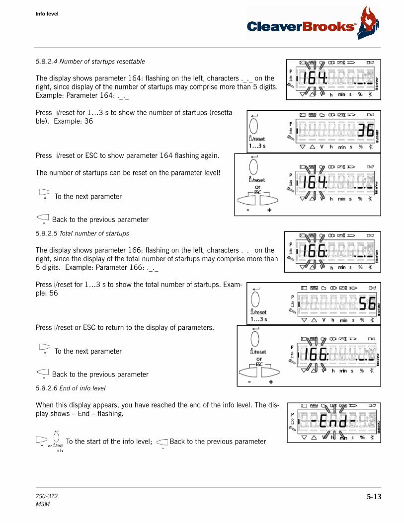
Info level
5.8.2.4 Number of startups resettable
The display shows parameter 164: flashing on the left, characters ._._ on the right, since display of the number of startups may comprise more than 5 digits. Example: Parameter 164: ._._
Press i/reset for 1…3 s to show the number of startups (resetta-ble). Example: 36
Press i/reset or ESC to show parameter 164 flashing again.
The number of startups can be reset on the parameter level!
To the next parameter
Back to the previous parameter
5.8.2.5 Total number of startups
The display shows parameter 166: flashing on the left, characters ._._ on the right, since the display of the total number of startups may comprise more than 5 digits. Example: Parameter 166: ._._
Press i/reset for 1…3 s to show the total number of startups. Exam-ple: 56
Press i/reset or ESC to return to the display of parameters.
To the next parameter
Back to the previous parameter
5.8.2.6 End of info level
When this display appears, you have reached the end of the info level. The dis-play shows – End – flashing.
To the start of the info level; Back to the previous parameter
750-372M5M
5-13

Commissioning - LMV/RWF50 Controls
Press i/reset for >3 s or ESC to return to the normal display. OPErAtE appears for a short moment.
When this display appears, you are back on the normal display and you can change to the next level mode.
5.9 - LMV Service level
The service level is used to display information about errors including the error history and information about the LMV control.
Note: When on the service level, you can press - or + to display the next or the previous parameter. Instead of pressing +, you can also press i/reset for <1 s.
Note: Press ESC or i/reset for >3 s to return to the normal display.
Note: No change of values on the service level. If characters are displayed by the parameter, the value may consist of more than 5 digits. Press i/reset for >1 s and <3 s to display the value. Press i/reset for >3 s or ESC to return to the selection of the parameter (flashing).
5.9.1 - Display of service level
Press i/reset for >3 s until SEr appears. When releasing/reset, you are on the service level.
No. Parameter Service level 954 Flame intensity 960 Actual flow rate (fuel throug hput in m³/h, l/h, ft³/h, gal/h) 121 Manual output
Undefined = automatic operation 922 Incremental position of actuators
Index 0 = fuel Index 1 = air
936 Standardized speed 161 Number of faults701 .
.
.
725
Error history: 701-725.01.Code
5-14 750-372M5M

Parameter level
5.9.2 - Display of service values (example)
5.9.2.1 Number of faults
The display shows parameter 161: flashing on the left, the number of faults that occurred thus far on the right 0. Example: Parameter 161: 0
Press ‘+’ or i/reset for the next parameter and ‘-’ for the previous parameter.
5.9.2.2 Intensity of flame
The display shows parameter 954: flashing on the left. On the right, the flame’s intensity is displayed as a percentage. Example: 954: 0.0
Press ‘+’ or i/reset for the next parameter and ‘-’ for the previous parameter.
5.9.2.3 End of service level
When this display appears, you have reached the end of the service level. Dis-play – End – appears flashing.
Press ‘+’ or i/reset for the next parameter and ‘-’ for the previous parameter.
Press ESC to return to the normal display. OPErAtE appears for a short moment.
When this display appears, you are back on the normal display and you can change to the next level mode.
5.10 - Parameter level
The parameters stored in the LMV control can be displayed or changed on the parameter level. A password is required.
5.10.1 - Entry of password
The service password consists of 4 characters.
Caution! Parameters and settings may only be changed by qualified personnel. If parameters are changed, respon-sibility for the new parameter settings is assumed by the person who – in accordance with the access rights – has made parameter changes on the respective access level.
! Caution
750-372M5M
5-15

Commissioning - LMV/RWF50 Controls
Press button combination F - A to display CodE.
When releasing the buttons, 7 bars appear, the first of which flashes.
Press - or + to select a number or letter.
Press /reset to confirm the value. The value entered changes to a minus sign (–). The next bar starts flashing.
After entry of the last character, the password must be con-firmed by pressing i/reset. Example: Password consisting of 4 characters.
As a confirmation of correct entry, PArA appears for a maximum of 2 seconds.
For entry of passwords or burner IDs, the following numbers and letters can be used:
5-16 750-372M5M

Parameter level
5.10.2 - Entry of burner identification
The burner’s identification is entered like a password (character by character), but from right to left and ending with «_».
Parameter 113: flashes. Press i/reset to go to editing mode.
You are on the display for undefined burner identification. 8 bars appear.
Press - or + to select a number. Example: Number 3 flashes.
= 1
= A
= L
= 2
= b
= n
= 3
= C
= o
= 4
= d
= P
= 5
= E
= r
= 6
= F
= S
= 7
= G
= t
= 8
= H
= u
= 9
= I
= Y
= 0
= J
750-372M5M
5-17

Commissioning - LMV/RWF50 Controls
Press i/reset to confirm the value. Make the entry number by number.
Press - or + to select the next number. Example: Number 9 flashes.
After entry of the last number, burner identification must be con-firmed by pressing i/reset.
The display no longer flashes. Example: Burner identification 9993
Press ESC to return to the parameter level. PArAmeter 113: for burner identifi-cation.
5-18 750-372M5M

Parameter level
5.10.3 - Change of service password
Parameter 041: flashes. Press i/reset to go to level c: for password changes.
Letter n: for new. Proceed as described in chapter Entry of password and enter the new password (4 characters). After entry of the last character, the password must be confirmed by pressing i/reset.
Letter r: for repeat. Proceed as described in chapter Entry of password and repeat entry of the new password. After entry of the last character, the password must be confirmed by pressing i/reset.
SEt confirms that the new password has been saved.
Parameter 041: flashes again.
5.10.4 - Using the parameter level
The parameters stored in the LMV unit can be displayed and changed on the parameter level. Normally, all parameters have been set at the factory – with the exception of those for air-fuel ratio control. A description of parameter level 400, which is used for setting the fuel-air ratio curve, is given in chapter below.
750-372M5M
5-19

Commissioning - LMV/RWF50 Controls
5.10.5 - Structure of parameter levels
Air-fuel ratio control curves(primary setting)
Entering the password
Basic Unit
Internal parameter(password level)
Air-fuel ratio control
Actuator
Error history
Process data
/reset
/reset
/reset
/reset
/reset
/reset
/reset
/reset
5-20 750-372M5M

Parameter level
5.10.6 - Parameters without index, with direct display
Using the example of parameter 208: Program stop
PArAmeter level 200: for basic units.
Press i/reset to go to menu level 200:
Press + to select «Program stop». Display: Parameter 208: flashes, value 0 does not.
Press i/reset to go to editing mode. Display: Program stop time set Here: Value 0 corresponding to program stop deac-tivated.
Press - or + to select the required program stop time. 0 = deactivated 1 = PrePurgP (Ph24) 2 = IgnitPos (Ph36) 3 = Interv1 (Ph44) 4 = Interv2 (Ph52) Example: 2 IgnitPos (Ph36)
Press i/reset to return to editing mode. The value set is adopted.
Note: To detect potential display errors, the value is displayed 1 place shifted to the right.
Press ESC to return to the parameter level.
Display: Parameter 208: flashes, value 0 does not.
750-372M5M
5-21

Commissioning - LMV/RWF50 Controls
Press ESC to return to the parameter level. PArAmeter 208: flashes, value 2 does not.
Press ESC to return to the parameter level. PArAmeter 200: for basic units.
5.10.7 - Parameters without index, with no direct display (with parameters having a value range >5 digits)
Using the example of parameter 162: Operating hours reset-table
PArAmeter level 100: for general. Press i/reset to go to menu level 100.
Press + to select «Operating hours resettable». Display: Parameter 162: flashes, characters ._._ do not.
Press i/reset to go to editing mode. Display: 123457
You can press - or + to set the number of operating hours to 0. Display: Operating hours 0 flashes.
5-22 750-372M5M

Parameter level
Press ESC to return to the parameter level. PArAmeter 100: for general.
Press i/reset to return to editing mode. The value set is adopted.
Note: To detect potential display errors, the value is displayed 1 place shifted to the right.
Press ESC to return to the parameter level.
Display: Parameter 162: flashes, charac-ters ._._ do not.
750-372M5M
5-23

Commissioning - LMV/RWF50 Controls
5.10.8 - Parameters with index, with direct display
Using the example of parameter 501: No-flame positions fuel actuator
PArAmeter level 500: for air-fuel ratio control.
Press i/reset to go to menu level 500:. Display: Parameter 501. flashes, index 00: and value 0.0 do not.
Press i/reset to go to the index. Display: Parameter 501. does not flash, index 00: flashes, value 0.0 does not.
Press - or + to select the required index. .00 = home position .01 = prepurge position .02 = postpurge position Display: Index 01: for prepurge position flashes, value 0.0 does not.
Press i/reset to go to editing mode. Display: Value 0.0
Press - or + to select the required prepurge position. Example: 1.0
Press i/reset to return to editing mode. The value set is adopted.
Note: To detect potential display errors, the value is displayed 1 place shifted to the right. Display: Value 1.0
Press ESC to return to the index.
Display: Parameter 501. does not flash, index 01: flashes, value 0.0 has not changed and does not flash.
5-24 750-372M5M

Parameter level
Press ESC to return to the index. PArAmeter 501: does not flash, index 01: flashes, value 1.0 does not.
Press ESC to return to the parameter level. Display: Parameter 501 flashes, index 00: and value 0.0 do not.
Press ESC to return to the parameter level. PArAmeter 500: for air-fuel ratio control.
5.10.9 - Parameters with index, with no direct display
Using the example of parameter 701: Errors
HIStorie 700: for error history. Press i/reset to go to the parameter level.
Press + to select parameter 701. Display: Parameter 701. flashes, index 01: and value 201 do not.
Press i/reset to go to index 01:. Display: Parameter 701. does not flash, index 01: flashes, value 201 does not.
To the next index Back to the previous index
Press + to select the index: .01 = error code .02 = diagnostic code .03 = error class .04 = error phase .05 = startup counter .06 = out-put. Example: Parameter 701., index 05: for startup counter, diagnos-tic code ._._
750-372M5M
5-25

Commissioning - LMV/RWF50 Controls
Press i/reset to go to display mode. Display: Value 56
Press ESC to return to the index. Display: Parameter 701. does not flash, index 05: flashes, characters ._._ do not.
Press ESC to return to the parameter level. Display: Parameter 701. flashes index 05: does not, characters ._._do not.
To the next older error
Parameters cover the period of time back to the last error since history was deleted (max. to parameter 725.). Example: Parameter 725., index 01:, error code 111
To the next parameter Back to the previous parameter
When this display appears, you have reached the end of the error history index. Display – End – appears flashing.
Press ‘+’ or i/reset for the next parameter and ‘-’ for the previous parameter.
When this display appears, you have reached the end of the error history. Dis-play – End – appears flashing. Press ESC to return to the parameter level. HISt 700: for error history
Press ‘+’ or i/reset for the next parameter and ‘-’ for the previous parameter.
Note: If you wish, you can delete the error history via parameter 130. To delete the display, set the parameter to 1 and then to 2. The error history is deleted when the parameter has returned to 0.
5-26 750-372M5M

Initial Startup
5.11 - Initial Startup
5.11.1 - VSD/Fan Speed settings
The Variable Speed Drive is pre-configured at the factory. Should it become necessary to change the drive’s con-figuration, VSD parameters can be viewed and changed using the drive’s integral keypad/display. See APPENDIX C - Variable Speed Drive Parameters for parameter list; if necessary refer also to the Allen-Bradley PowerFlex 525 user manual.
Because the input is determined by the fan speed, fan speed settings may have to be modified for the particular application, for high altitudes, or when using direct vent combustion. The default fan speed settings are intended for typical applications for the various boiler sizes. Please contact your authorized Cleaver-Brooks representative for proper settings in high altitude and direct vent combustion applications.
5.11.2 - Gas Train and Piping
The M5M burner is equipped with a combination servo-regulated gas valve and venturi mixing unit. The gas valve consists of a single body and regulating actuator with safety shutoff. Combustion airflow is directly proportional to the speed of the fan. The airflow creates a drop in pressure due to the venturi effect. The modulating controller of the valve actuator senses air pressure change and accordingly brings about a change in the gas flow proportional to the air pressure. The gas follows the airflow in a set ratio, so that fuel always matches the air as the burner firing rate increases or decreases.
1. Check the gas delivery system to be sure it is properly piped and wired. 2. Review available gas supply pressure to ensure that it is compatible with the M5M’s gas train and regulator.
Refer to Table 4-1 for minimum required supply pressure and maximum allowable supply pressure. 3. To bleed air from the supply pipe, open the manual gas shut off valve upstream of the burner gas train and
bleed air from the piping by loosening the union in the upstream piping. 4. The burner and its gas connection must be leak tested before placing the boiler into operation.5. Gas Pressure Regulator - Using the adjusting screw on the main gas regulator, adjust the gas valve inlet
pressure to within the recommended levels in Table 4-1.
Before initial startup, check for blockages in the flue venting or vent terminations. Inspect the burner and furnace for any contamination or blockages.
! Warning
750-372M5M
5-27

Commissioning - LMV/RWF50 Controls
Table 5-1 M5M Gas Pressure Requirements
*Upstream regulator required for higher gas supply pressures
5.11.3 - Power-Up
1. Ensure the boiler is properly wired for the available power supply. Refer to the wiring diagram provided withthe boiler.
2. Verify the voltage to ensure it is within specifications.
5.11.4 - Operation Check: Gas Valve, Gas Pressure Switches, Combustion Air Proving Switch, Ignition Fail
Before initial firing of the burner, the gas valve, Low Gas Pressure Switch (LGPS), High Gas Pressure Switch (HGPS), and Combustion Air Proving Switch (CAPS) should be checked for proper operation.
• Before proceeding, review Section 5.3 - Control Setpoints for initial LGPS, HGPS, and CAPS settings.
Note: Close the downstream manual gas shut-off valve before checking pressure switches and CAPS.
FIGURE 5-1. Premix Burner Technology - Full Modulation
Boiler Model
Minimum pressure required at gas train connection
(inches WC)
Max. pressure*
2000 17” WC 2 PSI2500 17” WC 2 PSI3000 17” WC 2 PSI3500 21” WC 2 PSI4000 21” WC 2 PSI4500 24” WC 2 PSI5000 28” WC 3 PSI6000 28” WC 3 PSI
5-28 750-372M5M

Initial Startup
LGPS
1. To check the Low Gas Pressure Switch, first close the upstream manual shutoff valve (both manual shutoffvalves should now be closed).
2. Start the burner and wait 10 seconds during purge for CAPS to be made.3. Turn the LGPS setting to maximum.4. Open the test cock to bleed the gas line.5. The controller should lock out.6. Reset the controller and change the LGPS setting back to minimum to proceed.
CAPS
1. Initiate burner sequence. 2. During purge cycle, set Combustion Air Proving Switch to its maximum setting.
The controller should lock out on an airflow failure.
Note: If the CAPS fails to open even when set to maximum, test by disconnecting the low-pressure line to the switch and initiating burner sequence. The switch should now break during the purge cycle. Reconnect low-pressure side after a suc-cessful CAPS check.
3. Following a successful CAPS check, dial the CAPS back to its minimum setting and reset the controller.
HGPS and GAS VALVE
1. Open the upstream manual shutoff valve and wait a few moments for gas pressure to rise.2. Lower the switch setting to minimum.3. Initiate burner sequence. During the main flame establishing period, verify gas valve LEDs energize, indicating both
safety shutoff valves open.4. The controller should lock out on an interlock failure.5. Reset controller.6. Open the downstream manual shutoff valve to clear the lockout condition.
Dial the HGPS back to its maximum setting and reset.
IGNITION FAILURE CHECK
1. Close the downstream shutoff valve and attempt to start the burner. The controller should lock out on anignition failure.
After making the above operation checks, re-open the downstream manual shut-off valve.
5.11.5 - Pilot Fail Check
Close the gas pilot shutoff valve. Also shut off main fuel supply. Attempt to start the burner. There should be an ignition spark, but no pilot flame. The controller will lock out, indicating pilot failure.
Reset the controller, open the pilot shutoff valve, and re-establish fuel supply before continuing.
5.11.6 - Low Water Cutoff Check
1. Hold down the LOW WATER RESET-TEST switch for 3 seconds.2. Check display for low water fault message.
750-372M5M
5-29

Commissioning - LMV/RWF50 Controls
3. Press RESET-TEST switch once to reset.
5.11.7 - Low and High Fire Adjustments
All M5M boilers are factory tested firing natural gas at an altitude of 1000 ft ASL. Operating under different conditions may require re-adjustment of the gas valve.
FIGURE 5-3. Gas Valve adjustment
Refer to Appendix D or E depending on make of gas valve for further information on valve setup, operation, and testing.
5.11.8 - Modulation OFF point
Prior to setting combustion, the Modulation OFF point should be adjusted upward to avoid nuisance shutdowns while the burner is under manual control.
5-30 750-372M5M

Setting Combustion
5.12 - Setting Combustion
The display shows 400: flashing on the left, SEt appears on the right.
An unprogrammed unit or a unit whose operating mode has been reset or changed displays OFF UPr.
For initial commissioning, change to the parameter level. The set-tings can then be made on parameter level 400.
Press i/reset to select parameter 400 for initial commissioning and for setting air-fuel ratio control.
Press i/reset to go to the settings for air-fuel ratio control and parame-ter 201 for selecting the operating mode. 201: appears flashing.
750-372M5M
5-31

Commissioning - LMV/RWF50 Controls
5.12.1 - Setting curvepoints P0 and P9
Display P0 appears flashing. Curvepoint for ignition load.
Keep A depressed. You are now in setting P0 of air actuator A for ignition position P0.
Press simultaneously A and - or + to set ignition position P0 of the air actuator. Example: 22.0
Release A. The selected value is adopted. Example: 22.0
Keep F and A depressed. You are now in setting n0, speed n is for ignition position n0
Press simultaneously F and A and - or + to adjust speed n0 of the load controller. Example: 20.0
Release F and A. The selected value is adopted. Example: 20.0
To the next curvepoint
Press ‘+’. P9 appears flashing. Curvepoint for high-fire. Same procedure as with P0. Note: If ‘-’ is pressed first, the display jumps to 90!
5-32 750-372M5M

Setting Combustion
To the next curvepoint Back to the previous curvepoint
Press ‘+’. The display shows “run” (indicating the unit is ready for setting the curve parameters).
Note: When pressing i/reset, you are given the choice of proceeding with ”warm settings” or, by pressing ESC, with ”cold settings”.
5.12.2 - Warm settings for modulating mode
Note: With “warm settings”, the burner is started up after pressing the Info button. Air-fuel ratio control can now be accurately set while the flame is present. When traveling along the precalculated curve to high-fire point P9, all intermediate curvepoints (P2…P8) must be set. Automatic operation is released when – after reaching P9 – the curve settings are quit by pressing ESC. If the curve settings are aborted earlier (ESC or shutdown due to fault), start prevention OFF UPr continues to be active until all points are set. If required, the gas pressure can be set at the high-fire point. In case the gas pressure is changed, all points must be checked by traveling along the curve downward and – if required – must be readjusted.
When “run” is displayed, the unit is ready for setting the combustion curve parameters.
When there is a request for heat.
Note: If, during the time the curve is parameterized, an error occurs which leads to safety shutdown, param-eterization of the curve is quit.
750-372M5M
5-33

Commissioning - LMV/RWF50 Controls
Phase Standby (stationary)
Phase Fan ramp up (fan motor = ON, safety valve = ON)
Phase Traveling to prepurge position
Phase Prepurging
Phase Traveling to ignition position
Wait until the burner is operating and symbol or is no longer high-lighted! The startup sequence stops in phase 36 Traveling to ignition position. The ignition position can be adjusted under cold conditions.
Ignition position P0 can only be set after symbol or is no longer highlighted. Keep A depressed, and for VSD F and A.
Press - or + to adjust the value. When symbol or is no longer highlighted, the next curvepoint P1 can be selected with +.
5-34 750-372M5M

Setting Combustion
Phase Traveling to ignition position
Phase Preignition
Phase 1st safety time (ignition transformer ON)
Phase 1st safety time (ignition transformer OFF), preignition time OFF
Phase Interval 1
Ignition position P0 can only be set when symbol or is no longer highlighted. For fuel, keep F depressed, for air A, and for VSD F and A. Press - or + to adjust the value. When symbol or is no longer highlighted, the next cur-vepoint P1 can be selected with + .
Low-flame position P1 can only be set when symbol or is no longer highlighted. The value is adopted from P0. For fuel, keep F depressed, for air A, and for VSD F and A Press - or + to adjust the value. When symbol or is no lon-ger highlighted, the next curvepoint P2 can be selected with + .
To the next curvepoint Back to the previous curvepoint
750-372M5M
5-35

Commissioning - LMV/RWF50 Controls
When changing from P1 to P2 for the first time, curvepoints P2…P8 automati-cally calculated and saved. CALC appears for a short moment.
Note: Curvepoints P2 to P8 are automatically computed as a straight line between P1 and P9.
High-fire position P9 can only be set when symbol or is no longer highlighted. If required, readjust the gas pressure. For fuel, keep F depressed, for air A, and for VSD F and A Press - or + to adjust the value. When symbol or is no longer highlighted, the next curvepoint P8 can be selected with - .
After setting the high-fire point (P9), either a change to parameter 546 (automatic operation) can be made (ESC) or all curvepoints can be run through in the reverse order. If the gas pressure is changed, all curvepoints must be checked and – if required – readjusted.
The maximum capacity is displayed. If the display shows - - - -, the maximum capacity has not yet been specified. The system can be run up to 100%. You can press /reset to go to editing mode, enabling you to change the maximum capacity.
To the next parameter
The minimum capacity is displayed. If the display shows - - - -, the minimum capacity has not yet been entered. The system can be run down to 20%. You can press i/reset to go to editing mode, enabling you to change the minimum capacity.
Completing parameterization of the curve Back to the previous parameter
When symbol ? or ? is no longer highlighted, you can press ESC a second time.
The warm settings for air-fuel ratio control by the LMV37.4... are now completed.
5-36 750-372M5M

Setting Combustion
5.12.3 - Editing the curvepoints
Note: To check the change on the burner, a curvepoint change in the cold settings necessitates a new approach of all curvepoints in the warm settings. After changing the curvepoint, OFF UPr appears on the nor-mal display of the AZL2…
To the next curvepoint To select the curvepoint
The selected curvepoint is displayed.
Keep F depressed. The fuel actuator has been selected for editing.
Keep F depressed and press - or + to adjust the fuel actua-tor. In the case of warm settings, the actuator follows directly the adjustments made. The changes are saved.
After releasing F , the curvepoint is selected again.
Keep A depressed. The air actuator has been selected for editing
Keep A depressed and press - or + to adjust the air actuator. In the case of warm settings, the actuator follows directly the adjustments made. The changes are saved.
After releasing A, the curvepoint is selected again.
750-372M5M
5-37

Commissioning - LMV/RWF50 Controls
To the next curvepoint Back to previous curvepoint
5.12.4 - Interpolation of curvepoints
Identification of start for setting the curve parameters.
Example 1 = gas modulating
P5 shall now be changed:
Keep F or A depressed. Example: F
5-38 750-372M5M

Setting Combustion
Press - or + to change the value as required. Example: 50.0
Press - or + to change the value as required. Example: 00.0
Release F or A . The required value is adopted. Example: P5:50.0:46.0
Keep + depressed for >3 s. CALC appears.
The display jumps to P6.
All curvepoints from P5 to P9 have now been automati-cally recalculated (linear interpolation):
Keep ‘-’ depressed for >3 s. CALC appears.
The display jumps to P4.
750-372M5M
5-39

Commissioning - LMV/RWF50 Controls
All curvepoints from P1 to P5 have now been automatically recalcu-lated (linear interpolation):
If it is not only the current curvepoint that shall be changed, but all other curvepoints in the direction of travel as well, a new straight line from the current curvepoint to P9 (press + ) or P1 (press - ) can be calculated by a long push on - or + .
Note: Due to interpolation, a number of curvepoints change. To be able to make a check on the burner itself, the changed curvepoints must be approached in the warm settings. If these curvepoints have not yet been completely approached, OFF UPr appears on the normal display of the AZL
5.13 - Commissioning: Final Steps
After combustion setup the following procedures should be performed before placing the biiler into service.
5.13.1 - Limit Controls Check
Steam Boilers
The operating (OLC) and high pressure limit (HLC) controls areexternally mounted to the control panel. The setting of the OLC should be slightly higher than the configured set point plus the hysteresis off value set in the controller. The setting of the HLC should be slightly higher than the OLC. For example: set point = 100.0 psig, Hysteresis Off = 5.0 psi; OLC could be set to 110 psig, HLC set to 120 psig. Specific settings are determined by application
5-40 750-372M5M

Commissioning: Final Steps
and system control scheme.The OLC and HLC can be tested while the boiler is producing steam by adjusting the switch setting downward. A lockout should result when the switch setting is at or just below the current steam pressure. Readjust each switch (and reset HLC) after testing.
Hot Water Boilers
The Modulation Off (operating limit) and High Limit functions can be tested while the boiler is operating by adjusting the respective setting downward and allowing the boiler outlet temperature to rise. The Modulation Off point is the sum of the Modulating setpoint and the Hysteresis Off value. The Modulation On point is the setpoint minus the Hysteresis On value.
When the boiler’s outlet temperature exceeds either of these settings, the boiler will shut down. When the operating limit is exceeded, the boiler will automatically recycle upon the outlet temperature dropping below the on point. When the High Limit is exceeded, a lockout should result requiring a manual reset of the control after the temperature has dropped below the high limit setting.
Before testing the High Limit, temporarily set the Modulation OFF point higher than the High Limit setting.
Restore Modulation OFF and High Limit to operational settings after testing.
Specific settings are determined by application. Maximum High Limit for Model M5M is 250 deg F.
5.13.2 - Post start-up checkout procedure
1. Ensure proper air venting to expansion tank (hot water units).
2. Verify the ability of the flame system to detect and respond to a loss of flame. This can be done by removingthe flame sensor cable. For a successful test the boiler should shut down and the gas safety shutoff valveclose with the display indicating a lockout condition. Reconnect the cable to the flame detector.
3. Set high gas pressure switch to 50% higher than operating gas pressure at low fire. Set low gas pressureswitch to 50% lower than operating gas pressure at low fire.
4. Check the draft on the outlet stack on each boiler, compare to acceptable limits (-.25 to +.25” W.C.) andrecord in start up form. Operating outside of acceptable limits could result in light off and flame failureproblems.
5. Switch to automatic operation and monitor flue gas to ensure consistent excess air.6. Reassemble all panels and covers that were removed and replace any plugs that were removed to check gas
pressure.7. Verify gas pressures remain within limits shown in Table 4-1.
8. Provide instructions to owner and operators on operation, safety and maintenance of the equipment.9. Provide instructions to owner and operators on proper water treatment guidelines and procedures.
5.13.3 - Boil Out (new boilers)
See 3.6 — Boil Out of a New Unit
750-372M5M
5-41

Commissioning - LMV/RWF50 Controls
5.14 - RWF50 Modulating Control
The RWF50 is the burner modulation control for the M5M, and is where modulation setpoints are configured and stored.
5.14.1 - Burner Modulating Control Sequence
Area (1) Thermostat function active.
Area (2) The RWF50.3 as a modulating controller provides control to the adjusted setpoint. Angular positioning is ensured via the analog output in the form of a standard signal.
Area (3) If the actual value exceeds the upper switch-off threshold HYS3 in spite of the lowest heating stage, the controller switches the burner off (B). The controller only starts low-fire operation when the actual value falls below switch-on threshold HYS1 again. If the response threshold (q) is exceeded, the controller switches to high-fire operation (A).
5.14.2 - Burner Shutdown
In the event of a sensor failure at the analog input InP1, the controller cannot monitor the actual value. Burner shutdown will automatically be triggered to guard against overheating.
Functions:
- Burner off - 3-position output for closing the controlling element - Self-setting function is ended - Manual control is ended
5.14.3 - Predefined Setpoint
The setpoint is predefined within the selected setpoint limits via the buttons or the ACS411 software. Using an external contact, the setpoint can also be shifted or changed over.
A
5-42 750-372M5M

RWF50 Modulating Control
Depending on the function selected for the binary input, the effective controller setpoint can change between set-point SP1 and setpoint SP2 or can be shifted by the amount of dSP. A contact at binary input D1 controls the changeover or shift.
The values for setpoints SP1, SP2 and dSP are to be entered at the operating level.
5.14.4 - Response Threshold (q)
The response threshold (q) defines for what period of time and how much the actual value is allowed to drop before the system switches to high-fire operation. An internal mathematical calculation using an integration func-tion determines the sum of all areas qeff = q1 + q2 + q3 as shown in the graph. This takes place only when the control deviation (x-w) falls below the value of switch-on threshold HYS1. If the actual value increases, integra-tion is stopped. If qeff exceeds the preset response threshold (q) (can be adjusted at the parameter level), this causes the second burner stage to switch on or – in the case of the 3-position controller/modulating controller – the controlling element to open. If the current boiler temperature reaches the required setpoint, qeff is reset to 0.
Contact at binary input D1Open: 0 Closed: 1
D1
DG
D1
DG
SP1
SP2 dSP
0 10 1
+
0 1 2
SPH oLHi/
SPL oLLo/
Active setpoint
Chapter 8.2 Controller Cntr
Function ofbinary input D1
bin1
None (factory-set)Setpoint changeoverSetpoint shift
012
750-372M5M
5-43

Commissioning - LMV/RWF50 Controls
In contrast to time-dependent switching on, load-dependent switching on offers the advantage of capturing the dynamics of the actual value. Also, monitoring the progression of the actual value during the change from low-fire to high-fire ensures low switching frequencies to reduce wear and to extend running times.
5.14.5 - Cold Start of Plant
Note! Functions Cold Start of Plant and Thermal shock protection (TSS) are interlocked. Only one function can be activated, but never both at the same time.
When a heating system is switched off for a longer period of time, the actual value will drop of course.
To achieve a faster control response, the controller immediately starts in high-fire operation as soon as the con-trol deviation (x-w) drops below a certain limit value.
This limit is calculated as follows: Limit value = 2 x (HYS1-HYS3)
In that case, the response threshold (q) is inactive, independent of operating mode and controlled variable (tem-perature or pressure).
5.14.6 - Thermal Shock Protection
Note! Functions Cold Start of Plant and Thermal shock protection (TSS) are interlocked. Only one function can be activated, but never both at the same time.
The controller comes with thermal shock protection (TSS) deactivated; it can be activated at the configuration level.
The function is automatically activated when the actual value drops below the adjustable limit value rAL (exceeds the adjustable limit value with the cooling controller). In that case, the setpoint is approached via a ramp function. Gradient and slope of the ramp rASL are adjustable. The setpoint ramp has a symmetrical toler-
q qq
q
Temperature (°C)
5-44 750-372M5M

RWF50 Modulating Control
ance band toLP. If, during the startup phase, the actual value leaves the tolerance band, the setpoint ramp is stopped until the actual value returns to a level within the tolerance band. The startup phase is ended when the setpoint of the ramp function reaches the final setpoint SP1.
Note! When thermal shock protection (TSS) is active, the controller operates in low-fire operation. The response threshold (q) is active.
tt1 t2
SP1
toLPrAL
t3 t4
Temperature
Figure 15: Thermal shock protection (TSS) Key
Setpoint (w)
Actual value (x)
750-372M5M
5-45

Commissioning - LMV/RWF50 Controls
5.15 - RWF50 Operation
5.15.1 - RWF50 Display and Buttons
The two 7-segment displays (red and green) show hyphens and all LEDs light up for about 5 seconds. The upper display (red) shows the actual value. The lower display (green) shows the setpoint.
When entering parameters, the parameter symbol at the bottom (green) and the set value at the top (red) appear. The actual value is shown on the upper display (red) and tUnE flashes on the setpoint display (green).
When the burner is under manual control, the setpoint display (green) shows HAnd flashing.
When switching power on, the displays show hyphens for about 5 seconds. The state that follows is called nor-mal display. Default display is the actual value and the current setpoint. Other values can be displayed at the configuration level or via PC software ACS411. Manual control, self-setting, the user, parameter and configura-tion levels can be activated from here.
Burner release
Operating mode 2-stage
Actual value display (red)and parameter value
USB-LED
Setpoint display (green)and parameter symbol
Enter button
Increase value
Controllingelement CLOSE
Controllingelement OPEN
ESC button
Decrease value
EnterESC
RWF50.x
5-46 750-372M5M

RWF50 Operation
5.15.2 - User Level
This level is started from the basic display. Setpoints SP1, SP2 or dSP can be altered. The values of InP (analog input) and Y (current angular positioning between 0...100%) can be displayed.
Changing the setpoints:
User level will time out after 180 seconds.
Basic display
Enter
7866
d11e
/021
2
Enter
Setpoint increase (factory-set)
SP1
Setpoint reduce (factory-set)
SP1
ESC >2 s
or timeout
Enter
OPr
EnterUser level OPr
SP1 SP2 dSPInP Y
Editable: , or Only display: ,
Navigation principle
EnterESC
One level back One level down
Next/previous parameter
PArA
ConF
* From the basic display, press Enter so that OPr appears
* Press Enter so that SP1 appears
* Press Enter and SP1 flashes
* Press or to adjust the required setpoint and press Enter to confirm
750-372M5M
5-47

Commissioning - LMV/RWF50 Controls
5.15.3 - Manual Control of Modulation
Note! Manual control can only be activated if a demand for heat exists (relay K1 is energized). If demand is met (relay K1 de-energized) during manual control, manual control is deactivated.
Note! When activating manual control, angular positioning is set to 0 until another entry is made.
* Change angular positioning by pressing or
* Adopt flashing new angular positioning by pressing Enter
Per default, the analog output delivers the current angular positioning.
* Return to automatic operation by keeping ESC depressed for 5 seconds
5-48 750-372M5M

RWF50 Operation
5.15.4 - Starting the self-setting function
5.15.5 - Software version & display test
Press to display the currently loaded RWF50 software version. Press again and all display segments and LEDs will light up. The display will flash for about ten seconds.
* Press + for 5 seconds
* Cancel with +
When t UnE stops flashing, the self-setting function has been ended.
The parameters calculated by the controller are automatically adopted!
Note! It is not possible to start t UnE in manual control or low-fire operation.
Start
Cancel
Enter + Enter +
750-372M5M
5-49

Commissioning - LMV/RWF50 Controls
5.16 - Parameterization
The PArA level accesses parameters for adjusting controller performance once the boiler has been placed into service. To access:
Parameters are shown on the lower (green) display and their respective values on the upper (red) display.
* Press Enter so that OPrr appears
* Press so that PArA appears
* Press Enter so that the first parameter of the parameter level is displayed
Parameter Display Value range Factory setting
Proportional band ¹ PPbb11 1...9999 digit 10
Derivative time ddtt 0...9999 s 80
Integral action time rr tt 0...9999 s 350
Dead band (neutral zone) ¹ ddbb 0.0...999.9 digit 1
Controlling element running time
tt tt 10...3000 s 15
Switch-on threshold Heating controller ¹ HHYYSS11 -1999...0.0 digit -5
Switch-off threshold stage II Heating controller ¹
HHYYSS22 0.0... HYS3 digit 3
Switch-off threshold Heating controller ¹ HHYYSS33 0.0...9999 digit 5
Response threshold q 0.0...999.9 0
¹ Setting of decimal place has an impact on this parameter
5-50 750-372M5M

Configuration
5.17 - Configuration
Most settings at the ConF level will have been made at the factory. Should thermal shock protection need to be activated it can be done here. Go to ConF>rAFC.
Parameter Value/ selection
Description
Function FnCt Function
0 Switched off 1 Gradient Kelvin/minute 2 Gradient Kelvin/hour
Note! With FnCt = 1 or 2, Thermal shock protection (TSS) is automatically activated as soon as the actual value drops below the adjustable absolute limit value r AL .
Ramp slope rASLRamp slope
0.0...999.9
Slope of ramp slope (only with functions 1 and 2)
Tolerance band ramp toLPTolerance band ramp
2 x |HYS1|=10...9999
Width of tolerance band (in K) about the setpoint (only with function 1 and 2)
Smallest possible factory setting: 2 x |HYS1| = 10 K To monitor the actual value in connection with thermal shock protection (TSS), a tolerance band can be laid about the setpoint curve. If the limit values are crossed, the ramp is stopped.
Note! In the event of a faulty sensor or manual control, the ramp function is stopped. The outputs behave the same way they do when the measuring range is crossed (configurable). Functions Cold start of plant and Thermal shock protection (TSS) are interlocked. Only one function can be activated, but never both at the same time.
Limit value rALRamp limit
0...250 Heating controller: If the actual value lies below this limit value, the setpoint is approached in the form of a ramp until final setpoint SP1 is reached.
750-372M5M
5-51

Commissioning - LMV/RWF50 Controls
5.17.1 - Display configuration
The information displayed is selectable for upper and lower displays. Also configurable are the timeout for return to basic display, decimal points, and locking of display access levels.
Parameter Value/
selectionDescription
Upper display diSUUpper display
Display value for upper display 0 Switched off 1 Analog input InP14 Controller’s angular positioning 6 Setpoint 7 End value with thermal shock protection
Lower display diSLLower display
Display value for lower display 0 Switched off 1 Analog input InP1 4 Controller’s angular positioning 6 Setpoint 7 End value with thermal shock protection
Timeout tout
0... 180... 255
Time (s) on completion of which the controller returns automatically to the basic display, if no button is pressed
Decimal point dECPDecimal point
0 No decimal place 1 One decimal place 2 Two decimal places If the value to be displayed cannot be shown with the programmed decimal
point, the number of decimal places is automatically reduced. If the measured value drops again, the number of decimal places is increased until the programmed value is reached
Locking of levels CodE
0 No locking 1 Locking of configuration level 2 Locking of parameter level 3 Locking of keyboard
5-52 750-372M5M

CHAPTER 6 Maintenance
6.1 - Overview
While each boiler is tested for correct operation before shipment from the factory, variable conditions such as burner characteristics of the fuel used and operating load conditions may require further adjustment after instal-lation to assure maximum operating efficiency and economy. Prior to placing the boiler into initial service, a com-plete inspection should be made of all controls, connecting piping, wiring and all fastenings such as nuts, bolts, and setscrews to be sure that no damage or mis-adjustments occurred during shipment and installation.
A well planned maintenance program avoids unnecessary down time or costly repairs, promotes safety and aids boiler code and local inspectors. An inspection schedule with a listing of procedures should be established. It is recommended that a boiler room log or record be maintained. Recording of daily, weekly, monthly, and yearly maintenance activities provides a valuable guide and aids in obtaining optimum service from Cleaver-Brooks equipment.
This chapter details adjustment and inspection procedures plus specialized maintenance where required. It can-not cover all of the phases involved in a complete maintenance program.
Even though the boiler has electrical and mechanical devices that make it automatic or semi-automatic in opera-tion, these devices require systematic and periodic maintenance. No “automatic” feature relieves the operator from the normal responsibilities of upkeep and maintenance.
Good housekeeping helps maintain a professional appearing boiler room. Only trained and authorized personnel should be permitted to operate, adjust, or repair the boiler and its related equipment. The boiler room should be kept free of all material and equipment not necessary to the operation of the boiler or heating system.
Being alert to an unusual noise, improper gauge reading, leaks, etc. can make the operator aware of a developing malfunction and prompt corrective action that may prevent extensive repairs or unexpected down time. Any steam, water, or fuel leaks should be repaired as soon as they are noticed. These are wasteful as well as hazard-ous. Include in the program preventive maintenance measures such as regularly checking the tightness of con-nections, locknuts, setscrews, packing glands, etc.
The air-fuel ratio should be checked often since this will alert the operator to losses in combustion efficiency which do not produce visible flame changes. Variations in fuel composition from one time to another may require
750-372M5M
6-1

Maintenance
readjustment of the burner. A combustion analysis should be used to adjust fuel input for maximum operating efficiency and economy.
See also Chapter 3 Waterside Care for additional maintenance requirements.
6.2 - Periodic Inspection
Insurance regulations or local laws normally require a periodic inspection of the pressure vessel by an authorized inspector.
Inspections of this type are usually, though not necessarily, scheduled for periods of normal boiler down time such as an off season. This major inspection can often be used to accomplish maintenance replacements or repairs that cannot easily be done at other times. This also serves as a good basis for establishing a schedule for annual, monthly, or other periodic maintenance programs.
While this inspection pertains primarily to the waterside and fireside surfaces of the pressure vessel, it provides the operator an excellent opportunity for detailed inspection of all components of the boiler including piping, valves, pumps, gaskets, refractory, etc. Comprehensive cleaning, spot painting or repainting, and the replace-ment of expendable items should be planned for and taken care of during this time. Any major repairs or replace-ments that may be required should also, if possible, be coordinated with this period of boiler shutdown.
Replacement spare parts, if not on hand, should be ordered sufficiently prior to shutdown.
Cleaver-Brooks boilers are designed, engineered, and built to give long life and excellent service on the job. Good operating practices and conscientious maintenance and care will obtain efficiency and economy from their oper-ation and contribute to long years of performance.
6.3 - Burner Maintenance
On an annual basis the boiler vessel and burner combustion system must be checked and cleaned. This work is to be carried out by an authorized Cleaver-Brooks Service Technician.
1. Close off the gas supply to the boiler and disconnect electrical power at the primary switch box.2. Remove the gas train and set aside.3. Disconnect the electrical connections to the blower assembly.4. Disconnect scanner, ignition, and pilot cables.5. Remove air filter (or direct vent coupling if supplied).6. Remove the nuts securing the blower to the adapter plate.7. The blower can now be removed.8. The burner head can be separated by removing the nuts and washers holding the adapter plate to the dry
oven.
6-2 750-372M5M

Reassembly
FIGURE 6-1. Burner/blower assembly
Check the burner head for any damage, burn marks or perforations. If damage is found replace the damagedparts. If the canister is in good condition clean out any dirt and contaminates with a vacuum cleaner inside andout, alternating with compressed air to dislodge any debris.
With the burner head and blower removed the fire side can be accessed for all service requirements.
Check ignition electrodes for deposits and proper gap. Clean or replace as needed.
Inspect the pressure vessel and combustion area for any damage or contamination. If dirt or contaminates arefound it is recommended that the tubes be washed with a high-pressure power washer.
6.4 - Reassembly
1. Assembly is the reverse of the above instructions.2. Burner gaskets should be replaced; see recommended spare parts list.3. Replace combustion air filter if dirty. Remove filter retaining rod and install new CB approved filter media; see
recommended spare parts list. Replace rod to hold filter in place.
6.5 - Ignition and flame detection systems
Ignition Electrode
The ignition electrode should be replaced annually, or more frequently if conditions require. Inspect theelectrode periodically for signs of fouling, displacement, or other damage.
Observe the dimensions below when replacing:
1/8” gap between ignitor electrode and ground electrode.
Label all wires prior to disconnection when servicing controls. Wiring errors can cause improper and dangerous operation. Verify proper operation after servicing.
DRY OVENBURNER CANISTER
ADAPTER PLATE
BLOWER ASSEMBLY
750-372M5M
6-3

Maintenance
1” from ignitor electrode to the burner canister.
Pilot and UV Scanner
Maintenance of the UV scanner consists of periodic inspection and cleaning. To inspect, unscrew the UV flame detector from the bracket. Check to ensure that the flame viewing lens is clear and free of dust or debris. Wipe with a clean rag if necessary.When replacing the scanner, verify an unobstructed line of sight through the scanner bracket to the burnercanister.
The M5M uses an interrupted gas pilot in lieu of direct spark ignition. Ensure pilot is installed with the holesfacing outward (towards the burner can).
FIGURE 6-2. Electrode spacing M5M
FIGURE 6-3. UV Scanner
1/8”
1 1/16
ENSURE HOLES ARE POINTED OUTWARDS
6-4 750-372M5M

Fireside Cleaning
6.6 - Fireside Cleaning
Soot and non-combustibles are effective insulators and if allowed to accumulate will reduce heat transfer to the water and increase fuel consumption. Soot and other deposits can be very moisture absorbent and may attract moisture to form corrosive acids which will deteriorate fireside metal.
Cleanout should be performed at regular and frequent intervals, depending upon load, type, and quality of fuel, internal boiler temperature, and combustion efficiency. A stack temperature thermometer can be used as a guide to cleanout intervals, since an accumulation of soot deposits will raise the flue gas temperature.
In extreme cases, soot or other combustion deposits may be present in the furnace area. These will have to be removed by brushing or scraping. Entry to this area is gained through the access door. Brush-out or vacuum any loosened deposits.
Inspect the refractory and repair or maintain as outlined in the refractory section.
The vent connection stack should be cleaned at regular intervals. Commercial firms are available to perform this work. The stack should be inspected for damage and repaired as required.
The fireside should be thoroughly cleaned prior to any extended lay-up of the boiler. Depending upon circum-stances, a protective coating may be required.
6.7 - Preparation for Extended Lay Up
A boiler used for heating or seasonal loads or for stand-by service may have an extended period of non-use. Spe-cial attention must be given so that neither waterside nor fireside surfaces are allowed to deteriorate from corro-sion.
FIGURE 6-4. Pilot Tube
IGNITION ELECTRODE
PILOT
750-372M5M
6-5

Maintenance
There are two methods of storage — wet and dry. Your water consultant or feedwater treating company can rec-ommend the better method, depending upon circumstances in a particular installation. Section VII of the ASME Code also contains information relating to laying up a boiler.
6.7.1 - Dry Storage
Dry storage is generally employed when the boiler will be out of service for some time or when freezing tempera-tures may occur. In this method, the boiler must be thoroughly dried, since any moisture will cause corrosion. Both waterside and fireside surfaces must be clean of all scale and deposits, soot, etc. Steps must be taken to eliminate moisture by placing moisture absorbing material, such as quicklime or silica-gel, on trays inside the drums and furnace. These trays should not be completely filled with the material, so that the corrosion liquid gathered in them does not overflow onto the boiler surfaces. Refractories should be brushed clean and wash-coated. Fireside surfaces may be sprayed or coated with an anti-corrosive material. All openings to the pressure vessel must be shut tightly. Feedwater and steam valves should be closed. Damper and vents should be closed to prevent air from reaching fireside surfaces. Periodic inspection must be made and the absorption materials renewed.
Care Must be taken to remove all of the moisture absorbing material before any attempt is made to refill the boiler. Serious damage can result otherwise. As a precaution it is recommended that warning signs be conspicu-ously posted. These signs can be similar to the following:
6.7.2 - Wet Storage
Wet storage is generally used for a boiler held in standby condition or in a case where dry storage is not practical. The possibility of freezing temperatures must be considered. Care must be taken to protect metal surfaces. Vari-ables preclude definite recommendations, however, it is suggested that after the vessel is drained and cleaned that it be refilled to overflowing with treated water. If deaerated water is not available, the boiler should be fired to boil the water for a short period of time. Additional chemicals may be suggested by the water consultant to minimize corrosion. Internal water pressure should be maintained at greater than atmospheric pressure. Nitrogen is often used for this purpose. Fireside surfaces must be thoroughly cleaned and refractories should be wash-coated. It is advisable, if feasible, to occasionally circulate the water to prevent stratification and to insure that fresh inhibitor is in contact with all surfaces. If additional chemicals are added for this idle period, more frequent blowdowns may be required when the boiler is returned to service to rapidly reduce the chemical composition to normal operating levels.
During storage, steps should be taken to protect the exterior components from the possibility of rust or corrosion. These parts should be coated with a rust inhibitor and protected from moisture and condensation. Operating controls, regulators. valves, etc. should be drained and dried. Electrical equipment should likewise be protected. Keeping the control circuit energized may prevent condensation from forming in the control cabinet or on the flame safeguard control.
Moisture absorption material has been placed in the waterside and furnace areas of this boiler. This material must be removed before any water is placed in the boiler and before the burner is fired. Inspect periodically and replace with fresh and/or regenerated materials.
Important!
6-6 750-372M5M

Troubleshooting
6.8 - Troubleshooting
Lockout Conditions
1. Observe lockout code and description - refer to Falcon appendix if necessary.2. After determining lockout condition, investigate possible causes.3. When cause is diagnosed, remedy condition.4. Reset control. Boiler should be able to start normally.5. If lockout recurs, further investigation is required. Repeat steps 1 through 4 as needed. If necessary, contact your CB
service representative for technical support.
EXAMPLE: Lockout 79 Outlet Temperature High Limit
1. Before resetting control to clear lockout, check for sufficient water flow through boiler. Possible sources of insufficient flow include closed water valves, insufficient pump speed, air trapped in boiler (inadequate air venting), or modulation set point and off point close to outlet high limit setting.
The Falcon system display/interface provides extensive boiler diagnostic data at the time of lockout that can help in determining the source of a problem. This information is accessed through the Lockout History.
2. Remedy condition that caused lockout to occur.3. Reset control by pressing <Clear Lockout> from the Lockout History screen.
Light-off Problems
Check electrode positioning according to Section 5.3 above.
The dimensions on the ignition electrodes are not easily adjustable - bending the rods can cause damage to theinsulation material. In addition, a bent electrode will return to its original shape when heated. If an ignitor orflame rod is out of specification, replacement is generally required. Clean or replace as necessary.
Also see Troubleshooting Chart below.
Troubleshooting Chart
Symptom/Fault Indication Possible Causes
Erratic display/controller behavior Faulty electrical ground - Check ground terminals in control panel. System should be grounded firmly to metal casing. External ground wiring may be necessary.
Touch screen not working properly Screen out of calibration - from Falcon home page, go to Setup/Advanced Setup/Diagnostics. Under “Touch Screen” press <Calibrate> and follow instructions on screen.
Burner can failure;High Gas Pressure lockouts
Incorrect gas pressure:
• Check regulated gas pressure and ensure it agrees with recommended. Check other equipment connected to gas main - regulator and gas supply piping sizings should be based on all appliances being ON.
• A dedicated, properly sized gas pressure regulator is required for each boiler.
• Customer connection should reduce to boiler gas train.
750-372M5M
6-7

Maintenance
6.9 - Extended Shutdown
When shutting down the boiler for an extended period of time, use the following general guidelines:
1. Turn the demand switch to the OFF position.2. Close all main fuel valves.3. If the boiler operates in a damp environment, cover electrical components in plastic to protect from moisture.
To restart after an extended period, follow the initial startup instructions in Chapter 4.
6.10 - Emergency Shutdown
In case of emergency, shut down the boiler by turning the demand switch to the OFF position. Shut off the mainmanual fuel shutoff valves on the fuel supply line. The unit can also be shut down with the main electricalpower disconnect. Inspect and troubleshoot the boiler before attempting to restart.
Lightoff problems • Wrong gas pressure. Check regulated gas pressure and ensure it agrees with recommended. Check other equipment connected to gas main - regulator and gas supply piping sizings should be based on all appliances being ON.
• Incorrect fan speed settings - increase fan speed by 100 RPM increments until successful lightoff occurs.
• Bad cable connections (ignition or flame rod)
• Electrodes fouled or improperly spaced - electrodes should be cleaned or replaced and spacing adjusted.
• Debris on burner canister. To clean the unit, remove the burner can and blow compressed air from the outside in. Vacuum up the residue.
• Electrical ground problem
Outlet Temperature High Limit lockout • Insufficient water flow through boiler - closed water valves, insufficient pump speed
• Air trapped in boiler
• Modulation set point and off point too close to outlet high limit setting
Interrupted Air Switch lockout • Blower not running
• Blocked blower inlet
• CAPS switch defective or improperly wired
Loss of flame • Debris on burner
• Blocked condensate drain
• Combustion improperly set
• Flame scanner soiled, obstructed, or out of position
Symptom/Fault Indication Possible Causes
6-8 750-372M5M

Water Level Controls
6.11 - Water Level Controls
The water level control has two float actuated internal switches. One switch is connected to the burner limit circuit and will stop the burner if a low water condition occurs. On a steam boiler the other switch is connected to the feed-water circuit to energize a water pump or feeder valve to maintain water at the proper operating level.
The control is of the automatic reset type and will remake the limit circuit when the water level is restored. Some applications require that a control be equipped with a manual reset mechanism that must be manually reset before the burner can be restarted. This is usually accomplished with the use of a second or auxiliary control with this feature.
Low water cutoff devices are generally set by the original manufacturer and no attempt should be made to adjust these controls to alter the point of low water cutoff or point of pump cut-in or cut-out. If a low water device should become erratic in operation or if its setting changes from previously estab-lished levels, check for reasons and correct, repair, or replace the device as required.
The need to periodically check water level controls cannot be over emphasized. Most instances of major boiler damage are the result of operating with low water.
On steam boilers the head mechanism of the low water cutoff device(s) should be removed from the bowl at least once a month to check and clean the float ball, the internal moving parts, and the bowl or water column.
At the same time, remove the pipe plugs from the column, tees or crosses to make sure the cross connecting pip-ing is clean and free of obstructions. Controls must be mounted in a plumb position for proper performance. Determine that piping is vertically aligned after shipment and installation and throughout the life of the equip-ment.
Water level controls normally function for long periods of time which may lead to laxity in testing on the assump-tion that normal operation will continue indefinitely. Testing of the controls, especially on steam boilers, should be followed on a definite planned schedule. The control’s operation may be checked by stopping the water sup-ply to the boiler while the burner is operating at low fire. While under constant attendance allow the water to lower at a normal rate. If a control does not break the circuit to stop the burner at the proper point then SHUT DOWN THE BURNER IMMEDIATELY. Repair or replace the control at once.
A scheduled blowdown of the water controls on steam units should be maintained.
On a hot water boiler it is impractical to perform daily and monthly maintenance of the low water cutoff devices. However, it is essential to remove the operating mechanism from the bowl annually or more frequently, if possi-ble, to check and clean the float ball, internal moving parts, and the bowl housing. Also check any cross connect-ing piping to make certain that it is clean and free of obstruction. It is not practical to blowoff or drain the low water cutoff devices, since the entire water content of the system would become involved. Many hot water sys-tems are fully closed and any loss of water will require make-up and additional feedwater treatment that might not otherwise be necessary.
750-372M5M
6-9

Maintenance
6.12 - Water Gauge Glass
A blowdown cock is provided on the lower gauge glass fitting and a daily blowdown is recommended. The glass should be removed every 3 months and checked, while cool, for etching, thinning, or damage. If any defects are found, replace the glass immediately to avoid the possibility of breakage in service. Do not over tighten water gauge glass fittings. Check try cocks and gauge cocks for freedom of operation and clean as required. Proper alignment of gauge glass cocks is essential to prevent mechanical strain on the glass.
6-10 750-372M5M

CHAPTER 7 Parts
Burner Assembly . . . . . . . . . . . . . . . . . . . . . . . . . . . . . . . . . . . . . . . . . . . . . . . . . . . . . . . . . . . . . . . .7-2
Gas Train . . . . . . . . . . . . . . . . . . . . . . . . . . . . . . . . . . . . . . . . . . . . . . . . . . . . . . . . . . . . . . . . . . . . .7-3
Pilot Train . . . . . . . . . . . . . . . . . . . . . . . . . . . . . . . . . . . . . . . . . . . . . . . . . . . . . . . . . . . . . . . . . . . . .7-5
Control Panel, Falcon Steam . . . . . . . . . . . . . . . . . . . . . . . . . . . . . . . . . . . . . . . . . . . . . . . . . . . . . . . .7-6
Control Panel, Falcon Hot Water . . . . . . . . . . . . . . . . . . . . . . . . . . . . . . . . . . . . . . . . . . . . . . . . . . . . .7-7
Control Panel, LMV Steam . . . . . . . . . . . . . . . . . . . . . . . . . . . . . . . . . . . . . . . . . . . . . . . . . . . . . . . . .7-8
Control Panel, LMV Hot Water . . . . . . . . . . . . . . . . . . . . . . . . . . . . . . . . . . . . . . . . . . . . . . . . . . . . . . .7-9
Pressure Controls 15#/150#/250# Steam . . . . . . . . . . . . . . . . . . . . . . . . . . . . . . . . . . . . . . . . . . . . . .7-10
Pressure Controls 350#/500# Steam . . . . . . . . . . . . . . . . . . . . . . . . . . . . . . . . . . . . . . . . . . . . . . . . .7-11
750-372M5M
7-1

Parts
7.1 - Burner Assembly
6
11
16
15
16 4 7 8 7 5
117
10
17DESCRIPTIONQTYITEMADAPTER, DRY OVEN TO BLOWER11
RETAINER, SIGHT PORT14TUBE, GAS PILOT15DRY OVEN ASSEMBLY16
GASKET, ELECTRODE 380-01032-00027ELECTRODE, DUAL, IGNITION380-01061-00018BURNER CAN110SCANNER ASSEMBLY - UV817-01743-000111SIGHT GLASS, PYREX851-00026-000115
SIGHT GLASS GASKET853-00213-000216
BURNER GASKET853-09355-000217
065-00879-000
090-09917-000279-00799-000
SEE TABLE
2000-3000 3500001-01570-000 001-01572-000
4000 4500-6000
ITEM 10 BURNER CANISTER 2000-2500 3000-3500 4000-4500 5000 6000380-01154-000 380-01131-000 380-01155-000 380-01159-000 380-01132-000
35
2
343
104
17
293
28
9
2000-3000
3500-6000
KIT, AIR FILTER880-06273-000128
DESCRIPTIONQTYITEM
VENTURI ASSEMBLY13GASKET, BLOWER INLET380-01129-00019
12
COMBUSTION AIR PROVING SWITCH817-03468-000112
BLOWER, COMBUSTION AIR129
BRACKET, SUPPORT008-09710-00012DESCRIPTIONQTYITEM
VENTURI048-00811-00013PLATE, ADAPTER059-11175-00014
12
COMB. AIR PROVING SW.817-03468-000112GASKET, BLOWER INLET380-01121-000110
O-RING853-01476-000117
BLOWER, COMB . AIR135
2000 2500 3000008-09852-000 008-09623-000
059-11174-000380-01121-000
SEE TABLE
ITEM 3 VENTURI 3500 4000 4500-6000 048-00895-000 048-00899-000 048-00897-000
4500-60003500-4000
880-06272-000
34 KIT, AIR FILTER1
SEE TABLE
SEE TABLE
ITEM 29 COMBUSTION AIR BLOWER
894-05675-000894-05722-000 894-05682-000 894-05682-0004500
894-05562-00060003500 4000
ITEM 35 COMBUSTION AIR BLOWER
880-02502-000
894-05558-000 894-05780-00030002000 2500
894-05702-000
2
2 1 BRACKET, SUPPORT, MOTORSEE TABLE
ITEM 2 MOTOR SUPPORT BRACKET
008-09710-000 008-09624-000 008-09711-00060003500 45004000 5000
5000
008-09624-000008-09849-000
7-2 750-372M5M

Gas Train
7.2 - Gas Train
DESCRIPTIONPART NOQTYITEMBRACKET, GAS TRAIN008-02352-00021BRACKET, M5 BASE RAIL STUB008-03333-00022ADAPTER, PIPE, 2" NPT. WITHOUT SHUTTER800-00102-00014ADAPTER, 1/8 BSPT (MALE) x 1/8" NPT (FEMALE)800-00103-00015ADAPTER, PIPE, 1-1/2" NPT. WITH SHUTTER, O-RING AND SCREWS800-00104-00016LGPS, 3-21"WC RANGE, MR, 1/4" NPT MOUNT817-02416-00017PRESSURE SWITCH, 3-21"WC RANGE, MR, 1/4" NPT MOUNT817-02420-00018LEAKAGE TEST COCK, 1/8" NPT.825-00239-00039REGULATOR, GAS PRESS918-00540-000133VALVE, GAS, 110VAC940-07482-000134BUTTERBALL VALVE, BRONZE, 1-1/2" NPT.941-01946-000235
22
35 1 33 1
11
35
34
64
21
95
7
8
9
9
2000-3000
DESCRIPTIONPART NOQTYITEM
ITEM
BRACKET, GAS TRAIN008-02352-00021BRACKET, M5 BASE RAIL STUB008-03333-00022ORIFICESEE TABLE13
3
ACTUATOR, SIEMENS SKP75.011U1797-07871-00016HGPS, 12-60"WC RANGE, MR, 1/4" NPT MOUNT817-02417-00017LGPS, 12-60"WC RANGE, MR, 1/4" NPT MOUNT817-02418-00018LEAKAGE TEST COCK, 1/8" NPT.825-00239-00019REGULATOR, GAS PRESS918-00540-000128TUBING, ALUMINUM, 3/8" O.D. x .035" WALL x 25-3/4" LG.939-00413-000129BUTTERBALL VALVE, BRONZE, 1-1/2" NPT.941-01946-000230VALVE BODY, 1-1/2" NPT, MOTORIZED, GAS949-00461-000131
22
4
30
330 28
6
11
9
24
16
29
21
87
31
3500-5000
ORIFICE, 0.81" I.D.ORIFICE, 0.935" I.D.
048-00896-000048-00906-000
3500-40004500-5000
BOILER SIZE DESCRIPTION
750-372M5M
7-3

Parts
(Gas Train continued)
7-4 750-372M5M

Pilot Train
7.3 - Pilot Train
DESCRIPTIONPART NOQTYITEMCOCK, GAS SERVICE, TEE HEAD, 1/2" NPT, BRONZE825-00178-00011
REGULATOR, GAS PRESSURE, 1/2" NPT, 2-6" WC918-00356-000114
VALVE, SOLENOID,1/2" NPT, NC, 0-50PSI948-00197-000116
1
14 16
750-372M5M
7-5

Parts
7.4 - Control Panel, Falcon Steam
ITEM QTY PART NO. DESCRIPTION1 3 019-01345-000 COVER, 1-1/2" W X 8" LG DUCT2 1 019-01345-000 COVER, 1-1/2" W X 12-1/2" LG DUCT3 1 019-01345-000 COVER, 1-1/2" W X 18" LG DUCT4 1 019-01345-000 COVER, 1-1/2" W X 20" LG DUCT5 1 118-03922-000 NAME PLATE, DEMAND REM-OFF-LOC6 1 826-00211-000 CABLE, UV SCANNER7 2 826-00344-000 CABLE, IGNITION8 1 832-00118-000 TRANSFORMER,IGNITION,115V PRI,10000V SEC,60 HZ9 2 832-00235-000 TRANSFORMER, 115v/25v10 1 832-01188-000 FUSE BLOCK, THREE POLE11 2 SEE TABLE FUSE, (PRIMARY)12 1 SEE TABLE FUSE, (SECONDARY)13 1 832-01951-000 DIN MOUNTING RAIL, 4-1/2" LG.14 1 832-01951-000 DIN MOUNTING RAIL, 20" LG.15 1 832-01951-000 DIN MOUNTING RAIL, 9" LG.16 1 832-02045-000 FUSE, 1 AMP, 5x20mm17 1 832-02051-000 FUSE, 2 AMP, 5x20mm18 2 832-02179-000 POWER SUPPLY, 10-12 VDC OUTPUT, 3.0 A, 115 VAC19 6 832-02248-000 RETAINING END ANCHOR20 73 832-02326-000 TERMINAL BLOCK21 3 832-02328-000 TERMINAL, GROUNDING22 4 833-03532-000 ELECTRICAL-RELAY, DPDT,115VAC COIL23 4 833-03534-000 BASE,RELAY,8-PIN,DIN RAIL MOUNTING24 1 833-10725-000 CONTROLLER, BOILER, STEAM25 1 833-04095-000 CONTROLLER, RELAY, LOW LEVEL, HWA/ALWCO26 1 833-05105-000 DISPLAY, SYSTEM INTERFACE27 4 836-01136-000 CONTACT BLOCK28 1 836-01148-000 SWITCH, SELECTOR, 3 POSITION29 3 848-00797-000 WIRING DUCT, 1-1/2" W X 2" H X 8" LG.30 1 848-00797-000 WIRING DUCT, 1-1/2" W X 2" H X 20" LG.31 1 848-00797-000 WIRING DUCT, 1-1/2" W X 2" H X 18" LG.32 1 848-00797-000 WIRING DUCT, 1-1/2" W X 2" H X 12-1/2" LG.33 1 848-01093-000 CABINET, NEMA 1, 30"H X 30"W X 8-5/8"D, W/SUB-PANEL34 2 848-01321-000 FUSE BLOCK, SINGLE POLE35 1 881-00348-000 LATCH, PLASTIC36 2 884-00078-000 TERMINAL, SCRULUG, #14 THRU #4 AWG37 1 SEE TABLE CONTROLLER, VSD38 3 SEE TABLE FUSE, (BLOWER)39 1 SEE TABLE TRANSFORMER, 500VA (CCT)
LIGHT PACKAGE/ALARM HORN OPTIONDESCRIPTIONPART NO.QTYITEMNAME PLATE, HIGH STEAM PRESSURE118-03922-000140NAME PLATE, POWER ON118-03922-000141NAME PLATE, LOW WATER118-03922-000142NAME PLATE, FUEL VALVE118-03922-000143NAME PLATE, HIGH WATER118-03922-000144LED LIGHT MODULE, GREEN881-00349-000145PILOT LIGHT, RED881-00350-000346LED LIGHT MODULE, RED881-00351-000347PILOT LIGHT, GREEN881-00352-000148PILOT LIGHT, AMBER881-00353-000149LED LIGHT MODULE, AMBER881-00354-000150PILOT LIGHT, WHITE881-00357-000151LED LIGHT MODULE, WHITE881-00358-000152LATCH, PLASTIC881-00348-000653NAME PLATE, ALARM118-03922-000154ALARM HORN817-03571-000155
26
44464753
40464753
54464753
41 51 52 53
43 48 45 53
42 49 50 53
5528 35 27 5
33
9
34
16
19
14
19
25
9
20
246
36
36
15
2322
19
2121
18
430
13
10
38
19 21 20 20 20
232
3
31
1 29
1 29
1
29
37
8
34
17
VSD SELECTION (380/480 VAC)MODEL MOTOR HP ITEM #37 ITEM #38 FUSE (AMPS)2000 2 833-10721-000 7/62500 2 833-10721-000 7/63000 3 833-10722-000 10/93500 3 833-10722-000 10/94000 5 833-10723-000 15/124500 5 833-10723-000 15/125000 5 833-10723-000 15/126000 7.5 833-10724-000 20
VSD SELECTION (575/600 VAC)MODEL MOTOR HP ITEM #37 ITEM #38 FUSE (AMPS)2000 2 833-10720-000 52500 2 833-10720-000 53000 3 833-10719-000 73500 3 833-10719-000 74000 5 833-10678-000 104500 5 833-10678-000 105000 5 833-10678-000 106000 7.5 833-10679-000 15
VSD SELECTION (208/240 VAC)MODEL MOTOR HP ITEM #37 ITEM #38 FUSE (AMPS)2000 2 833-10726-000 15/122500 2 833-10726-000 15/123000 3 833-10727-000 20/17.53500 3 833-10727-000 20/17.54000 5 833-10728-000 254500 5 833-10728-000 255000 5 833-10728-000 256000 7.5 833-10729-000 35
CCT SELECTIONMODEL ITEM #11 ITEM #12 ITEM #39208V 832-01810-000 832-01908-000 832-01801-000240V 832-01810-000 832-01908-000 832-01802-000380V 832-01809-000 832-01908-000 832-01910-000480V 832-01808-000 832-01908-000 832-01802-000575V 832-01805-000 832-01908-000 832-01911-000
33 39 12 11
7
7-6 750-372M5M

Control Panel, Falcon Hot Water
7.5 - Control Panel, Falcon Hot Water
ITEM QTY PART NO. DESCRIPTION1 3 019-01345-000 COVER, 1-1/2" W X 8" LG DUCT2 1 019-01345-000 COVER, 1-1/2" W X 12-1/2" LG DUCT3 1 019-01345-000 COVER, 1-1/2" W X 18" LG DUCT4 1 019-01345-000 COVER, 1-1/2" W X 20" LG DUCT5 1 118-03922-000 NAME PLATE, DEMAND REM-OFF-LOC6 1 826-00211-000 CABLE, UV SCANNER7 2 826-00344-000 CABLE, IGNITION8 1 832-00118-000 TRANSFORMER,IGNITION,115V PRI,10000V SEC,60 HZ9 1 832-00235-000 TRANSFORMER, 115v/25v10 1 832-01188-000 FUSE BLOCK, THREE POLE11 2 SEE TABLE FUSE, (PRIMARY)12 1 SEE TABLE FUSE, (SECONDARY)13 1 832-01951-000 DIN MOUNTING RAIL, 4-1/2" LG.14 1 832-01951-000 DIN MOUNTING RAIL, 20" LG.15 1 832-02045-000 FUSE, 1 AMP, 5x20mm16 1 832-02051-000 FUSE, 2 AMP, 5x20mm17 6 832-02248-000 RETAINING END ANCHOR18 55 832-02326-000 TERMINAL BLOCK19 3 832-02328-000 TERMINAL, GROUNDING20 1 833-03532-000 ELECTRICAL-RELAY, DPDT,115VAC COIL21 1 833-03534-000 BASE,RELAY,8-PIN,DIN RAIL MOUNTING22 1 833-03547-000 CONTROLLER, LWCO23 1 833-04097-000 FALCON CONTROLLER, HYDRONIC24 1 833-05105-000 DISPLAY, SYSTEM INTERFACE25 4 836-01136-000 CONTACT BLOCK26 1 836-01148-000 SWITCH, SELECTOR, 3 POSITION27 1 848-00797-000 WIRING DUCT, 1-1/2" W X 2" H X 12-1/2" LG.28 1 848-00797-000 WIRING DUCT, 1-1/2" W X 2" H X 20" LG.29 1 848-00797-000 WIRING DUCT, 1-1/2" W X 2" H X 18" LG.30 3 848-00797-000 WIRING DUCT, 1-1/2" W X 2" H X 8" LG.31 1 848-01093-000 CABINET, NEMA 1, 30"H X 30"W X 8-5/8"D, W/SUB-PANEL32 2 848-01321-000 FUSE BLOCK, SINGLE POLE33 1 881-00348-000 LATCH, PLASTIC34 2 884-00078-000 TERMINAL, SCRULUG, #14 THRU #4 AWG35 1 SEE TABLE CONTROLLER, VSD36 3 SEE TABLE FUSE, (BLOWER)37 1 SEE TABLE TRANSFORMER, 1000VA (CCT)
LIGHT PACKAGE/ALARM HORN OPTIONDESCRIPTIONPART NO.QTYITEMNAME PLATE, POWER ON118-03922-000138NAME PLATE, FUEL VALVE118-03922-000139LED LIGHT MODULE, GREEN881-00349-000140PILOT LIGHT, RED881-00350-000141LED LIGHT MODULE, RED881-00351-000142PILOT LIGHT, GREEN881-00352-000143PILOT LIGHT, WHITE881-00357-000144LED LIGHT MODULE, WHITE881-00358-000145LATCH, PLASTIC881-00348-000346NAME PLATE, ALARM118-03922-000147ALARM HORN817-03571-000148
24
47 41 42 46
38444546
39434046
4826 33 25 5
31
9
3216
17 1417
22
236
34
34
21
20
1112
1919
4 28
13
10
36
17 19 18 18 18
227
3
29
1 30
1 30
1
30
18 18
35
8
31
32
15
VSD SELECTION (575V/600V)MODEL MOTOR HP ITEM #35 ITEM #36 FUSE (AMPS)2000 2 833-10720-000 52500 2 833-10720-000 53000 3 833-10719-000 73500 3 833-10719-000 74000 5 833-10678-000 104500 5 833-10678-000 105000 5 833-10678-000 106000 7.5 833-10679-000 15
VSD SELECTION (380V/480V)MODEL MOTOR HP ITEM #35 ITEM #36 FUSE (AMPS)2000 2 833-10721-000 7/62500 2 833-10721-000 7/63000 3 833-10722-000 10/93500 3 833-10722-000 10/94000 5 833-10723-000 15/124500 5 833-10723-000 15/125000 5 833-10723-000 15/126000 7.5 833-10724-000 20
VSD SELECTION (208V/240V)MODEL MOTOR HP ITEM #35 ITEM #36 FUSE (AMPS)2000 2 833-10726-000 15/122500 2 833-10726-000 15/123000 3 833-10727-000 20/17.53500 3 833-10727-000 20/17.54000 5 833-10728-000 254500 5 833-10728-000 255000 5 833-10728-000 256000 7.5 833-10729-000 35
37
CCT SELECTIONMODEL ITEM #11 ITEM #12 ITEM #37208V 832-01815-000 832-01817-000 832-01912-000240V 832-01815-000 832-01817-000 832-01803-000380V 832-01878-000 832-01817-000 832-01913-000480V 832-01809-000 832-01817-000 832-01803-000575V 832-01811-000 832-01817-000 832-01914-000
7
750-372M5M
7-7

Parts
7.6 - Control Panel, LMV Steam
ITEM QTY PART NO. DESCRIPTION1 3 019-01345-000 COVER, 1-1/2" W X 8" LG DUCT2 1 019-01345-000 COVER, 1-1/2" W X 12-1/2" LG DUCT3 1 019-01345-000 COVER, 1-1/2" W X 18" LG DUCT4 1 019-01345-000 COVER, 1-1/2" W X 20" LG DUCT5 1 118-03922-000 NAME PLATE, DEMAND REM-OFF-LOC6 2 826-00344-000 CABLE, IGNITION7 1 832-00118-000 TRANSFORMER,IGNITION,115V PRI,10000V SEC,60 HZ8 2 832-00235-000 TRANSFORMER, 115v/25v9 1 832-01188-000 FUSE BLOCK, THREE POLE10 2 SEE TABLE FUSE, (PRIMARY)11 1 SEE TABLE FUSE, (SECONDARY)12 1 832-01951-000 DIN MOUNTING RAIL, 4-1/2" LG.13 1 832-01951-000 DIN MOUNTING RAIL, 20" LG.14 1 832-01951-000 DIN MOUNTING RAIL, 9" LG.15 1 832-02045-000 FUSE, 1 AMP, 5x20mm16 1 832-02051-000 FUSE, 2 AMP, 5x20mm17 2 832-02179-000 POWER SUPPLY, 10-12 VDC OUTPUT, 3.0 A, 115 VAC18 6 832-02248-000 RETAINING END ANCHOR19 73 832-02326-000 TERMINAL BLOCK20 3 832-02328-000 TERMINAL, GROUNDING21 4 833-03532-000 ELECTRICAL-RELAY, DPDT,115VAC COIL22 4 833-03534-000 BASE,RELAY,8-PIN,DIN RAIL MOUNTING23 1 833-09334-000 CONTROLLER, SIEMENS LMV3724 1 833-04095-000 CONTROLLER, RELAY, LOW LEVEL, HWA/ALWCO25 1 833-05450-000 CONTROLLER, PROGRAM DISPLAY, SIEMENS #AZL23.00x926 4 836-01136-000 CONTACT BLOCK27 1 836-01148-000 SWITCH, SELECTOR, 3 POSITION28 3 848-00797-000 WIRING DUCT, 1-1/2" W X 2" H X 8" LG.29 1 848-00797-000 WIRING DUCT, 1-1/2" W X 2" H X 20" LG.30 1 848-00797-000 WIRING DUCT, 1-1/2" W X 2" H X 18" LG.31 1 848-00797-000 WIRING DUCT, 1-1/2" W X 2" H X 12-1/2" LG.32 1 848-01093-000 CABINET, NEMA 1, 30"H X 30"W X 8-5/8"D, W/SUB-PANEL33 2 848-01321-000 FUSE BLOCK, SINGLE POLE34 1 881-00348-000 LATCH, PLASTIC35 2 884-00078-000 TERMINAL, SCRULUG, #14 THRU #4 AWG36 1 SEE TABLE CONTROLLER, VSD37 3 SEE TABLE FUSE, (BLOWER)38 1 SEE TABLE TRANSFORMER, 500VA (CCT)39 1 817-05288-000 CONTROLLER, SIEMENS RWF50.30A9
LIGHT PACKAGE/ALARM HORN OPTIONDESCRIPTIONPART NO.QTYITEMNAME PLATE, HIGH STEAM PRESSURE118-03922-000140NAME PLATE, POWER ON118-03922-000141NAME PLATE, LOW WATER118-03922-000142NAME PLATE, FUEL VALVE118-03922-000143NAME PLATE, HIGH WATER118-03922-000144LED LIGHT MODULE, GREEN881-00349-000145PILOT LIGHT, RED881-00350-000346LED LIGHT MODULE, RED881-00351-000347PILOT LIGHT, GREEN881-00352-000148PILOT LIGHT, AMBER881-00353-000149LED LIGHT MODULE, AMBER881-00354-000150PILOT LIGHT, WHITE881-00357-000151LED LIGHT MODULE, WHITE881-00358-000152LATCH, PLASTIC881-00348-000653NAME PLATE, ALARM118-03922-000154ALARM HORN817-03571-000155
44464753
40464753
54464753
41 51 52 53
43 48 45 53
42 49 50 53
5527 34 26 5
32
8
33
15
18
13
18
24
8
19
35
35
14
2221
18
2020
17
429
12
9
37
18 20 19 19 19
231
3
30
1 28
1 28
1
28
36
7
33
16
232539
VSD SELECTION (575/600 VAC)MODEL MOTOR HP ITEM #37 ITEM #37 FUSE (AMPS)2000 2 833-10720-000 52500 2 833-10720-000 53000 3 833-10719-000 73500 3 833-10719-000 74000 5 833-10678-000 104500 5 833-10678-000 105000 5 833-10678-000 106000 7.5 833-10679-000 15
VSD SELECTION (380/480 VAC)MODEL MOTOR HP ITEM #36 ITEM #37 FUSE (AMPS)2000 2 833-10721-000 7/62500 2 833-10721-000 7/63000 3 833-10722-000 10/93500 3 833-10722-000 10/94000 5 833-10723-000 15/124500 5 833-10723-000 15/125000 5 833-10723-000 15/126000 7.5 833-10724-000 20
VSD SELECTION (208/240 VAC)MODEL MOTOR HP ITEM #36 ITEM #37 FUSE (AMPS)2000 2 833-10726-000 15/122500 2 833-10726-000 15/123000 3 833-10727-000 20/17.53500 3 833-10727-000 20/17.54000 5 833-10728-000 254500 5 833-10728-000 255000 5 833-10728-000 256000 7.5 833-10729-000 35
38 11 10
CCT SELECTIONMODEL ITEM #10 ITEM #11 ITEM #38208V 832-01810-000 832-01908-000 832-01801-000240V 832-01810-000 832-01908-000 832-01802-000380V 832-01809-000 832-01908-000 832-01910-000480V 832-01808-000 832-01908-000 832-01802-000575V 832-01805-000 832-01908-000 832-01911-000
32
6
7-8 750-372M5M

Control Panel, LMV Hot Water
7.7 - Control Panel, LMV Hot Water
ITEM QTY PART NO. DESCRIPTION1 3 019-01345-000 COVER, 1-1/2" W X 8" LG DUCT2 1 019-01345-000 COVER, 1-1/2" W X 12-1/2" LG DUCT3 1 019-01345-000 COVER, 1-1/2" W X 18" LG DUCT4 1 019-01345-000 COVER, 1-1/2" W X 20" LG DUCT5 1 118-03922-000 NAME PLATE, DEMAND REM-OFF-LOC6 2 826-00344-000 CABLE, IGNITION7 1 832-00118-000 TRANSFORMER,IGNITION,115V PRI,10000V SEC,60 HZ8 1 832-00235-000 TRANSFORMER, 115v/25v9 1 832-01188-000 FUSE BLOCK, THREE POLE10 2 SEE TABLE FUSE, (PRIMARY)11 1 SEE TABLE FUSE, (SECONDARY)12 1 832-01951-000 DIN MOUNTING RAIL, 4-1/2" LG.13 1 832-01951-000 DIN MOUNTING RAIL, 20" LG.14 1 832-02045-000 FUSE, 1 AMP, 5x20mm15 1 832-02051-000 FUSE, 2 AMP, 5x20mm16 6 832-02248-000 RETAINING END ANCHOR17 55 832-02326-000 TERMINAL BLOCK18 3 832-02328-000 TERMINAL, GROUNDING19 1 833-03532-000 ELECTRICAL-RELAY, DPDT,115VAC COIL20 1 833-03534-000 BASE,RELAY,8-PIN,DIN RAIL MOUNTING21 1 833-03547-000 CONTROLLER, LWCO22 1 833-09334-000 CONTROLLER, SIEMENS LMV3723 1 833-05450-000 CONTROLLER, PROGRAM DISPLAY, SIEMENS #AZL23.00x924 4 836-01136-000 CONTACT BLOCK25 1 836-01148-000 SWITCH, SELECTOR, 3 POSITION26 1 848-00797-000 WIRING DUCT, 1-1/2" W X 2" H X 12-1/2" LG.27 1 848-00797-000 WIRING DUCT, 1-1/2" W X 2" H X 20" LG.28 1 848-00797-000 WIRING DUCT, 1-1/2" W X 2" H X 18" LG.29 3 848-00797-000 WIRING DUCT, 1-1/2" W X 2" H X 8" LG.30 1 848-01093-000 CABINET, NEMA 1, 30"H X 30"W X 8-5/8"D, W/SUB-PANEL31 2 848-01321-000 FUSE BLOCK, SINGLE POLE32 1 881-00348-000 LATCH, PLASTIC33 2 884-00078-000 TERMINAL, SCRULUG, #14 THRU #4 AWG34 1 SEE TABLE CONTROLLER, VSD35 3 SEE TABLE FUSE, (BLOWER)36 1 SEE TABLE TRANSFORMER, 1000VA (CCT)37 1 817-05288-000 CONTROLLER, SIEMENS RWF50.30A9
LIGHT PACKAGE/ALARM HORN OPTIONDESCRIPTIONPART NO.QTYITEMNAME PLATE, POWER ON118-03922-000138NAME PLATE, FUEL VALVE118-03922-000139LED LIGHT MODULE, GREEN881-00349-000140PILOT LIGHT, RED881-00350-000141LED LIGHT MODULE, RED881-00351-000142PILOT LIGHT, GREEN881-00352-000143PILOT LIGHT, WHITE881-00357-000144LED LIGHT MODULE, WHITE881-00358-000145LATCH, PLASTIC881-00348-000346NAME PLATE, ALARM118-03922-000147ALARM HORN817-03571-000148
47 41 42 46
38444546
39434046
4825 32 24 5
30
8
3115
16 1316
21
33
33
20
19
1818
4 27
12
9
35
16 18 17 17 17
226
3
28
1 29
1 29
1
29
17 17
34
7
30
31
14
222337
VSD SELECTION (575V/600V)MODEL MOTOR HP ITEM #34 ITEM #35 FUSE (AMPS)2000 2 833-10720-000 52500 2 833-10720-000 53000 3 833-10719-000 73500 3 833-10719-000 74000 5 833-10678-000 104500 5 833-10678-000 105000 5 833-10678-000 106000 7.5 833-10679-000 15
VSD SELECTION (380V/480V)MODEL MOTOR HP ITEM #34 ITEM #35 FUSE (AMPS)2000 2 833-10721-000 7/62500 2 833-10721-000 7/63000 3 833-10722-000 10/93500 3 833-10722-000 10/94000 5 833-10723-000 15/124500 5 833-10723-000 15/125000 5 833-10723-000 15/126000 7.5 833-10724-000 20
VSD SELECTION (208V/240V)MODEL MOTOR HP ITEM #34 ITEM #35 FUSE (AMPS)2000 2 833-10726-000 15/122500 2 833-10726-000 15/123000 3 833-10727-000 20/17.53500 3 833-10727-000 20/17.54000 5 833-10728-000 254500 5 833-10728-000 255000 5 833-10728-000 256000 7.5 833-10729-000 35
CCT SELECTIONMODEL ITEM #10 ITEM #11 ITEM #36208V 832-01815-000 832-01817-000 832-01912-000240V 832-01815-000 832-01817-000 832-01803-000380V 832-01878-000 832-01817-000 832-01913-000480V 832-01809-000 832-01817-000 832-01803-000575V 832-01811-000 832-01817-000 832-01914-000
36 11 10
6
750-372M5M
7-9

Parts
7.8 - Pressure Controls 15#/150#/250# Steam
DESCRIPTIONQTYITEMPRESSURE CONTROL, HIGH LIMIT
15 PSI817-04094-00013
PRESSURE CONTROL, OP. LIMIT817-04095-00014PRESSURE TRANSMITTER817-04841-00015U-BOLT, 3/4" PIPE841-01120-000 841-01120-000 841-01120-00026GAUGE, PRES850-00119-00019SIPHON, PIGTAIL, 1/4" NPT.854-00040-000 854-00040-000 854-00040-000110VALVE, BALL941-00055-000 941-00055-000122
9
22
10
6
64
3
5
150PSI817-04092-000817-04093-000832-03725-000
850-00122-000
817-04147-000
250PSI817-04149-000
832-03845-000
850-00400-000
941-02656-000
7-10 750-372M5M

Pressure Controls 350#/500# Steam
7.9 - Pressure Controls 350#/500# SteamDESCRIPTIONQTYITEMCONTROL, PRESSURE, OPERATING LIMIT817-04173-00013CONTROL, PRESSURE, HIGH LIMIT
500 PSI 250 PSI
817-04174-00014PRESSURE TRANSMITTER832-03794-00015U-BOLT841-01120-00026GAUGE, PRESS850-00400-00018SIPHON, PIGTAIL854-00040-00019VALVE, NEEDLE941-00956-000120
8
9
6
63
4
20
5
817-04173-000817-04174-000832-03794-000841-01120-000850-00952-000 .854-00040-000941-00956-000
750-372M5M
7-11

Parts
7-12 750-372M5M

APPENDIX A
Control Parameters - Falcon


Appendix A Falcon Parameters
dbus ter (dec)
83848590080910
16171819202122427880828586889293959900040506
778034
43
6772737481828384858788899091929394959697000102
Table A-1: Falcon Steam
Parameter Group Parameter Name Access* Min Range Default Setting Max
RangeParameter
UnitsMo
Regis
System ID & Access Burner name User BOILER 1 20 chars 1System ID & Access Installation data Service SERIAL NUMBER 20 chars 1System ID & Access OEM identification Service FALCON 833-1072 20 chars 1System ID & Access Service password Read Only 9220 20 chars 1Central Heat Configuration CH enable User Disabled 2Central Heat Configuration CH demand switch Service B:STAT terminal 2Central Heat Configuration CH modulation sensor Service C:Modulation from Inlet S1 (J8-
4) sensor2
Central Heat Configuration CH P gain Service 10 2Central Heat Configuration CH I gain Service 10 2Central Heat Configuration CH D gain Service 0 2Central Heat Configuration CH hysteresis step time Service 1m 0s mmm ss 2Central Heat Configuration CH pressure setpoint User 0 100 142.5 psig 2Central Heat Configuration CH pressure on hysteresis Service 5 psig 2Central Heat Configuration CH pressure off hysteresis Service 5 psig 2Central Heat Configuration CH TOD pressure setpoint User 80 psig 5Central Heat Configuration CH setpoint source Service A:Local setpoint is used 5Central Heat Configuration CH modulation rate source Service A:Local modulation (PID) is used 5Central Heat Configuration CH has priority over LL Service No/False/Off 5Central Heat Configuration CH 4mA steam pressure Service 0 psig 5Central Heat Configuration CH 20mA steam pressure Service 0 135 150 psig 5Central Heat Configuration CH hot standby enable User Disabled 5Modulation Configuration Modulation output OEM C:Analog 4-20mA 1Modulation Configuration CH maximum modulation rate Service 100% % | RPM 1Modulation Configuration Minimum modulation rate OEM 20% % | RPM 1Modulation Configuration CH forced rate Service 30% % | RPM 1Modulation Configuration CH forced rate time Service 0m 0s mmm ss 2Modulation Configuration Firing rate control User B:Manual rate during Run 2Modulation Configuration Manual firing rate User 20% % | RPM 2Modulation Configuration Analog output hysteresis Service 10 1 per 0.1C
err2
Modulation Configuration CH slow start enable Service Disabled 4Modulation Configuration Slow start degrees Service 20°F (11.1°C) 4Modulation Configuration Rate assigned to 0V/4mA (Min
mod > 80%)Service 100% 0 to 100% 5
Modulation Configuration Analog input hysteresis User .2 mA (10ths OK)
5
Modulation Configuration Analog rate tracking Service A:Analog rate tracking disabled 6Pump Configuration CH pump output User A:No pump assignment 2Pump Configuration CH pump control User A:Automatic pump control 2Pump Configuration CH pump overrun time User 0m 0s mmm ss 2Pump Configuration Boiler pump output User C:Pump assigned to terminal B 2Pump Configuration Boiler pump control User A:Automatic pump control 2Pump Configuration Boiler pump overrun time User 3m 0s mmm ss 2Pump Configuration Auxiliary 1 pump output User D:Pump assigned to terminal C 2Pump Configuration Auxiliary 1 pump control User A:Automatic pump control 2Pump Configuration System pump output User D:Pump assigned to terminal C 2Pump Configuration System pump control User A:Automatic pump control 2Pump Configuration System pump overrun time User 15m 0s mmm ss 2Pump Configuration Pump exercise interval User 0 Days 2Pump Configuration Pump exercise time User 0m 0s mmm ss 2Pump Configuration CH pump start delay User 0m 0s mmm ss 2Pump Configuration Boiler pump start delay User 0m 10s mmm ss 2Pump Configuration System pump start delay User 0m 0s mmm ss 2Pump Configuration Auxiliary 1 pump start delay User 0m 0s mmm ss 2Pump Configuration CH pump options 1 User 0x0000 2Pump Configuration CH pump options 2 User 0x0000 2Pump Configuration Boiler pump options 1 User 0x0022 3Pump Configuration Boiler pump options 2 User 0x4004 3Pump Configuration System pump options 1 User 0x0220 3
A-3

Appendix A Falcon Parameters
03525354555657585960283032363840460406070919202232333545464858596171727484
858797
980010122224343629303846
484953969807
dbus ter (dec)
Pump Configuration System pump options 2 User 0x8200 3Pump Configuration Auxiliary 1 pump overrun time User 5m 30s mmm ss 7Pump Configuration Auxiliary 1 pump options 1 User 0x0222 7Pump Configuration Auxiliary 1 pump options 2 User 0x4202 7Pump Configuration Auxiliary 2 pump output User B:Pump assigned to terminal A 7Pump Configuration Auxiliary 2 pump control User A:Automatic pump control 7Pump Configuration Auxiliary 2 pump start delay User 0m 0s mmm ss 7Pump Configuration Auxiliary 2 pump overrun time User 3m 0s mmm ss 7Pump Configuration Auxiliary 2 pump options 1 User 0x0003 7Pump Configuration Auxiliary 2 pump options 2 User 0x4202 7Statistics Configuration Burner cycle count Read Only 0 Cycles 1Statistics Configuration Burner run time Read Only 0 Hours 1Statistics Configuration CH pump cycle count Service 0 Cycles 1Statistics Configuration System pump cycle count Service 0 Cycles 1Statistics Configuration Boiler pump cycle count Service 0 Cycles 1Statistics Configuration Auxiliary 1 pump cycle count Service 0 Cycles 1Statistics Configuration Auxiliary 2 pump cycle count Service 0 Cycles 1Annunciation Configuration Annunciation enable Read Only Enabled 3Annunciation Configuration Annunciator 1 location Read Only E:Other annunciation 3Annunciation Configuration Annunciator1 short name Read Only A1 3 chars 3Annunciation Configuration Annunciator 1 long name Read Only AIR SWITCH 20 chars 3Annunciation Configuration Annunciator 2 location Service C:LCI circuit 3Annunciation Configuration Annunciator2 short name Service A2 3 chars 3Annunciation Configuration Annunciator 2 long name Service LOW WATER 20 chars 3Annunciation Configuration Annunciator 3 location OEM D:Interlock circuit 3Annunciation Configuration Annunciator3 short name OEM A3 3 chars 3Annunciation Configuration Annunciator 3 long name OEM AUX LOW WATER 20 chars 3Annunciation Configuration Annunciator 4 location OEM D:Interlock circuit 3Annunciation Configuration Annunciator4 short name OEM A4 3 chars 3Annunciation Configuration Annunciator 4 long name OEM HIGH LIMIT 20 chars 3Annunciation Configuration Annunciator 5 location OEM D:Interlock circuit 3Annunciation Configuration Annunciator5 short name OEM A5 3 chars 3Annunciation Configuration Annunciator 5 long name OEM HIGH GAS PRESSURE 20 chars 3Annunciation Configuration Annunciator 6 location OEM D:Interlock circuit 3Annunciation Configuration Annunciator6 short name OEM A6 3 chars 3Annunciation Configuration Annunciator 6 long name OEM LOW GAS PRESSURE 20 chars 3Annunciation Configuration Annunciator 7 location User A:No annunciation for this termi-
nal3
Annunciation Configuration Annunciator7 short name Read Only HFS 3 chars 3Annunciation Configuration Annunciator 7 long name Read Only High Fire Switch 20 chars 3Annunciation Configuration Annunciator 8 location Read Only A:No annunciation for this termi-
nal3
Annunciation Configuration Annunciator8 short name Read Only LFS 3 chars 3Annunciation Configuration Annunciator 8 long name Read Only Low Fire Switch 20 chars 4Annunciation Configuration PII short name OEM PII 3 chars 4Annunciation Configuration PII long name OEM Pre-Ignition ILK 20 chars 4Annunciation Configuration LCI short name Service LCI 3 chars 4Annunciation Configuration LCI long name Service LIMIT CIRCUIT 20 chars 4Annunciation Configuration ILK short name OEM ILK 3 chars 4Annunciation Configuration ILK long name OEM Interlock 20 chars 4Interlocks Purge rate proving OEM B:Prove via HFS terminal 2Interlocks Lightoff rate proving OEM B:Prove via LFS terminal 2Interlocks Interlock open response Read Only A:Lockout 2Interlocks Interrupted air switch enable OEM C:Enable IAS during purge &&
ignition2
Interlocks LCI enable OEM Enabled 2Interlocks PII enable OEM Disabled 2Interlocks ILK bounce detection enable OEM Enabled 2Safety Timing Prepurge rate OEM 85% % | RPM 1Safety Timing Postpurge rate OEM 45% % | RPM 1Safety Timing Standby rate OEM 20% % | RPM 2
Table A-1: Falcon Steam (Continued)
Parameter Group Parameter Name Access* Min Range Default Setting Max
RangeParameter
UnitsMo
Regis
A-4

Appendix A Falcon Parameters
3135369724262732333450
3940414243787981032528
545508091013161729
3031455152535455565758
6972747514
16
19
22
2325
dbus ter (dec)
Safety Timing Prepurge time OEM 1m 0s mmm ss 2Safety Timing Run stabilization time OEM 0m 10s mmm ss 2Safety Timing Postpurge time OEM 0m 15s mmm ss 2Ignition Configuration Lightoff rate OEM 20% % | RPM 1Ignition Configuration Ignition source OEM B:External ignition 2Ignition Configuration Igniter on during OEM B:On in first half of PFEP 2Ignition Configuration Pilot type OEM A:Interrupted (off during Run) 2Ignition Configuration Preignition time OEM 0m 0s mmm ss 2Ignition Configuration PFEP OEM C:10 seconds 2Ignition Configuration MFEP OEM B:5 seconds 2Ignition Configuration Flame threshold OEM .8 10ths (V or
uA)2
Flame Failure Ignite failure response OEM D:Retry N times, then lockout 2Flame Failure Ignite failure retries OEM D:Retry 1 time 2Flame Failure Ignite failure delay OEM 1m 0s mmm ss 2Flame Failure MFEP flame failure response Read Only A:Lockout 2Flame Failure Run flame failure response Read Only A:Lockout 2System Configuration Temperature units User A:Fahrenheit 1System Configuration Antishort cycle time User 1m 0s mmm ss 1System Configuration Power up with lockout OEM Enabled 1System Configuration Burner switch User Yes/True/On 2System Configuration BLR HSI function OEM A:Blower motor 2System Configuration Flame sensor type OEM D:UV power tube, ignore ignitor
UV2
System Configuration Forced recycle interval time OEM 0h 0m min 2System Configuration Fan speed error response OEM A:Lockout 2System Configuration Inlet connector type OEM G:0-150 psi 6System Configuration S2 connector type OEM H:4_20_MA 6System Configuration Outlet connector type OEM C:10K dual safety 6System Configuration Stack connector type OEM C:10K dual safety 6System Configuration Pressure correction offset Service 0 6System Configuration Low fire cutoff time Service NoValue mmm ss 6System Configuration Use STAT with EnviraCOM
remote statOEM Disabled 6
System Configuration Line frequency OEM A:60 Hz 6System Configuration Safety configuration options OEM 0x0001 6Lead Lag Configuration Lead lag master enable User A:no Lead Lag master 5Lead Lag Configuration Lead lag hysteresis step time User 0m 0s mmm ss 5Lead Lag Configuration Lead lag P gain User 10 5Lead Lag Configuration Lead lag I gain User 10 5Lead Lag Configuration Lead lag D gain User 0 5Lead Lag Configuration Lead lag operation switch User Yes/True/On 5Lead Lag Configuration Lead lag CH demand switch User A:CH loop is disabled 5Lead Lag Configuration Lead lag CH setpoint source User A:Local setpoint is used 5Lead Lag Configuration Lead lag modulation sensor User D:Modulation from S2 (J8-6) 4-
20mA sens.5
Lead Lag Configuration Lead Lag Modbus port User A:Unassigned Modbus port 5Lead Lag Configuration Base load common User 80% 0 to 100% 5Lead Lag Configuration Lead selection method User A:rotate in sequence order 5Lead Lag Configuration Lag selection method User A:rotate in sequence order 5Lead Lag Configuration Lead lag add stage method 1 User B:Use error threshold to add
stage7
Lead Lag Configuration Lead lag add stage detection time 1
User 0m 30s mmm ss 7
Lead Lag Configuration Lead lag add stage rate offset User 0% -100% to 100%
7
Lead Lag Configuration Lead lag add stage interstage delay
User 0m 30s mmm ss 7
Lead Lag Configuration Lead lag drop stage method 1 User C:Use firing rate to drop stage 7Lead Lag Configuration Lead lag drop stage detection
time 1User 0m 30s mmm ss 7
Table A-1: Falcon Steam (Continued)
Parameter Group Parameter Name Access* Min Range Default Setting Max
RangeParameter
UnitsMo
Regis
A-5

Appendix A Falcon Parameters
28
31
33343839404142
43
45464464676870
dbus ter (dec)
Lead Lag Configuration Lead lag drop stage rate offset User 10% -100% to 100%
7
Lead Lag Configuration Lead lag drop stage interstage delay
User 0m 30s mmm ss 7
Lead Lag Configuration Lead rotation time User 1h 0m min 7Lead Lag Configuration Force lead rotation time User 0h 0m min 7Lead Lag Configuration Lead lag pressure setpoint User 100 psig 7Lead Lag Configuration Lead lag pressure TOD setpoint User 80 psig 7Lead Lag Configuration Lead lag pressure on hysteresis User 5 psig 7Lead Lag Configuration Lead lag pressure off hysteresis User 5 psig 7Lead Lag Configuration Lead lag add stage pressure
error thresholdUser 5 psig 7
Lead Lag Configuration Lead lag drop stage pressure error threshold
User 5 psig 7
Lead Lag Configuration Lead lag 4 mA steam pressure Service 0 psig 7Lead Lag Configuration Lead lag 20 mA steam pressure Service 0 135 150 psig 7Lead Lag Configuration Lead lag slave enable User A:Disabled 5Lead Lag Configuration Slave mode User B:Equalize runtime 5Lead Lag Configuration Fan during off cycle rate User 20% % | RPM 5Lead Lag Configuration Slave sequence order User 0 1 to 8 5Lead Lag Configuration Lead lag slave demand to firing
delayUser 2m 0s mmm ss 5
Table A-1: Falcon Steam (Continued)
Parameter Group Parameter Name Access* Min Range Default Setting Max
RangeParameter
UnitsMo
Regis
A-6
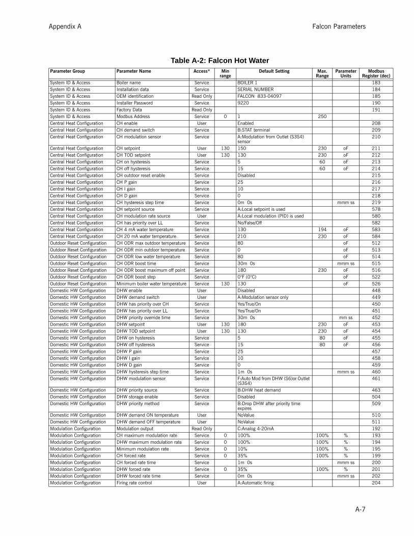
Appendix A Falcon Parameters
odbus ter (dec)183184185190191
208209210
211212213214215216217218219578580582583584512513514515516522526448449450451452453454455456457458459460461
463504509
510511192193194195199200201202204
Table A-2: Falcon Hot WaterParameter Group Parameter Name Access* Min
rangeDefault Setting Max.
RangeParameter
UnitsM
RegisSystem ID & Access Boiler name Service BOILER 1System ID & Access Installation data Service SERIAL NUMBERSystem ID & Access OEM identification Read Only FALCON 833-04097System ID & Access Installer Password Service 9220System ID & Access Factory Data Read OnlySystem ID & Access Modbus Address Service 0 1 250Central Heat Configuration CH enable User EnabledCentral Heat Configuration CH demand switch Service B:STAT terminalCentral Heat Configuration CH modulation sensor Service A:Modulation from Outlet (S3S4)
sensorCentral Heat Configuration CH setpoint User 130 150 230 oFCentral Heat Configuration CH TOD setpoint User 130 130 230 oFCentral Heat Configuration CH on hysteresis Service 5 60 oFCentral Heat Configuration CH off hysteresis Service 15 60 oFCentral Heat Configuration CH outdoor reset enable Service DisabledCentral Heat Configuration CH P gain Service 25Central Heat Configuration CH I gain Service 10Central Heat Configuration CH D gain Service 0Central Heat Configuration CH hysteresis step time Service 0m 0s mmm ssCentral Heat Configuration CH setpoint source Service A:Local setpoint is usedCentral Heat Configuration CH modulation rate source User A:Local modulation (PID) is usedCentral Heat Configuration CH has priority over LL Service No/False/OffCentral Heat Configuration CH 4 mA water temperature Service 130 194 oFCentral Heat Configuration CH 20 mA water temperature Service 210 230 oFOutdoor Reset Configuration CH ODR max outdoor temperature Service 80 oFOutdoor Reset Configuration CH ODR min outdoor temperature Service 0 oFOutdoor Reset Configuration CH ODR low water temperature Service 80 oFOutdoor Reset Configuration CH ODR boost time Service 30m 0s mmm ssOutdoor Reset Configuration CH ODR boost maximum off point Service 180 230 oFOutdoor Reset Configuration CH ODR boost step Service 0°F (0°C) oFOutdoor Reset Configuration Minimum boiler water temperature Service 130 130 oFDomestic HW Configuration DHW enable User DisabledDomestic HW Configuration DHW demand switch User A:Modulation sensor onlyDomestic HW Configuration DHW has priority over CH Service Yes/True/OnDomestic HW Configuration DHW has priority over LL Service Yes/True/OnDomestic HW Configuration DHW priority override time Service 30m 0s mm ssDomestic HW Configuration DHW setpoint User 130 180 230 oFDomestic HW Configuration DHW TOD setpoint User 130 130 230 oFDomestic HW Configuration DHW on hysteresis Service 5 80 oFDomestic HW Configuration DHW off hysteresis Service 15 80 oFDomestic HW Configuration DHW P gain Service 25Domestic HW Configuration DHW I gain Service 10Domestic HW Configuration DHW D gain Service 0Domestic HW Configuration DHW hysteresis step time Service 1m 0s mmm ssDomestic HW Configuration DHW modulation sensor Service F:Auto Mod from DHW (S6)or Outlet
(S3S4)Domestic HW Configuration DHW priority source Service B:DHW heat demandDomestic HW Configuration DHW storage enable Service DisabledDomestic HW Configuration DHW priority method Service B:Drop DHW after priority time
expiresDomestic HW Configuration DHW demand ON temperature User NoValueDomestic HW Configuration DHW demand OFF temperature User NoValueModulation Configuration Modulation output Read Only C:Analog 4-20mAModulation Configuration CH maximum modulation rate Service 0 100% 100% % Modulation Configuration DHW maximum modulation rate Service 0 100% 100% % Modulation Configuration Minimum modulation rate Service 0 10% 100% % Modulation Configuration CH forced rate Service 0 35% 100% % Modulation Configuration CH forced rate time Service 1m 0s mmm ssModulation Configuration DHW forced rate Service 0 35% 100% % Modulation Configuration DHW forced rate time Service 0m 0s mmm ssModulation Configuration Firing rate control User A:Automatic firing
A-7

Falcon Parameters Appendix A
205477478479480534
543667272273274275
276277278279
280281282283284285287288289290291292293294295296297298299300301302303752753754755756757758759760128130132134136138140146464465474
odbus ter (dec)
Modulation Configuration Manual firing rate User 0 30% 100% % Modulation Configuration CH slow start enable Service EnabledModulation Configuration DHW slow start enable Service DisabledModulation Configuration Slow start ramp Service 0 5% 100% % per minModulation Configuration Slow start degrees Service 20 oFModulation Configuration Rate assigned to 0V/4mA (Min mod
> 80%)User 100% 0 to 100%
Modulation Configuration Analog input hysteresis Service .2 mAModulation Configuration Analog rate tracking User A:Analog rate tracking disabledPump Configuration CH pump output Service A:No pump assignmentPump Configuration CH pump control Service A:Automatic pump controlPump Configuration CH pump overrun time Service 5m 0s mmm ssPump Configuration CH pump frost protection overrun
timeService 60m 0s mmm ss
Pump Configuration DHW pump output Service A:No pump assignmentPump Configuration DHW pump control Service A:Automatic pump controlPump Configuration DHW pump overrun time Service 1m 0s mmm ssPump Configuration DHW pump frost protection overrun
timeService 60m 0s mmm ss
Pump Configuration DHW pump start delay Service 1m 0s mmm ssPump Configuration Boiler pump output Service C:Pump assigned to terminal BPump Configuration Boiler pump control Service A:Automatic pump controlPump Configuration Boiler pump overrun time Service 5m 0s mmm ssPump Configuration Auxiliary 1 pump output Service D:Pump assigned to terminal CPump Configuration Auxiliary 1 pump control Service A:Automatic pump controlPump Configuration System pump output Service A:No pump assignmentPump Configuration System pump control Service A:Automatic pump controlPump Configuration System pump overrun time Service 15m 0s mmm ssPump Configuration Pump exercise interval Service 0 DaysPump Configuration Pump exercise time Service 0m 0s mmm ssPump Configuration CH pump start delay Service 0m 10s mmm ssPump Configuration Boiler pump start delay Service 0m 10s mmm ssPump Configuration System pump start delay Service 0m 0s mmm ssPump Configuration Auxiliary 1 pump start delay Service 0m 20s mmm ssPump Configuration CH pump options 1 Service 0x0324Pump Configuration CH pump options 2 Service 0xC048Pump Configuration DHW pump options 1 Service 0x0048Pump Configuration DHW pump options 2 Service 0x4190Pump Configuration Boiler pump options 1 Service 0x0002Pump Configuration Boiler pump options 2 Service 0x4009Pump Configuration System pump options 1 Service 0x0360Pump Configuration System pump options 2 Service 0x8009Pump Configuration Auxiliary 1 pump overrun time Service 5m 30s mmm ssPump Configuration Auxiliary 1 pump options 1 Service 0x0262Pump Configuration Auxiliary 1 pump options 2 Service 0x4019Pump Configuration Auxiliary 2 pump output Service B:Pump assigned to terminal APump Configuration Auxiliary 2 pump control Service A:Automatic pump controlPump Configuration Auxiliary 2 pump start delay Service 0m 0s mmm ssPump Configuration Auxiliary 2 pump overrun time Service 3m 0s mmm ssPump Configuration Auxiliary 2 pump options 1 Service 0x0003Pump Configuration Auxiliary 2 pump options 2 Service 0x4000Statistics Configuration Burner cycle count Read Only 0 CyclesStatistics Configuration Burner run time Read Only 0 HoursStatistics Configuration CH pump cycle count Service 0 CyclesStatistics Configuration DHW pump cycle count Service 0 CyclesStatistics Configuration System pump cycle count Service 0 CyclesStatistics Configuration Boiler pump cycle count Service 0 CyclesStatistics Configuration Auxiliary 1 pump cycle count Service 0 CyclesStatistics Configuration Auxiliary 2 pump cycle count Service 0 CyclesHigh Limits Outlet high limit setpoint Service 32 240 250 oFHigh Limits Outlet high limit response Read Only A:LockoutHigh Limits DHW high limit enable Service A:No high limit
Table A-2: Falcon Hot Water (Continued)Parameter Group Parameter Name Access* Min
rangeDefault Setting Max.
RangeParameter
UnitsM
Regis
A-8

Appendix A Falcon Parameters
475476484466467468469470471472473485486487488481482483492493496497499500502502502502502502503
528529530532533304306307309319320322332333335345346348358359361371372374384385387397398
odbus ter (dec)
High Limits DHW high limit setpoint Service 32 NoValue 250 oFHigh Limits DHW high limit response Service B:Recycle && holdHigh Limits Outlet high limit enable Read Only B:Dual sensor safety high limitStack Limit Stack limit enable Service A:No stack high limitStack Limit Stack limit setpoint Service 250 266 oFStack Limit Stack limit response Service A:LockoutStack Limit Stack limit delay Service 5m 0s mmm ssDelta-T Limits Delta-T inlet/outlet enable Service D:Enable both Delta-T and inversionDelta-T Limits Delta-T inlet/outlet degrees Service 50 oFDelta-T Limits Delta-T response Service C:Recycle && delay with retry limitDelta-T Limits Delta-T delay Service 5m 0s mmm ssDelta-T Limits Delta-T retry limit Service 3 100Delta-T Limits Delta-T rate limit enable Service EnabledDelta-T Limits Delta-T inverse limit time Service 5m 0s 30m 0s mmm ssDelta-T Limits Delta-T inverse limit response Service C:Recycle && delay with retry limitT-rise Limit Outlet T-rise enable Service DisabledT-rise Limit T-rise degrees Service 10 oFT-rise Limit T-rise delay Service 3m 0s mmm ssT-rise Limit T-rise response Service C:Recycle && delay with retry limitT-rise Limit T-rise retry limit Service 10Anticondensation Configuration CH anticondensation enable Service DisabledAnticondensation Configuration CH anticondensation setpoint Service 130 230 oFAnticondensation Configuration DHW anticondensation enable Service EnabledAnticondensation Configuration DHW anticondensation setpoint Service 130 230 oFAnticondensation Configuration Anticondensation > Forced rate User Yes/True/OnAnticondensation Configuration Anticondensation > Slow start User Yes/True/OnAnticondensation Configuration Anticondensation > Outlet limit User No/False/OffAnticondensation Configuration Anticondensation > Stack limit User No/False/OffAnticondensation Configuration Anticondensation priority ServiceAnticondensation Configuration Anticondensation > Delta-T User No/False/OffAnticondensation Configuration Frost protect anticondensation
enableService Disabled
Frost Protection Configuration CH frost protection enable Service DisabledFrost Protection Configuration DHW frost protection enable Service DisabledFrost Protection Configuration Outdoor frost protection setpoint Service 32 oFFrost Protection Configuration LL frost protection enable Service DisabledFrost Protection Configuration LL frost protection rate Service 0 20% 100% %Annunciation Configuration Annunciation enable Read Only EnabledAnnunciation Configuration Annunciator 1 location OEM E:Other annunciationAnnunciation Configuration Annunciator1 short name OEM A1Annunciation Configuration Annunciator 1 long name OEM AIR SWITCHAnnunciation Configuration Annunciator 2 location Service A:No annunciation for this terminalAnnunciation Configuration Annunciator2 short name Service A2Annunciation Configuration Annunciator 2 long name Service AUX LOW WATERAnnunciation Configuration Annunciator 3 location OEM D:Interlock circuitAnnunciation Configuration Annunciator3 short name OEM A3Annunciation Configuration Annunciator 3 long name OEM LOW WATERAnnunciation Configuration Annunciator 4 location OEM D:Interlock circuitAnnunciation Configuration Annunciator4 short name OEM A4Annunciation Configuration Annunciator 4 long name OEM HIGH AIR PRESSUREAnnunciation Configuration Annunciator 5 location OEM D:Interlock circuitAnnunciation Configuration Annunciator5 short name OEM A5Annunciation Configuration Annunciator 5 long name OEM HIGH GAS PRESSUREAnnunciation Configuration Annunciator 6 location OEM D:Interlock circuitAnnunciation Configuration Annunciator6 short name OEM A6Annunciation Configuration Annunciator 6 long name OEM LOW GAS PRESSUREAnnunciation Configuration Annunciator 7 location Service A:No annunciation for this terminalAnnunciation Configuration Annunciator7 short name Service HFSAnnunciation Configuration Annunciator 7 long name Service HIGH FIRE SWITCHAnnunciation Configuration Annunciator 8 location Service A:No annunciation for this terminalAnnunciation Configuration Annunciator8 short name Service LFS
Table A-2: Falcon Hot Water (Continued)Parameter Group Parameter Name Access* Min
rangeDefault Setting Max.
RangeParameter
UnitsM
Regis
A-9

Falcon Parameters Appendix A
400410412422424434436229230238246
248249253196198207231235236197224226227232233234250
239240241243178179181203225228254255608609610611612613615
617626627628630631639264545546547549
odbus ter (dec)
Annunciation Configuration Annunciator 8 long name Service LOW FIRE SWITCHAnnunciation Configuration PII short name OEM PIIAnnunciation Configuration PII long name OEM Pre-Ignition ILKAnnunciation Configuration LCI short name OEM LCIAnnunciation Configuration LCI long name OEM Limit Circuit InputAnnunciation Configuration ILK short name OEM ILKAnnunciation Configuration ILK long name OEM Lockout InterlocksInterlocks Purge rate proving Service B:Prove via HFS terminalInterlocks Lightoff rate proving Service B:Prove via LFS terminalInterlocks Interlock open response Read Only A:LockoutInterlocks Interrupted air switch enable OEM { xBCx } C:Enable IAS during purge &&
ignitionInterlocks LCI enable Read Only EnabledInterlocks PII enable OEM EnabledInterlocks ILK bounce detection enable Service EnabledSafetey Timing Prepurge rate Service 60 65% 100% % Safetey Timing Postpurge rate Service 40 50% % Safetey Timing Standby rate Service 0 35% 100% % Safetey Timing Prepurge time Service 0m 30s 0m 30s mmm ssSafetey Timing Run stabilization time Service 0m 10s mmm ssSafetey Timing Postpurge time Service 0m 15s 0m 15s mmm ssIgnition Configuration Lightoff rate Service 0 25% 50% % Ignition Configuration Ignition source Read Only B:External ignitionIgnition Configuration Igniter on during Read Only B:On in first half of PFEPIgnition Configuration Pilot type Read Only A:Interrupted (off during Run)Ignition Configuration Preignition time Service 0m 0s mmm ssIgnition Configuration PFEP Read Only C:10 secondsIgnition Configuration MFEP OEM B:5 secondsIgnition Configuration Flame threshold OEM .5 .8 5 10ths (V or
uA)Flame Failure Ignite failure response Service A:LockoutFlame Failure Ignite failure retries Service D:Retry 1 timeFlame Failure Ignite failure delay Service 0m 30s 60m 0s mmm ssFlame Failure Run flame failure response Read Only A:LockoutSystem Configuration Temperature units Service A:FahrenheitSystem Configuration Antishort cycle time Service 0m 0s mmm ssSystem Configuration Power up with lockout OEM EnabledSystem Configuration Burner switch User No/False/OffSystem Configuration BLR HSI function Read Only A:Blower motorSystem Configuration Flame sensor type Service D:UV power tube, ignore ignitor UVSystem Configuration Forced recycle interval time Service 0h 0m minSystem Configuration Fan speed error response Service A:LockoutSystem Configuration Inlet connector type Read Only D:10K single non-safetySystem Configuration S2 connector type OEM H:4_20_MASystem Configuration Outlet connector type Read Only C:10K dual safetySystem Configuration S5 connector type Service D:10K single non-safetySystem Configuration DHW connector type Service D:10K single non-safetySystem Configuration Stack connector type Service A:connector unconfiguredSystem Configuration Outdoor temperature correction
offsetUser 0
System Configuration Low fire cutoff time User 0m 30s mmm ssSystem Configuration Outdoor temperature source Service A:unconfiguredSystem Configuration Warm weather shutdown enable Service A:Warm weather shutdown disabledSystem Configuration Warm weather shutdown setpoint Service 100 oFSystem Configuration Line frequency Service C:auto detect 48 through 63 HzSystem Configuration Safety configuration options OEM 0x0001System Configuration Burner off inhibit time User NoValue mmm ssFan Configuratiosn Fan min duty cycle Service 10 0-100%Lead Lag Configuration Lead lag master enable Service A:no Lead Lag masterLead Lag Configuration Lead lag CH setpoint User 130 150 230Lead Lag Configuration Lead lag CH TOD setpoint User 130 130 230Lead Lag Configuration Lead lag on hysteresis Service 5 oF
Table A-2: Falcon Hot Water (Continued)Parameter Group Parameter Name Access* Min
rangeDefault Setting Max.
RangeParameter
UnitsM
Regis
A-10

Appendix A Falcon Parameters
550551552553554555556557559560
561
569
572574575704705706714
716718719
722723725
727728
731733734735736737544564567568570
517
518
519520521
524527
548
odbus ter (dec)
*Access Levels:Read Only = parameter not configurableOEM = manufacturer onlyService = password required (default password is 9220)User = no password required
Lead Lag Configuration Lead lag off hysteresis Service 15 oFLead Lag Configuration Lead lag hysteresis step time Service 0m 0s mmm ssLead Lag Configuration Lead lag P gain Service 20Lead Lag Configuration Lead lag I gain Service 15Lead Lag Configuration Lead lag D gain Service 0Lead Lag Configuration Lead lag operation switch User No/False/OffLead Lag Configuration Lead lag CH demand switch Service B:STAT terminalLead Lag Configuration Lead lag CH setpoint source Service A:Local setpoint is usedLead Lag Configuration Lead lag modulation backup sensor Service B:Use Outlet sensor from lead boilerLead Lag Configuration Lead lag CH 4 mA water
temperatureService 80 oF
Lead Lag Configuration Lead lag CH 20 mA water temperature
Service 180 oF
Lead Lag Configuration Lead Lag Modbus port Service C:Use MB2 port for Lead Lag messaging
Lead Lag Configuration Base load common Service 45% 0 to 100%Lead Lag Configuration Lead selection method Service A:rotate in sequence orderLead Lag Configuration Lag selection method Service A:rotate in sequence orderLead Lag Configuration Lead lag DHW demand switch User A:DHW loop is disabledLead Lag Configuration Lead lag DHW setpoint User 180 oFLead Lag Configuration Lead lag DHW has priority over CH User Yes/True/OnLead Lag Configuration Lead lag add stage method 1 Service C:Use firing rate threshold to add
stageLead Lag Configuration Lead lag add stage detection time 1 Service 1m 0s 3m 0s mmm ssLead Lag Configuration Lead lag add stage error threshold Service 5 oFLead Lag Configuration Lead lag add stage rate offset Service 0% -100% to
100%Lead Lag Configuration Lead lag add stage interstage delay Service 3m 0s 10m 0s mmm ssLead Lag Configuration Lead lag drop stage method 1 Service C:Use firing rate to drop stageLead Lag Configuration Lead lag drop stage detection time
1Service 1m 0s 3m 0s mmm ss
Lead Lag Configuration Lead lag drop stage error threshold Service 10 oFLead Lag Configuration Lead lag drop stage rate offset Service -3% -100% to
100%Lead Lag Configuration Lead lag drop stage interstage delay Service 3m 0s 10m 0s mmm ssLead Lag Configuration Lead rotation time Service 120h 0m minLead Lag Configuration Force lead rotation time Service 168h 0m minLead Lag Configuration Lead lag DHW TOD setpoint User 130 170 oFLead Lag Configuration Boiler off options Service A:boiler off options disabledLead Lag Configuration All boilers off threshold Service 210 oFLead Lag Configuration Lead lag slave enable Service A:DisabledLead Lag Configuration Slave mode Service B:Equalize runtimeLead Lag Configuration Fan during off cycle rate Service 0% % Lead Lag Configuration Slave sequence order Service 0 1 to 8Lead Lag Configuration Lead lag slave demand to firing
delayService 1m 0s 3m 0s mmm ss
Lead Lag Configuration LL CH ODR max outdoor temperature
Service 80 140 oF
Lead Lag Configuration LL CH ODR min outdoor temperature
Service 0 140 oF
Lead Lag Configuration LL CH ODR low water temperature Service 80 230 oFLead Lag Configuration LL CH ODR boost time Service 0m 0s mmm ssLead Lag Configuration LL CH ODR boost maximum off
pointService 180 oF
Lead Lag Configuration LL CH ODR boost step Service 0 oFLead Lag Configuration LL CH ODR minimum water
temperatureService 80 230 oF
Lead Lag Configuration Lead lag CH outdoor reset enable Service Disabled
Table A-2: Falcon Hot Water (Continued)Parameter Group Parameter Name Access* Min
rangeDefault Setting Max.
RangeParameter
UnitsM
Regis
A-11

Falcon Parameters Appendix A
A-12

APPENDIX B
Control Parameters - LMV / RWF50


APPENDIX C
Variable Speed Drive Parameters


APPENDIX D
Dungs Gas Valve(M5M 2000 - 3000)


1 … 18
M/C
D •
Karl
Dun
gs In
c. •
MBC
-SE.
... •
Editio
n 20
14.1
1 • P
/N 2
64 5
41
UL Listed / Recognized Component: File No. MH16727 to UL 429
CSACertifiedFileNo.157406to ANSIZ21.21/CSA6.5withC/Imarking ANSI Z21.18 / CSA 6.3
FM7400Approved
CommonwealthofMassachusettsApprovedProductApprovalcodeG1-1107-35
MBC-SE 1000/2500/4000GasMultiBloc®
Combined servo pressure regulator and safety shut-off valvesInstallation Instructions
TableofContents
USA CDN
TableofContents . . . . . . . . . . . . . . . . . . . . . . . . Page1Approvals . . . . . . . . . . . . . . . . . . . . . . . . . . . . . . . Page1Attention . . . . . . . . . . . . . . . . . . . . . . . . . . . . . . . . Page1Specification . . . . . . . . . . . . . . . . . . . . . . . . . . . . Page2Mounting. . . . . . . . . . . . . . . . . . . . . . . . . . . . . . . . Page3PaintingValve . . . . . . . . . . . . . . . . . . . . . . . . . . . Page4ProtectionfromRadiantHeat . . . . . . . . . . . . . . Page4ElectricalDINConnectorRatings . . . . . . . . . . . Page5ElectricalDINConnectorassembly&wiring . Page6MBCOverview&ImpulseLines . . . . . . . . . . . . Page7OutletPressureAdjustment . . . . . . . . . . . . . . . Page9Changingcoil . . . . . . . . . . . . . . . . . . . . . . . . . . . . Page10InternalFilter . . . . . . . . . . . . . . . . . . . . . . . . . . . . Page12TestPorts . . . . . . . . . . . . . . . . . . . . . . . . . . . . . . . Page13ValveLeakageDecayTest . . . . . . . . . . . . . . . . . Page14
Approvals
1, 2, 3 ... = Action • =Instruction
Explanation of symbols
On completion of work on thesafetyvalve,performaleakageandfunctiontest.
Please read the instructionbe-foreinstallingoroperating.Keeptheinstructioninasafeplace.Youfindtheinstructionalsoatwww.dungs.comIftheseinstructionsarenotheeded, the resultmaybepersonalinjuryordamagetoproperty.Anyadjustmentandapplication-specificadjustmentvaluesmustbemadeinaccordancewiththeappliance-/boilermanufacturersinstructions.
Attention
Check the ratings in thespeci-ficationstomakesurethattheyaresuitableforyourapplication.
This product is intended forinstallations covered by, butnot limited to, the followingfuel gas codesandstandards:NFPA 54, IFGC (InternationalFuelGasCode),orCSAB149.1(for Canada) or the followingequipmentcodesandstandards:CSD-1,UL795,NFPA37,ANSIZ83.4/CSA 3.7, ANSI Z83.18, ANSI Z21.13/CSA 4.9, or CSA B149.3 (forCanada).
[V] [A] [Hz] [VA]
Safetyfirst
O.K.IFGC
CSAULANSI
NFPA
Theinstallationandmaintenanceof this product must be doneunderthesupervisionofanex-periencedandtrainedspecialist.Neverperformworkifgaspres-sure or power is applied, or inthepresenceofanopenflame.
ValveLeakageBubbleTest(Altern.method) . Page15FlowCurve . . . . . . . . . . . . . . . . . . . . . . . . . . . . . . Page16PressureDropforotherGases . . . . . . . . . . . . . Page17Accessories&Replacement . . . . . . . . . . . . . . . Page18

2 … 18
M/C
D •
Karl
Dun
gs In
c. •
MBC
-SE.
... •
Editio
n 20
14.1
1 • P
/N 2
64 5
41
Specification
Safety Valve Max. OperatingPressureMOP = 5 PSI (360 mbar)
Regulator Operating PressureRatingsS22/S82: pin = 6 - 147 in. W.C.S302: pin = 14 - 147 in. W.C.S02: pin = 4 - 41 in. W.C.N: pin = 4 - 41 in. W.C.
RegulatorOutletPressureRangesS22: pout = 1.6 - 8 in. W.C.S82: pout = 2 - 32 in. W.C.S302: pout = 12- 122 in. W.C.S02: pout = 0 ± 0.8 in. W.C.N: pout = 0 ± 0.8 in. W.C.
AmbientTemperature(CSA)-40 °F ... +140 °F(-40 °C … +60 °C)AmbientTemperature(UL)+5 °F ... +140 °F(-15 °C … +60 °C)
GasesDry, natural gas, propane, butane; other noncorrosive gases. A “dry” gas has a dew point lower than +15 °F and its relative humidity is less than 60 %. MaterialsincontactwithGasHousing: Aluminium, Steel, free of nonferrous metals. Sealings on valve seats: NBR-based rubber.
ElectricalRatings110 - 120 VAC / 50 - 60 Hz; 24 VAC / 50 - 60 Hz; 12 VDC, 24 VDCOperatingtime100 % duty cycleCycleRateMaximum 60 cycles/hr (30 s on/off)
Filterinstalled in the housing upstream V150 micron
Classification of Valve V1 and V2Safety Shutoff Valve: UL 429, ANSI Z21.21 • CSA 6.5 C/I ValvesClosingTime(Valve1&Valve2)< 1 sOpening Time (Valve1&Valve2) < 1 s
MBC- Two normally closed safety shutoff valves with integrated servo regulator in one housing. Fast opening, fast closing.
[PSI]
[V] [A] [Hz] [VA]
Gas
°F
0-40
+150
ElectricalConnectionDIN-connector with 1/2” NPT conduit connection for UL Versions.Order separately for CSA VersionsPowerConsumptionwithallcoilsenergizedsee table below
NEMA
EnclosureRatingNEMA Type 12 / IP54
VentLimitingDeviceandVentLineConnectionThe MBC has an internal, factory installed vent limiter re ANSI Z21.18/CSA 6.3. Venting required unless otherwise accepted by the authority having jurisdiction.
PowerConsumptionTableValveBodySize Ratedvoltage InrushPmax.
[VA]fort=3sInrushcurrentpeak(A)
HoldingPmax.[VA]Operation
Recommendedpowerofsupplytransformer(VA)
MBC 100012 VDC
140 20.1 16 DC batteryMBC 2500 160 20.1 20 DC batteryMBC 4000 – – – –MBC 1000
24 VDC130 13.4 16 DC battery
MBC 2500 160 13.4 20 DC batteryMBC 4000 200 2.8 30 DC batteryMBC 1000
24 VAC*120 14.7 20 250
MBC 2500 160 13.9 20 300MBC 4000 – – – –MBC 1000
120 VAC*120 3.1 16 250
MBC 2500 180 3.0 20 300MBC 4000 250 2.4 25 300*Power supply should compensate for the inrush current, and wire gauge should be considered. In order to absorb voltage spikes during inrush, an electrolytic capacitor (4700 µF) between MBC and transformer is recommended.

3 … 18
M/C
D •
Karl
Dun
gs In
c. •
MBC
-SE.
... •
Editio
n 20
14.1
1 • P
/N 2
64 5
41
Donotovertightenthescrews.Followthemaximumtorquevaluesnextpage.
If theflowisnot in thesamedirectionof thearrows,thevalveswillnotoperateproperly.
Setup1. Examine the MBC valve for shipping damage.2. The main gas supply must be shutoff before starting the
installation.3. The inside of the MBC valve, the flanges, and piping must
be clean and free of dirt. Remove all dirt and debris before installing the MBC valve. Failure to remove dirt / debris could result in valve damage or improper performance.
RecommendedProceduretoMounttheFlanges1. Unpack the MBC valve and remove the socket cap head
screws from white plastic cover. For MBC 1000: use 5 mm hex wrench for M6 screws For MBC 2500/4000: use 6 mm hex wrench for M8 screws 2. Verify the o-rings and the grooves are clean and in good
condition.3. Install flanges and torque to specification.4. Clean the mounting surface of the flanges. 5. Mount the flanges to the MBC valve. 6. Tighten the screws in a crisscross pattern. See table for
recommended torque!
InstallationpositionSEVersionsendinginS22/S82/S302
2016 12 8
4
pBr
2016
1284pBr
2016
1284 p Br
2016128
4
pBr
2016 12 8
4
pBr
2016
128
4pB
r
2016
128
4 p Br
2016128
4
pBr
InstallationpositionSEVersionsendinginS02
Mounting

4 … 18
M/C
D •
Karl
Dun
gs In
c. •
MBC
-SE.
... •
Editio
n 20
14.1
1 • P
/N 2
64 5
41
ProtectionfromRadiantHeat• Radiant heat must be considered as a heat source that
could result in an ambient temperature higher than the rat-ing of this valve.
• Provide proper shielding to protect against radiant heat.
PaintingValve
18
19
Chrome S
teel �
Mad
e in G
erman
y
[Ib-in]
RecommendedPipingProcedure• Use new, properly reamed and threaded pipe free of chips.• Apply good quality pipe sealant, putting a moderate
amount on the male threads only. If pipe sealant lodges on the valve seat, it will prevent proper operation. If using LP gas, use pipe sealant rated for use with LP gas.
• OncompletionofworkontheMBCvalve,performaleakagetest.(See“ValveLeakageTest”)
• Do not thread pipe too far. Valve distortion and/or mal-function may result from excess pipe in the valve body.
• Apply counter pressure only a parallel jaw wrench only to the flats on the flange when connecting to pipe.
• Do not overtighten the pipe. Follow the maximum torque values listed below.
• It is not recommended that this valve be painted. Painting covers date codes and other labels that identify this valve.
• If the valve needs to be painted, a paint free of volitile organic componants (VOC’s) must be used. VOC’s can damage valve o-rings, resulting in external gas leakage over time.
• During the painting process, use measures that will allow the valve’s date code and other labeling information to be legible after the paint is dry.
• Painting the valve may damage valve o-rings, resulting in external gas leakage over time.
RecommendedTorqueforPiping
1/2” 3/4” 1” 11/4” 11/2” 2” NPTpipe
375 560 750 875 940 1190 [Ib-in]
RecommendedTorqueSystemAccessories
M6 M8 ScrewSize
62 lb-in 134 lb-in [Ib-in]
18
19
Chrome S
teel �
Mad
e in G
erman
y
[Ib-in]

5…18
M/C
D •
Karl
Dun
gs In
c. •
MBC
-SE.
... •
Editio
n 20
14.1
1 • P
/N 2
64 5
41
DINConnectorscrewterminalconnections
-L2(AC)Neutral-(DC)
Ground
L1(AC)Hot+(DC)Valve1
L1(AC)Hot+(DC)Valve2
AmbientTemperatureRating: -40°F to +175°FElectricalRatings:120VAC, 24VAC 50/60 Hz, 12 VDC or 24VDC.MaximumAmperageRating:6.0 Amps @ 120VAC.EnclosureRating:Type 12ElectricalWiringConnection: Screw terminals.RequiredWireSpecifications:Type: Stranded, insulated Appliance Wiring Material (AWM) “Hook-Up” wire.Approvals: UL Recognized Single Conductor, Thermoplastic Insulated Wire, Type AWM. Temperature Rating: At least 75°C (170°F). Voltage Rating: 300 Volts maximum / Single phase. Wire Size: AWG #18 minimum ONLY. No more the AWG #14.
Ratingsforconduitandconduitfittings:Temperature: At least 75°C (170°F) Voltage: 300 Volts minimumApprovals: UL Listed conduit and conduit fittingsSize: 1/2” Conduit and 1/2” Conduit Fitting.Selectoneconduittypeanditssuitableconduitfittingfromthefollowingtable.
Liquid-tight, metallic fitting,Type FLEX/MC (Flexible/Metal Clad)
Standard thickness, steel or aluminum, Flexible Metal Clad Conduit
Liquid-tight, Flexible Non-Metallic Conduit (LFNC-B) Type B
Liquid-tight, Flexible Metallic Conduit
Metallic fitting,Type “squeeze”, “set screw”, or “screw-in”
Liquid-tight, non-metallic fitting, Type NM (non-metallic) conduit fitting
1/2”ConduitTypeandSuitable1/2”ConduitFitting
ONLY with
ONLY with
ONLY with
InitialSetup:1. Verify that all power to all wires at the terminals in the nearest
conduit body (panel) are disconnected before proceeding.2. At least 4 wires (1 Safety Ground, 2 Hot and 1 Neutral) are
needed for wiring. NOTE: One neutral wire can be used to power both valves.
IMPORTANT: DO NOT make any terminal connections at the nearest conduit body until all terminals in the valve con-nector are properly wired and the valve connector is properly assembled to the 1/2” flexible conduit.
NOTE: Flexible conduit more than 3ft. long must be properly supported and secured, as specified in NFPA 70, Article 350 and 351.
ElectricalDINConnectorRatings

6 … 18
M/C
D •
Karl
Dun
gs In
c. •
MBC
-SE.
... •
Editio
n 20
14.1
1 • P
/N 2
64 5
41
7. Tighten the screws on the metal strain relief.Themaximumtorqueforeachmetalstrainreliefscrewis4.4in-lb(0.5Nm).8. Assemble the appropriate 1/2” flexible conduit and its suit-
able conduit fitting as specified in the table on page 3.9. Route the “pig-tailed” wires from the valve connector
through the 1/2” conduit and to the nearest conduit body (panel), and then screw the valve connector to the 1/2” conduit fitting (see below for proper torque).
NOTE: It may be necessary to pull the wires at the nearest conduit body to reduce any potential wire slack in the raceway as the valve connector is screwed to the 1/2” conduit fitting.
10. Assemble the cover and mounting screw to the valve con-nector, and mount the valve connector to the valve coil as shown below.
11. Tighten the mounting screw. 12. Follow NEC (NFPA 70) requirements for proper termination
at the nearest conduit body.
Failuretofollowtheexactinstructionsbelowmayresultinavalveconnectornotfittingtovalve.
STEPS1. After selecting the proper number of wires, push the mount-
ing screw completely out from the valve connector and disassemble the remaining 4 parts as shown below:
2. Starting from the 1/2” NPT end of the housing, push the wires under the metal strain relief and through the housing (see FIG. A below). The GREEN (ground) wire should be placed into the far left groove when viewed as shown in FIG. B. The “Neutral (-) ” should be placed into the groove next to the GREEN (ground).
3. Continue to push the wires through the housing until there is at least an extra 3”- 6”available for connecting the wires to the terminals on the T-Block (see FIG. A above).
4. Strip no more than 1/4” of insulation from each wire.5. Wiring to the correct terminal is critical. The terminals are
labeled next to the terminal screws. Terminate each wire to its proper terminal on the T-block. See FIG. C to determine the proper terminals for the valve. NOTE: One neutral is used to power both valves.
Mounting ScrewTerminal Block(T-Block)
Cover
Themaximumtorqueatthe1/2”NPTconduithousingconnectionis60in-lb(6.75Nm).
Fig. A
Strip the end of each lead 1/4” maximum
push wires
pull 3”-6” of extra wire
Neutral -
Metal Strain Relief
Ground
Fig. B
Fig. D
Ground
Fig. E
Themaximumtorqueformountingscrewis8.8in-lb(1.0Nm).
Housing
Themaximumtorquefortheterminalscrewsis4.4in-lb(0.5Nm).6. Pull the wires so that the T-Block is completely pulled into
the housing. As the T-Block gets pulled into the housing, the T-Block and the wires must be properly guided into the housing by:
A) Ensuring that the ground (the flat pin of the plug) fits to the front of the housing as shown in FIG. D below,
AND B) Ensuring that the wires lay side-by-side beneath the metal
strain relief as shown in Fig. E below, ANDC) Organizing the wires so that they terminate on the same
side of the connector under which they were routed. The wires must NOT crisscross inside the housing to the op-posite side from which they are terminated. Fig. C illustrates how the wires terminate on the same side under which they were routed.
Terminal#2Hot (+) for valve #1
Terminal#3Hot (+) for valve #2
Ground
Terminal#1Neutral (-)
Fig. C
Hot +
ElectricalDINConnectorassembly&wiring

7 … 18
M/C
D •
Karl
Dun
gs In
c. •
MBC
-SE.
... •
Editio
n 20
14.1
1 • P
/N 2
64 5
41
Impulselinesmustbeorderedseparately
1
5
6
13
9
113
24
7
812
10
MBCOverview&ImpulseLines
1 Electrical connection for valves (DIN EN 175 301-803) black 2 Input flange 3 Pressure connection G 1/8 upstream of filter 4 Filter5 Label / Seriel number 6 Cover 7 Test point connection G 1/8 upstream of V1, possible on both sides 8 Test point connection G 1/8 downstream of V2, optional 9 Regulator Outlet Pressure Adjustment10 Vent connection / Vent limiter G 1/811 G 1/8 pressure connection Burner pressure pBr
12 Output flange13 Test point connection G 1/8 downstream of V1 and upstream V2, possible on both sides.

8 … 18
M/C
D •
Karl
Dun
gs In
c. •
MBC
-SE.
... •
Editio
n 20
14.1
1 • P
/N 2
64 5
41
MBC...SERecommendedInstallationofImpulselineswhenused(optional)
M
12
2016 12 8
4
pBr
min. 5 x Diameter
Diameter
ExternalImpulseline(option)AssemblyInstructions
Impulse line pBR must cor-respond to ≥ DN 4 (1/8”), PN
1 and they must be made of steel.
OthermaterialsforImpulselinesareonlypermittedafteracertifica-tionwiththeburner/boiler.
CloseinternalImpulselinewithgrubscrew.SeeFig.1
Route Impulse line so that no condensate can flow back to
the MBC...SE. See Fig. 2
1 2 1 2
MBC1000/2500Fig. 1
MBC4000
Secure Impulse line to prevent them from being ripped out and
deformed.KeepImpulselineshort!
Test Impulse line for external leakage. Use leakage spray
only if necessary.Testpressure:pmax.=40”W.C.
Close this port with grub screw if using external feedback
Close this port with grub screw if using external feedback
12
external feedback
breathing port

9 … 18
M/C
D •
Karl
Dun
gs In
c. •
MBC
-SE.
... •
Editio
n 20
14.1
1 • P
/N 2
64 5
41
ProtectiveslideAfter setting the required pressure setpoint:1. Close protective slide.2. Secure protective slide closed
position with a screw
1
MetricAllenkeyno.2.5
2
OutletPressureAdjustment
MetricAllenkeyno.2.5
3
MBC...SES22/82/302• Open protective slide located at the bottom of the valve.• See Fig. 1 & 2 for adjustments.
1. Make adjustments while the valve is energized and flame established.2. Using a 2.5 mm Metric Allen key, adjust the outlet pressure to the gas
regulator for the application. Turning the adjustment towards lower numbers decreases the outlet pressure. Turning the adjustment towards higher numbers increases the outlet pressure.
3. Verify that the outlet pressure and the products of combustion are within the operating range as specified by the original equipment manufacturer.
MBC...SES02&MBCN1. Open protective slide located at the bottom of the valve.2. See Fig. 1 & 2 for low fire adjustments.3. See Fig. 3 for high fire adjustments
NOTE: There will be a slight delay between the adjustments and the re-sponse of the flue gas measuring equipment.
NOTE: Making high fire adjustments can affect the low fire setting, and vice versa. Therefore, modulate the equipment up and down at least three times to double check the low fire and high fire emissions after making adjustments.
HighFiresettingusingShutterflange1. With valve energized and flame established, drive the appliance to high fire.2. Use a slotted screwdriver to adjust the gas/air ratio concentration for the
application. Turn the adjustment towards the – symbol to decrease gas flow. Turn the adjustment towards the + symbol to increase gas flow.3. Verify that products of combustion are within the operating range as
specified by the original equipment manufacturer.
LowFiresettingusingMBCregulator1. With valve energized and flame established, adjust the fan speed to the
minimum firing rate for the appliance.• It is important to only adjust the low fire gas / air ratio concentration for
the application while the appliance is operating at its minimum firing rate.• The minimum negative signal to zero governor must be at least -0.2 ”WC.
This can be measured at the test port downstream both safety shutoff valves with the blower on and running at the minimum firing rate RPM.
• NOTE: Both safety shutoff valves must be closed to read this signal pressure. This will be a negative pressure/vacuum signal.
2. Using a 2.5mm Metric Allen key, adjust the offset pressure to the gas / air ratio concentration for the application.
Turn the adjustment towards the – symbol to decrease the outlet pres-sure.
Turn the adjustment towards the + symbol to increase the outlet pressure. 3. Verify that products of combustion are within the operating range as
specified by the original equipment manufacturer.Readallinstructionsinthismanualbeforeinstalling.Per-formstepsintheordergiven.Haveinstalledandserviced/
inspected by a qualified service technician, at least annually.Failuretocomplycouldresult inseverepersonalinjury,deathorsubstantialpropertydamage.
AcalibratedfluegasanalyzermustbeutilizedtoproperlyadjustappliancesfeaturingDUNGSMBCcontrols.Failureto
properlyapplyafluegasanalyzercanresultincarbonmonoxideemissionscausingseverepersonalinjury,deathorsubstantialpropertydamage.
Failuretofollowallinstructionscanresultincarbonmon-oxideemissionscausingseverepersonalinjuryordeath.
Shutterflange
MBCregulator

10…18
M/C
D •
Karl
Dun
gs In
c. •
MBC
-SE.
... •
Editio
n 20
14.1
1 • P
/N 2
64 5
41
1
A
A
2
B
3 4
5
B
ChangingcoilMBC-1000/25001.Shutoffgassupplyanddisconnect power sup-ply!
2. Undo locking screw A, Fig. 13. Remove cover B, Fig. 24. Exchange solenoid, Fig. 3
Always observe solenoidNo.andvoltage!
5. Replace cover B, tighten by hand, Fig. 4
6. Screw in locking screw A to stop, Fig. 5

11 … 18
M/C
D •
Karl
Dun
gs In
c. •
MBC
-SE.
... •
Editio
n 20
14.1
1 • P
/N 2
64 5
41
B
4. Carefully lift off solenoid cover, Fig. 3.
5. Disconnect grounding and PCB connectors, Fig. 4.
6. Replace solenoid, Fig. 5
MBC-40001.Shutoffgassupplyanddisconnectpowersup-ply!
2. Undo locking screw A, Fig. 1.3. Remove cover B, Fig. 2.
1 2
3 4 5
6
B
A
B
A
7
Note: CoilV1wireconnectionblack/white
CoilV2wireconnectionred/blue
Replacementsolenoidiscompleteassembled.
7. Make electrical connec-tions. Assemble in reverse order.
8. Reattach cover B, tighten securely by hand only, Fig. 6.
9. Tighten lock screw A as far as the stop, Fig. 7.

12 … 18
M/C
D •
Karl
Dun
gs In
c. •
MBC
-SE.
... •
Editio
n 20
14.1
1 • P
/N 2
64 5
41
Inspect the filter at least once a year.Changethefilter, if ∆p be-tween pressure connections 1 and 2 > 4” W.C.
12
3
Spacerequirementsforfittingfilter:
MBC-1000-...: 6“MBC-2500-...: 7“MBC-4000-...: 9“
ForproductiondatecodesMay2007ornewer,thisfeatureispresent.
1
InternalFilterChangethefilter, if ∆p be-tween pressure connections 1 and 2 is twice as high com-pared to the last inspection.
1. Interrupt gas supply: close upstream ball valve
2. Remove screws 1-23. Change filter insert 3
4. Screw in screws 1-2 without using any force and fasten 22 in. lbs (2.5 Nm).
5. Perform leakage and func-tion test, pmax = 5 PSI

13 … 18
M/C
D •
Karl
Dun
gs In
c. •
MBC
-SE.
... •
Editio
n 20
14.1
1 • P
/N 2
64 5
41
TestPortsThe G 1/8 ISO 228 taps are available on both sides up-stream V1, between V1 and
Pressuretaps
MBC-1000/2500…
1,2,3,4,5G 1/8 Screw plug
2016128
4
pBr
2016 12 8
4
pBr
4
5
4
3
1
23
1
2
6, 7
3 4
4
5
3
1
2
2
3 4
4
5
3
1
2
2
P1L1
MpN
P2L2
6, 7
MBC-4000…
6Air pressure signal7 Combustion chamber pressureMBC-SE...
V2, downstream V2, and on both flanges. The G 1/8 tes nipple (P/N 219-008) can be
screwed in any of these pres-sure tap ports.

14 … 18
M/C
D •
Karl
Dun
gs In
c. •
MBC
-SE.
... •
Editio
n 20
14.1
1 • P
/N 2
64 5
41
This test method is an alternative to bubble tightness testing in case there is no manually operated shutoff valve installed downstream of the MBC.Preparation for leak testing:1) Ensure that the appliance is not in operation.2) This test requires: • A manometer capable of reading +/- 0.1”WC. • A stopwatch. • A hose barb connection that fits to manometer and
the valve test port.3) The manual shutoff valve upstream of the MBC must re-
main open during this test. In addition, the manual shutoff valve downstream of the MBC, if installed, must remain open during this test.
4) The test also requires the ability to open and close safety valve #1 and safety valve #2 independently using the volt-age as indicated on the coil.
5) Externally leak test the valve and all piping connected to the valve including the upstream manual shutoff valve and the manometer connection. DUNGS recommends using an all purpose liquid leak detector solution (Snoop™ or a non-aggressive soapy water solution). The presence of bubbles indicates a leak.
6) The DIN connector of the MBC Valve has three connections that provide power to the coil along with a ground connec-tion. Pin numbers indicated on DIN connector.
Pin # 2 = Line voltage Valve #1Pin # 3 = Line voltage Valve #2Pin # 1 = Neutral Valve #1 & 2
= Ground
Procedure for Testing Valve #11) Connect a manometer to Port 2 on the side of the MBC2) Determine the test time according the valve size, as indi-
cated on table 1.3) Energize valve 2 by powering terminal 3 with the voltage
indicated on the coil housing. Ensure that terminal #1 is connected to Neutral and that the safety ground is also connected to ground.
4) Mark the pressure reading on the manometer, which should be zero.
5) With a stopwatch ready, de-energize valve 2 and imme-diately start the timer. Watch the manometer for pressure change.
6) As soon as the test time expires, determine the amount of pressure rise. Reference table 2 for action to be taken.
Procedure for Testing Valve #21) Connect a manometer to Port 2 on the side of the MBC 2) Determine the test time according the valve size, as indi-
cated on table 1.3) Energize valve 1 by powering terminal 2 with the voltage
indicated on the coil housing. Ensure that terminal #1 is connected to Neutral and that the safety ground is also connected to ground.
4) Mark the pressure reading on the manometer, which should be equal to the inlet pressure to the valve.
5) With a stopwatch ready, de-energize valve 1 and imme-diately start the timer. Watch the manometer for pressure change.
6) As soon as the test time expires, determine the amount of pressure change. Reference table 2 for action to be taken.
After completing the above tests:1) Remove the manometer, and close Port 2.2) Use soapy water to leak test all connections including Port
2 to ensure that there are no leaks.
ValveLeakageDecayTest
Leakage rates according to UL 429 and ANSI Z21.21Testtime(s) Allowableleakage(cc/hr) Maximumpressuredrop
(in.W.C.)MBC 1000 4.0 235.0 2.0MBC 2500 5.0 305.0 2.0MBC 4000 6.0 470.0 2.0
Analysis of test resultsPressuredrop/rise(in.W.C.)
Acceptable Testresults
2.0 or less Yes PassMore than 2.0 No Fail - Immediately replace valve
-L2(AC)Neutral-(DC)
Ground
L1(AC)Hot+(DC)Valve1
L1(AC)Hot+(DC)Valve2

15…18
M/C
D •
Karl
Dun
gs In
c. •
MBC
-SE.
... •
Editio
n 20
14.1
1 • P
/N 2
64 5
41
ValveLeakageBubbleTest(Altern.method)This leak test procedure tests the external sealing and valve seat sealing capabilities of the MBC automatic safety shutoff valve. Only qualified personnel should perform this test.
It is required that this test be done on the initial system startup, and then repeated at least annually. Possibly more often de-pending on the application, environmental parameters, and the requirements of the authority having jurisdiction.
SetupThis test requires the following:A) Test nipples installed in the downstream pressure tap port
of each automatic safety shutoff valve to make the required 1/4” hose connection in step 4.
B) A transparent glass of water filled at least 1 inch from the bottom.
C) A proper leak test tube. An aluminum or copper 1/4” rigid tube with a 45˚ cut at the end that is then connected to a 1/4” flexible hose of some convenient length provides for a more accurate leakage measurement.
However, a 45˚ cut at the end of the 1/4” flexible hose will suffice, but it will not likely be as accurate as the rigid tube.
D) For detecting external leakages, an all purpose liquid leak detector solution or a soapy water solution is required.
LeakTestProcedureUse the illustration below as a reference. 1. With the upstream ball valve open, the downstream ball
valve closed and both valves energized, apply an all pur-pose liquid leak detector solution to the “External Leak-age Test Areas” indicated in the illustration below, to any accessories mounted to the safety valve, and to all gas piping and gas components downstream the equipment isolation valve, and the inlet and outlet gas piping of the automatic safety shutoff valve. The presence of bubbles
indicates a leak, which needs to be rectified before pro-ceeding.
2. Then, de-energize the burner system and verify that both automatic safety shutoff valves are closed.
3. Close the upstream and downstream manual ball valve. 4. Using a screwdriver, slowly open the V1 test nipple (port 2)
by turning it counter clockwise to depressurize the volume between the two valves, and connect the 1/4” flexible hose to the test nipple.
5. Slowly open the upstream manual ball valve, and then pro-vide for some time to allow potential leakage to charge the test chamber before measuring the valve seat leakage.
6. Immerse the 1/4 in. tube vertically 1/2 in. (12.7 mm) below the water surface. If bubbles emerge from the 1/4” tube and after the leakage rate has stabilized, count the number of bubbles appearing during a 10 second period. (See chart below for allowable leakage rates.)
7. Repeat the same procedure for valve V2 (port 3). (Energize terminal 2 on the DIN connector to open valve 1)
Aftercompletingtheabovetestsproceedasfollows: 8. Verify that the downstream manual ball valve is closed,
and both automatic safety shutoff valves are de-ener-gized.
9. Remove the flexible hose, and close all test nipples. 10. With the upstream manual ball valve open, energize both
automatic safety shutoff valves.11. Use soapy water to leak test all test nipples to ensure that
there are no leaks.12. If no leakage is detected, de-energize all automatic safety
shutoff valves, and open the downstream manual ball valve.
Type AllowableValveSeat #ofBubblesin10sLeakage*upto7PSIinlet Air NaturalGas LP
MBC 1000 235 cc/hr 5 6 4MBC 2500 305 cc/hr 7 8 6MBC 4000 470 cc/hr 10 11 9*Based on air and test conditions per UL 429 Section 29. (Air or inert gas at a pressure of 1/4 psig and also at a pressure of one and one-half times maximum operating pressure differential, but not less than 1/2 psig. This test shall be applied with the valve installed in its intended position.)Volume of bubble defined in Table 2 of FCI 70-2-1998.
Ifleakagevaluesareexceeded,replacevalveimmediately.
2016 12 8
4
pBr
Leak Test Here
2016 12 8
4
pBr
1/2”1”
1/4 “ Rigid Tube
1/4 “ Flex Hose G 1/8” Test Nipple# D219 008
Port 2 Leak Test for V1Port 3 Leak Test for V2

16 … 18
M/C
D •
Karl
Dun
gs In
c. •
MBC
-SE.
... •
Editio
n 20
14.1
1 • P
/N 2
64 5
41
FlowCurve
10 20 30 40 60 80 100 200 400 600 2,000 10,0004,000 7,000800 1,000
NPT
1/2
NPT
3/4
NPT
1 &
1 1
/4
Basedon60°F14.65psia,dry
MBC-1000-...
MBC-2500-...Curvesforequipmentselection(inregulatedstate)withmicrofilter
100 200 400 600 2,000 10,0004,000 7,000800 1,000
NPT
1N
PT 1
1/4
NPT
1 1
/2 &
2
20,000 40,000 100,000
Basedon60°F14.65psia,dry

17 … 18
M/C
D •
Karl
Dun
gs In
c. •
MBC
-SE.
... •
Editio
n 20
14.1
1 • P
/N 2
64 5
41
PressureDropforotherGasesTo determine the pressure drop when using a gas other than natural gas, use the flow formula below and f value located in the table below to determine the “corrected” flow rate in CFH through the valve for the other gas used. For example,
when using propane, divide the volume (CFH) of propane required for the application by the calculated value f (f = 0.66 for propane). Use this “corrected” flow rate and the flow curve on the next page to determine pressure drop for propane.
Density of Natural gas
Density of gas usedf=
Typeofgas Density[kg/m3] s.g. f
Natural gas 0.81 0.65 1.00Butane 2.39 1.95 0.58Propane 1.86 1.50 0.66Air 1.24 1.00 0.80
Determiningequivalentflowthroughvalvesusinganothergas
Vgas used = V Natural gas x f° °
MBC-4000-...Curvesforequipmentselection(inregulatedstate)withmicrofilter
100 200 400 600 2,000 10,0004,000 7,000800 1,000
NPT
2
20,000 40,000 100,000
Basedon60°F14.65psia,dry

18 … 18
M/C
D •
Karl
Dun
gs In
c. •
MBC
-SE.
... •
Editio
n 20
14.1
1 • P
/N 2
64 5
41
Accessories&Replacement1/4”NPTport1orport2adapter(reducedport) 225-0471/2”NPTport2pilotgasadapter(reducedport) 225-043G1/8”Testnipplewithgasket 219-008GasketforG1/8”Testnipple 171-260Port3pressureswitchmountingadapter 214-975DUNGSDINConnector 210-310 Ordered separately on CSA / FM versionsBurkertDINConnectorforULListing 253-731 included as standard on UL and UR versionsConduitAdapter 240-671 for use with 210-310
KarlDungsGmbH&Co.KGP.O.Box1229D-73602Schorndorf,GermanyPhone+49(0)7181-804-0Fax +49(0)[email protected]://www.dungs.com
KarlDungsInc.3890PheasantRidgeDriveNESuite150Blaine,MN55449,U.S.A.Phone763582-1700Fax [email protected]://www.dungs.com/usa/
ValveDescription Flange NPTP/N
O-ringandboltkitP/N
MBC1000
1/2” 222-371 224-0933/4” 222-368 224-0931” 221-999 224-0931 1/4” 231-718 224-0931 1/2” 244-021 224-093
MBC2500/4000
1” 222-369 224-0941 1/4” 222-370 224-0941 1/2” 222-003 224-0942” 221-997 224-094
*Includes two o-rings and two sets of bolts (one set of four bolts for each flange).
**Includes four bolts and one o-ring.
ReplacementCoilsValve 120VAC 24VAC 12VDC 24VDCMBC 1000 250-371 250-680 251-136 252-191MBC 2500 250-175 250-681 251-226 252-192MBC 4000 252-613 not available not available 252-193Printed wiring board is not replaceable
ShutterFlangesPartdescription MBC1000 MBC2500/
MBC40001 " NPT (flange only) 253-205 256-7891" NPT Flange set (with o-ring and 4 screws) 255-132 256-7911.5" NPT (flange only) NA 253-2061.5" NPT Flange set (with o-ring and 4 screws) NA 255-133

APPENDIX E
Siemens Gas Valve(M5M 3500 - 6000)


VG Series
Technical InstructionsDocument No. 155-512P25
VG…August 11, 2005
VGG… and VGD… Gas Valves for use with SKP… Electro-hydraulic Actuators
GA
S00
39R
1
VGG… VGD20… VGD40…
Only when assembled to SKP… Series actuators
Description The normally closed VG… Series of modular single and double-body gas valves combined with SKP… Series electro-hydraulic actuators provide safety shut-off, gas pressure regulation and air/gas ratio control for commercial and industrial gas burners.
Table 1. Legend.
Model Numbers Body Style Connection
VGG… Single NPT Threaded
VGD… Double NPT Threaded or ANSI Flanged
Features All Models
• UL listed, FM approved, CSA certified, IRI approvable, ISO 9001 and 14000 certified. European, Australian and Japanese approved versions available.
• Stainless steel mesh inlet filter protects the valve seat(s) as well as downstream components.
• 1/4-inch NPT pressure taps on the inlet and outlet. (See Table 2 for details).
• Dual stem guides ensure precise disc alignment and tight shut-off.
VGG… Models • Contoured valve disc provides smooth release of gas and stable regulating control.
• 3/4-inch NPT port for pilot or vent line connection on 2-1/2 and 3-inch VGG…valves.
Siemens Building Technologies, Inc.

Technical Instructions VG Series Gas Valves for Use with Electro-hydraulic Document Number 155-512P25 Actuators SKP… August 11, 2005
VGD20… Models
• Compact VGD20… double-valve bodies consist of two safety shut-off valves in series. The first (inlet) valve has a flat valve disc applicable for safety shut-off function only. The second (outlet) valve has a contoured valve disc for use with pressure regulating actuators (SKP2…, SKP5…, SKP7…).
• A one-inch NPT vent connection between the valves.
• Each VGD20… double-valve requires two threaded mounting flanges (AGAxxU). Each flange includes the necessary installation hardware (bolts, nuts and O-ring). Each mounting flange has a 1/4-inch NPT pressure tap. The flanges can be pre-mounted onto the pipe, and then bolted onto the VGD20… gas valve body. This feature eliminates the use of pipe unions and permits the gas valve assembly to be easily removed from a gas train.
• The overall dimensions of both the 1-1/2-inch and 2-inch AGAxxU flanges are identical. This permits a 1-1/2-inch flange to be mounted on a 2-inch valve body or vice versa.
NOTE: VGD20… valves and AGAxxU threaded flanges must be ordered as separate items (See Table 2).
VGD40… Models
• Compact VGD40… double-valve bodies consist of two safety shut-off valves in series.
• Each individual safety shut-off valve has double seats to achieve high flow.
• Patented seat construction with individual closing spring for each seat to assure reliable shut-off and high close-off pressure rating.
• Full port vent line connection plates are available. NOTE: VGD40… valves and AGA… vent connection plates must be ordered as separate
items (See Table 2).
Application All VG… valves can be combined with any SKP… Series actuator. The actuator can be mounted while the valve is installed and under pressure.
SKP… regulating actuators are applicable for both low and high supply gas pressure applications, eliminating excessive regulator inventories. Maximum pressure ratings vary with valve size (See Table 2).
All VG… valves perform these functions in combination with each of the following actuators:
SKP15… Safety shut-off SKP25… Safety shut-off and constant pressure regulation or zero governor. SKP55… Safety shut-off, pressure regulation and differential pressure air/gas ratio control. SKP75… Safety shut-off, pressure regulation and adjustable air/gas ratio control.
Since more than one function can be performed by a single valve, fewer components and fittings are required to assemble a gas train - significantly reducing both the size and weight of the gas train. In addition, smaller diameter gas valves can be used. For details on valve sizing see the Gas Flow Charts (Figures 4 and 5).
CAUTION: Do not oversize valves equipped with a regulating SKP… actuator. Oversizing may limit turndown and could cause oscillations.
Ordering Information
Gas valves and actuators are ordered separately. For additional SKP… actuator information, see the following Technical Instructions:
SKP15… 155-751P25 SKP25… 155-752P25 SKP55… 155-753P25 SKP75… 155-754P25
Page 2 Siemens Building Technologies, Inc.

VG Series Gas Valves for Use with Electro-hydraulic Technical Instructions Actuators SKP… Document Number 155-512P25 August 11, 2005
Accessories Manual adjusting throttle attachment AGA61 permits VG… series valves to be used as adjustable limiting orifice valves. Once adjusted, the AGA61 has a provision to be sealed from tampering (See Table 3). Adapter plate AGA60 permits VG… series valves to be used for modulating flow control when fitted with an SQX… series modulating actuator (See Table 3).
NOTE: The VG… /SQX… valve/actuator combination is designed strictly for modulating flow control and does not provide safety shut-off function.
Table 2. Product Numbers. Number of
Test Points, 1/4" NPT
Product Number
Size
Maximum Operating Pressure
psi
Close-off
Pressure psi
Capacity CFH
Natural Gas at
∆P=1" W.C. Inlet Outlet
3/4" NPT Port
Valve Body
Material
VGG10.154U 1/2" NPT 20 75 327/242◆ 2 2 — Aluminum VGG10.204U 3/4" NPT 20 75 614/442◆ 2 2 — Aluminum VGG10.254U 1" NPT 20 75 914/686◆ 2 2 — Aluminum VGG10.404U 1-1/2" NPT 20 75 2,047/1,643◆ 2 2 — Aluminum VGG10.504U 2" NPT 15 75 3,511 2 2 — Aluminum VGG10.654U 2-1/2" NPT 10 25 5,085 1 1 2-inlet Cast Iron VGG10.804U 3" NPT 10 25 6,158 1 1 2-inlet Cast Iron
*VGD20.403U 1-1/2" 20 30 1,890 — Aluminum *VGD20.503U 2" 15 30 2,300
Two 1/4-inch and one 1-inch port between valves
— Aluminum
*AGA41U Single 1-1/2" connecting flange with 1/4-inch port for VGD 20.403U
*AGA51U Single 2" connecting flange with 1/4-inch port for VGD 20.503U
Two (2) needed per valve. Order separately
VGD40.065U 2-1/2" NPT 10 75 3,880 1 1 Aluminum VGD40.080U 3" NPT 10 75 5,370 1 1 Aluminum VGD40.100U 4" Flanged 10 30 9,680 1 1 Aluminum VGD40.150U 6" Flanged 10 30 17,490 1 1
Two 1/4-inch NPT
ports between the
valves
Aluminum
* VGD20… double valves require 2 AGAxxU threaded flanges for installation. ◆ VGG… valves, 1/2- through 1-1/2 inch have reduced flow when used with AGA66 (NEMA 4 kit). Capacities shown are without/with NEMA 4 kit (See Figure 4a).
Siemens Building Technologies, Inc. Page 3

Technical Instructions VG Series Gas Valves for Use with Electro-hydraulic Document Number 155-512P25 Actuators SKP… August 11, 2005
Table 3. Accessories.
Part Number Description Notes
AGA40.6580U Vent connection plate with 1-1/4" NPT vent connection and 1/4" NPT test port AGA40.0100U Vent connection plate with 2" NPT vent connection and 1/4" NPT test port AGA40.0150U Vent connection plate with 2-1/2" NPT vent connection and 1/4" NPT test port
Order separately. For use with VGD40… only.
AGA60 Adapter for use with SQX… actuators AGA61 Manual operation kit, allows VG… valves to be used as adjustable limiting orifice valve. AGA66 Sealing gasket to provide NEMA 3, NEMA 3R, and NEMA 4 protection.
Specifications Approvals
Agency approvals/standards UL/429, FM/7400, CSA/AINSI Z21.21/CGA 6.5 Commercial/Industrial IRI approvable Agency marks apply only for VGxxx.xxxU series gas valve bodies assembled with SKPxx.xxxU actuators.
Operating Environment
Maximum operating pressure See Table 2 Maximum back pressure (differential) 2.5 psi (150 mbar) Close-off pressure See Table 2 Permissible gases Natural gas, propane, butane, air, and other non-
corrosive gases. Permissible gas temperature 5°F to 140°F (-15°C to 60°C) Permissible operating temperature 5°F to 140°F (-15°C to 60°C) Mounting Any position except upside down
Physical Characteristics
Body materials See Table 2 Weight See Tables 4 through 7
Connections Pipe connections NPT or ANSI Class 150 flange (See Table 2) Pressure and vent taps See Table 2
Operation All VG… gas valves are normally closed, two-way valves. The valves have a standard, integral, stainless steel mesh filter (0.8 mm) in the inlet to protect the downstream components against contamination. VGG… series gas valves have a contoured valve disc for stable regulating control and smooth release of gas (see Figure 1). VGD20… double valves consist of two valves in series. The first (inlet) valve has a flat valve disc suitable for the safety shut-off function only. The second (outlet) valve has a contoured valve disc for stable regulating control and smooth release of gas (see Figure 2). VGD40… double valves consist of two valves in series. Each valve has a double seat to achieve high flow (see Figure 3). All valves have 1/4-inch NPT ports for pressure test connection. The 2-1/2-inch and 3-inch VGG… valves have an additional 3/4-inch NPT port for a pilot connection. The VGD20… valves have a 1-inch NPT port for a vent line connection. The VGD40… valves can be equipped with a full size vent connection plate.
See Table 1 for details on ports and vent connection plates.
Page 4 Siemens Building Technologies, Inc.

VG Series Gas Valves for Use with Electro-hydraulic Technical Instructions Actuators SKP… Document Number 155-512P25 August 11, 2005 Operation, Continued
Figure 1. VGG… Models. Figure 2. VGD20… Models.
GA
S00
34R
1
Figure 3. VGD40… Models.
Siemens Building Technologies, Inc. Page 5

Technical Instructions VG Series Gas Valves for Use with Electro-hydraulic Document Number 155-512P25 Actuators SKP… August 11, 2005 Gas Flow Charts
2100 3 4 5 7 1000 2 3 4 5 7 32 4 5 7 10000010000
2 3 4 5 7 10000
2 3 4 5 7 10000
2 3 4 5 7 10007 100
7 100 2 3 4 5 7 1000
2 3 4 5 7 1000100
32 4 5 7 100000
32 4 5 7 100000
32
32
2
2
324 5 7 100000
32 4 5 7 32 4 5 71000
2 3 4 5 7 10000
3 4 5 7 10 32 4 5 7 100
10.70.50.40.3
0.2
2
345710
20
30405070100
200
3004005007001,000
2,000
1,000700500400300
200
10070504030
20
107543
2
10.70.50.4
GAS0058R1
cf/h 1 Natural Gas
cf/h 2 Propane Gas
cf/h 3 Butane Gas
cf/h 4 Air
m3/h 4 Air
0.64
1.52
2.00
1.00
1.00
Sp. Gr.
" W.C. mbarVGG
1/2"
1" 1-1/2"
2"3/4"
2-1/2"
3"
Figure 4. Sizing Single Valves Without NEMA 4 Kit.
NOTE: Pressure drop is for one valve when using an SKPx5…actuator without a NEMA 4 kit (AGA66).
CAUTION: Do not oversize valves equipped with regulating actuators SKP2…, SKP5… or SKP7… Oversizing may limit turndown and could cause oscillations.
Page 6 Siemens Building Technologies, Inc.

VG Series Gas Valves for Use with Electro-hydraulic Technical Instructions Actuators SKP… Document Number 155-512P25 August 11, 2005
Gas Flow Charts, Continued
2100 3 4 5 7 1000 2 3 4 5 7 32 4 5 7 10000010000
2 3 4 5 7 10000
2 3 4 5 7 10000
2 3 4 5 7 10007 100
7 100 2 3 4 5 7 1000
2 3 4 5 7 1000100
32 4 5 7 100000
32 4 5 7 100000
32
32
2
2
324 5 7 100000
32 4 5 7 32 4 5 71000
2 3 4 5 7 10000
3 4 5 7 10 32 4 5 7 100
10.70.50.40.3
0.2
2
345710
20
30405070100
200
3004005007001,000
2,000
1,000700500400300
200
10070504030
20
107543
2
10.70.50.4
GAS0059R1
cf/h 1 Natural Gas
cf/h 2 Propane Gas
cf/h 3 Butane Gas
cf/h 4 Air
m3/h 4 Air
0.64
1.52
2.00
1.00
1.00
Sp. Gr.
" W.C. mbarVGG
1/2"
1" 1-1/2"
2"3/4"
2-1/2"
3"
Figure 4a. Sizing Single Valves With a NEMA 4 Kit.
NOTE: Pressure drop is for one valve when using an SKPx5…actuator and a NEMA 4 kit (AGA66).
CAUTION: Do not oversize valves equipped with regulating actuators SKP2…, SKP5… or SKP7… Oversizing may limit turndown and could cause oscillations.
Siemens Building Technologies, Inc. Page 7

Technical Instructions VG Series Gas Valves for Use with Electro-hydraulic Document Number 155-512P25 Actuators SKP… August 11, 2005 Gas Flow Charts, Continued
2100 3 4 5 7 1000 2 3 4 5 7 32 4 5 7 10000010000
2 3 4 5 7 10000
2 3 4 5 7 10000
2 3 4 5 7 10007 100
7 100 2 3 4 5 7 1000
2 3 4 5 7 1000100
32 4 5 7 100000
32 4 5 7 100000
32
32
2
2
324 5 7 100000
32 4 5 7 32 4 5 71000
2 3 4 5 7 10000
3 4 5 7 10 32 4 5 7 100
10.70.50.40.3
0.2
2
345710
20
30405070100
200
3004005007001,000
2,000
1,000700500400300
200
10070504030
20
107543
2
10.70.50.4
GAS0040R1
PRESSU
RE D
ROP ∆ p
cf/h 1 Natural Gas
cf/h 2 Propane Gas
cf/h 3 Butane Gas
cf/h 4 Air
m3/h 4 Air
0.64
1.52
2.00
1.00
1.00
Sp. Gr.
" W.C. mbar
1-1/2"
2" 2-1/2"
3" 4" 6"
Figure 5. Sizing Double Valves.
NOTE: Pressure drop is total drop across both valves when using an SKPx5… actuator, with or without an AGA66.
CAUTION: Do not oversize valves equipped with regulating actuators SKP2…, SKP5… or SKP7… Oversizing may limit turndown and could cause oscillations.
Page 8 Siemens Building Technologies, Inc.

VG Series Gas Valves for Use with Electro-hydraulic Technical Instructions Actuators SKP… Document Number 155-512P25 August 11, 2005
Dimensions
A
B
1-1/4(30) L
FK
D�
1/4" NPT4.33 (110) 4.33 (110)
GAS0060R1
Table 4. VGG… Models. Valve Model
Nominal Size
D Inches
A Inches (mm)
B Inches(mm)
E Inches(mm)
F Inches(mm)
K Inches (mm)
L Inches (mm)
WeightPounds
(kg) VGG… 1/2 1-1/4
(32) 3-1/8 (79)
1-1/8 (28)
1-7/32 (31)
2-3/16 (55)
4-3/8 (110)
1.65 (0.75)
3/4 1-1/4 (32)
3-1/8 (79)
1-1/8 (28)
1-7/32 (31)
2-3/16 (55)
4-3/8 (110)
1.65 (0.75)
1 1-1/4 (32)
3-18 (79)
1-1/8 (28)
1-7/32 (31)
2-3/16 (55)
4-3/8 (110)
1.5 (0.7)
1-1/2 1-5/8 (41)
4 (102)
1-5/16 (34)
1-5/16 (34)
3 (75)
5-15/16 (150)
3.3 (1.5)
2 2 (50)
4-1/4 (107)
1-5/16 (34)
1-5/16) (34)
3-3/8 (85)
6-3/4 (170)
4.0 (1.8)
2-1/2 3-5/8 (92)
6-7/16 (163)
— 2-7/16 (62)
5-11/16 (145)
11-7/16 (290)
32.5 (14.8)
3 3-15/16 (100)
6-7/16 (163)
— 2-7/16 (62)
6-1/16 (155)
12-3/16 (310)
34 (15.5)
Siemens Building Technologies, Inc. Page 9

Technical Instructions VG Series Gas Valves for Use with Electro-hydraulic Document Number 155-512P25 Actuators SKP… August 11, 2005
Dimensions, Continued
Table 5. VGD20… Models. Valve Model Nominal Size D
Inches L
Inches (mm) Weight
Pounds (kg) 1-1/2 12-3/16
(310) 7
(3.2) VGD20…
2 12-5/8 (320)
6 (3.15)
Page 10 Siemens Building Technologies, Inc.

VG Series Gas Valves for Use with Electro-hydraulic Technical Instructions Actuators SKP… Document Number 155-512P25 August 11, 2005
Dimensions, Continued Dimensions in Inches (mm)
a) Standard connection plate
GA
S00
35R
1
GA
S00
36R
1
Table 6. VGD40… Models. Valve Model A B C D E F G H I J K * L M S T VGD40.065U 12.09
(307) 7.00 (203)
3.25 (83)
4.63 (118)
2.09 (53)
1.46 (37)
4.02 (102)
6.14 (156)
1.57 (40)
2-1/2"NPT
SW 100
__ __ 1.77 (45)
2.44 (62)
VGD40.080U 12.87 (327)
8.94 (227)
3.64 (93)
5.18 (132)
1.85 (47)
0.79 (20)
4.21 (107)
6.30 (160)
1.85 (47)
3" NPT
SW 120
__ __ 2.34 (60)
2.83 (72)
VGD40.100U 13.78 (350)
10.50 (267)
4.33 (110)
5.70 (145)
1.93 (49)
1.95 (50)
5.16 (131)
7.56 (192)
0.63 (16)
__ __ d=7.50 (191)
d=0.75 (19)
2.34 (60)
4.55 (116)
VGD40.150U 18.90 (480)
13.29 (338)
5.71 (145)
7.40 (188)
2.09 (53)
2.30 (59)
6.61 (168)
10.31 (262)
0.63 (16)
__ __ d=9.49 (241)
d=0.91 (23)
3.54 (90)
5.61 (143)
* Spanner width in millimeters
Siemens Building Technologies, Inc. Page 11

Technical Instructions VG Series Gas Valves for Use with Electro-hydraulic Document Number 155-512P25 Actuators SKP… August 11, 2005
Information in this publication is based on current specifications. The company reserves the right to make changes in specifications and models as design improvements are introduced. Other product or company names mentioned herein may be the trademarks of their respective owners. © 2005 Siemens Building Technologies, Inc.
Dimensions, Continued
Option a) Connection plate with 1/4" NPT plugged pressure test port b) Vent connection plate with vent line connection and 1/4" NPT plugged pressure test port
Note: Plates a) and b) are interchangeableG
AS
0037
R1
Table 7. VGD40… Dimensions in Inches (Millimeters). Valve Model N O P Q R Weight
Pounds (kg) VGD40.065U 7.13
(181) 4.06 (103)
5.34 (136)
3.02 (77)
1.46 (37)
16 (7)
VGD40.080U 7.28 (185)
4.13 (105)
5.49 (140)
3.17 (81)
0.79 (20)
19 (3)
VGD40.100U 8.54 (217)
4.76 (121)
6.26 (159)
3.94 (100)
1.95 (50)
29 (13)
VGD40.150U 11.30 (287)
6.14 (156)
7.80 (198)
5.47 (139)
2.30 (59)
53 (24)
Table 8. Vent Connection Plate Dimensions.
VG
D40
.065
U
VG
D40
.080
U
VG
D40
.100
U
VG
D40
.150
U Thread Vent
Connection Size
AGA40.6580U X X 1-1/4" NPT
AGA40.0100U X 2" NPT
GA
S00
38R
1
AGA40.0150U X 2-1/2" NPT
Page 12

Siemens Building Technologies, Inc.
SKP Series
Technical Instructions Document No. 155-754
SKP75…U.. July 1, 2005
SKP75…U.. Air/Gas Ratio Controlling Gas Valve Actuator with Safety Shutoff Function
Only when assembled to Series VG… Gas valves
Description SKP75… pressure regulating electro-hydraulic actuators are used in combination with VG… series gas valve bodies to provide shut-off and air/gas ratio control for industrial and commercial burner applications.
The SKP75… controls the burner manifold gas pressure as a function of the combustion air pressure without the need for an additional constant gas pressure regulator.
Since three functions: safety shut-off, constant pressure regulation, and air/gas ratio control can be performed by a single valve, fewer gas train components and fittings are required. This significantly reduces both the size and weight of the gas train. In addition, smaller diameter gas valves can be used.
The compact SKP75… actuator opens slowly and closes immediately when power is interrupted. The modular design allows the SKP75… to be used in combination with all VG… series gas valves bodies from 1/2-inch to 6-inch in size. The actuator is easily mounted on the square flange of any VG… valve with four pre-mounted screws. A visible position indicator on the front of the actuator displays the entire stroke of the valve. A light indicates when the actuator is powered.
Features • UL listed, FM approved, CGA and AGA certified, IRI approvable, ISO 9001 certified; European, Australian and Japanese approved versions available.
• Safety shut-off function, pressure regulating function and air/gas ratio control in one compact unit.
• Proof of Closure with Over Travel (POC) versions are available.
• Optional NEMA 4 protection.
• Simplifies commissioning and reduces start-up time.
• Maintains air/gas ratio when the airflow is disrupted.
• Automatic compensation for combustion chamber back pressure fluctuations.
• No mechanical wear or play that causes drifting.

Technical Instructions SKP75…U.. Air/Gas Ratio Controlling Actuators Document No. 155-754 July 1, 2005
Page 2 Siemens Building Technologies, Inc.
Features, Continued • Compensation for air temperature fluctuations.
• Visual position indication.
• "Power on" indication light
• Quick connect wiring terminals
• Optional adjustable auxiliary switch available.
• Excellent tracking characteristic.
• Modular design with 360o actuator rotation for easy field wiring and installation.
• Low, 13.5 VA power consumption.
Application SKP75… series actuators can be combined with 1/2-inch to 6-inch VG… series gas valve bodies. VG… series gas valves must be ordered separately (See VG…U...Technical Instructions, P/N 155-512P25).
If the combustion air pressure exceeds the permissible value of 12” or 20” w.c. (See Specifications), the pressure must be reduced by means of a pressure reducing T-fitting (See Figure 4, AGA78).
Product Numbers Table 1.
Product Number1 Operating Voltage Proof of Closure Switch 2
Auxiliary Switch 2
Type of Switch
SKP75.011U1 x – SPDT SKP75.012U1 x x SPDT SPDT SKP75.013U1
110 to 120 Vac
– – SKP75.012U2 x x SPDT SPDT SKP75.013U2
220 to 240 Vac – –
1. European, CE certified models are available (see data sheet 7643). 2. Proof of closure and auxiliary switches cannot be field installed.
Accessories Table 2.
Product Number Description AGA66 Sealing gasket to provide NEMA 3, 3R, and 4 protection (for VGG…/VGD…valves) AGA78 Air pressure reducing T-fitting
Specifications Agency approvals
As safety shut-off valve UL/429, FM/7400, ANSI Z21.21/CGA6.5 C/I Agency marks apply only for SKPxx.xxxU actuators assembled with VGxxx.xxxU series gas valve bodies.
Power supply Operating voltage 110 to 120 Vac +10%-15% 220 to 240 Vac +10%-15% Operating frequency 50 to 60 Hz +6% Power consumption 13.5 VA Duty cycle Continuous

SKP75…U.. Air/Gas Ratio Controlling Actuators Technical Instructions Document No. 155-754 July 1, 2005
Siemens Building Technologies, Inc. Page 3
Specifications, Continued
Operating environment
Ambient operating temperature 5°F to 140°F (-15°C to 60°C) Mounting position Any position except upside down Maximum temperature of air and flue 140oF (60oC) gas at the control connections Maximum inlet gas pressure Same as VG… valve
Physical characteristics Weight 5.1 lb (2.3 kg) Enclosure NEMA 1, 2, 5 and 12 for indoor use NEMA 3, 3R, and 4 with optional AGA66 gasket Dimensions See Figure 7 Specification for valve bodies See gas valve Technical Instructions P/N 155-512P25
Connections Conduit connection Two 1/2-inch NPSM threaded knock-outs Electrical connection Spring loaded terminals for 14 AWG wires Gas/air pressure connections 1/4" NPT (see installation notes) Gas pressure test connection Hose barb with close-off screw Combustion chamber pressure test Hose barb with close-off screw connection
Operating characteristics
Output force 100 lb (450 N) Maximum stroke 1 inch (26 mm) Opening time for maximum stroke Varies with valve size, 14 seconds for max. stroke. Closing time <0.8 seconds
Control signal Reference input signal Combustion air pressure Control characteristic Integral action
Operation/installation Setting range of gas to air pressure ratio 0.4:1 to 9:1 Permissible pressures during operation for accurate control Min. air presssure: 0.2" w.c. Max. air pressure: with Pg/Pa <2; 20" w.c. Max. air pressure: with Pg/Pa >2; 12" w.c. with higher air pressures use AGA78 Min. downstream gas pressure: 0.4" w.c. Max. downstream gas pressure: 40" w.c. Minimum time required for high to low fire load changes 5 seconds Maximum sensing line pressure 20 psi Maximum sensing line vacuum 3 psi Minimum diameter of sensing lines 1/4" inside diameter Minimum distance between gas sensing line and gas valve outlet 5 times the pipe diameter
Auxiliary features Proof of closure switch Non-adjustable Capacity of auxiliary switch 6A/250 Vac resistive; 3A/120 Vac pilot duty Setting range of auxiliary switch 40% to 100% of stroke

Technical Instructions SKP75…U.. Air/Gas Ratio Controlling Actuators Document No. 155-754 July 1, 2005
Page 4 Siemens Building Technologies, Inc.
Operation (See Figure 1) Safety Shut-off Function
The electro-hydraulic actuator consists of a cylinder filled with oil, a piston containing an electric oscillating pump and a relief system. When power is supplied to the actuator the relief system closes, and the pump moves oil from the reservoir into the pressure chamber. This action causes the piston to move downward in the cylinder, opening the gas valve. When power to the actuator is interrupted, the relief system opens and the gas valve closes in less than 0.8 seconds.
A position indicator, visible through the transparent portion of the terminal cover, shows the entire stroke range of the actuator. A light, which is visible through the lower left transparent portion of the terminal cover, indicates when the actuator receives power. An optional, non-adjustable SPDT proof of closure over travel switch signals the closed position after the gas valve has closed. An optional SPDT auxiliary switch is adjustable between 40% and 100% of the stroke. The adjustment screw and scale are located on the right side in the terminal box, and are visible through the transparent portion of the terminal cover.
Figure 1. SKP75… Operation.
Regulating Function During the burner pre-purge period, when the gas valve is closed, only the air pressure acts on the regulator. This causes the air diaphragm to move to the left and close the regulating hydraulic bypass valve. When the actuator is powered, the gas valve begins to open. The downstream gas pressure immediately begins to increase until the downstream gas pressure is in balance with the air pressure (in accordance with the pressure ratio adjusted on the regulator). The bypass valve is now partially open so that the oil flow supplied by the pump is identical to the return flow.
If, for example, heat demand increases, the air damper would open further increasing the air pressure. The air diaphragm would move to the left, causing the bypass valve to close and the gas valve to open further. The opening of the gas valve increases the downstream gas pressure moving the gas diaphragm to the right until balance is restored and the flow supplied by the pump is once again identical to the return flow through the regulator bypass. Unlike conventional direct acting regulators the SKP75… servo operated regulating system displays virtually zero droop (offset) across the turndown range.

SKP75…U.. Air/Gas Ratio Controlling Actuators Technical Instructions Document No. 155-754 July 1, 2005
Siemens Building Technologies, Inc. Page 5
Regulating Function, Continued
The gas to air pressure ratio is adjustable from 0.4:1 to 9:1. The setting is visible through a window in the regulator. Once set, the gas to air pressure ratio remains constant over the entire output range. The gas to air flow ratio will remain constant (if the cross sections of the air and gas orifices in the burner head are fixed). The SKP75… is not recommended for use with burners incorporating a sliding/continuously adjustable head arrangement.
Many burner designs, because of reduced mixing energy at the low fire level, require increased excess air at low fire in order to maintain optimum combustion parameters. To accommodate this requirement the SKP75… incorporates a bias adjustment, which allows the characteristic of the regulator to be displaced either towards excess air or reduced air.
NOTE: To avoid oscillation, do not oversize the VG… valve body. (See Technical Instructions 155-512P25.)
Installation
WARNING:
• Personal injury or loss of life may occur if procedures are not followed as specified.
• All installations must be performed by qualified personnel only.
• Do not pull the actuator shaft.
• If minimum gas pressure detection is required, the pressure switch must be mounted upstream of the regulating gas valve to ensure sufficient gas pressure before starting the burner. If maximum gas pressure detection is required, the pressure switch must be mounted downstream of the valve.
• Air proving safety devices normally required to guarantee minimum airflow must also be provided when using the SKP75...
• The gas pressure sensing line connection must be flush with the inner wall of the gas pipe in order to sense turbulence free pressure. The gas sensing line connection should be located at least five pipe diameters downstream of the valve, elbow, coupling, or other flow disturbing fitting. Do not use the taps on the valve body for the gas sensing line connection since these locations typically have strong turbulence. The pressure sensing line should be as short as possible to allow the regulator to react to sudden changes.
• The sensing line for the combustion chamber pressure (if needed) must be installed so that condensing flue gases cannot enter into the regulator but run back into the combustion chamber. If necessary, a water separator must be installed.
• All pressure sensing lines must be at least 1/4-inch inside diameter. For air to gas pressure ratios over three, the air and combustion pressure sensing lines must be at least 3/8” inside diameter.
• The AGA66 gasket must be installed between the actuator and the gas valve body to provide NEMA 3, 3R, and 4 protection rating for VGG… and VGD… valves.
• The SKP75… does not work in installations with negative air pressure unless a higher negative chamber pressure is connected to the regulator.

Technical Instructions SKP75…U.. Air/Gas Ratio Controlling Actuators Document No. 155-754 July 1, 2005
Page 6 Siemens Building Technologies, Inc.
Installation, Continued
• The SKP75… actuator is directly coupled to the VG… series valve body by four pre-mounted. 4 mm Allen key screws.
• The square mounting flange can be rotated in steps of 90o to provide four different mounting positions. The SKP75… actuator can be mounted in any position with the diaphragms vertical, except upside down.
• The actuator can be mounted or replaced while the valve body is under pressure. • The SKP75… actuator has two knock-outs for the installation of 1/2”-14 NPSM conduit
connections.
• When conduit routing is connected, flexible conduit must be used.
• Liquid tight conduit must be used in combination with AGA66 to provide NEMA 3, 3R, and 4 protection.
• The terminal marked GND, located above the wiring terminals, must be connected to the electrical ground.
NOTE: Wiring must meet all relevant electrical codes.
1 Adjustment and indication of the gas-to-air ratio 2 Adjustment and indication of the bias 3 Connection for the combustion chamber pressure sensing line 4 Connection for the gas pressure sensing line 5 Connection for the air pressure sensing line 6 Position indication (on the front).
Figure 2. Connections and Adjustments.
Start-up Regulator (See Figures 2 and 3)
The pressure ratio and bias adjustment screws are located on top of the regulator under a sealable cover plate. The actual settings can be seen through windows on each side of the regulator.
NOTE: The burner capacity is controlled by the position of the air damper. The combustion quality (air/gas ratio) is controlled by the settings on the regulator (the + and – indications relate to the change in gas flow). Adjustment in clockwise direction decreases the gas flow.

SKP75…U.. Air/Gas Ratio Controlling Actuators Technical Instructions Document No. 155-754 July 1, 2005
Siemens Building Technologies, Inc. Page 7
Start-up, Continued
1. Set the gas-to-air ratio to the desired value using adjusting screw 1 (coarse setting).
2. Start the burner and run it at approximately 90% of full capacity.
3. Measure CO2 or O2 content in the flue gases and correct the ratio by adjusting screw 1 until optimum values are obtained (fine setting).
4. Return to low fire and measure the CO2 or O2 content in the flue gases. If necessary, correct the setting by adjusting screw 2 until optimum values are obtained.
5. Limit the damper position for low fire operation. If considerable bias adjustment was necessary to achieve optimum combustion, repeat the procedure from Step 3.
6. Run the burner to the required high fire position and limit the air damper position.
7. Check the flue gas values at several intermediate output levels. If corrections are necessary, note the following:
• Adjust the pressure ratio screw 1 at high fire operation only.
• Adjust the bias screw 2 at low fire operation only.
If the air pressure exceeds the maximum value of 12” or 20” w.c. (See Specifications), the pressure must be reduced with a pressure reducing T-fitting (AGA78).
Figure 3. Adjustments.
WARNING:
When firing at maximum burner capacity, ensure that the SKP75… /VG… is not in the fully open position. If this is the case, either the gas valve is sized too small or the gas supply pressure is too low.
Wiring and Switch Adjustment
• The actuator is equipped with spring-loaded wiring terminals for 14 AWG wires.
• Insert one wire into the opening of the terminal while pressing the lever downward with a screwdriver or hard object. Make sure that all strands insert into the opening.
• The actuator has two line and two neutral terminals.
• Adjust the auxiliary switch (if provided) according to the wiring diagram on the label below the terminals (see figure 6). The adjustment screw and scale are located on the right side of the terminal box, and are visible through the transparent portion of the terminal cover.
NOTES: 1. The auxiliary switch is adjustable between 40% and 100% of the stroke. The factory setting is at 40%.
2. The auxiliary switch must not be used for proof of closure detection or other safety interlock functions.
3. The Proof of Closure Switch is non-adjustable.

Technical Instructions SKP75…U.. Air/Gas Ratio Controlling Actuators Document No. 155-754 July 1, 2005
Page 8 Siemens Building Technologies, Inc.
Service There are no serviceable parts on the SKP75… series actuators. If inoperative, replace the actuator. Tag wires before servicing.
Pressure Reducing T-Fitting AGA78
Figure 4. AGA78 Operation. Figure 5. AGA78 Adjustments.
Function The air is blown out continuously into the atmosphere through the restrictor D2. The air undergoes a drop in pressure across the restrictor D1. The relationships are shown in the diagram (Figure 5).
Example: Given p1 = 70 mbar, D1 = 1.5 mm, D2 = 1.7 mm Find: Pressure signal P2 for SKP70… P2 = 26 mbar
Reducing T-fitting AGA78 is supplied ready for mounting, complete with D1 = 1.5 mm and D2 = 1.7 mm. An additional restrictor D2 with a diameter of 2 mm is included with the actuator.
Terminal Designations
GA
S00
49R
1
SKP75.012U… SKP75.011U… SKP75.013U..
Figure 6. Terminal Designations.

SKP75…U.. Air/Gas Ratio Controlling Actuators Technical Instructions Document No. 155-754 July 1, 2005
Information in this publication is based on current specifications. The company reserves the right to make changes in specifications and models as design improvements are introduced. Other product or company names mentioned herein may be the trademarks of their respective owners. © 2005 Siemens Building Technologies, Inc.
1000 Deerfield Parkway Buffalo Grove, IL 60089-4513 U.S.A.
Document No. 155-754 Country of Origin: US
Page 9
Dimensions (Dimensions in inches; millimeters in parentheses.)
G
AS
0056
R1
PRESSURE TESTPORTS (QTY 2)0.35" (8.5) O.D.
2.16(55)
3.20(81)
3.82(97)
6.61(168)
9.45(240)
1/2"-14NPSM
1/4" - 18FEMALE
7.40(188)
10.87(276)
3.39 SQUARE(86)
1.02(26)
4.96(126)
1.30(33)
1.97(50)
2.28(58) 1/4"-18 NPT
FEMALE(QTY 2)
3.15(80)
1.10(28)
1.41(36)
7.95(202)
9.52(242)
Figure 7. SKP75…U.. Dimensions.

e-mail: [email protected] Address: http://www.cleaverbrooks.com