model no. ntxc8018.3 users manual
TRANSCRIPT
USER�’S MANUAL
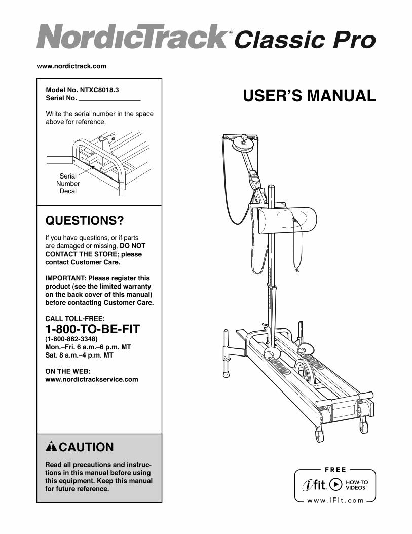
Serial Number Decal
www.nordictrack.com
CAUTIONRead all precautions and instruc-tions in this manual before using this equipment. Keep this manual for future reference.
Model No. NTXC8018.3Serial No.
Write the serial number in the space above for reference.
QUESTIONS?If you have questions, or if parts are damaged or missing, DO NOT CONTACT THE STORE; please contact Customer Care.
IMPORTANT: Please register this product (see the limited warranty on the back cover of this manual) before contacting Customer Care.
CALL TOLL-FREE:1-800-TO-BE-FIT(1-800- 862-3348)Mon.�–Fri. 6 a.m.�–6 p.m. MTSat. 8 a.m.�–4 p.m. MT
ON THE WEB:www.nordictrackservice.com

2NORDICTRACK is a registered trademark of ICON IP, Inc.
WARNING DECAL PLACEMENT
TABLE OF CONTENTS
This drawing shows the location(s) of the warning decal(s). If a decal is missing or illegible, call the tele-phone number on the front cover of this manual and request a free replacement decal. Apply the decal in the location shown. Note: The decal(s) may not be shown at actual size.
WARNING DECAL PLACEMENT . . . . . . . . . . . . . . . . . . . . . . . . . . . . . . . . . . . . . . . . . . . . . . . . . . . . . . . . . . . . . . .2IMPORTANT PRECAUTIONS . . . . . . . . . . . . . . . . . . . . . . . . . . . . . . . . . . . . . . . . . . . . . . . . . . . . . . . . . . . . . . . . . .3BEFORE YOU BEGIN. . . . . . . . . . . . . . . . . . . . . . . . . . . . . . . . . . . . . . . . . . . . . . . . . . . . . . . . . . . . . . . . . . . . . . . .4ASSEMBLY . . . . . . . . . . . . . . . . . . . . . . . . . . . . . . . . . . . . . . . . . . . . . . . . . . . . . . . . . . . . . . . . . . . . . . . . . . . . . . . .5HOW TO ADJUST THE SKI EXERCISER . . . . . . . . . . . . . . . . . . . . . . . . . . . . . . . . . . . . . . . . . . . . . . . . . . . . . . . .8HOW TO USE THE SKI EXERCISER. . . . . . . . . . . . . . . . . . . . . . . . . . . . . . . . . . . . . . . . . . . . . . . . . . . . . . . . . . . .9MAINTENANCE AND STORAGE . . . . . . . . . . . . . . . . . . . . . . . . . . . . . . . . . . . . . . . . . . . . . . . . . . . . . . . . . . . . . .12TROUBLESHOOTING . . . . . . . . . . . . . . . . . . . . . . . . . . . . . . . . . . . . . . . . . . . . . . . . . . . . . . . . . . . . . . . . . . . . . .14EXERCISE GUIDELINES . . . . . . . . . . . . . . . . . . . . . . . . . . . . . . . . . . . . . . . . . . . . . . . . . . . . . . . . . . . . . . . . . . . .16PART LIST. . . . . . . . . . . . . . . . . . . . . . . . . . . . . . . . . . . . . . . . . . . . . . . . . . . . . . . . . . . . . . . . . . . . . . . . . . . . . . . .18EXPLODED DRAWING. . . . . . . . . . . . . . . . . . . . . . . . . . . . . . . . . . . . . . . . . . . . . . . . . . . . . . . . . . . . . . . . . . . . . .19ORDERING REPLACEMENT PARTS . . . . . . . . . . . . . . . . . . . . . . . . . . . . . . . . . . . . . . . . . . . . . . . . . . . . . . . . . .20LIMITED WARRANTY. . . . . . . . . . . . . . . . . . . . . . . . . . . . . . . . . . . . . . . . . . . . . . . . . . . . . . . . . . . . . . . . . . . . . . .20

3
IMPORTANT PRECAUTIONS
WARNING: To reduce the risk of serious injury, read all important precautions and instructions in this manual and all warnings on your ski exerciser before using your ski exerciser. ICON assumes no responsibility for personal injury or property damage sustained by or through the use of this product.
1. Before beginning any exercise program, consult your physician. This is especially important for persons over age 35 or per-sons with pre-existing health problems.
2. Use the ski exerciser only as described in this manual.
3. It is the responsibility of the owner to ensure that all users of the ski exerciser are adequately informed of all precautions.
4. The ski exerciser is intended for home use only. Do not use the ski exerciser in a com-mercial, rental, or institutional setting.
5. Keep the ski exerciser indoors, away from moisture and dust. Do not put the ski exer-ciser in a garage or covered patio, or near water.
6. Place the ski exerciser on a level surface, with a mat beneath it to protect the floor or carpet. Make sure that there is at least 2 ft. (0.6 m) of clearance around the ski exerciser.
7. Inspect and properly tighten all parts regu-larly. Replace any worn parts immediately.
8. Keep children under age 12 and pets away from the ski exerciser at all times.
9. Wear appropriate clothes while exercising; do not wear loose clothes that could become caught on the ski exerciser. Always wear athletic shoes for foot protection.
10. The ski exerciser should not be used by per-sons weighing more than 250 lbs. (113 kg).
11. Keep hands and feet away from moving parts of the ski exerciser.
12. The pulley will become hot during use (see page 4 to identify the pulley). Avoid touching the pulley immediately after use.
13. The heart rate monitor is not a medical device. Various factors may affect the accu-racy of heart rate readings. The heart rate monitor is intended only as an exercise aid in determining heart rate trends in general.
14. Over exercising may result in serious injury or death. If you feel faint or if you experience pain while exercising, stop immediately and cool down.
4
Congratulations for selecting the innovative NORDICTRACK® CLASSIC PRO ski exerciser. Cross-country skiing is one of the most effective exercises for increasing cardiovascular tness, building endurance, and toning the entire body. The CLASSIC PRO ski exerciser features smooth skis, upper-body arm cords, and adjustable resistance designed to let you enjoy this dynamic exercise in the convenience and privacy of your home.
For your bene t, read this manual carefully before you use the ski exerciser. If you have questions after
reading this manual, please see the front cover of this manual. To help us assist you, note the product model number and serial number before contacting us. The model number and the location of the serial number decal are shown on the front cover of this manual.
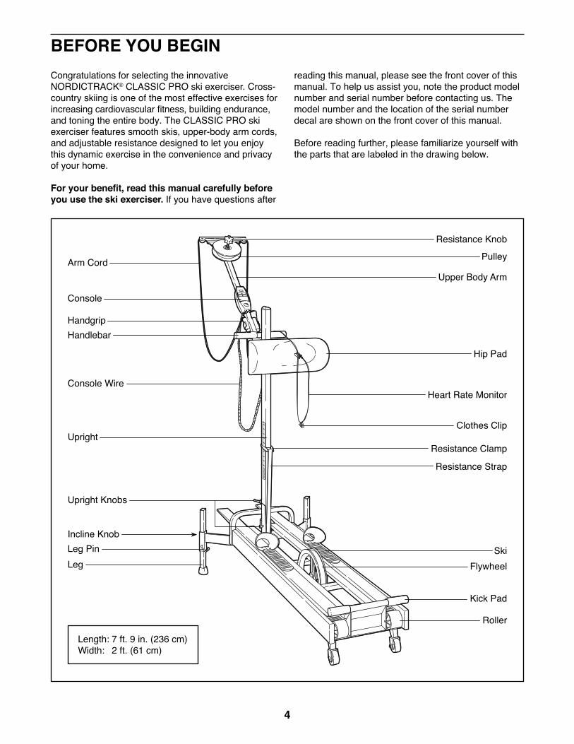
Before reading further, please familiarize yourself with the parts that are labeled in the drawing below.
Handgrip
Hip Pad
Heart Rate Monitor
Clothes Clip
Resistance Clamp
Resistance Strap
SkiFlywheel
Kick Pad
Roller
Upper Body Arm
Pulley
Upright Knobs
Incline KnobLeg PinLeg
Resistance Knob
Handlebar
Console
Console Wire
Upright
Arm Cord
BEFORE YOU BEGIN
Length: 7 ft. 9 in. (236 cm)Width: 2 ft. (61 cm)
5
�• Assembly requires two persons.
�• Place all parts in a cleared area and remove the packing materials. Do not dispose of the packing materials until you complete all assembly steps.
�• Assembly requires the included tool(s).
Assembly may be easier if you have a set of wrenches. To avoid damaging parts, do not use power tools.
ASSEMBLY
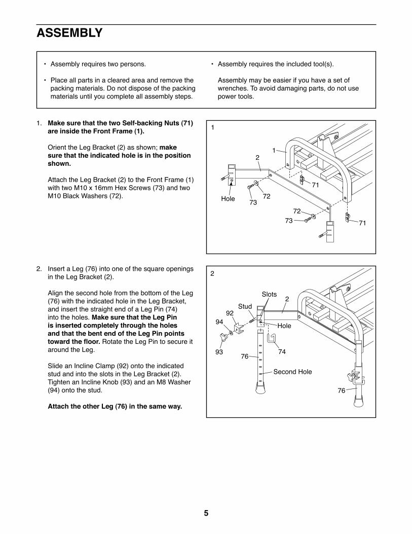
1. Make sure that the two Self-backing Nuts (71) are inside the Front Frame (1).
Orient the Leg Bracket (2) as shown; make sure that the indicated hole is in the position shown.
Attach the Leg Bracket (2) to the Front Frame (1) with two M10 x 16mm Hex Screws (73) and two M10 Black Washers (72). Hole
StudSlots
Hole
Second Hole
73
73
2
2
1
1
72
7271
71
2. Insert a Leg (76) into one of the square openings in the Leg Bracket (2).
Align the second hole from the bottom of the Leg (76) with the indicated hole in the Leg Bracket, and insert the straight end of a Leg Pin (74) into the holes. Make sure that the Leg Pin is inserted completely through the holes and that the bent end of the Leg Pin points toward the floor. Rotate the Leg Pin to secure it around the Leg.
Slide an Incline Clamp (92) onto the indicated stud and into the slots in the Leg Bracket (2). Tighten an Incline Knob (93) and an M8 Washer (94) onto the stud.
Attach the other Leg (76) in the same way.
9294
93 76
76
74
2

6
33. Lift the Upper Body Arm (27) slightly so that it will not catch on the Front Frame (1), and raise the Upright (16) to the position shown; the Upright will snap into place when it is positioned correctly.
Make sure that the M8 Push Nut (18) is between the Upright and the Front Frame.
Tighten the upper Upright Knob (17). Note: Each Upright Knob is like a wrench; turn the Upright Knob clockwise, pull it away from the Upright (16), turn it counterclockwise, push it toward the Upright, and then turn it clockwise again. Repeat this procedure until the Upright Knob is tight.
Next, tighten the lower Upright Knob (17). Note: When tightening the lower Upright Knob, use the assembly tool to hold the head of the M8 x 42mm Hex Bolt (not shown) onto which the Upright Knob is threaded.
4. Raise the Upper Body Arm (27) to position as shown. Make sure that the posts on the Snap Button (40) are fully extended and locked into position on both sides of the Hip Pad Slide (42).
4
27 16
17
27
4042
17
181
7
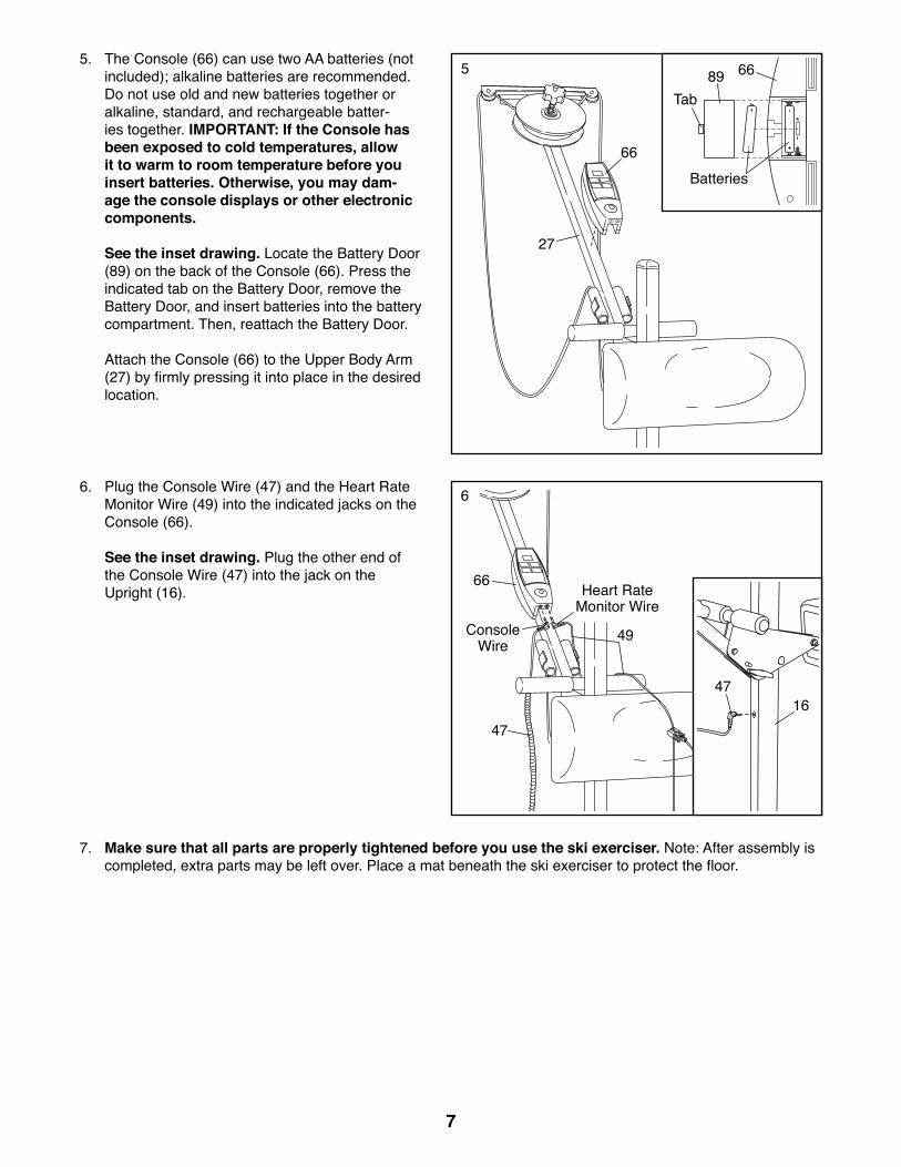
5. The Console (66) can use two AA batteries (not included); alkaline batteries are recommended. Do not use old and new batteries together or alkaline, standard, and rechargeable batter-ies together. IMPORTANT: If the Console has been exposed to cold temperatures, allow it to warm to room temperature before you insert batteries. Otherwise, you may dam-age the console displays or other electronic components.
See the inset drawing. Locate the Battery Door (89) on the back of the Console (66). Press the indicated tab on the Battery Door, remove the Battery Door, and insert batteries into the battery compartment. Then, reattach the Battery Door.
Attach the Console (66) to the Upper Body Arm (27) by firmly pressing it into place in the desired location.
5
6. Plug the Console Wire (47) and the Heart Rate Monitor Wire (49) into the indicated jacks on the Console (66).
See the inset drawing. Plug the other end of the Console Wire (47) into the jack on the Upright (16).
7. Make sure that all parts are properly tightened before you use the ski exerciser. Note: After assembly is completed, extra parts may be left over. Place a mat beneath the ski exerciser to protect the floor.
66
66
49
47
Console Wire
Heart Rate Monitor Wire
27
Batteries
6689Tab
6
4716

8
HOW TO ADJUST THE SKI RESISTANCE
CAUTION: Always dismount the ski exerciser before adjusting the resistance of the skis.
To increase the resis-tance of the skis, slide the Resistance Clamp (85) to a higher position on the Upright (16). To decrease the resistance, slide the Resistance Clamp to a lower position.
HOW TO ADJUST THE ARM CORD RESISTANCE
To adjust the resistance of the Arm Cord (23), turn the Resistance Knob (39) clockwise to increase the resistance, or counterclockwise to decrease the resistance. Note: As you turn the Resistance Knob, the numbered Resistance Scale Decal (88) will protrude through the Knob to show the resistance setting.
HOW TO ADJUST THE ARM CORD LENGTH
When the Arm Cord (23) is adjusted to the proper length, your arms should extend just behind your hips when you use the Arm Cord.
To adjust the length of the Arm Cord (23), retie the knot inside each Handgrip (24).
For greater adjustments in the length of the Arm Cord (23), add one loop of the Arm Cord around the pulley, or remove one loop from the pulley.
HOW TO ADJUST THE HIP PAD POSITION
The Hip Pad (53) should be at hip level, about one inch below your navel. The Hip Pad should be high enough that it does not restrict leg movement, and low enough that it does not press against your abdomen.
Loosen the Adjustment Knob (41) on each side of the Hip Pad Slide (42), and slide the Hip Pad Slide to the desired position. Then, firmly retighten both Adjustment Knobs.
HOW TO ADJUST THE ELEVATION
Increasing the elevation of the ski exerciser will simulate uphill skiing. This will further develop the quad-riceps muscles on the fronts of your thighs, elevate your heart rate more quickly, and provide a more intense workout.
To adjust the elevation, first loosen the Incline Knob (93) in front of one of the Legs (76). Insert the straight end of a Leg Pin (74) into the hole in the Leg Bracket (2) and one of the holes in the Leg. Make sure that the Leg Pin is inserted completely through the holes and that the bent end of the Leg Pin points toward the floor. Rotate the Leg Pin to secure it around the Leg. Retighten the Incline Knob.
Repeat this process with the other Leg (not shown). Make sure that both Legs are at the same height.
85
39
35
8823
23 24 25
76
93
2 74
Knot
16
23 23
41 42
53
HOW TO ADJUST THE SKI EXERCISER
WARNING: The Pulley (35) will become hot during use. Avoid touching the Pulley immediately after use.
9
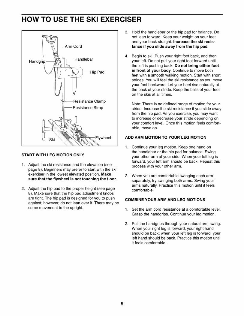
START WITH LEG MOTION ONLY
1. Adjust the ski resistance and the elevation (see page 8). Beginners may prefer to start with the ski exerciser in the lowest elevated position. Make sure that the flywheel is not touching the floor.
2. Adjust the hip pad to the proper height (see page 8). Make sure that the hip pad adjustment knobs are tight. The hip pad is designed for you to push against; however, do not lean over it. There may be some movement to the upright.
3. Hold the handlebar or the hip pad for balance. Do not lean forward. Keep your weight on your feet and your back straight. Increase the ski resis-tance if you slide away from the hip pad.
4. Begin to ski. Push your right foot back, and then your left. Do not pull your right foot forward until the left is pushing back. Do not bring either foot in front of your body. Continue to move both feet with a smooth walking motion. Start with short strides. You will feel the ski resistance as you move your foot backward. Let your heel rise naturally at the back of your stride. Keep the balls of your feet on the skis at all times.
Note: There is no defined range of motion for your stride. Increase the ski resistance if you slide away from the hip pad. As you exercise, you may want to increase or decrease your stride depending on your comfort level. Once this motion feels comfort-able, move on.
ADD ARM MOTION TO YOUR LEG MOTION
1. Continue your leg motion. Keep one hand on the handlebar or the hip pad for balance. Swing your other arm at your side. When your left leg is forward, your left arm should be back. Repeat this process with your other arm.
2. When you are comfortable swinging each arm separately, try swinging both arms. Swing your arms naturally. Practice this motion until it feels comfortable.
COMBINE YOUR ARM AND LEG MOTIONS
1. Set the arm cord resistance at a comfortable level. Grasp the handgrips. Continue your leg motion.
2. Pull the handgrips through your natural arm swing. When your right leg is forward, your right hand should be back; when your left leg is forward, your left hand should be back. Practice this motion until it feels comfortable.
HOW TO USE THE SKI EXERCISER
Arm Cord
HandlebarHandgrip
Hip Pad
Ski Flywheel
Resistance ClampResistance Strap

10
The following tips will help you coordinate your arm and leg motions:
1. If combining the arm and leg motions is difficult, keep practicing the leg motion. Incorporate the arm motion only when you feel comfortable with the leg motion.
2. When you incorporate the arm motion, try to swing your arms naturally. Allow one arm to pull the other arm forward. Keep the arm cord taught.
3. Keep your waist in contact with the hip pad at all times to hold back your forward motion. If you feel that you are sliding away from the hip pad, increase the ski resistance.
4. Resistance is felt only when you push your feet backward. Always keep your weight on the ski you are pushing backward. Avoid leaning forward. Keep your weight over your feet, your shoulders back, and your head up. Find a focal point; this will help you keep your head up and your back straight.

11
CONSOLE FEATURES
The console has five independent displays that provide continuous exercise feedback.
Pulse�—This mode displays your heart rate in beats per minute when the heart rate monitor is worn.
Time�—This mode displays the length of time that you have exercised.
Speed�—This mode displays your approximate pace, in miles per hour.
Calories�—This mode displays the approximate num-ber of calories you have burned during your workout.
Distance�—This mode displays the approximate dis-tance you have skied, in miles.
BATTERY INSTALLATION
Before the console can be operated, two AA batteries must be installed. To install batteries, see assembly step 5 on page 7.
HOW TO OPERATE THE CONSOLE
If there is a sheet of plastic on the console, remove the plastic.
1. To turn on the power, press the reset button or begin skiing.
2. To use the pulse mode, you must wear the heart rate monitor. Plug the heart rate monitor into the jack on the bottom of the console. Rub your left ear lobe several times with your thumb and index finger and then clip the heart rate monitor onto your left ear lobe. Slide the metal clothes clip onto your col-lar to prevent excessive movement of the wire.
When your pulse is detected, the small heart-shaped indicator in the pulse display will flash and your pulse will be displayed.
If your pulse is not displayed after a few seconds, make sure that the heart rate monitor is plugged into the console. In addition, make sure that the heart rate monitor is properly attached to your left ear lobe. It may be necessary to reposition the heart rate monitor a few times to find the best posi-tion. The heart rate monitor is more accurate when used on your left ear lobe and when you are stand-ing still.
3. To reset the display, press the reset button.
4. To turn off the power, simply wait for a few minutes. If the ski exerciser is not used and the console button is not pressed, the power will turn off automatically.

12
Inspect and tighten all parts each time you use the ski exerciser.
CLEANING THE SKI EXERCISER
Wipe the ski exerciser with a clean, dry cloth after each workout to remove perspiration and dirt. A household window cleaner may be used to clean the chrome and black metal surfaces.
Wipe the wood with a clean, dry cloth to remove per-spiration and dirt after each use. Use a wood furniture polish or wax to protect the wood finish and prevent drying.
If the bottoms of the skis become marked from con-tact with the drive rollers, wipe them with a clean, dry cloth. Use mineral spirits to remove stubborn marks. For a smooth gliding action, carefully rub paraffin wax only on the sides of the skis. NEVER polish or wax the bottoms of the skis. The skid plates built into the sides of the skis are designed to wear down and leave a light coating on the sides of the skis. These plates do not need to be replaced.
LUBRICATING THE RESISTANCE PAD
The leather resistance pad beneath the pulley has been oiled for quiet, smooth braking action. However, the pad will require re-oiling if it dries due to its sur-roundings. We recommend inspecting the resistance pad every three months.
1. Place a cloth or a piece of plastic under the ski exerciser to protect your floor.
2. See the inset drawing. Inspect the Thrust Washer (37). Lightly oil the Thrust Washer if it is not greasy.
Fully loosen but do not remove the Resistance Knob (39). Lift the Pulley (35) and roughen the top of the leather Resistance Pad (32) with 100-grit sandpaper or a file.
3. Spread one or two drops of light household oil on the resistance pad. DO NOT OVER-OIL. Excess oil may spray out when the pulley is spinning. Place a pencil between the pulley and the resistance pad and let the oil absorb overnight.
4. Wipe any excess oil away from the area around the resistance pad. Tighten the resistance knob.
Inspect the bottom of the pulley. If the resistance disk (located above the resistance pad) has grooves worn into it, it should be replaced. To order replacement parts, see the back of this manual.
CARING FOR THE RESISTANCE STRAP AND THE FLYWHEEL
Resistance strap and flywheel maintenance should be performed once a month at the same time. Follow the steps below.
1. Place a cloth or a piece of plastic under the ski exerciser to protect your floor.
2. Set the ski resistance to the lowest setting.
3. Slide the resistance strap off the side of the flywheel.
4. Wipe the surface of the flywheel with a clean cloth dampened with rubbing alcohol.
5. Check the groove of the flywheel for any rust or corrosion.
6. Use fine to very fine steel wool to spot rub any rust or corrosion. Clean the entire flywheel with steel wool if necessary.
7. Wipe the flywheel with a clean, dry cloth to remove any residue. NEVER place oil between the resis-tance strap and the flywheel; this will damage the resistance strap.
MAINTENANCE AND STORAGE
39
32Oil
35
37

13
8. Slide the U-bolt Cover (64) to the right and check the tightness of the M6 Nuts (67) on the right side of the Flywheel (54). If nec-essary, tighten the Nuts evenly with a wrench. CAUTION: Do not overtighten the Nuts; this can break the M6 U-bolt (not shown).
9. Slide the resistance strap back onto the flywheel. Note: If the resistance strap is frayed on both sides, it may be necessary to replace it. To order replace-ment parts, see the back of this manual.
GENERAL LUBRICATION
If the front or rear Rollers (15) begin to squeak, a drop of light house-hold oil may be needed on the Roller Axles (70). IMPORTANT: The drive roll-ers located near the flywheel are internally lubricated and should NOT be oiled. Follow the instructions below to apply oil.
1. Place a cloth or a piece of plastic under the ski exerciser to protect your floor.
2. Put a drop of light household oil on each side of each roller, and then spin each roller.
STORAGE
Set the ski resistance to the lowest setting and remove any accessories before folding and storing your ski exerciser. When storing the ski exerciser for more than 30 days, we recommend the following:
1. Remove the batteries from the console.
2. Slide the resistance strap off the flywheel.
3. Lightly coat the groove of the flywheel with light household oil to protect the metal from corrosion. IMPORTANT: Never place oil on the resistance strap. Only the flywheel should be oiled and then cleaned before the resistance strap is reat-tached. Do not place the resistance strap on the oiled flywheel.
4. Loosen the two adjustment knobs on the hip pad slide.
5. Move the hip pad slide so that the top is about seven inches below the top of the upright. Retighten both of the adjustment knobs and pivot the hip pad upward.
6. Support the upper body arm with one hand. Use the other hand to depress the snap button on either side of the hip pad slide. Lower the upper body arm until it rests against the upright.
7. Hold the upright with one hand. Loosen the two upright knobs. Lower the upright until it rests on the base. The hip pad should just touch the tops of the skis.
8. Upon removal from storage, clean the flywheel with rubbing alcohol. Slide the resistance strap back onto the flywheel.
64
67
54
FlywheelOil
15
Oil
70

14
TROUBLESHOOTING Most ski exerciser problems can be solved by following the steps below. Find the symptom that applies, and follow the steps listed. If further assis-tance is needed, please see the front cover of this manual.
SYMPTOM: The console does not function properly.
a. Make sure that both ends of the console wire are fully plugged in (see assembly step 6 on page 7).
b. If the console does not function properly, or if the display becomes faint, the batteries should be replaced. See assembly step 5 on page 7 for replacement instructions.
SYMPTOM: The arm cords are tangled.
a. Detach the handgrips by untying the knots inside of the handgrips and removing the M6 Washers (25) (see HOW TO ADJUST THE ARM CORD LENGTH on page 8).
Take the ends of the Arm Cord (23) out of the Small Pulleys (28) and unwind the Arm Cord from the Pulley (35). Notice how the Arm Cord goes into the Pulley. Drape both ends of the Arm Cord over the hip pad. Make sure that the ends of the Arm Cord are even.
b. Locate cord A. Wrap it counterclockwise around the Pulley (35) until there is no more cord to wind. Do not be concerned if it looks tangled; it will smooth out later.
c. Pass the end of cord A from left to right through the right Small Pulley (28). Pull cord A to wrap cord B around the Pulley (35).
d. Feed the end of cord B from right to left through the left Small Pulley (28). Pull cord B until the end of cord B is even with the end of cord A. With a cord in each hand, work the Arm Cord (23) back and forth until it is wrapped evenly around the Pulley (35).
e. To reattach each handgrip, thread the Arm Cord (23) into the small hole in the handgrip, slide an M6 Washer (25) onto the Arm Cord, and tie a figure-eight knot as shown near the end of the Arm Cord.
Note: To adjust the length of the Arm Cord (23), see HOW TO ADJUST THE ARM CORD LENGTH on page 8.
SYMPTOM: The arm cord assembly makes a chat-tering or screeching sound or the resistance knob loosens.
a. Check the order of the parts in the pulley assem-bly, and confirm that all parts are present (see the EXPLODED DRAWING on page 19). The parts from the Pulley (35) to the Resistance Knob (39) should be as follows: M10 Washer (36), Thrust Washer (37), M10 Washer (36), and Spring (38).
b. Roughen the top of the leather resistance pad with 100-grit sandpaper. Oil the resistance pad with one or two drops of light household oil. Spread the oil over the resistance pad.
c. Oil the M10 Washers (36) and the Thrust Washer (37) if needed.
WARNING: The pulley will get hot during use. Avoid touching the pulley immediately after use.
28 2835 35
23 B A
28 28
15
SYMPTOM: The flywheel and/or the resistance strap offers no resistance.
a. Check the routing of the resistance strap.
b. Make sure that the flywheel is tight. Remove the U-bolt cover from the flywheel (see step 8 on page 13). Evenly tighten the two M6 nuts located on the right side of the flywheel.
SYMPTOM: The skis slip.
a. Wipe off any excess oil.
b. Clean the bottoms of the skis with a dry cloth and a small amount of mineral spirits or paint thinner.
c. Make sure that the flywheel is tight. Remove the U-bolt cover from the flywheel (see step 8 on page 13). Evenly tighten the two M6 nuts located on the right side of the flywheel.
SYMPTOM: The rollers squeak or stick.
a. See GENERAL LUBRICATION on page 13.

16
EXERCISE GUIDELINES
These guidelines will help you to plan your exercise program. For detailed exercise information, obtain a reputable book or consult your physician. Remember, proper nutrition and adequate rest are essential for successful results.
EXERCISE INTENSITY
Whether your goal is to burn fat or to strengthen your cardiovascular system, exercising at the proper inten-sity is the key to achieving results. You can use your heart rate as a guide to find the proper intensity level. The chart below shows recommended heart rates for fat burning and aerobic exercise.
To find the proper intensity level, find your age at the bottom of the chart (ages are rounded off to the near-est ten years). The three numbers listed above your age define your �“training zone.�” The lowest number is the heart rate for fat burning, the middle number is the heart rate for maximum fat burning, and the highest number is the heart rate for aerobic exercise.
Burning Fat�—To burn fat effectively, you must exer-cise at a low intensity level for a sustained period of time. During the first few minutes of exercise, your body uses carbohydrate calories for energy. Only after the first few minutes of exercise does your body begin to use stored fat calories for energy. If your goal is to burn fat, adjust the intensity of your exercise until your heart rate is near the lowest number in your training zone. For maximum fat burning, exercise with your heart rate near the middle number in your training zone.
Aerobic Exercise�—If your goal is to strengthen your cardiovascular system, you must perform aerobic exercise, which is activity that requires large amounts of oxygen for prolonged periods of time. For aerobic exercise, adjust the intensity of your exercise until your heart rate is near the highest number in your training zone.
WORKOUT GUIDELINES
Warming Up�—Start with 5 to 10 minutes of stretch-ing and light exercise. A warm-up increases your body temperature, heart rate, and circulation in preparation for exercise.
Training Zone Exercise�—Exercise for 20 to 30 min-utes with your heart rate in your training zone. (During the first few weeks of your exercise program, do not keep your heart rate in your training zone for longer than 20 minutes.) Breathe regularly and deeply as you exercise �—never hold your breath.
Cooling Down�—Finish with 5 to 10 minutes of stretch-ing. Stretching increases the flexibility of your muscles and helps to prevent post-exercise problems.
EXERCISE FREQUENCY
To maintain or improve your condition, complete three workouts each week, with at least one day of rest between workouts. After a few months of regular exer-cise, you may complete up to five workouts each week, if desired. Remember, the key to success is to make exercise a regular and enjoyable part of your everyday life.
WARNING: Before beginning this or any exercise program, consult your physi-cian. This is especially important for persons over age 35 or persons with pre-existing health problems.
The heart rate monitor is not a medical device. Various factors may affect the accuracy of heart rate readings. The heart rate monitor is intended only as an exercise aid in determin-ing heart rate trends in general.

17
SUGGESTED STRETCHES
The correct form for several basic stretches is shown at the right. Move slowly as you stretch �—never bounce.
1. Toe Touch Stretch
Stand with your knees bent slightly and slowly bend forward from your hips. Allow your back and shoulders to relax as you reach down toward your toes as far as possible. Hold for 15 counts, then relax. Repeat 3 times. Stretches: Hamstrings, back of knees and back.
2. Hamstring Stretch
Sit with one leg extended. Bring the sole of the opposite foot toward you and rest it against the inner thigh of your extended leg. Reach toward your toes as far as possible. Hold for 15 counts, then relax. Repeat 3 times for each leg. Stretches: Hamstrings, lower back and groin.
3. Calf/Achilles Stretch
With one leg in front of the other, reach forward and place your hands against a wall. Keep your back leg straight and your back foot flat on the floor. Bend your front leg, lean forward and move your hips toward the wall. Hold for 15 counts, then relax. Repeat 3 times for each leg. To cause further stretching of the achilles tendons, bend your back leg as well. Stretches: Calves, achilles tendons and ankles.
4. Quadriceps Stretch
With one hand against a wall for balance, reach back and grasp one foot with your other hand. Bring your heel as close to your buttocks as possible. Hold for 15 counts, then relax. Repeat 3 times for each leg. Stretches: Quadriceps and hip muscles.
5. Inner Thigh Stretch
Sit with the soles of your feet together and your knees outward. Pull your feet toward your groin area as far as possible. Hold for 15 counts, then relax. Repeat 3 times. Stretches: Quadriceps and hip muscles.
1
2
3
4
5
18
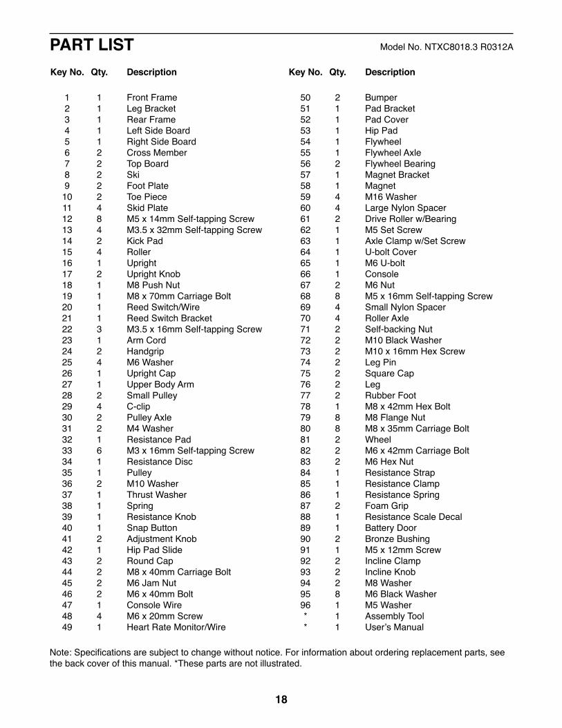
1 1 Front Frame 2 1 Leg Bracket 3 1 Rear Frame 4 1 Left Side Board 5 1 Right Side Board 6 2 Cross Member 7 2 Top Board 8 2 Ski 9 2 Foot Plate 10 2 Toe Piece 11 4 Skid Plate 12 8 M5 x 14mm Self-tapping Screw 13 4 M3.5 x 32mm Self-tapping Screw 14 2 Kick Pad 15 4 Roller 16 1 Upright 17 2 Upright Knob 18 1 M8 Push Nut 19 1 M8 x 70mm Carriage Bolt 20 1 Reed Switch/Wire 21 1 Reed Switch Bracket 22 3 M3.5 x 16mm Self-tapping Screw 23 1 Arm Cord 24 2 Handgrip 25 4 M6 Washer 26 1 Upright Cap 27 1 Upper Body Arm 28 2 Small Pulley 29 4 C-clip 30 2 Pulley Axle 31 2 M4 Washer 32 1 Resistance Pad 33 6 M3 x 16mm Self-tapping Screw 34 1 Resistance Disc 35 1 Pulley 36 2 M10 Washer 37 1 Thrust Washer 38 1 Spring 39 1 Resistance Knob 40 1 Snap Button 41 2 Adjustment Knob 42 1 Hip Pad Slide 43 2 Round Cap 44 2 M8 x 40mm Carriage Bolt 45 2 M6 Jam Nut 46 2 M6 x 40mm Bolt 47 1 Console Wire 48 4 M6 x 20mm Screw 49 1 Heart Rate Monitor/Wire
50 2 Bumper 51 1 Pad Bracket 52 1 Pad Cover 53 1 Hip Pad 54 1 Flywheel 55 1 Flywheel Axle 56 2 Flywheel Bearing 57 1 Magnet Bracket 58 1 Magnet 59 4 M16 Washer 60 4 Large Nylon Spacer 61 2 Drive Roller w/Bearing 62 1 M5 Set Screw 63 1 Axle Clamp w/Set Screw 64 1 U-bolt Cover 65 1 M6 U-bolt 66 1 Console 67 2 M6 Nut 68 8 M5 x 16mm Self-tapping Screw 69 4 Small Nylon Spacer 70 4 Roller Axle 71 2 Self-backing Nut 72 2 M10 Black Washer 73 2 M10 x 16mm Hex Screw 74 2 Leg Pin 75 2 Square Cap 76 2 Leg 77 2 Rubber Foot 78 1 M8 x 42mm Hex Bolt 79 8 M8 Flange Nut 80 8 M8 x 35mm Carriage Bolt 81 2 Wheel 82 2 M6 x 42mm Carriage Bolt 83 2 M6 Hex Nut 84 1 Resistance Strap 85 1 Resistance Clamp 86 1 Resistance Spring 87 2 Foam Grip 88 1 Resistance Scale Decal 89 1 Battery Door 90 2 Bronze Bushing 91 1 M5 x 12mm Screw 92 2 Incline Clamp 93 2 Incline Knob 94 2 M8 Washer 95 8 M6 Black Washer 96 1 M5 Washer * 1 Assembly Tool * 1 User�’s Manual
Key No. Qty. Description Key No. Qty. Description
PART LIST Model No. NTXC8018.3 R0312A
Note: Specifications are subject to change without notice. For information about ordering replacement parts, see the back cover of this manual. *These parts are not illustrated.

19
45
31
12
3
4
5 6
6
7
7
8
910
11
9
8
10
1111
1213
13
13
13
1214
14
1515
15
1516
171819
2021
22
2324
25
26
2728
28
2929
29
29
303233 222231
33
343536
37
3839
41
41
40
42
43
43
4444
45
46
4648
4850
50515253
5455
56
57
58
5960
6160
59
56
5960
6160
5962
6364
65
25 6768
68
68
6869
70
7069
71
71
7273
7273
74
74
7575
76 77
17
79
7879
7979
80
80
8081
81
8283
84
85
86
87
4749
6687
88
8990
90
91
92
94
93
92 9493
95
96
3333
EXPLODED DRAWING Model No. NTXC8018.3 R0312A

Part No. 329538 R0312A Printed in China © 2012 ICON IP, Inc.
To order replacement parts, please see the front cover of this manual. To help us assist you, be prepared to provide the following information when contacting us:
�• the model number and serial number of the product (see the front cover of this manual)
�• the name of the product (see the front cover of this manual)
�• the key number and description of the replacement part(s) (see the PART LIST and the EXPLODED DRAWING near the end of this manual)
ORDERING REPLACEMENT PARTS
ICON Health & Fitness, Inc. (ICON) warrants this product to be free from defects in workmanship and material, under normal use and service conditions. Parts and labor are warranted for one (1) year from the date of purchase.
This warranty extends only to the original purchaser (customer). ICON�’s obligation under this warranty is limited to repairing or replacing, at ICON�’s option, the product through one of its authorized service centers. All repairs for which warranty claims are made must be preauthorized by ICON. If the product is shipped to a service center, freight charges to and from the service center will be the customer�’s responsibility. If replacement parts are shipped while the product is under warranty, the customer will be responsible for a minimal handling charge. For in-home service, the customer will be responsible for a minimal trip charge. This warranty does not extend to freight damage to the product. This warranty will automatically be voided if the product is used as a store display model, if the product is purchased or transported outside the USA, if all instructions in this manual are not followed, if the product is abused or improperly or abnormally used, or if the product is used for commercial or rental purposes. No other warranty beyond that speci cally set forth above is authorized by ICON.
ICON is not responsible or liable for indirect, special, or consequential damages arising out of or in con-nection with the use or performance of the product; damages with respect to any economic loss, loss of property, loss of revenues or pro ts, loss of enjoyment or use, or costs of removal or installation; or other consequential damages of any kind. Some states do not allow the exclusion or limitation of incidental or consequential damages. Accordingly, the above limitation may not apply to the customer.
The warranty extended hereunder is in lieu of any and all other warranties, and any implied warranties of merchantability or tness for a particular purpose are limited in their scope and duration to the terms set forth herein. Some states do not allow limitations on how long an implied warranty lasts. Accordingly, the above limitation may not apply to the customer.
This warranty provides speci c legal rights; the customer may have other rights that vary from state to state.
ICON Health & Fitness, Inc., 1500 S. 1000 W., Logan, UT 84321-9813
LIMITED WARRANTYIMPORTANT: You must register this product within 30 days of the purchase date to avoid added fees for service needed under warranty. Go to www.nordictrackservice.com/registration.