model oum960 uv analyzer/ model ousaf44 uv inline … · p/n 71002849 rev 3 ba924c/07/en/0609...
TRANSCRIPT

P/N 71002849 Rev 3
BA924C/07/en/0609
Operating Instructions
Model OUM960 UV Analyzer/
Model OUSAF44 UV Inline Sensor
Analyzer/Sensor to measure UV Spectral Absorbance

Model OUM960 with OUSAF 44 Inline Sensor
2

Model OUM960 with OUSAF 44 Inline Sensor
3
Table of Contents
1. SAFETY INSTRUCTIONS.................................................................................................................................................. 5
1.1 DESIGNATED USE........................................................................................................................................................................ 5 1.2 INSTALLATION, START-UP AND OPERATION..................................................................................................................................... 5 1.3 OPERATIONAL SAFETY.................................................................................................................................................................. 5 1.4 RETURN..................................................................................................................................................................................... 6
2. GENERAL INFORMATION .............................................................................................................................................. 7
2.1 HOW THE MODEL 960 UV ANALYZER WORKS ................................................................................................................................ 7 2.2 CONCENTRATION AND ABSORBANCE UNITS .................................................................................................................................... 7 2.3 EASY INTERFACING...................................................................................................................................................................... 7
3. INSTALLATION................................................................................................................................................................ 9
3.1 MODEL OUM960 ANALYZER INSTALLATION .................................................................................................................................. 9 3.2 MODEL OUM960 CABLES AND WIRING ...................................................................................................................................... 10 3.3 DC INPUT POWER OPTION......................................................................................................................................................... 11 3.4 MODEL OUSAF44 SENSOR INSTALLATION ................................................................................................................................... 12 3.5 CABLE OUK40 STRUCTURE AND TERMINATION OF MEASUREMENT CABLE ........................................................................................ 13 3.6 POST-CONNECTION CHECK........................................................................................................................................................ 14
4. OPERATION ................................................................................................................................................................... 15
4.1 QUICK OPERATION GUIDE.......................................................................................................................................................... 15 4.2 DISPLAY AND OPERATING ELEMENTS............................................................................................................................................ 15
4.2.1 Operating Elements ....................................................................................................................................................... 15 4.2.2 Operation Legend .......................................................................................................................................................... 16
4.3 LOCAL OPERATION.................................................................................................................................................................... 16 4.3.1 Measuring Mode............................................................................................................................................................ 16 4.3.2 Configuration Mode....................................................................................................................................................... 18
4.4 REMOTE OPERATION ................................................................................................................................................................. 19
5. COMMISSIONING.......................................................................................................................................................... 20
5.1 FUNCTION CHECK..................................................................................................................................................................... 20 5.2 SWITCHING ON ........................................................................................................................................................................ 20 5.3 ANALYZER CONFIGURATION AND OPERATION................................................................................................................................ 21
5.3.1 Factory Default Setting................................................................................................................................................... 22 5.3.2 Sensor Calibration.......................................................................................................................................................... 22
5.3.2.1 Liquid Calibration Procedure...................................................................................................................................... 22 5.3.2.2 Easycal
TM Set up and Calibration................................................................................................................................ 24
5.3.3 Change Pathlength Setting ............................................................................................................................................. 27 5.3.4 Setup Output Span......................................................................................................................................................... 27 5.3.5 Output Relay Set Point and Configuration....................................................................................................................... 28 5.3.6 Current Output Calibration ............................................................................................................................................ 30 5.3.7 Date and Time Setting.................................................................................................................................................... 30 5.3.8 Configuration and Use Digital Input ............................................................................................................................... 31 5.3.9 Process Control.............................................................................................................................................................. 32
5.3.9.1 Access of Process Control .......................................................................................................................................... 32 5.3.9.2 Baseline (AutoZero) ................................................................................................................................................... 32 5.3.9.3 Optical Zero .............................................................................................................................................................. 33 5.3.9.4 Lamp Switch ............................................................................................................................................................. 33 5.3.9.5 Optical Check............................................................................................................................................................ 33 5.3.9.6 Password Protection .................................................................................................................................................. 35

Model OUM960 with OUSAF 44 Inline Sensor
4
5.3.9.7 Process Value Correlation .......................................................................................................................................... 36
6. MAINTENANCE ............................................................................................................................................................. 39
6.1 MAINTENANCE OUTLINE............................................................................................................................................................ 39 6.2 MERCURY LAMP REPLACEMENT FOR OUSAF44 ............................................................................................................................ 40 6.3 OUSAF44 MEASUREMENT DETECTOR/FILTER REPLACEMENT......................................................................................................... 42 6.4 MEASUREMENT FILTER REPLACEMENT (EASYCAL™ ASSEMBLY)........................................................................................................ 43 6.5 MEASUREMENT FILTER REPLACEMENT (STANDARD AND CAL ROD ASSEMBLIES) .................................................................................. 44 6.6 SENSOR WAVELENGTH CHANGE.................................................................................................................................................. 45 6.7 SENSOR WINDOW AND GASKET REPLACEMENT.............................................................................................................................. 45 6.8 SENSORS WITHOUT PRECISION OPTICAL PATH LENGTH ADJUSTER OPTION ......................................................................................... 46 6.9 SENSORS WITH PRECISION OPTICAL PATH LENGTH ADJUSTER OPTION ............................................................................................... 47
7. REPLACEMENT PARTS LIST.......................................................................................................................................... 51
7.1 MODEL OUM960 UV ANALYZER ............................................................................................................................................... 51 7.2 MODEL OUSAF44 UV INLINE SENSOR /OUA260 FLOW CELL....................................................................................................... 51
8. TECHNICAL INFORMATION ........................................................................................................................................ 52
8.1 UV ANALYZER OUM960........................................................................................................................................................... 52 8.1.1 Input ............................................................................................................................................................................. 52 8.1.2 Output........................................................................................................................................................................... 52 8.1.3 Power Supply................................................................................................................................................................. 52 8.1.4 Performance .................................................................................................................................................................. 53 8.1.5 Environment.................................................................................................................................................................. 53 8.1.6 Mechanical Construction ............................................................................................................................................... 53
8.2 UV ABSORBANCE SENSOR OUSAF44........................................................................................................................................... 53 8.2.1 Input and Output........................................................................................................................................................... 53 8.2.2 Mechanic Construction.................................................................................................................................................. 53 8.2.3 Environment.................................................................................................................................................................. 55 8.2.4 Power Supply................................................................................................................................................................. 55 8.2.5 Optical Specifications ..................................................................................................................................................... 55
9. ORDERING INFORMATION .......................................................................................................................................... 56
9.1 UV ANALYZER OUM960........................................................................................................................................................... 56 9.2 UV ABSORBANCE SENSOR OUSAF44........................................................................................................................................... 57 9.3 MODEL OUA260 FLOW CELL .................................................................................................................................................... 58 9.4 MODEL OUK40 UV SENSOR CABLE SET ...................................................................................................................................... 59

Model OUM960 with OUSAF 44 Inline Sensor Safety Instructions
5
1. Safety Instructions
1.1 Designated Use
Integra Model OUM960 is an analyzer for determining the UV absorbance of a liquid medium.
The analyzer is particularly suited for use in the following areas:
• Bio-Technology industry
• Waste water processing
• Chemical processing industry
• Food industry
• Pharmaceutical industry
Any other use than the one described here compromises the safety of persons and the entire measuring system and is, therefore, not
permitted. The manufacturer is not liable for damage caused by improper or non-designated use.
1.2 Installation, Start-Up and Operation
Please note the following items:
• Installation, electrical connection, start-up, operation and maintenance of the measuring system must only be carried out by
trained technical personnel. The technical personnel must be authorized for the specified activities by the system operator.
• Technical personnel must have read and understood these Operating Instructions and must adhere to them.
• Before commissioning the entire measuring point, check all the connections for correctness. Ensure that electrical cables and
hose connections are not damaged.
• Do not operate damaged products and secure them against unintentional commissioning. Mark the damaged product as being
defective.
• Measuring point faults may only be rectified by authorized and specially trained personnel.
• If faults can not be rectified, the products must be taken out of service and secured against unintentional commissioning.
• Repairs not described in these Operating Instructions may only be carried out at the manufacturers or by the service
organization.
1.3 Operational Safety
Relevant regulations and standards have been met. As the user, you are responsible for complying with the following safety conditions:
• Installation instructions
• Local prevailing standards and regulations.
EMC
This instrument has been tested for electromagnetic compatibility in industrial use according to applicable standards.
Protection against interference as specified above is valid only for an instrument connected according to the instructions in these
Operating Instructions.

Model OUM960 with OUSAF 44 Inline Sensor Safety Instructions
6
1.4 Return
If the device requires repair, please contact your Endress+Hauser representative. Please use the original packaging, if possible.
Notes on safety icons and symbols
Safety icons
Warning!
This symbol alerts you to hazards. They can cause serious damage to the instrument or to persons if ignored.
Caution!
This symbol alerts you to possible faults which could arise from incorrect operation. They could cause damage to the
instrument if ignored.
Note!
This symbol indicates important items of information.
Electrical symbols
Direct Current (DC)
A terminal at which DC is applied or through which DC flows.
Alternating Current (AC)
A terminal at which (sine-form) AC is applied or through which AC flows.
Ground connecting A terminal is already grounded using a grounding system.
Protective earth terminal A terminal which must be grounded before other connections may be set up.
Alarm relay
Input
Output

Model OUM960 with OUSAF 44 Inline Sensor Installation
7
2. General Information
The Model OUM960 UV analyzer is used in conjunction with a Model OUSAF44 sensor to measure the spectral absorbance of process
liquid in the UV region of the electromagnetic spectrum.
Dependent upon the optical pathlength of the connected sensor, the instrument can measure up to 50 Optical Density (OD) units.
The Model OUM960 UV analyzer is manufactured from state of the art digital electronics. Plant interface is through quick disconnect
screw terminals on the back of the module. The user interface is comprised of a 6-button tactile feel keypad and 4 x 20 character
alphanumeric LCD display.
2.1 How the Model 960 UV Analyzer Works
The Model OUSAF44 sensor generates two photocurrent (nA) detector signals based upon the amount of UV energy present at its lamp
source (reference) and measurement point internally. The Model OUM960 unit computes the logarithmic ratio of these two signals and
determines the absorbance of the liquid passing through the sensor. The absorbance value is expressed in optical density units (OD) and
is displayed on the front panel. Two galvanic isolated analog current outputs, proportional to the OD reading, are simultaneously
transmitted for connection to other instrumentation and recording devices.
2.2 Concentration and Absorbance Units
The concentration of an optically absorbing material in a mixture can be determined since it is related to the amount of light absorbed
from a beam of light passing through it. The absorbance of a substance is directly proportional to the concentration of the material that
causes the absorption. The Lambert-Beer Law describes this relationship of absorbance (A) to concentration. Essentially, the amount of
radiation transmitted through the absorbing material decreases logarithmically with its increasing concentration.
Where IrIo
TA log1log == and
IoIrT =
The above assumes that the optical pathlength remains constant. The optical density (OD) however, is defined as Absorption per unit
length. Normalizing to an optical pathlength of 1cm, it follows that:
)(1 AL
OD=
Where OD = Optical Density
A = Absorbance
= pathlength in cm
2.3 Easy Interfacing
The Model OUM960 UV analyzer incorporates a front panel display and two analog current output signals. The display on the front
panel is an alphanumeric 4 x 20 character LCD. The display may be configured for process variable or analog current output
measurements. Optical Density (OD) readings are normalized to a 1cm pathlength.
There are two analog current outputs from the unit. The range of each can be independently set to be any range within the measurement
range of the instrument. One output is configured to operate with measurement baseline shift commands, while the other tracks full
scale of the instrument.

Model OUM960 with OUSAF 44 Inline Sensor Installation
8
The analog current outputs (4-20mA) will operate with loads up to 750 ohms. These outputs are galvanically isolated and conform to
NAMUR Standardi.
Model OUM960 is supplied as standard with four digital inputs and three digital output relays.
The digital inputs can be configured to perform a variety of functions such as baseline and sensor lamp off/on.
The outputs can be connected to a PLC for inclusion in a control scheme, for simple valve operation or for local indication (alarms) and
annunciation. Alarm status indication is provided on the front panel display.
All digital inputs are optically isolated.
i i NAMUR Standard Limit Detection when enabled is set to ERROR if the signal level is above 21 mA or below 3.6 mA for more than 4 seconds. The ERROR status is cleared
when the signal returns to the normal 4-20 mA range.

Model OUM960 with OUSAF 44 Inline Sensor Installation
9
3. Installation
3.1 Model OUM960 Analyzer Installation
Before starting installation, inspect the analyzer, sensor, and supplied cable set for any signs of shipping damage. Report any visual
damage or discrepancies to Endress+Hauser Conducta and the Shipper immediately.
The Model OUM960 Analyzer is a ¼ DIN enclosure which can be installed in a variety of panels, wall or bench top housings. Refer to
figure 3.1 for mounting dimensions. Mount or install the Analyzer into an enclosure or area that is not subject to excessive vibration or
shock and will protect the instrument from materials such as water and chemicals. Allow enough clearance behind it for cable access.
Figure 3.1: Model OUM960 Analyzer Mounting

Model OUM960 with OUSAF 44 Inline Sensor Installation
10
3.2 Model OUM960 Cables and Wiring
All wiring terminals are located on the back panel of the Model OUM960. The analyzer/sensor interconnection cables supplied with the
system have all been pre-terminated and labeled for ease of installation. The Model OUM960 has two (2) analog current outputs of 4 to
20mA. Both are capable of driving loads up to 750 ohms.
In addition to the analog outputs, three (3) galvanic isolated digital outputs (N.O.) are available. These outputs are rated for both AC and
DC voltages up to 280 volts at 125mA. These outputs are intended for dry contact or pilot applications.
123456789
101112
Con
nect
orPh
oeni
x C
ambi
on
Insert TerminalHere
Wire PinTerminal
Figure 3.2: Wire Terminal Preparations
Cables installed for signal connection (i.e. analog outputs, lamp fail output) should be shielded twisted pairs.
Warning!
When routing the cables, separate signal cables from power wiring!
Caution!
Use dry contact only when connect digital input to analyzer!
Refer Figure 3.3 for wiring connection.

Model OUM960 with OUSAF 44 Inline Sensor Installation
11
Figure 3.3: Model OUM960/OUSAF44 Wiring Diagram (AC Input Version)
3.3 DC Input Power Option
For instruments supplied for 24VDC operation, only the power input connection is changed. Figure 3.4 shows the connection detail for a
24VDC unit.
Input Power
+24VDCDC RTNGround
24 VDC
Figure 3.4: Integra DC Power Connection

Model OUM960 with OUSAF 44 Inline Sensor Installation
12
3.4 Model OUSAF44 Sensor Installation
Figure 3.5: Recommended Orientation for Sensor Installation
Sensors can be installed either directly in a process line or in a by-pass line. They can be mounted either vertically or horizontally. If
mounted horizontally, the sensor lamp and detector housings must be horizontal. This will insure that the optical window surfaces are in
a vertical position, which will help prevent build up on the window surfaces. The sensor should be located upstream of pressure
regulators. Operating sensors under pressure will help to avoid the possibility of air or gas bubble evolution, which can cause
measurement noise and error.
When installing, allow adequate space for the connection of cables at the ends of the lamp and detector housings. Access to these areas is
also important for connection/disconnection purposes. Sensor bodies should be supported when in line and care should be taken to
ensure they are protected against damage caused by external forces such as carts on adjacent walkways.
Figure 3.6: Typical OUSAF44/45/46 Sensor With Cables Connected.

Model OUM960 with OUSAF 44 Inline Sensor Installation
13
3.5 Cable OUK40 Structure and Termination of Measurement Cable
Figure 3.7: OUSAF44 Cable at Lamp Side
Figure 3.8: OUSAF44 Cable at Detector Side

Model OUM960 with OUSAF 44 Inline Sensor Installation
14
3.6 Post-Connection Check
After wiring up the electrical connection, carry out the following checks:
Device Status and Specifications
Remark
Is the analyzer or the cable externally damaged?
Visual inspection
Electrical connection Remarks
Remark
Are the installed cables strain-relieved?
No loops and cross-overs in the cable run?
Are the signal cables correctly connected according to the wiring
diagram?
Are all screw terminals tightened?
Are all cable entries installed, tightened and sealed?
Are the PE distributor rails grounded (if present)? Grounding at place
of installation
Grounding at place of installation
Caution!
Improper grounding will lead to unreliable measurement result!

Model OUM960 with OUSAF 44 Inline Sensor Operation
15
4. Operation
4.1 Quick Operation Guide
User has the following ways of operating the analyzer:
• On site via the keypad
• Via the digital input interface to perform process control functions remotely.
4.2 Display and Operating Elements
4.2.1 Operating Elements
Figure 4.1: Operating Controls
1. LED for lamp warning functions and limit relay status.
2. Menu/ESC key serves two functions. Pressing Menu/ESC will always exit out of a screen and will not save any changes
Entered. Pressing Menu/ESC from the main PVii or Output screen will open the Sub-Menu screen.
3. Ack/ENT key accepts changes in a screen and continue forward through the screen
4. 4 keys navigate the user through the menus and screens.
5. LC display for displaying the measured values and configuration data LED.
ii PV is the Process Value for PV1 and PV2 and corresponds to Output 1 and Output 2 respectively.

Model OUM960 with OUSAF 44 Inline Sensor Operation
16
4.2.2 Operation Legend
In this manual, the following operation legend will be used when describing operation procedure.
Enter/Acknowledge key
Escape/Menu key
Left or Right key
Up or Down key
Figure 4.2: Operation Legend for Operation Instruction
4.3 Local Operation
4.3.1 Measuring Mode
The analyzer normally operates in measuring mode. Here, the relays and alarm LED are triggered by the analyzer according to process
status. The analyzer will take configurable digital input to trigger certain function like BaseLine Zeroiii, Optical Zero
iv etc...
During the measuring mode, the LCD screen will display as figure 4.3. The process value, unit and analyzer label will be displayed
permanently. BaseLine, Alarm and Lamp Status will be display when conditions are met.
Figure 4.3: LCD display on measuring mode
iii BaseLine Zero when enabled offsets the PV to zero. This often used to subtract background absorbance prior to initiating a process.
iv Optical Zero is established during calibration and the set with a non-absorbing liquid in the flow cell. i.e. de-ionized water.

Model OUM960 with OUSAF 44 Inline Sensor Operation
17
Table 4.1 shows the status display description and display condition.
Status Area Name
Displayed symbol
Description and Display criteria
Analyzer Label “xxxxxxxxxxxx” Editable up to 12 characters for user
analyzer indentification.
“OD” Display “OD” under normal condition, Process Unit
“xxxxxx” Displays user configured engineering unit
if PV correlation function is activated.
Over Range Symbol “OVER” Displays if measurable range is reached.
“BL OFF”
Displays if BaseLine is not activated.
“BL ON” Displays if BaseLine function is activated.
BaseLine Status
“BL SFT” Displays if BaseLine and BaseLine Shift
function are both activated.
Alarm “AL x” Displays if corresponding relays (1, 2, or
both) are triggered.
“LAMP LOW” Flash if reference voltage is lower than
80% of initial value.
“LAMP FAIL” Displays if lamp reference signal is lost.
Lamp Status
“LAMP OFF” Displays if lamp is turned off.
Cable Status “CABLE FAULT” Displays if lamp or signal cable has a faulty
connection.
Table 4.1: Operation screen under measuring mode
Figure 4.4: Operations under Measuring Mode
Under measuring mode, press button will let you enter the process control screen, where user can operate process control
routine. The detail of process control function will be listed in Chapter 6.

Model OUM960 with OUSAF 44 Inline Sensor Operation
18
4.3.2 Configuration Mode
The configuration and calibration functions are arranged as function groups.
• Use key to enter the function group menu from measurement screen.
• Use arrow key to select the group from process set-up, maintenance, or system data.
• Use to confirm the change and input the value.
• If a modified setting is confirmed with , the old setting is retained.
AckENT
AckENT
AckENT
MenuESC
MenuESC
MenuESC
Figure 4.5: Diagram of configuration structure
Input data
During the system configuration and set up procedure, user will need to input the data into the screen.
In the data input screen
• Use to move the cursor to select the digit to edit.
• To change the decimal point of the input data, place the cursor on decimal point, use to move the decimal point
to the left or right.
Figure 4.6: Decimal Point Position Placement

Model OUM960 with OUSAF 44 Inline Sensor Operation
19
4.4 Remote Operation
Remote operation function will provide user the ability to use off site dry contact to perform the process control. Short input channel pin
to COMMON pin will trigger the input the channel.
Refer section 5.3.8 to configure and use digital input function for remote control.
Digital Input #
Description and Display criteria
1 Lamp On/Off
2 Enable BaseLine function
3 Update BaseLine value
Optical Zero 4
Hold current process measurement
(both display and analog output)
Table 4.2: Digital Input Functions
19
11
12
13
14
15
16
17
18
1
COM
2+
2-
1-
1+
4
3
2
Dry Contact orPanel Sw itch
Channel 1 & 2Analog Outputs(4-20 Ma)
Figure 4.7: Typical Digital Input Wiring Diagram

Model OUM960 with OUSAF 44 Inline Sensor Commissioning
20
5. Commissioning
5.1 Function Check
Warning!
• Check all connections for correctness.
• Make sure that the supply voltage is identical to the voltage written on the technical information!
5.2 Switching On Familiarize yourself with the operation of the analyzer before it is first switched on. Please refer in particular to the "Safety Instructions"
and "Operation" sections. After power-up, the device performs a diagnosis for 30 seconds and then goes to the measuring mode.
Lamp Initial Set-Up
The first time the analyzer is turned on with a new UV lamp, a “LAMP LOW” symbol will be shown on the display screen. The front
LED will be flashing and lamp alarm relay will be toggled. To remove this warning message, the lamp status has to be initialized from the
software. The lamp low indicator shows as follows:
Figure 5.1: Lamp status during start-up

Model OUM960 with OUSAF 44 Inline Sensor Commissioning
21
Reset New UV Lamp
Press , enter function group selection menu. Move the cursor to
MAINTENANCE and press to enter.
Press to navigate to LAMP REPLACE, and press .
The current lamp voltage will be displayed on the right upper corner.
The timer will start counting down once the is pressed to
warm up the lamp.
Wait 30 minutes until the timer goes to 0:00
The current lamp voltage will be displayed in the first line and lamp
low threshold voltage will be calculated and display on the third line.
Press to accept the setting and use to go back to
measurement screen. The LED and lamp alarm relay will be reset.
5.3 Analyzer Configuration and Operation
After power-up and lamp setting, you must verify analyzer configuration settings which are required for correct measurement.
The analyzer/sensor will be Plug& Play if system was ordered together as a complete solution!
If OUM960 UV analyzer ordered with OUSAF44 UV sensor and OUK40 cable from Endress+Hauser, the factory will perform:
• New lamp set up
• Pathlength adjustment in analyzer according to sensor order
• Calibrate analyzer with LiquidCal or EasycalTM
(if ordered)
If application data has been given, factory will perform optical density to engineering unit correlation and deliver correlation data with
analyzer. Span and relay setting also can be performed in factory if requested.
If analyzer ordered separately, the factory default setting will be loaded into the analyzer when analyzer is delivered.

Model OUM960 with OUSAF 44 Inline Sensor Commissioning
22
5.3.1 Factory Default Setting
Parameters Factory Default Value
Measurement Unit
OD
Measurement Pathlength
10mm
Output Span 1 2.0000 OD
Output Span 2 2.0000 OD
Relay 1 Set Point/Status 1.0000 OD/ Disabled
Relay 2 Set Point/Status 1.0000 OD/ Disabled
Process Value Correlation Off (Curve #0)
BaseLine Disabled
Password Disabled
Table 5.1: Factory Default Setting
5.3.2 Sensor Calibration
Model 960 analyzer supports 2 different calibration procedures: Liquid Calibration and EasycalTM
.
5.3.2.1 Liquid Calibration Procedure
A liquid solution of a known optical density (at the wavelength of the sensor) must be used for instrument calibration. The following
procedure is used in factory when EasycalTM
option is not ordered. Calibration liquid can be chosen by user in field depending on
application.
Potassium Dichromate (K2Cr2O7) is most often used as an optical standard for calibration of UV analyzers. A solution consisting of
182ml of 0.1N K2Cr2O7, diluted with DI water to a 1L volume, has an absorbance of approximately 10 OD at 280 nm. Successive
dilution will provide a series of calibration solutions for sensor calibration at more than one point.
D-Tryptophan is a common protein used for optical calibration of UV analyzers at 280nm. A solution can be made consisting of 1.000
grams of Tryptophan and 200ml of de-ionized water placed in to the beaker and heated on a magnetic stirrer. As the Tryptophan
dissolves add de-ionized water to a volume of about 450ml. The Tryptophan dissolves slowly. Continue the stirring, maintaining a
temperature of about 30oC until the Tryptophan is completely in solution. Transfer this solution into a 1000ml volumetric flask and
dilute with de-ionized water to a final volume of 1000ml. This is a concentration of 1000ppm D-Tryptophan in water and is used as the
basic standard or mother solution from which successive dilutions can be prepared. A solution diluted to 100ppm is about 2.6 OD at
280nm.
When preparing solutions, it is very important to measure the optical absorbance of every solution prepared (at the wavelength of the
sensor) on a certified laboratory spectrophotometer.
The Liquid Calibration screen appears only if an Easycal™ system is not installed and configured in the System Data section.

Model OUM960 with OUSAF 44 Inline Sensor Commissioning
23
Liquid Calibration Procedure
Enter MAINTENANCE sub-menu to access
SENSOR CAL function. Press to ent.
Use to select LIQUID CAL, Press to
enter liquid calibration process.
Fill the sensor with a zero fluid.
Press to record zero point.
Enter the value of the standard solution being used to
calibrate the system. The solution should be
approximately ½ of the full range of the system.
Press to continue.
Fill the sensor with the standard calibrating solution.
Wait until OD reading increase and stabilize. Press
to record the data.
Remove the calibration solution, and rinse repeatedly
with a zero solution. OD reading should decrease and
stabilize. Press to proceed.
Remove the cover screw on the measurement detector
and install the reference rod. Press to proceed.
Remove the reference rod and install the cover screw on
the measurement detector. Press to proceed.
The unit records the values of the calibration solution and
ref rod value and displays these values. The standard
solution is used for calibration, while the ref rod is for
checking calibration. Press to accept these values.

Model OUM960 with OUSAF 44 Inline Sensor Commissioning
24
5.3.2.2 EasycalTM
Set up and Calibration
All OUSAF44 sensors can be fitted with the optional Easycal™ Liquid-Free NIST Traceable Calibration System to allow fast and precise
calibration of the UV system. This option is available in new systems and as a retrofit item for existing units in the field. Check
accessories chapter 7 for retrofit item ordering information.
Each Easycal™ unit contains two traceable filters - a nominal 0.5 AU and 1 AU (Absorbance Unit) - which are placed into the optical
measurement path of the instrument either separately or together. These filters are scanned with a traceable source and their actual
absorbance at individual (measurement) wavelengths is ascertained.
The Easycal™ system allows traceable calibration without using liquid standards. It is very important to refer to the actual values of the
Easycal™ optical filters as noted on the Calibration Certificate supplied with the unit. These absorbance values should be entered into
the Model OUM960 as part of the configuration setup. The Easycal™ screen appears only if it is installed and configured in the System
Data section.
End View of EasyCal HousingTM
AirPurge
Hi LoIN OUT
Figure 5.2: EasycalTM
Housing and Controls

Model OUM960 with OUSAF 44 Inline Sensor Commissioning
25
EasycalTM
Installation
Enter SYSTEM DATA sub-menu to access
CHANGE EASYCAL CNFG function.
Press to continue.
Use to select [YES] or [NO] to decide if the
Easycal™ is installed. To install, select [YES] and confirm.
This screen displays the present NIST Filter Absorbance
values and the re-certification date. Press to change
the date and filter values starting with the next screen.
Move cursor to edit the day, month and year. Save data
and move to next step.
Refer NIST filter high absorption value listed on NIST filter
certificate delivered with Easycal™. The value should be
close to 1.0000 AU. Press to continue and use the
same procedure to input the low filter absorption value,
close to 0.5000 AU.
After put in both filter data use to confirm the
setting. Easycal™ data installation is finished.

Model OUM960 with OUSAF 44 Inline Sensor Commissioning
26
EasycalTM
Calibration Procedure
Enter MAINTENANCE sub-menu to access
SENSOR CAL function. Press to change.
If Easycal has been installed. Analyzer will automatically
enter EasycalTM
procedure.
Both high and low NIST filters absorption value will be
displayed in this screen. User set certificate due date is
displayed also. Press after review the data.
Assure both high and low filters are in OUT position.
Press to record zero point.
Move HI filter adjustment screw to IN position.
Press to record high filter value.
Move LO filter adjustment screw to IN position.
Press to record HI+LO value.
Move HI filter adjustment screw to OUT position.
Press to record low filter value and perform
calibration calculation.
The screen then displays the low, high and high+low
readings and % deviation from the certified value of each
value. Review the deviation level and press to
accept the calibration result.

Model OUM960 with OUSAF 44 Inline Sensor Commissioning
27
5.3.3 Change Pathlength Setting
If sensor pathlength needs to be changed by user, the corresponding change will need to be performed to OUM960 analyzer also.
Refer to Chapter 6 Sensor and Analyzer Maintenance to perform sensor pathlength adjustment. This section only covers corresponding
analyzer setting to match the measurement result.
Pathlength Setting
Enter SYSTEM DATA sub-menu to access
PATHLENGTH function. Press to continue.
The FROM value is the present pathlength Value. Use to
position the cursor and to select wanted digit. Repeat for
each digit position. When new pathlength has been selected, press
to confirm the change.
The SYS DATA: PATHLENGTH is displayed together with the new
values for pathlength and OD MIN/MAX.
5.3.4 Setup Output Span
The 4~20mA span setting will provide user capability to achieve maximum resolution for preferred measurement range.
Change 4~20mA Output Span
Enter PROCESS SET-UP sub-menu to access OUTPUT SPANS
function. Use to move the cursor to O1 and press
to select.
This screen will display the current output span MIN/MAX span based
on pathlength or process value correlation setting. Press to
change the span.
In this screen the current value for span is the FROM value. Position
the cursor as done previously and select the number for that position.
Repeat as needed for each digit position. When the new span has been
entered, press and confirm the sanity check to accept.
Use same procedure above to change Channel 2 output span.

Model OUM960 with OUSAF 44 Inline Sensor Commissioning
28
5.3.5 Output Relay Set Point and Configuration
Change Output Relay Set Point
Change Relay Set Point
Enter PROCESS SET-UP sub-menu to access
OUTPUT SPANS function.
Use to move the cursor to ALx and press to select.
In this screen the current value for span is the FROM value. Position the
cursor as done previously and select the number for that position.
Repeat as needed for each digit position. When the new relay set point
has been entered, press and confirm the sanity check to accept.
Configure Output Relays
The Alarm Setup screen allows configuration of PV, Hi/Lo/Off, and NO/NC operation. is used to select the parameter and
is used to change the state. Press to continue.
Functions Description
HIGH Triggered if process value higher than set point.
LOW Triggered if process value higher than set point.
Trigger Condition
OFF Relay disabled
PV1 Process value #1 Input Mapping
PV2 Process value #2
NO Normally open Relay Operation Mode
NC Normally close
Hysteresis Set relay hysteresis
Delay Delay trigger timer (Sec)
Table 5.2: Output Relay Configuration

Model OUM960 with OUSAF 44 Inline Sensor Commissioning
29
Configure Output Relay
Enter from MAITENANCE sub-menu. Scroll to the ALARM CONFIG
screen. Use to select the ALx line. Press to select
and confirm.
The ‘ALARM 1 SETUP’ screen will appear. Select the SOURCE option,
PV1 or PV2.
Next with select the CONFIG option. Use
to select OFF, HIGH and LOW.
Press to scroll down to ALARM 1 SETUP STATE screen.
selects either normally open (N/O) or normally closed
(N/C) alarm state of the relay contacts. Select the N/O option and
press to accept and confirm.
The CHANGE ALARM 1 DELAY is next displayed. Set the needed
delay. Delay time unit is second. Press to accept and confirm.
The CHANGE ALARM 1 HYSTS option controls the alarm hysteresis. If
the alarm set point is set 1.00 OD and the hysteresis is 0.100 OD, an
alarm condition exists at 1.00 OD and will stay in alarm until the PV is
0.90 OD or less. Hysteresis can be called the deadband between an
alarm on and off condition. Set the hysteresis to 0.100 OD and
press to accept and confirm.

Model OUM960 with OUSAF 44 Inline Sensor Commissioning
30
5.3.6 Current Output Calibration
This function calibrates 4~20mA current output to assure the measurement accuracy.
Calibrate 4~20mA Output
Enter MAINTENANCE Sub-Menu to access
OUTPUT CAL function. Move cursor to OUTPUT 1 and press to
select this channel.
Move the cursor up and down to select the value need to be trimmed.
Use to trim 4mA or 20mA.
The trimming resolution is 1% per step. Press to accept and
confirm the trimming.
Follow same procedure to trim OUTPUT 2.
5.3.7 Date and Time Setting
Set Clock
Enter MAINTENANCE sub-menu to access SET CLOCK function. Use
to select the CUR DATE line.
Press to select the DATE option and then the CHANGE DATE
Screen is displayed with the current date. Use to position
the cursor and to change the mm/dd/yy numbers. When
the wanted date is entered, press to accept and confirm.
Press to select the TIME option and then the CHANGE TIME
Screen is displayed with the current time. Use to position
the cursor and to change the hh/mm/ss numbers. When
the wanted time is entered, press to accept and confirm.

Model OUM960 with OUSAF 44 Inline Sensor Commissioning
31
5.3.8 Configuration and Use Digital Input
Configure Digital Input
Enter MAINTENANCE sub-menu to access DIGITAL IN function. Press
to continue.
The following screen displays the current configuration of the external
digital inputs. Use the to scroll through the DISABLE and
STANDARD CONFIG When disabled the external digital inputs are
inoperative.
When in STANDARD CONFIG, the digital inputs are configured as;
1 Lamp On-Off
2 Baseline On-Off
3 Baseline Update
4 Hold/Optical Zero
Digital Input #4 can be set as Optical Zero function if wanted. Press
to accept and confirm.

Model OUM960 with OUSAF 44 Inline Sensor Commissioning
32
5.3.9 Process Control
From main measurement screen, press to enter process control screen.
Functions Status Description Remote Trigger
ON Enable baseline Digital Input 2
UPDATE Update baseline value Digital Input 3
BaseLine
OFF Disable baseline Digital Input 2
ON Turn on lamp Digital Input 1 Lamp Switch
OFF Turn off lam Digital Input 1
Optical Zero - Make current measurement at 0. Digital Input 4
Optical Check - Start sensor check -
Table 5.3: Process Control Functions
5.3.9.1 Access of Process Control
The authorization to access the process control functions can be configured in OUM960 analyzer. The access control is password
protected. See 5.3.9.6 for password protection.
Configure Process Control Access
Enter SYSTEM DATA sub-menu to access ACCESS function. Press
to continue.
Select the option to configure.
Note: The Response is in brackets [ ]. With bracketed responses use
for changes. Select ‘YES’ for each option. There are 4
options to configure. When all changes are made, press to accept
and confirm the entries and return to top screen.
5.3.9.2 Baseline (AutoZero)
To operate the baseline function, the Process Control Screen must be assigned as an authority for the user. If assigned the authority, use
to open the Process Control Screen. Use to select baseline and select as follows: To initiate a new baseline
use “On”, to remove an existing baseline use “Off”. To change an existing baseline setting to a new setting use “Update”. If the baseline
was previously “On” when a power interruption occurred, the analyzer will retain its last saved baseline setting and return to that setting
when power is restored, and the analyzer and the baseline control will remain “On”. Baseline function replaced the AutoZero function in
the 600 series analyzer.
If a Baseline Shift value has been entered, activating the baseline shift will cause the 4~20mA output channel 2 to “Shift” to the entered
% value. Both PV display would indicate “0” The PV screen will also indicate BL SFT in lieu of BL ON when a shift value has been
entered (>0%).

Model OUM960 with OUSAF 44 Inline Sensor Commissioning
33
Change BaseLine Shift Value
Enter PROCESS SET-UP sub-menu to access BASELINE SHIFT
function. The current Baseline Shift “%” Percentage value will be
displayed. Press to continue.
Use to position the cursor and to
select wanted number. When the new percentage value has been
entered, press change and confirm. The channel 2
4~20mA output will “Shift” to the % of full scale selected when
the baseline is activated. Hence, a 0% baseline shift value will
output a 4ma (zero) signal and a 50% baseline shift value will
output a 12ma (midscale) signal.
5.3.9.3 Optical Zero
Optical Zero is a function to provide an over all zero to offset the initial background optical noise in OUSAF44 UV sensor. User can also
use optical zero to setup the process zero (e.g. DI water optical density etc.).
5.3.9.4 Lamp Switch
Use this function to switch lamp on and off.
Note!
Lamp alarm relay status will be affected.
5.3.9.5 Optical Check
Use Cal Rod to check Calibration Reference Rod and Cal Rod Check
A Calibration Reference Rod is supplied with each standard sensor (a sensor without Easycal™) to allow calibration "Check" of the
instrument without requiring the use of calibration solutions. The Reference Rod screws into the detector housing of the sensor,
providing partial blockage of the sensor light path and therefore simulating absorbance in the optical chain. The cross-sectional view of an
OUSAF44 measurement detector shown below illustrates the placement and the blocking effect that the Reference Rod has in
relationship to the sensor's detector. This partial blockage of light to the detector provides an effective, stable and repeatable checking
technique.

Model OUM960 with OUSAF 44 Inline Sensor Commissioning
34
Figure 5.3: Cross Sectional view of Detector with Reference Rod
When used in conjunction with an initial liquid standard calibration procedure, the reference Rod can be deemed a secondary standard
for routine system checking. Calibration can be traced to the controlled standard used to verify the original calibration solutions and can
therefore satisfy validation procedures. During initial calibration of a sensor/analyzer pair, liquid standards must be used to calibrate the
full-scale response of the system. After calibration, by filling the sensor with water and ensuring the analyzer reads zero, a value for the
reference rod can be obtained by inserting the Reference Rod into the sensor detector housing and noting the analyzer display reading. At
any time in the future, reinserting the reference rod and checking that the analyzer reads the same with the sensor filled with water can
check the analyzer calibration.
Note!
All analyzers must be re-calibrated with liquid standards if there are any changes made to the optical chain, including replacement of
seals or lamp.
Reference Rod replaced witha plug screw after use.
Figure 5.4: Typical Inline UV Sensor with Reference Rod
When not being used, the Reference Rod access hole is plugged with a gasket and stainless steel screw to maintain the environmental
integrity of the detector housing.
All Model OUM960 UV analyzers with standard OUSAF44 sensors (without Easycal™ option) are calibrated at the factory using liquid
standards. Please refer to the Test Sheet accompanying your instrument for the factory determined reference rod value.

Model OUM960 with OUSAF 44 Inline Sensor Commissioning
35
5.3.9.6 Password Protection
OUM960 support the password function to protect the analyzer from unauthorized operation.
Figure 5.5: Password protection level
Password Protection
Enter SYSTEM DATA sub-menu to access PASSWORD function. Press
to continue.
When in the ENTER OLD PASSWORD screen, the CURSOR highlights the
left digit position. Use the to wanted digit position. Use
to scroll thru 0-9 for each digit position. Move the cursor to
the desired digit and enter a number. When the old password number has
been entered, press to accept.
Note: When “0000” is set a password, the password protection mode is
disabled.
When in the ER NEW PASSWORD screen, the CURSOR highlights
the left digit position. Use the to wanted digit position. The
scrolls thru 0-9 for each digit position. Move the cursor to
the desired digit and enter a number. Repeat as wanted for each cursor
position. Any password number up to 4 digits can be entered. When the
password number has been selected, press twice to accept. The
Password for MENU access is now the number entered.

Model OUM960 with OUSAF 44 Inline Sensor Commissioning
36
5.3.9.7 Process Value Correlation
In the OUM960 analyzer software, the user can define and store 3 linearization tables to correlate the optical density measurement to
specified process parameter measurement. Each table supports up to 16 points of measurement value. User can switch correlation curves
to fit different applications.
Caution!
The overall course of the curve must be continuously rising. Horizontal or vertical segments or a zigzagging of the curve are not
permitted.
Data points may be entered into the linearization table randomly; the software performs sorting automatically as needed. It is possible to
increase accuracy in a certain segment of a linearization table later. To do so it is not necessary to enter all data points again, but to enter
only additional data points.
Process Value Correlation Set Up
Enter PROCESS SET-UP sub-menu to access PV CORRELATE
function. Press to continue.
The next screen asks which curve (1-3) you want to edit and store the
correlation table. Scroll with to select curve number.
Press to continue.
If the original sample value is not put in yet. Select SAMPLE IN CELL?
By scrolling with to select. Press to continue.
The next screen asks if process sample is in the cell and displays
measurement value. If this value is within the Min/Max acceptable
press to read and store.
The next screen asks if another sample is to be measured. Press
to read another sample, press if finished all samples.
Confirm the number of point to build correlation curve and press
to store original sample data.

Model OUM960 with OUSAF 44 Inline Sensor Commissioning
37
SAMPLE EDIT is used to put in the target correlation value and unit.
Press to continue to put in data.
The next screen asks if the user would like to change the original
sample point OD value. If this value needs to be changed, use
and to change value. Press to
continue.
The next screen is for entry of target correlation values that can be
assigned to the original correlated measured value. i.e. 1.32 measured
units to 9999.9 units. The FROM value is the last entered value on the
‘ENTER USER VALUE’ screen. Enter the new value using
and to position the cursor and select the
number for each required position. If a different position is required for
the decimal point, do this first. Press twice to change and
accept.
Repeat above procedure until all correlation points have been entered.
When all the sample points have been edited, the Change Units screen
is next. The engineering unit can be entered is limited to 6 alpha-
numeric characters.( i.e. gr/l, %, mg/l, cel/cc, etc.). Press
twice to change and accept entry.
The Max/Min values are calculated for entered values and units.
These values are the new limits for output span and relay setting and
the displayed Process Display PV value and units.

Model OUM960 with OUSAF 44 Inline Sensor Commissioning
38
Note!
If the OD to correlation unit table is predefined and does not need liquid sampling, use MANUAL EDIT option to enter the table to
analyzer. The procedure is similar to SAMPLE EDIT.
Switch Correlation Curves
Enter PROCESS SET-UP sub-menu to access RUN CAL CURVE
function. Press to continue.
The next screen asks which curve (0-3) you want to execute. Curve
#0 is the default OD measurement. Curves 1-3 are user defined. Scroll
with to select curve number. Press to select and
confirm.
NOTE:
Entering a curve with Process Correlate will automatically set it as the
current active curve.
Model OUM960 with OUSAF 44 Inline Sensor Maintenance
39
6. Maintenance
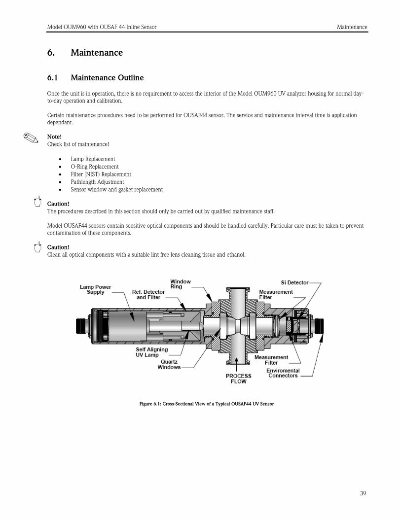
6.1 Maintenance Outline
Once the unit is in operation, there is no requirement to access the interior of the Model OUM960 UV analyzer housing for normal day-
to-day operation and calibration.
Certain maintenance procedures need to be performed for OUSAF44 sensor. The service and maintenance interval time is application
dependant.
Note!
Check list of maintenance!
• Lamp Replacement
• O-Ring Replacement
• Filter (NIST) Replacement
• Pathlength Adjustment
• Sensor window and gasket replacement
Caution!
The procedures described in this section should only be carried out by qualified maintenance staff.
Model OUSAF44 sensors contain sensitive optical components and should be handled carefully. Particular care must be taken to prevent
contamination of these components.
Caution!
Clean all optical components with a suitable lint free lens cleaning tissue and ethanol.
Figure 6.1: Cross-Sectional View of a Typical OUSAF44 UV Sensor

Model OUM960 with OUSAF 44 Inline Sensor Maintenance
40
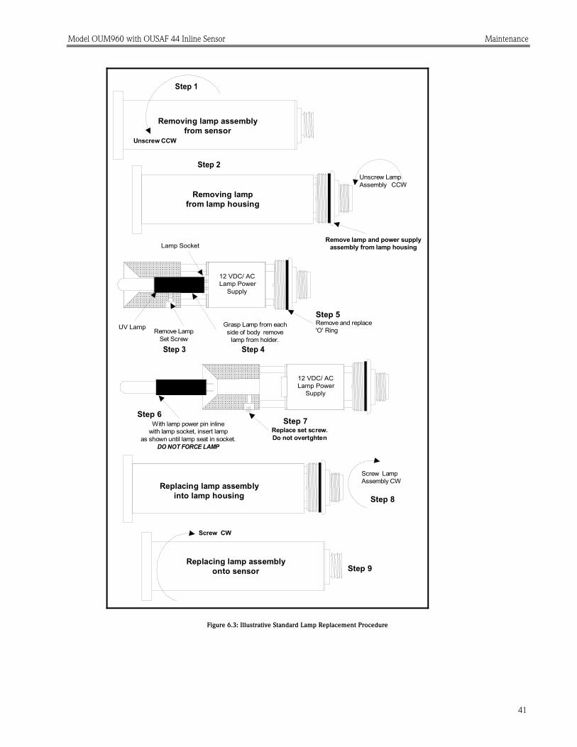
6.2 Mercury Lamp Replacement for OUSAF44
Caution!
Whenever maintenance is performed on the sensor, remove all cables and power to the sensor. Never view the mercury lamp when
powered directly without proper eye protection.
To replace the mercury lamp, proceed as follows (Refer to Figure 6.3: Illustrative lamp replacement procedure):
1. Remove the lamp housing from the sensor by unscrewing the housing CCW.
2. Remove the lamp assembly from the housing by unscrewing the lamp assembly CCW. If tight, use the cable connector body flange as
a “nut” to gain access.
3. Allow the lamp to cool. Loosen and remove the lamp retaining set-screw.
4. Grip the lamp body in the gap between the lamp power supply and the mirrored reflector. Push the lamp towards to reflector until
the lamp is free of the socket. Grip the glass section of the lamp from the end and remove it through the reflector.
5. With the lamp removed, inspect the lamp assembly for any cable fraying or reflector damage. When cleaning any of the optical
surfaces use ethanol and soft, lint free tissue.
Caution!
Clean the new lamp and the mirror with ethanol and lens tissue. After cleaning, do not touch these optical surfaces. When handling the
lamp, use lens tissue or wear talc-free latex gloves.
UV Lamp power pins
Black Anodized Aluminum
Figure 6.2: UV Plug-in Lamp OUSAF44/46 Versions
6. The lamp is replaced by inserting it through the reflector and mating it to it’s socket. Make certain that the lamp pins are in line with
the socket connectors. Gently insert the lamp into the socket making sure that it seats completely.
7. After the lamp has been replaced, reinsert the lamp retaining set screw. This screw is just to hold the lamp in place, do not over
tighten as the lamp could be damaged or broken.
8. The complete lamp and power supply assembly is now refitted into the lamp housing and onto the sensor.
Model OUM960 with OUSAF 44 Inline Sensor Maintenance
41
Remove lamp and power supplyassembly from lamp housing
Unscrew LampAssembly CCW
Step 1
Step 2
Screw LampAssembly CW
Step 8Replacing lamp assembly
into lamp housing
Removing lampfrom lamp housing
Removing lamp assemblyfrom sensor
Replacing lamp assemblyonto sensor
Unscrew CCW
Screw CW
Step 9
Step 6Step 7
12 VDC/ ACLamp Power
Supply
With lamp power pin inlinewith lamp socket, insert lamp
as shown until lamp seat in socket.DO NOT FORCE LAMP
Replace set screw.Do not overtghten
Step 3 Step 4
Remove and replace'O' Ring
Step 5
12 VDC/ ACLamp Power
Supply
UV Lamp
Lamp Socket
Remove LampSet Screw
Grasp Lamp from eachside of body remove
lamp from holder.
Figure 6.3: Illustrative Standard Lamp Replacement Procedure

Model OUM960 with OUSAF 44 Inline Sensor Maintenance
42
6.3 OUSAF44 Measurement Detector/Filter Replacement
The measurement filter is replaced using the following procedure (refer to figure 6.4 for a view of the assembly):
LAMP HOLDER
2-56 X 3/16"
TYPICAL VIEW
INTERFERENCEFILTER
0-ring
Figure 6.4: Reference Detector/Filter Replacement
1. Remove the measurement detector housing from the sensor.
2. Loosen and remove the 4 screws holding the measurement detector back plate onto the back of the measurement detector housing.
Take care to retain all screws, washers and the sealing “O” ring.
3. Withdraw the back plate assembly from the housing.
4. Remove the 2 black anodized screws holding the detector assembly to the back plate and carefully separate, protecting the
interconnecting connecting cable.
5. Remove the 2 screws holding the detector PCB to the back of the filter holder and separate.
6. Remove the two setscrews holding the filters into the holder; turn the filter holder over and drop the filters into your hand.
7. Fit the new filters into the detector/filter holder taking care to ensure that they are installed “shiny” or “mirrored” side towards the
light source and that the correct wavelength value is installed in the correct side. Lightly tighten the retaining setscrews.
8. Clean the detector faces and the filter faces with ethanol and lens tissue. Check and clean all other components as necessary. Install
the detector PCB making sure that the wavelength to channel orientation it is correct.
9. Re-assemble the detector housing in the reverse order, ensuring that the orientation of the detectors is correct to allow use of the
reference rod and that all O-Ring seals are correctly fitted and seated.
10. Replace the measurement detector housing onto the sensor.
11. Calibration of the connected analyzers is required after detector replacement.
Model OUM960 with OUSAF 44 Inline Sensor Maintenance
43
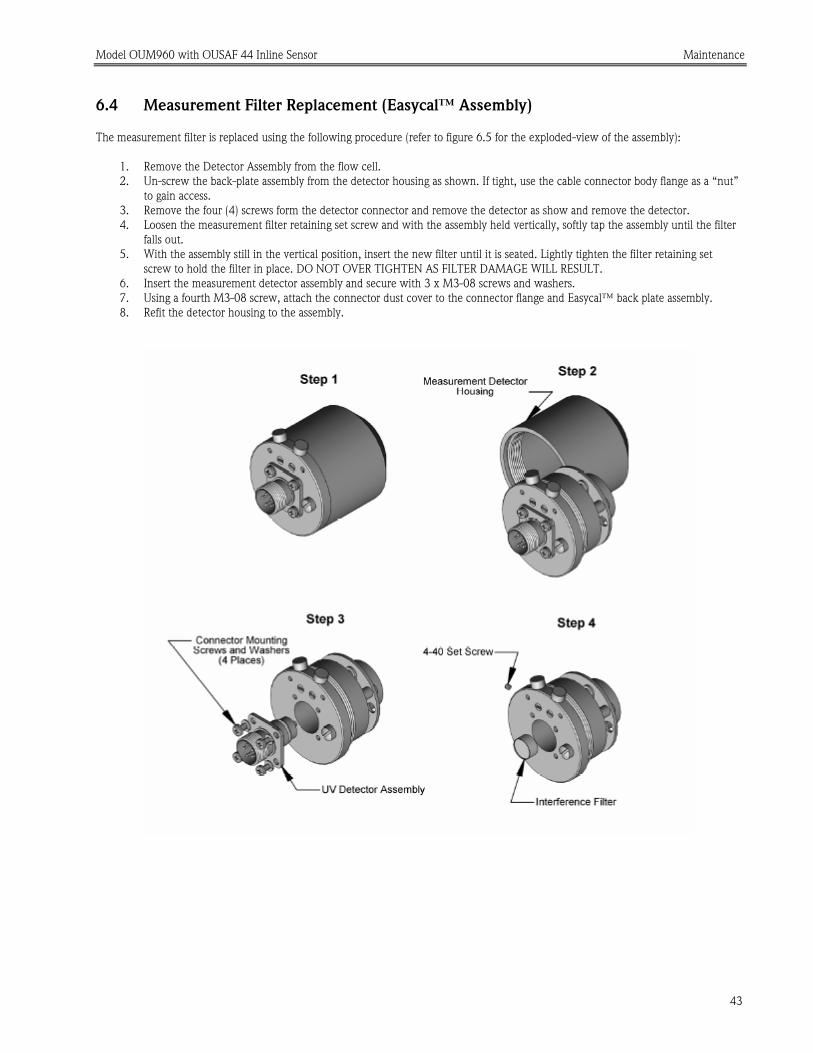
6.4 Measurement Filter Replacement (Easycal™ Assembly)
The measurement filter is replaced using the following procedure (refer to figure 6.5 for the exploded-view of the assembly):
1. Remove the Detector Assembly from the flow cell.
2. Un-screw the back-plate assembly from the detector housing as shown. If tight, use the cable connector body flange as a “nut”
to gain access.
3. Remove the four (4) screws form the detector connector and remove the detector as show and remove the detector.
4. Loosen the measurement filter retaining set screw and with the assembly held vertically, softly tap the assembly until the filter
falls out.
5. With the assembly still in the vertical position, insert the new filter until it is seated. Lightly tighten the filter retaining set
screw to hold the filter in place. DO NOT OVER TIGHTEN AS FILTER DAMAGE WILL RESULT.
6. Insert the measurement detector assembly and secure with 3 x M3-08 screws and washers.
7. Using a fourth M3-08 screw, attach the connector dust cover to the connector flange and Easycal™ back plate assembly.
8. Refit the detector housing to the assembly.

Model OUM960 with OUSAF 44 Inline Sensor Maintenance
44
BACK PLATE
MEASUREMENT FILTERRETAINING PLATE
DETECTORASSEMBLY
FILTERRETAINING
SCREW
MEASUREMENTFILTER
Figure 6.5: Easycal™ Measurement Detector Assembly
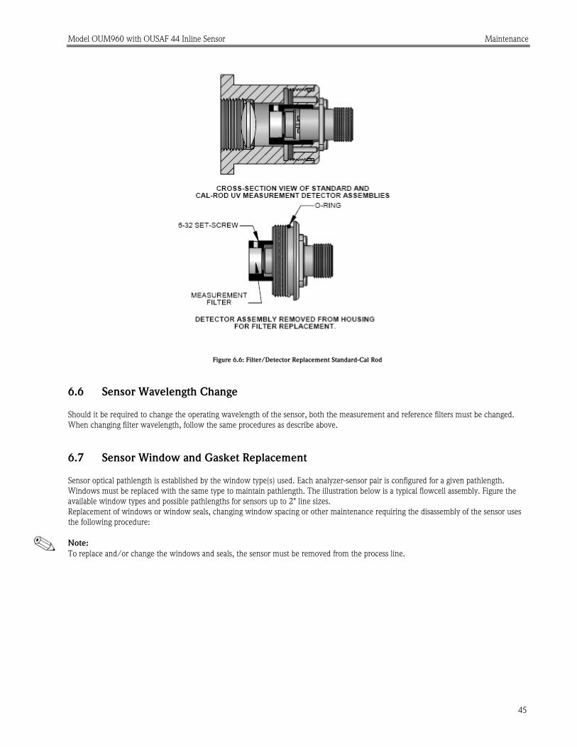
6.5 Measurement Filter Replacement (Standard and Cal Rod Assemblies)
The measurement filter is replaced using the following procedure (refer to figure 6.5 for a cross sectional view of the assembly):
1. Unscrew and remove the outside casing from the Easycal™ Measurement Detector Housing Assembly. If tight, use the cable
connector body flange as a “nut” to gain access.
2. Loosen measurement filter retaining set-screw.
3. Insert measurement filter, mirror side first, into the housing and locate in the filter retaining plate.
4. Tighten the measurement filter retaining set-screw snug against the filter and ensure the filter is held in place.
5. Insert the measurement detector assembly and secure with 3 x M3-08 screws and washers.
6. Using a fourth M3-08 screw, attach the connector dust cover to the connector flange and Easycal™ back plate assembly.
7. Refit the detector housing to the assembly.
Model OUM960 with OUSAF 44 Inline Sensor Maintenance
45
Figure 6.6: Filter/Detector Replacement Standard-Cal Rod
6.6 Sensor Wavelength Change
Should it be required to change the operating wavelength of the sensor, both the measurement and reference filters must be changed.
When changing filter wavelength, follow the same procedures as describe above.
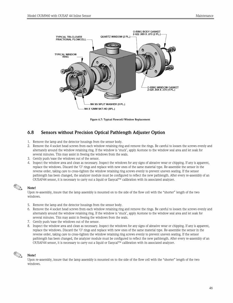
6.7 Sensor Window and Gasket Replacement
Sensor optical pathlength is established by the window type(s) used. Each analyzer-sensor pair is configured for a given pathlength.
Windows must be replaced with the same type to maintain pathlength. The illustration below is a typical flowcell assembly. Figure the
available window types and possible pathlengths for sensors up to 2" line sizes.
Replacement of windows or window seals, changing window spacing or other maintenance requiring the disassembly of the sensor uses
the following procedure:
Note:
To replace and/or change the windows and seals, the sensor must be removed from the process line.
Model OUM960 with OUSAF 44 Inline Sensor Maintenance
46
Figure 6.7: Typical Flowcell/Window Replacement
6.8 Sensors without Precision Optical Pathlength Adjuster Option
1. Remove the lamp and the detector housings from the sensor body.
2. Remove the 4 socket head screws from each window retaining ring and remove the rings. Be careful to loosen the screws evenly and
alternately around the window retaining ring. If the window is ‘stuck’, apply Acetone to the window seal area and let soak for
several minutes. This may assist in freeing the windows from the seals.
3. Gently push/ease the windows out of the sensor.
4. Inspect the window area and clean as necessary. Inspect the windows for any signs of abrasive wear or chipping. If any is apparent,
replace the windows. Discard the 'O' rings and replace with new ones of the same material type. Re-assemble the sensor in the
reverse order, taking care to cross-tighten the window retaining ring screws evenly to prevent uneven seating. If the sensor
pathlength has been changed, the analyzer module must be configured to reflect the new pathlength. After every re-assembly of an
OUSAF44 sensor, it is necessary to carry out a liquid or Easycal™ calibration with its associated analyzer.
Note!
Upon re-assembly, insure that the lamp assembly is mounted on to the side of the flow cell with the “shorter” length of the two
windows.
5. Remove the lamp and the detector housings from the sensor body.
6. Remove the 4 socket head screws from each window retaining ring and remove the rings. Be careful to loosen the screws evenly and
alternately around the window retaining ring. If the window is ‘stuck’, apply Acetone to the window seal area and let soak for
several minutes. This may assist in freeing the windows from the seals.
7. Gently push/ease the windows out of the sensor.
8. Inspect the window area and clean as necessary. Inspect the windows for any signs of abrasive wear or chipping. If any is apparent,
replace the windows. Discard the 'O' rings and replace with new ones of the same material type. Re-assemble the sensor in the
reverse order, taking care to cross-tighten the window retaining ring screws evenly to prevent uneven seating. If the sensor
pathlength has been changed, the analyzer module must be configured to reflect the new pathlength. After every re-assembly of an
OUSAF44 sensor, it is necessary to carry out a liquid or Easycal™ calibration with its associated analyzer.
Note!
Upon re-assembly, insure that the lamp assembly is mounted on to the side of the flow cell with the “shorter” length of the two
windows.

Model OUM960 with OUSAF 44 Inline Sensor Maintenance
47
6.9 Sensors with Precision Optical Pathlength Adjuster Option
Systems fitted with an Easycal™ calibration system may also be fitted with pathlength “adjusters” to allow trimming of the optical
pathlength to the exact distance required for measurement. The precision pathlength adjuster is not required for systems being calibrated
using liquid standards.
Figure 6.8: OUSAF44 Sensor with Precision Pathlength Adjuster Option
1. Remove the lamp and the detector housings from the sensor body.
2. Remove the 4 socket head screws from each window retaining ring and remove the rings. Be careful to loosen the screws evenly and
alternately around the window retaining ring. If the window is ‘stuck’, apply Acetone to the window seal area and let soak for
several minutes. This may assist in freeing the windows from the seals.
3. Gently push/ease the windows out of the sensor.
4. Inspect the window area and clean as necessary. Inspect the windows for any signs of abrasive wear or chipping. If any is apparent,
replace the windows.
5. Assemble window actuators into window rings, adjusting to their widest position (rotated all the way into the window ring). Insert
the locking set-screws into the sides of the window rings, but do not tighten.
6. Install a new “O” seal and window into one side of the flow cell.
7. Place the Thrust Washer into its seat in the actuator ring and install the complete window ring onto the flowcell, taking care to align
the screw holes properly.
8. Install and tighten the four socket head screws to secure the window ring to the flow cell.
9. Repeat the above for the other side.
10. Once both windows are installed and the rings secured, clean and insert the pathlength gauge into the cell down through one of the
tube entries until it is between the window faces.
11. Using the Pathlength Adjusting Tool, narrow the pathlength by carefully screwing in the actuator on each side (in small increments)
until the pathlength gauge just touches both windows. Do not over tighten.
12. Carefully withdraw the pathlength gauge and tighten the locking set-screws to hold the actuator in place.
13. If possible, pressure test assembled flow cell at two times (2X) process pressure. Re-check with pathlength gauge and adjust
pathlength as needed. Pressure testing cycles the compression of the window o-rings and actuator upon assembly. This will
compensate for any initial changes in the pathlength.
Note!
Some window faces may not be parallel to each other. This is normal, especially with fire-polished quartz windows. Take care to ensure
pathlength gauge does not scratch window faces.

Model OUM960 with OUSAF 44 Inline Sensor Maintenance
48
Window Actuator
Window Ring
Install actuatorfor full engagement
Seat Thrust Washerinto Actuator.
Install assembly onto flowcell w/ windowsand process sealing
o-ring in place.
Tighten 4 ea. M4 x 10socket head screws andlock washer onto flowcell
(both sides).
Process Sealing O-RingWindow
Figure 6.9: Assembling the Precision Pathlength Adjustment Rings into the Sensor

Model OUM960 with OUSAF 44 Inline Sensor Maintenance
49
Pathlength Gauge
Pathlength Adjusting Tool
Insert gauge in place. Adjust each side in small increments on alternating sides until gauge just touches windows.
Tighten Locking Set Screwafter pathlength is adjusted.
Figure 6.10: Adjusting Pathlength in the Flow cell

Model OUM960 with OUSAF 44 Inline Sensor Maintenance
50
1mm Pathlength
2mm Pathlength
5mm Pathlength
1cm Pathlength
2cm Pathlength
1cm Pathlength
5mm Pathlength
2mm Pathlength
2cm Pathlength
Window Selection for 1/2" and 3/4"
TC sensors
Window Selection for 1" and 1-1/2"
TC sensors
Window Selection for 2"
TC sensors
Window Type vs. Length
Type A = 14.0mmType B = 19.0mmType C = 24.0mm Type D = 23.0mm Type E = 18.0mmType F = 33.5mm Type G = 09.0mmType H = 31.5mm Type I = 18.5mmType J = 23.5mmType K = 16.5mmType L = 21.5mmType M = 29.0mmType N = 34.0mm
Type E + B
Type E + E
Type A + B
Type A + A
Type B + C
Type D + D
Type B + B
Type A + A Type C + C
UV Quartz Windows
1mm Pathlength
Type D + C
0.5mm Pathlength
Type I + B
0.5mm Pathlength
Type J + C
5mm Pathlengthfor use w/ POPL
Type K + K
5mm Pathlengthfor use w/ POPL
Type L + L
2cm Pathlength
Type G + G
3cm Pathlength
Type G + G
4cm Pathlength
Type A + A
5cm Pathlength
Type G + G
1cm Pathlength
Type M + M
5mm Pathlength
Type H + H
1mm Pathlength
Type F + F
0.5mm Pathlength
Type F + N
3cm Pathlength
Type B + B
Figure 6.11: Window Type vs. Sensor Pathlength

Model OUM960 with OUSAF 44 Inline Sensor Replacement Parts
51
7. Replacement Parts List
7.1 Model OUM960 UV Analyzer
DESCRIPTION Reference No. Part Number
Fuse, AC Input 3.15A GDA Ceramic 1678-0017-00 63006917
Fuse, DC Input 1A MST 1678-1000-00 63006930
Fuse, Relays/Alarm 125mA MSF 1678-0125-00 63006925
7.2 Model OUSAF44 UV Inline Sensor /OUA260 Flow Cell
DESCRIPTION Reference No. Part Number
Replacement Mercury Lamp, Phosphor Coated (276, 280nm) 1415-0150-00 63006614
Replacement Mercury Lamp, Uncoated (254, 295, 302, 313, 365nm) 1415-0160-00 63006615
Reference Detector (Pre 1999 units) 1405-0030-00 63006514
Reference Detector PCB (1999 onward units) A020-0050-00 63009351
Measurement Detector Assembly (TMW) A012-0760-10 63009331
Detector Lens, Quartz 1417-0001-00 63006617
254nm Interference Filter 1410-0254-00 63006537
276nm Interference Filter 1410-0276-00 63006540
280nm Interference Filter Set (1 reference, 1 measurement) A003-0280-00 63009149
295nm Interference Filter 1410-0295-00 63006545
302nm Interference Filter 1410-0302-00 63006547
313nm Interference Filter 1410-0313-00 63006548
365nm Interference Filter 1410-0365-00 63006553
Type 'A' Quartz Window 1420-0140-01 63006635
Type 'B' Quartz Window 1420-0190-03 63006649
Type 'C' Quartz Window 1420-0240-03 63006659
Type 'D' Quartz Window 1420-0230-03 63006654
Type 'E' Quartz Window 1420-0180-03 63006644
Type 'F' Quartz Window 1420-0335-01 63006665
Type 'G' Quartz Window 1420-0090-01 63006630
Type 'H' Quartz Window 1420-0315-01 63006663
Type 'I' Quartz Window 1420-0185-03 63006647
Type 'J' Quartz Window 1420-0235-03 63006657
Type 'K' Quartz Window 1420-0165-03 71000344
Type 'L' Quartz Window 1420-0215-03 63006652
Type 'M' Quartz Window 1420-0290-01 63006662
Type 'N’ Quartz Window 1420-0340-01 63006667
Window Gasket Kit, Viton (USP Class VI) A000-0660-01 63009112
Window Gasket Kit, Kalrez A000-0660-04 63009113
Window Gasket Kit, EPR(EPDM) A000-0660-05 63009114
Window Gasket Kit, PTFE Encapsulated Viton A000-0662-16 63009121
Certified POPL Retrofit Kit for 0.5nm Pathlength A004-4420-00 71000047
Certified POPL Retrofit Kit for 1nm Pathlength A004-4420-01 63011917
Certified POPL Retrofit Kit for 2nm Pathlength A004-4420-02 63009163
Certified POPL Retrofit Kit for 5nm Pathlength A004-4420-05 63009164

Model OUM960 with OUSAF 44 Inline Sensor Technical Information
52
8. Technical Information
8.1 UV Analyzer OUM960
8.1.1 Input
Measured Variable Dual Channel Current from Model OUSAF44 Inline Sensor
Range Up to 5 AU/50 OD dependent upon sensor pathlength and sensor type
Digital Input 4 Channels, dry contact
Keyboard 6 push buttons keyboard
8.1.2 Output
Current Output 2 channel, 4~20mA NUMAR compatible
Resolution 12bit
O1 to PE 500 VDC
O2 to PE 500 VDC
Isolation
O1 to O2 500 VDC
Signal on Lamp Alarm 3.6mA or 21.5mA in case of error
Actual Current
Output Range
3.8mA to 20.5mA
Load 750 ohm Max.
Front Panel Display 4x20 Character LC display
Alarm LED On front Panel, Red LED
General Relay Output 2 Channel, Solid State Relays 250VAC 125mA max.
Relay Operation Above/Below trigger configurable; NO/NC configurable
Relay Delay 0~60 sec configurable
Lamp Alarm Relay 1 Channel, NC
Lamp Power Supply 12V DC, 1.5A Max.
8.1.3 Power Supply
Supply Voltage 85~265 VAC, 24VDC as option
Power Consumption 12 VA Max.
Mains Fuse 3.15 A

Model OUM960 with OUSAF 44 Inline Sensor Technical Information
53
8.1.4 Performance
Sensor Photo Current Input 1mA to 100pA
Linearity 0.3% Max.
Repeatability 0.3% Max.
Accuracy 0.3% Max.
Initial Drifting <0.5% for first 24 hours
8.1.5 Environment
Temperature
(Performance)
0~55°C
Temperature
(Operation)
0~70 55°C
Relative Humidity 95%
Degree of Protection IP 65 (front panel), IP 30 (housing)
8.1.6 Mechanical Construction
Dimensions L x W x D: 102 x 102 x 177 mm
Weight 1.213 kg
Material Aluminum (polyester coating on front panel)
Degree of Protection IP 65 (front panel), IP 30 (housing)
8.2 UV Absorbance Sensor OUSAF44
8.2.1 Input and Output
Measured Input Variable Process UV absorption and optical density
Output Signal Photo detector current (100pA~ 1uA)
8.2.2 Mechanic Construction
Weight 1.225 kg (flow cell not included)
Housing Material Stainless steel 316L

Model OUM960 with OUSAF 44 Inline Sensor Technical Information
54
Figure 8.1: Model OUSAF44 Std. Inline Sensor Dimensions
Connection
Size
A B C D E
1/4" - 3/4" 10.5”
(266.7 mm)
3.75”
(95.3mm)
6.75”
(171.5 mm)
3.25”
(82.5 mm)
1.63”
(41.5 mm)
1" - 1 1/2" 10.88”
(276.2mm)
3.94”
(100.0mm)
6.94”
(176.2mm)
3.25”
(82.5 mm)
1.63”
(41.5 mm)
2" 11.63”
(295.3mm)
4.31”
(109.5mm)
7.31”
(185.7mm)
3.25”
(82.5 mm)
1.63”
(41.5 mm)
Figure 8.2: Model OUSAF44 NIST Inline Sensor Dimensions
Connection
Size
A B C D E
1/4" - 3/4" 10.5”
(266.7 mm)
3.75”
(95.3mm)
6.75”
(171.5 mm)
3.25”
(82.5 mm)
1.63”
(41.5 mm)
1" - 1 1/2" 10.88”
(276.2mm)
3.94”
(100.0mm)
6.94”
(176.2mm)
3.25”
(82.5 mm)
1.63”
(41.5 mm)
2" 11.63”
(295.3mm)
4.31”
(109.5mm)
7.31”
(185.7mm)
3.25”
(82.5 mm)
1.63”
(41.5 mm)

Model OUM960 with OUSAF 44 Inline Sensor Technical Information
55
8.2.3 Environment
Temperature 0~55°C
Temperature
(Process)
0~90 °C Continuous
up to130°C for 2 hours
Relative Humidity 95%
Degree of Protection IP 65
Maximum Pressure in Flow
Cell
33 Bar/500 psi.
100 Bar option available
8.2.4 Power Supply
Supply Voltage 12 VDC
Power Consumption 4 VA continuous
8 VA start up in-rush
8.2.5 Optical Specifications
Line
Size
Pathlengths Available
Wavelengths Available 254, 276, 280, 295, 302, 313, 326 and 365nm
Filters Interference filters, 10 nm BW, stray light .01% maximum.
Detectors UV enhanced Silicon detectors, hermetically sealed.
Lamp Pre-Focused Low pressure Mercury lamp, (2000 hour half life, 3000 hour typical)

Model OUM960 with OUSAF 44 Inline Sensor Ordering Information
56
9. Ordering Information
9.1 UV Analyzer OUM960

Model OUM960 with OUSAF 44 Inline Sensor Ordering Information
57
9.2 UV Absorbance Sensor OUSAF44

Model OUM960 with OUSAF 44 Inline Sensor Ordering Information
58
9.3 Model OUA260 Flow Cell

Model OUM960 with OUSAF 44 Inline Sensor Ordering Information
59
9.4 Model OUK40 UV Sensor Cable Set

Model OUM960 with OUSAF 44 Inline Sensor Warranty
60
WARRANTY
Endress+Hauser Conducta Inc., warrants its products to be free from defects in workmanship and material. Endress+Hauser Conducta
Inc liability is limited to replacing the instrument or any part thereof that is returned by the original purchaser, transportation paid, to the
factory within one (1) year after the date of shipment, provided that Endress+Hauser examination shall disclose that a defect existed
under proper and normal use.
Endress+Hauser Conducta Inc. shall not be liable for consequential or incidental damages.

61

www.endress.com/worldwide