model rp050bmst-s1 respiratory protector … · model rp050bmst-s1 respiratory protector® manual...
TRANSCRIPT

MODEL RP050BMST-S1RESPIRATORY PROTECTOR®
MANUAL
********************************************************************************************WARNING: Do not attempt to operate this equipment without first reading and understanding themanual enclosed with this device. Suitability for use of this device lies solely with user.********************************************************************************************
12/99

CONTENTS
SPECIFICATIONS . . . . . . . . . . . . . . . . . . . . . . . . . . . . . . . . . . . . . . . . . . . . . . . . . . . . . . . . . . 3
GENERAL SAFETY WARNINGS . . . . . . . . . . . . . . . . . . . . . . . . . . . . . . . . . . . . . . . . . . . . . . 4
GENERAL FILTER SYSTEM DESCRIPTION . . . . . . . . . . . . . . . . . . . . . . . . . . . . . . . . . . . . 5
GENERAL OPERATIONS
INTRODUCTION . . . . . . . . . . . . . . . . . . . . . . . . . . . . . . . . . . . . . . . . . . . . . . . . . . . . 7
CUSTOMER AIR SUPPLY . . . . . . . . . . . . . . . . . . . . . . . . . . . . . . . . . . . . . . . . . . . . . . 7
MST RESPIRATORY PROTECTOR INITIAL INSTALLATION AND START-UP . . . . . . . . . . . . . . . . . . . . . . . . . . . . . . . 8
MST RESPIRATORY PROTECTOR GENERAL OPERATION AND MAINTENANCE . . . . . . . . . . . . . . . . . . . . . . . . . . 11
FILTER SET SERVICE INSTRUCTIONS . . . . . . . . . . . . . . . . . . . . . . . . . . . . . . . . . . . . . . 13
RECORD KEEPING . . . . . . . . . . . . . . . . . . . . . . . . . . . . . . . . . . . . . . . . . . . . . . . . . . . . . . . 15
PERFORMANCE CURVES . . . . . . . . . . . . . . . . . . . . . . . . . . . . . . . . . . . . . . . . . . . . . . . . . . 17
PART LIST . . . . . . . . . . . . . . . . . . . . . . . . . . . . . . . . . . . . . . . . . . . . . . . . . . . . . . . . . . . . . . . 19
MATERIAL SAFETY DATA SHEETS
CHARCOAL (THIRD STAGE) . . . . . . . . . . . . . . . . . . . . . . . . . . . . . . . . . . . . . . . . . 24
CATALYST (FOURTH STAGE) . . . . . . . . . . . . . . . . . . . . . . . . . . . . . . . . . . . . . . . . 20

SPECIFICATIONSRESPIRATORY PROTECTOR®
MODEL RP050BMST-S1
INLET PRESSURE (MAX.) 150 PSIG STATIC (10.4bar)
RATED AIR FLOW (MAX.) 50 SCFM (23.6 L/s)
OPERATING PRESSURE 100 PSIG DYNAMIC (6.9bar)
OUTLET PRESSURE RANGE 0-125 PSIG (0-8.6 bar)
OPERATING RELATIVE HUMIDITY 30-100% RH(INLET AIR)
OPERATING TEMPERATURE RANGE 68-150OF (20-65OC)(INLET AIR)
INLET CARBON MONOXIDE CONCENTRATION 40 PPM (VOLUME)*(MAX.)
OUTSIDE DIMENSIONS 24"L x 24"W x 5.75"D(610mm x 610mm x 146mm)
WEIGHT (INCLUDING MONITOR) 27 LBS. (12.3 kg.)
REPLACEMENT FILTER SET FX050
*BASED ON MAXIMUM FLOW CONDITIONS (50 SCFM) FOR 40 HOURS MINIMUMCONTINUOUS PERFORMANCE.

GENERAL SAFETY WARNINGS
WARNING: The MST RESPIRATORY PROTECTOR MODELS:
1) SHOULD NOT be used when the air entering the filtering system is oxygen deficient. The
MST Respiratory Protector® will not increase the oxygen content of the air.
2) SHOULD NOT be used in an Immediately Dangerous to Life and Health Atmosphere
(IDLH) unless it is used in conjunction with a Back-Up Escape system or a supplied air Self-
Contained Breathing Apparatus (SCBA), where applicable.
3) CARBON MONOXIDE MONITOR will alarm if Carbon Monoxide levels exceed
requirements for Grade "D" Breathing Air set fourth by OSHA/CSA. If alarm should sound,
remove respirator or activate SCBA and immediately move to safe breathable atmosphere.
Have the proper qualified personnel examine the equipment and make the appropriate
corrections before using again.
4) SHOULD NOT have air inlet pressure greater than 150 PSIG static (10.4bar). Personal
injury could result.
5) SHOULD NOT have air outlet pressure that exceeds Manufacturers' Respirator/Hose
Assembly pressure requirements. Personal injury could result.
The MST Respiratory Protector® is a Four Stage Purification System designed to remove or reduce
select contaminates including Carbon Monoxide that is found in compressed air lines while
monitoring for carbon monoxide through the MST Monitor. The Respiratory Protector can be
connected directly to shop air from a standard compressed air source to help provide breathing
quality air to face masks, helmets, hoods and other supplied air breathing apparatus.

GENERAL FILTER SYSTEM DESCRIPTION(Refer to Figure No.1)
Air entering the MST Respiratory Protector® at the inlet (A) is usually contaminated with oil, water,dirt, rust, scale, gaseous Hydrocarbons and often deadly Carbon Monoxide. As the air passes throughthe First Stage (B) of the MST Prefilter, particulate matter is trapped and retained down to 0.3microns. The air then enters the Second Stage (C) of the Prefilter which coalesces liquidcontaminates down to 0.75 microns with an efficiency rating of 99.97% (meets UnderwritersLaboratories Specification UL 586 for High Efficiency, Particulate, Air Filter Units). The liquidcontaminates are trapped in the lower chamber of the prefilter and expelled out through theAutomatic Float Drain (D). The Third Stage (E) contains a deep bed of odor absorbing activatedcharcoal which collects various gaseous Hydrocarbons (such as oil vapors, benzene, etc.). The FourthStage (F) contains a low temperature catalyst which converts Carbon Monoxide gas into CarbonDioxide. The unique catalyst also converts or absorbs ozone, Nitric Oxide, Sulfur Dioxide, NitrogenDioxide, Hydrogen Sulfide, Ammonia, Acetaldehyde, Methyl Chloride, Methyl Ethyl Ketone,Acetone and Methyl Alcohol. The air then passes through a one (1) micron filter disc (G) beforeentering the Regulator (H), which is used to adjust the air pressure going to the respirator. A sampleof the filtered air is taken at (I) and passed through the Carbon Monoxide Monitor (J). The CarbonMonoxide Monitor continuously checks the carbon monoxide levels per OSHA/CSA requirementsand digitally displays the amount present in PPM, (parts per million). An audio and visual alarm willalert operators if levels of carbon monoxide exceed OSHA/CSA requirements.
FIGURE NO. 1

MODEL RP050BMST-S1RESPIRATORY PROTECTOR®
FIGURE NO. 2

GENERAL OPERATIONS
********************************************************************************************WARNING: The MST Respiratory Protector should not: 1) be used when the air entering MST's Unit is oxygen deficient. MST's Unit will not increase theoxygen content of the oxygen deficient air.2) be used in an "Immediately Dangerous to Life and Health" atmosphere, (IDLH), unless it is usedin conjunction with a back-up escape system or a supplied air self-contained breathing apparatus,(SCBA), where applicable.********************************************************************************************
MST, Inc. strongly recommends that a complete safety program be instated to ensure that therespiratory air is in compliance with all OSHA/CSA standards and other applicable laws regulating theuse of supplied air respiratory systems. MST, Inc. recommends that the air quality be tested uponinstallation and periodically re-tested to ensure that the minimum requirements for breathing air aremaintained.
MST, Inc. will not assume any liability for accidents or personal injury resulting from the improper useof this equipment. Service on this equipment should only be performed by qualified personnel. Thissystem is to be used only by trained qualified personnel in accordance with a respiratory program asoutlined in OSHA Regulation 29 CFR 1910.134(b).
CUSTOMER AIR SUPPLY(Refer To Figure No. 3)
1) SUPPLIED AIR LINE - Use minimum 3/8" I.D. hose or pipe to MST Unit.2) SUPPLIED AIR LINE PRESSURE - Maximum air pressure at MST Unit's inlet should not
exceed 150 PSIG. As a Safety Back-Up, all MST Units incorporate a pressure relief valverated at 150 PSIG.
3) SUPPLIED INLET AIR TEMPERATURE RANGE - 68 to 150oF (20-65oC).4) SUPPLIED AIR CONDITIONING - May be required ahead of MST's Unit to control:
a) Inlet air temperature.b) Large Volumes of oil/water from entering MST Unit. A coarse oil/water extractor,
(rated at 2-microns abs.), may be required if excessive oil/water conditions are present. Installation of the extractor should be located as close to MST Unit's inlet hook-upas possible. MST, Inc. has coarse oil/water extractors available as an option.
5) AVOID INSTALLING MST UNIT AFTER DESICCANT DRYER - The Desiccant Dryer willproduce extremely dry air, (4% R.H. or less), and MST's fourth stage catalyst requires 30-90%R.H. in the supplied air for the catalyst to work and remove Carbon Monoxide efficiently. Theextremely dry air produced by a Desiccant Dryer will also cause worker discomfort, i.e. dry throat,etc.

MST RESPIRATORY PROTECTOR INITIALINSTALLATION AND START-UP
(Refer To Figure No. 3 and 4)
1) CONNECT CUSTOMER’S PIPE/HOSE TO MST UNIT - Be sure a minimum 3/4" I.D. pipeor hose is used. Purge new air line prior to connecting to MST Unit.
2) NEW FILTER SYSTEM CONDITIONING - Flow supplied air through new filter sets forseveral minutes to condition.
3) POWER MONITOR/CALIBRATE - Supply a dedicated 120 VAC switched outlet for the 120VAC Adapter that comes with unit (adapter will convert the 120 VAC to a 9 VDC output). SeeMST MONITOR MANUAL, Accessories section, for further details. Plug the 120 VAC Adaptercord into the right side of monitor at jack located below the monitor’s battery compartments. Two9-volt batteries are supplied with unit and can be installed in monitor to provide a back-up powersource if the main 120 VAC power source fails or is shut-off by mistake. The batteries will powermonitor continually for 30 - 35 hours. After connecting monitor to power source, turn on and leavewarm-up for (5) minutes. Now check monitor’s circuits/audible-visual alarm system by pressing“OFF/ON TEST” switch up and hold. If monitor OK, the following will occur:
1) Red/Amber LED - will come on steady2) Green LED - will blink, then come on steady3) Audible alarm will sound and the remote alarm jack will be energized.
Monitor’s calibration should be checked now. Refer to MST MONITOR MANUAL.4) CALIBRATION GAS REQUIREMENTS - Zero Gas: Nitrogen, free of ‘CO’. Span Gas: 50 to
150 ppm of ‘CO’ concentration in air. Calibration gas flow to monitor should be 0.5 to 1.5 SCFH(approx. 472 cc/min).
5) REGULATOR/SAMPLE AIR FLOW METER - Needs to be set so proper air sample flow will bemetered to the monitor. The regulator needs to be adjusted for proper air flow to breathing airsystem and then the air flow meter ball set between 0.5 - 1.5 SCFH or in the green boxed area,(depending on style of scale meter has).
6) EXTREME TEMPERATURE CHANGES - Avoid; MST’s monitor best performs at a temperaturerange of 0 - 1050F (-17 to 400C). Always calibrate monitor after it has stabilized in the surroundingair temperature where system is to be used.
7) RESPIRATOR/HOOD/HOSE ASSEMBLY HOOK-UP - Consult Manufacturer’s respiratormanual for the proper air pressure requirements and set regulator(s) at point of attachment (MSTUnit outlet or remote regulated drops). The air should be dynamically flowing throughrespirator/hose assemblies when the air pressure is set. DO NOT EXCEED RESPIRATOR/HOSEASSEMBLY MANUFACTURER’S PRESSURE REQUIREMENTS OR PERSONAL INJURYCOULD RESULT.

MODEL RP050BMST-S1RESPIRATORY PROTECTOR®
FIGURE NO. 3
RESPIRATORY PROTECTOR®MODEL RP050BMST-S1
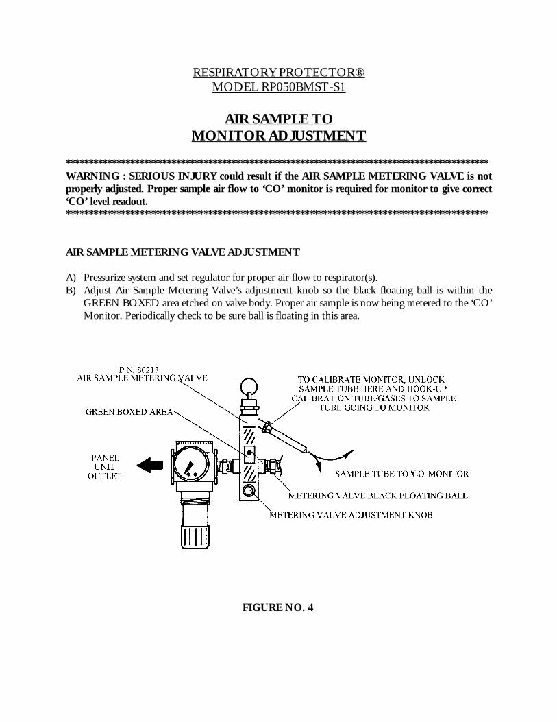
AIR SAMPLE TOMONITOR ADJUSTMENT
********************************************************************************************WARNING : SERIOUS INJURY could result if the AIR SAMPLE METERING VALVE is notproperly adjusted. Proper sample air flow to ‘CO’ monitor is required for monitor to give correct‘CO’ level readout.********************************************************************************************
AIR SAMPLE METERING VALVE ADJUSTMENT
A) Pressurize system and set regulator for proper air flow to respirator(s).B) Adjust Air Sample Metering Valve’s adjustment knob so the black floating ball is within the
GREEN BOXED area etched on valve body. Proper air sample is now being metered to the ‘CO’Monitor. Periodically check to be sure ball is floating in this area.
FIGURE NO. 4

MST RESPIRATORY PROTECTOR®GENERAL OPERATION AND MAINTENANCE
1) MST MONITOR - Utilizes an electrochemical sensor to measure the carbon monoxidecontent of the respirable air. If a problem has developed in the system, the monitor willalarm due to one or more of the following conditions:
a) Monitor is out of calibration. The monitor should be calibrated monthly if usedcontinuously and prior to use if used on a non-continuous basis. Calibrate monitoras outlined in the MST MONITOR MANUAL.
b) If the monitor can be and is calibrated, but the alarm still sounds, the filter cartridgelife is exhausted. Replace all three (3) filter cartridges as outlined in the FILTERREPLACEMENT INSTRUCTIONS, page 13.
c) If the monitor can not be calibrated, the carbon monoxide sensor may require replacement. See MST MONITOR MANUAL for replacement instructions and othertroubleshooting information. The MST MONITOR has one (1) year warranty. Allwarranty work must be performed at factory.
d) If the monitor was calibrated in a surrounding temperature other than where thesystem was being used and the temperature difference was 36oF (20oC) or greater, themonitor may give a false alarm due to its characteristics. Always calibrate the monitor in the temperature conditions where the monitor is to be used in. Monitorbest performs at temperature range of 0 to 105oF (-17 to 40oC).
e) ‘RF’ signals causing interference to monitor through Remote Alarm Options and/orOptional Power Adapter cords. Contact factory if this is occurring.
2) MST MONITOR - Alarms should be checked prior to use.3) MST MONITOR - Power supply is (2) 9-volt transistor - type batteries, (unless optional power
supply used). The batteries will power the monitor continuously for approximately (30-35) hours.When the batteries output fall below (7.3) volts, the Amber LED "Low Battery" light will comeon, indicating the batteries require replacement. When installing the new batteries into the batteryholders, review polarity position marked inside holders and install batteries accordingly.
4) MST MONITOR - Flow of the air sample to monitor should be checked periodically to ensuresample air flow meter is not clogged. This situation normally occurs when customers' supplied airhas excessive liquids in it and the filters in the MST unit are not routinely changed. Periodicallycheck the regulator/air flow meter for proper setting/location of air flow meter floating ball andgeneral appearance (presence of excessive oil, water).
5) MST RESPIRATORY PROTECTOR® SYSTEM - Filters should be replaced monthly unlessthe air quality conditions warrant more or less frequent replacement. Replace all (5) filtercartridges if:
a) The "CO" monitor alarms (fourth stage catalyst is used up).b) The operator detects a petroleum smell and or taste in his purified air (third stage
charcoal is used up).

NOTE: If the supplied air entering MST's unit has high volumes of liquids in it, the filter set life maybe greatly reduced. See CUSTOMER AIR SUPPLY, page 7, for corrective measures to take.6) MST RESPIRATORY PROTECTOR® SYSTEM - New filter set:
a) Has an indefinate shelf life, but should be stored in a cool/dry storage area.b) When first installed in MST's unit the filters should be conditioned by flowing the
customer's supplied air through system for several minutes.
NOTE: If MST's unit is not to be used for an extended period of time, before storing, check3rd and 4th stage filters for presence of liquid/moisture. If moisture present, dry system andreplace all filters. Also, if moisture present, consider changing filter set more frequent andor installing MST's OPTIONAL PREFILTER prior to MST's system hook-up.

FILTER SETSERVICE INSTRUCTIONS
(Refer To Figure No. 5)
********************************************************************************************WARNING: Always turn off air supply and bleed air pressure before disassembling unit orSERIOUS INJURY COULD RESULT.********************************************************************************************
MST, Inc. recommends replacing all three (3) filter cartridges after one (1) month of use unlessconditions warrant more or less frequent replacement. To replace the filter cartridges in theRESPIRATORY PROTECTOR® follow these steps:
1) PREFILTER FIRST/SECOND DUAL STAGE ELEMENT REPLACEMENTa) First unlock tube locking collar and then pull Drain Tube 1 down through case. Then
unscrew Prefilter Bowl Assembly 2 , clean in mild soap and water and blow dry withlow pressure air.
b) Remove Dual Stage Element 3 by unscrewing End Cap Retaining Nut 4 .c) Inspect the Prefilter Manifold 5 for dirt/contaminates and clean as required. Inspect
O-Ring 6 for cuts, etc. and replace if required.d) Install new Dual Stage Element and Tighten End Cap Retaining Nut. Be sure
Element is seated squarely on Manifold boss and End Cap.e) Apply light film of petroleum jelly on Bowl's beveled edge to provide good seal
between Bowl and O-Ring. HAND TIGHTEN ONLY.f) Guide Drain Tube back through hole in case bottom and lock into tube locking collar.g) Dispose of used Dual Stage Element according to local, state and federal regulations.
2) THIRD/FOURTH STAGE CARTRIDGE REPLACEMENTa) Loosen Bracket Bolt 7 from Bracket 8, (do not remove).b) Loosen the five Manifold Bolts 9 and remove the front two Bolts. Now slide out
the Third 10 and Fourth 11 Stage Aluminum Tube Assemblies. c) Remove the End Cap 12 from Third Stage Aluminum Tube Assembly and slide old
Third Stage Filter Cartridge 13 out of aluminum tube. Clean aluminum tube in mildsoap and water, dry and install new Third Stage Filter Cartridge. Be sure the FlowDirection Arrow on Third Stage Filter Cartridge is pointing down. Remove EndSealing Label 14 and install new End Cap.
d) Follow same procedure for the Fourth Stage Filter Cartridge 15 replacement as in step(C). Be sure the Flow Direction Arrow on Fourth Stage Filter Cartridge is pointingup. Also be sure to remove End Sealing Label before installing new End Cap.
e) Now slide the Third and Fourth Stage Aluminum Tube Assemblies back in place andinstall the front two Manifold Bolts.
f) Tighten Manifold Bolts in sequence from center outward to 100 inch-pounds (1.15Kg-M). Repeat sequence and re-torque bolts to 250 inch-pounds (2.88 Kg-M).
g) Tighten Bracket Bolt 7 against Bracket 8 .h) Dispose of used cartridges according to local, state and federal regulations.

3) FINAL CHECK AND CALIBRATIONa) Pressurize system and check for leaks.b) Flush system with compressed air for several minutes.c) Calibrate Carbon Monoxide Monitor as outlined in MST MONITOR MANUAL.
FIGURE NO. 5

RECORD KEEPING
Record all periodical air quality checks, monitor calibration date, filter cartridge change intervals andany other service performed on the MST RESPIRATORY PROTECTOR®.
MST INC. SHALL NOT BE LIABLE FOR ANY INJURY, LOSS OR DAMAGE, (DIRECTOR CONSEQUENTIAL), ARISING OUT OF THE USE OF OR THE INABILITY TO USETHIS PRODUCT, BEYOND THE REPLACEMENT OF DEFECTIVE MATERIALS ORWORKMANSHIP. USER OF SUPPLIED AIR RESPIRATORS SHOULD EVALUATETHEIR OWN PARTICULAR APPLICATION AND PERFORM THEIR OWN TESTS FORAIR QUALITY TO DETERMINE THE SUITABILITY FOR USE OF THIS PRODUCT.
For further information, or questions about service or maintenance care of this unit, contact yourlocal distributor or MST @ (800) 542-6646.

MST, INC.SERVICE RECORD
RESPIRATORY PROTECTOR®
MODEL RP050BMST-S1
DATE OF SERVICE SERVICE PERFORMED


MODEL RP050BMST-S1RESPIRATORY PROTECTOR
1 80106, (1), 1/2" BALL VALVE 14 12021, (5), MANIFOLD WASHERS
2 S608-006, (2), HEX NIPPLE -1/2" x 3/8" 15 S608-005, (2), HEX NIPPLE - 3/8"
3 8009001, (1), PREFILTER-50 SCFM 16 80098, (1), CROSS - 3/8"
4 80051, (1), TUBE LOCKING COLLAR 17 S638-007, (2), 3/8" X 1/4" RD. BUSHING
5 S710-005, (1), DRAIN TUBE 18 80014, (1),PR VALVE, 150 PSI
6 80001, (1), BLUE BASE 19 S623-003, (1), 3/8" x 90O ST. ELBOW
7 80005, (1), A1 TUBE THIRD STAGE 20 S608-002, (1), 1/8" x 1/4" HEX NIPPLE
8 80005, (1), AL TUBE FOURTH STAGE 21 80213, (1), SAMPLING VALVE
9 80114, (1) BASE BRACKET 22 80261, (1), TUBE LOCK COLLAR x 90O
10 80078, (1), BLUE MANIFOLD 23 80076, (1), PRESSURE GAUGE, 0-160
11 80009, (1), MANIFOLD BRACKET 24 80075, (1), REGULATOR
12 S006-148, (3), BRACKET BOLTS 25 80339, (1), MONITOR BRACKET
13 S011-040, (5), MANIFOLD BOLTS 26 8012701, (1), MST "CO" MONITOR