model simulation in rational software architect: sequence ... · benefit. it might also be a good...
TRANSCRIPT
Model Simulation in Rational Software Architect: Sequence Diagram Simulation
Anders EkSenior Manager – Tau Product DevelopmentIBM
In this article we will investigate how to use simulation to explore UML models where sequencediagrams are used as the main scenario description technique. We will go through all stepsnecessary to design this style of UML models to get the most out of the simulation featuresavailable in Rational Software Architect.
We will cover four different aspects:
- How to create a sequence diagram based UML model to describe a set of interactingcomponents.
- How to run a simulation session for sequence diagrams, focusing on animating topologydiagrams.
- How the different sequence diagram symbols will affect a simulation session.- Where to find more information about the simulation feature in Rational Software
Architect.
No previous knowledge is necessary even if some idea of UML and topology modeling is abenefit. It might also be a good idea to read the document ”Model Simulation in RationalSoftware Architect: Getting Started” first, since this covers some general aspects of how to getstarted using the simulation capabilities in Rational Software Architect.
Note that most of the features we will go through refer to news in version 8 and are not availablein previous versions of Rational Software Architect.
Model Simulation in Rational Software Architect: Sequence Diagram Simulation© Copyright IBM Corporation 2010. All rights reserved.
Creating a Sequence Diagram based UML ModelSequence diagrams are used to show how different parts of an application work together toaccomplish some specific use case or scenario. They are most useful if we have a fairly largeapplication that needs several or many interacting components to be successfully implemented.From a high-level point of view the different steps we need to go through in the design andimplementation of this kind of application are:
1. Find out what users we have and what they want to accomplish.2. Detail the scenarios that the users will need when interacting with the system.3. Find out what components we need in our implementation of the scenarios.4. Describe the interaction among the components that will satisfy the scenarios5. Design, implement and deploy the components
The sequence diagrams fit mainly in step 4 above, where the goal is to describe the interactionsamong the components.
Since this article will focus on sequence diagram aspects of life we will happily skip the first twosteps and completely ignore the design and implement parts of the last. This is of course slightlyunrealistic, but still useful to focus on what we want to achieve: An understanding of how todesign and simulate the sequence diagram parts of a UML model.
The example we will look at in the article is one aspect of a very simple distributed application,were a document editing software is used by end-users and a server based solution is used tosynchronise different contributions. There are many possible end-user scenarios that are relevantin this context:
- Synchronising a document being edited locally- Browsing the server for available documents- Retrieving a document from the server for editing- …
We will however focus on the first of these, the synchronisation of a document being editedlocally.
We will also assume that we need three different components, one that runs on the end-userlaptops, one that runs the business logic on a server and one database component to store thedocument details.
So, let’s get started modeling this in Rational Software Architect. The first step is to create a newproject. This is done using the File->New->Project command. For the examples we will use theModeling->UML Project wizard and the General->Blank Package template. We’ll use the name“DocumentSynchApp” for the project and “DocumentSynchPkg” as the package name in thisarticle.
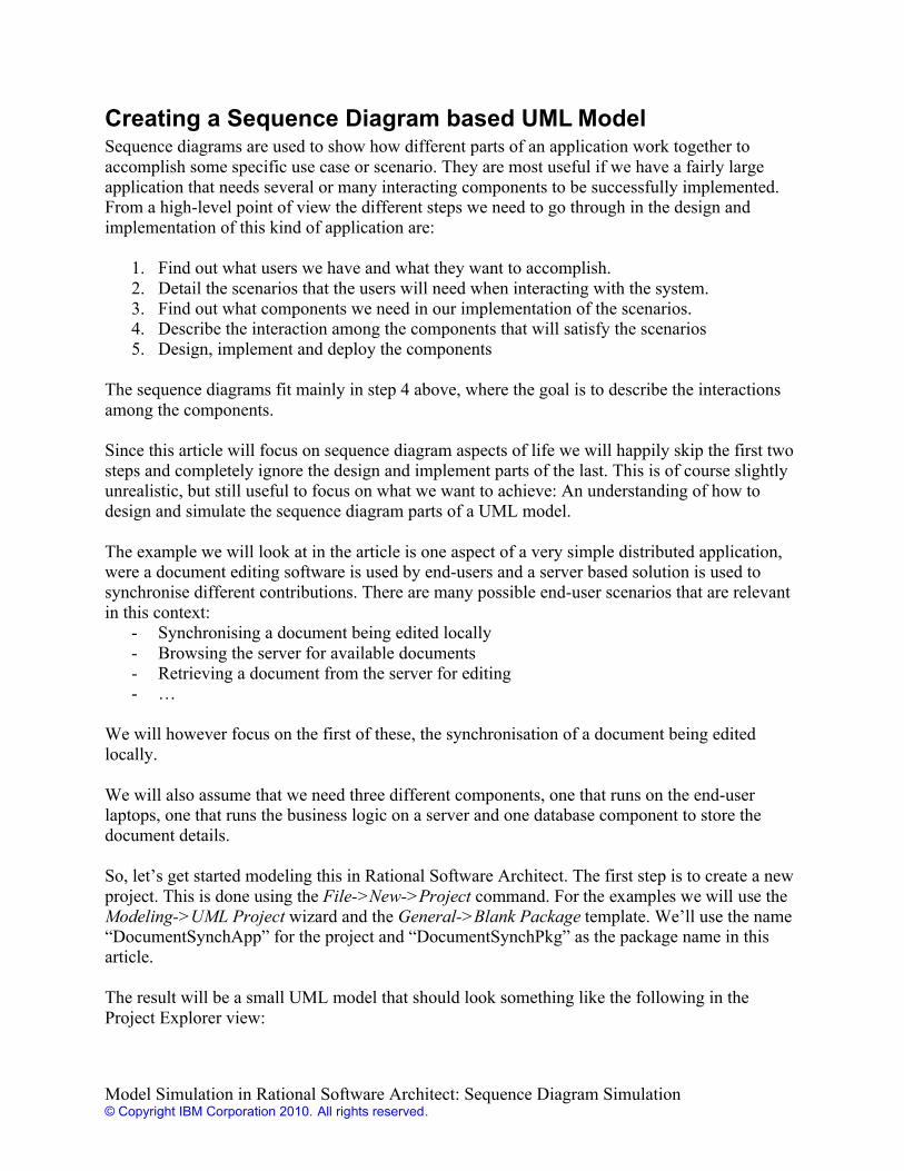
The result will be a small UML model that should look something like the following in theProject Explorer view:
Model Simulation in Rational Software Architect: Sequence Diagram Simulation© Copyright IBM Corporation 2010. All rights reserved.
Since we will ignore the use case analysis that in a real project would have been the first step, wewill dive directly into defining the components we want to have. The easiest way to do this is touse the “Main” diagram what was automatically generated for us. If we open this we can see thatthe palette to the right of the diagram contains a section called “Components” that fits nicely withour needs.
We create three components in the diagram to represent our three application components.
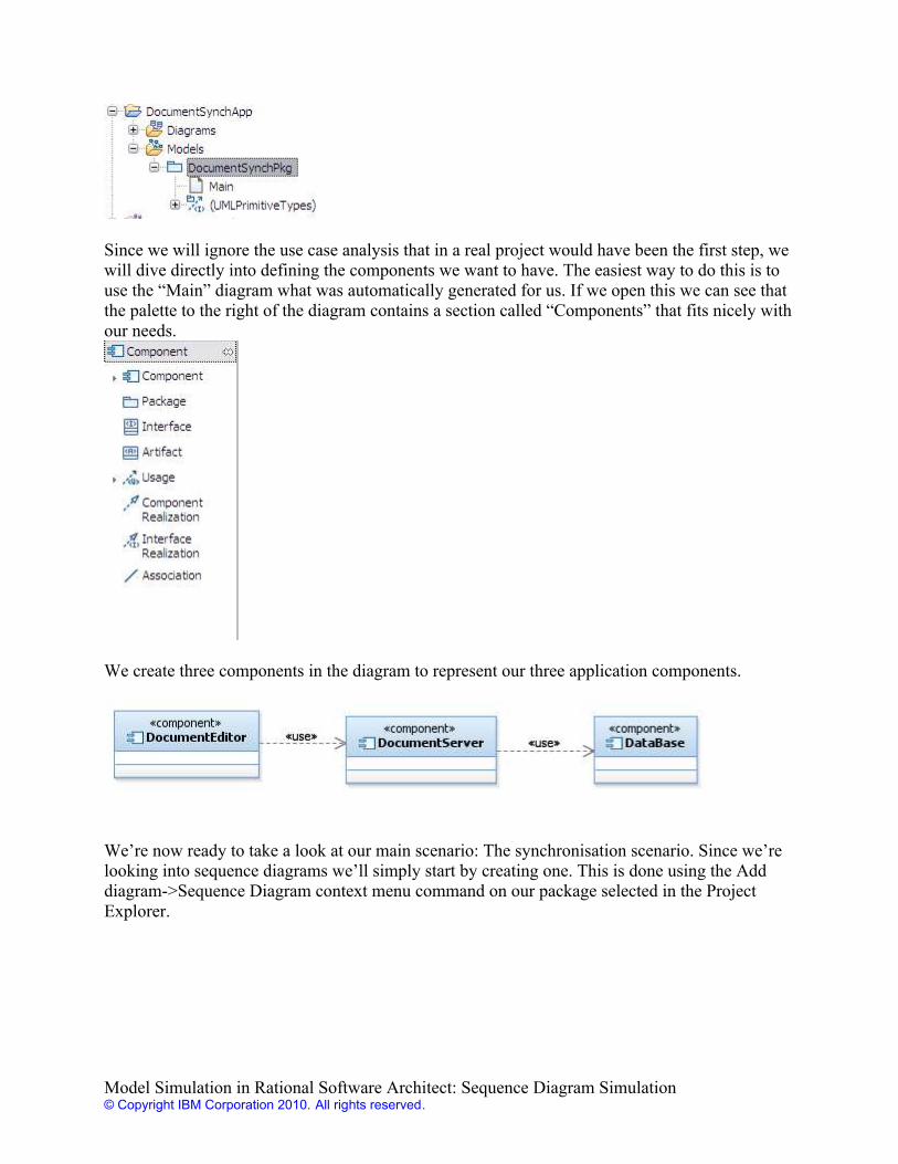
We’re now ready to take a look at our main scenario: The synchronisation scenario. Since we’relooking into sequence diagrams we’ll simply start by creating one. This is done using the Adddiagram->Sequence Diagram context menu command on our package selected in the ProjectExplorer.
Model Simulation in Rational Software Architect: Sequence Diagram Simulation© Copyright IBM Corporation 2010. All rights reserved.
Notice that what we get from this command is actually not only the empty sequence diagram thatwill pop up on our screen, but also a few other elements as we can see in the Project Explorer.
A collaboration is a convenient container for a set of related sequence diagrams, and aninteraction is the container for all elements we will create in each diagram. Let us start byrenaming these to something more appropriate, “DocumentSynchScenarios” for the collaborationand “Synch”/”SynchSD” for the activity/activity diagram.
After renaming to suitable names we have a more understandable Project Explorer hierarchy forour collaboration.
Now let us edit the sequence diagram and add a (very) simple message exchange. We start byadding three lifelines by dragging the components from the Project Explorer to the sequencediagram.
Model Simulation in Rational Software Architect: Sequence Diagram Simulation© Copyright IBM Corporation 2010. All rights reserved.
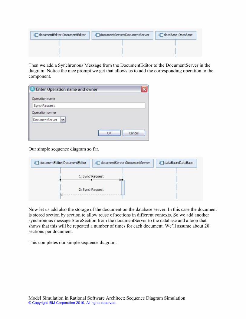
Then we add a Synchronous Message from the DocumentEditor to the DocumentServer in thediagram. Notice the nice prompt we get that allows us to add the corresponding operation to thecomponent.
Our simple sequence diagram so far.
Now let us add also the storage of the document on the database server. In this case the documentis stored section by section to allow reuse of sections in different contexts. So we add anothersynchronous message StoreSection from the documentServer to the database and a loop thatshows that this will be repeated a number of times for each document. We’ll assume about 20sections per document.
This completes our simple sequence diagram:
Model Simulation in Rational Software Architect: Sequence Diagram Simulation© Copyright IBM Corporation 2010. All rights reserved.
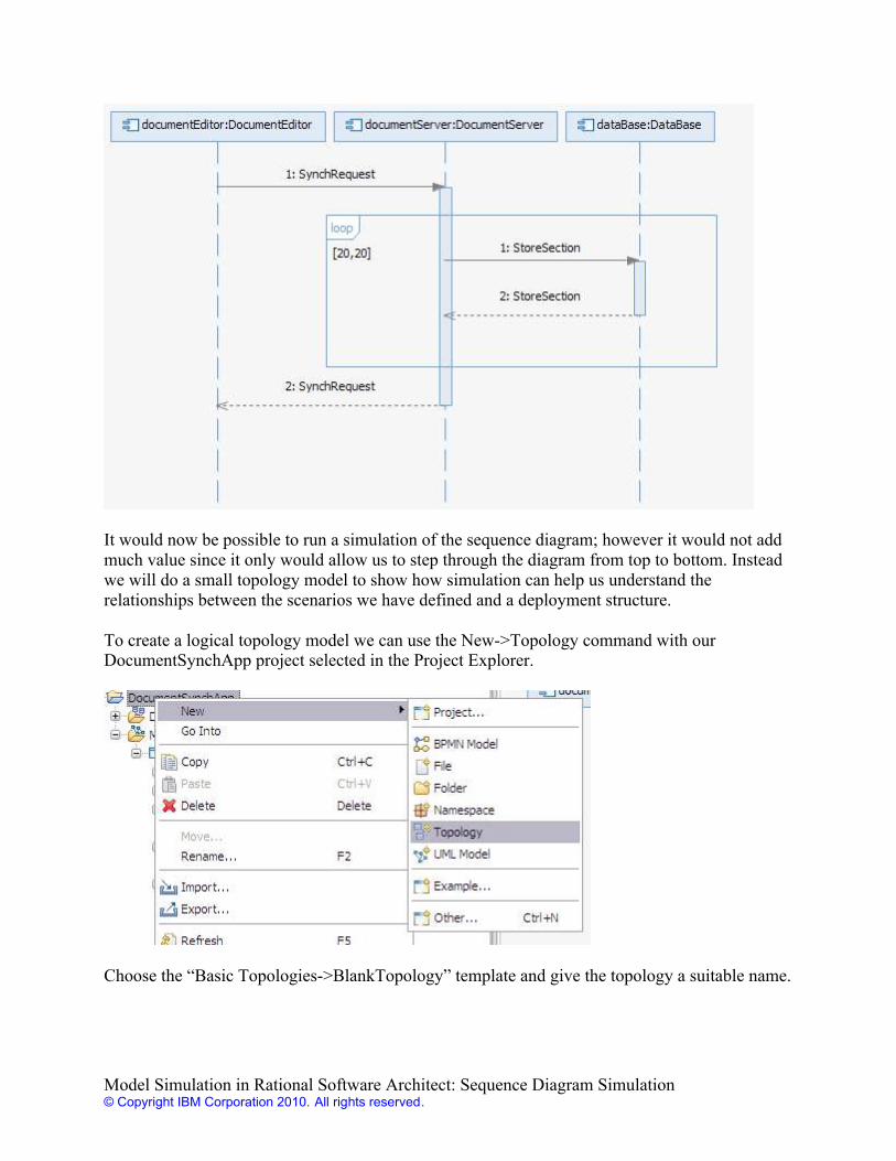
It would now be possible to run a simulation of the sequence diagram; however it would not addmuch value since it only would allow us to step through the diagram from top to bottom. Insteadwe will do a small topology model to show how simulation can help us understand therelationships between the scenarios we have defined and a deployment structure.
To create a logical topology model we can use the New->Topology command with ourDocumentSynchApp project selected in the Project Explorer.
Choose the “Basic Topologies->BlankTopology” template and give the topology a suitable name.
Model Simulation in Rational Software Architect: Sequence Diagram Simulation© Copyright IBM Corporation 2010. All rights reserved.
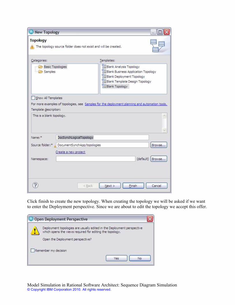
Click finish to create the new topology. When creating the topology we will be asked if we wantto enter the Deployment perspective. Since we are about to edit the topology we accept this offer.
Model Simulation in Rational Software Architect: Sequence Diagram Simulation© Copyright IBM Corporation 2010. All rights reserved.
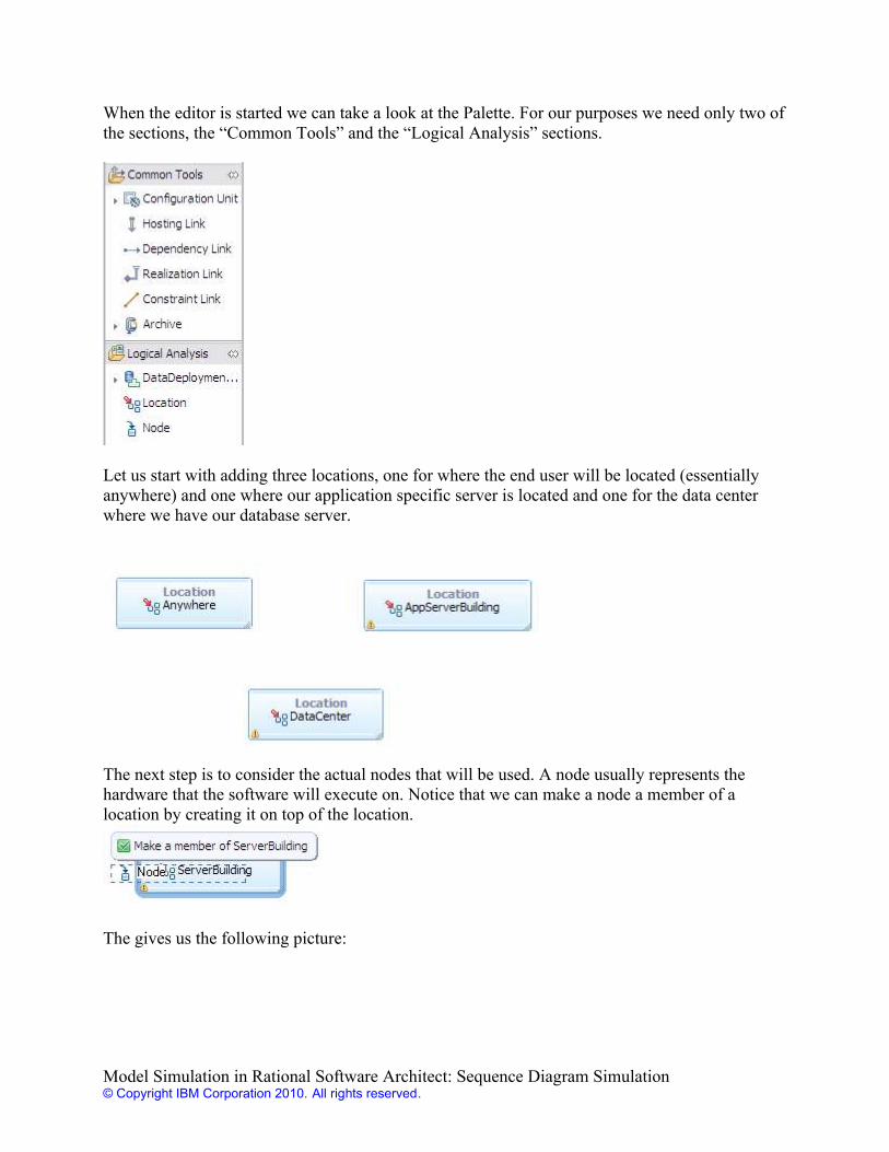
When the editor is started we can take a look at the Palette. For our purposes we need only two ofthe sections, the “Common Tools” and the “Logical Analysis” sections.
Let us start with adding three locations, one for where the end user will be located (essentiallyanywhere) and one where our application specific server is located and one for the data centerwhere we have our database server.
The next step is to consider the actual nodes that will be used. A node usually represents thehardware that the software will execute on. Notice that we can make a node a member of alocation by creating it on top of the location.
The gives us the following picture:
Model Simulation in Rational Software Architect: Sequence Diagram Simulation© Copyright IBM Corporation 2010. All rights reserved.
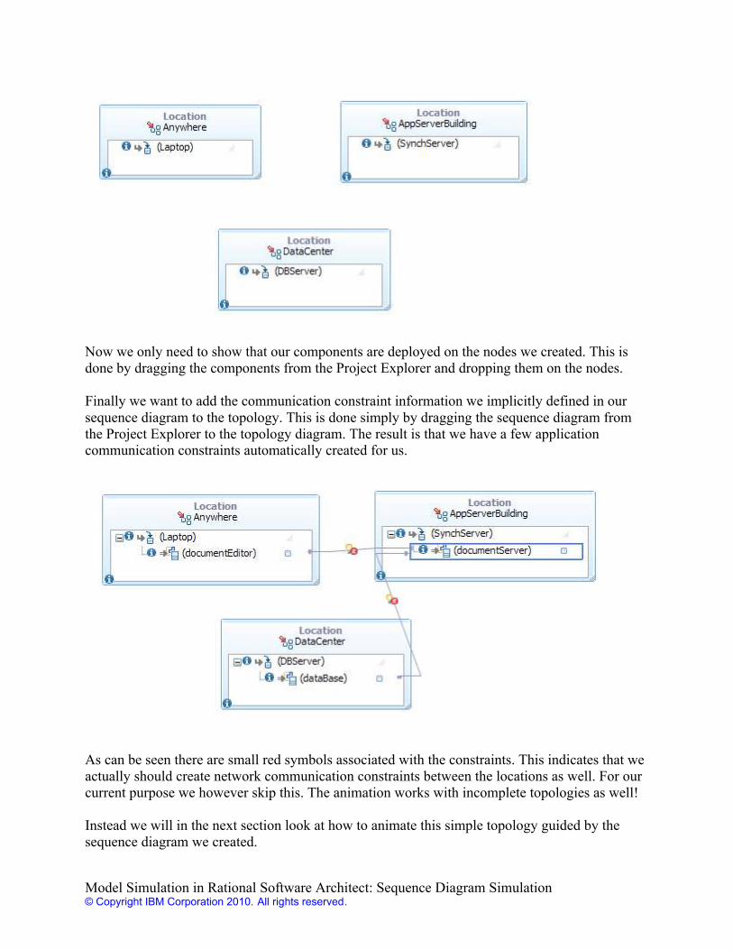
Now we only need to show that our components are deployed on the nodes we created. This isdone by dragging the components from the Project Explorer and dropping them on the nodes.
Finally we want to add the communication constraint information we implicitly defined in oursequence diagram to the topology. This is done simply by dragging the sequence diagram fromthe Project Explorer to the topology diagram. The result is that we have a few applicationcommunication constraints automatically created for us.
As can be seen there are small red symbols associated with the constraints. This indicates that weactually should create network communication constraints between the locations as well. For ourcurrent purpose we however skip this. The animation works with incomplete topologies as well!
Instead we will in the next section look at how to animate this simple topology guided by thesequence diagram we created.
Model Simulation in Rational Software Architect: Sequence Diagram Simulation© Copyright IBM Corporation 2010. All rights reserved.
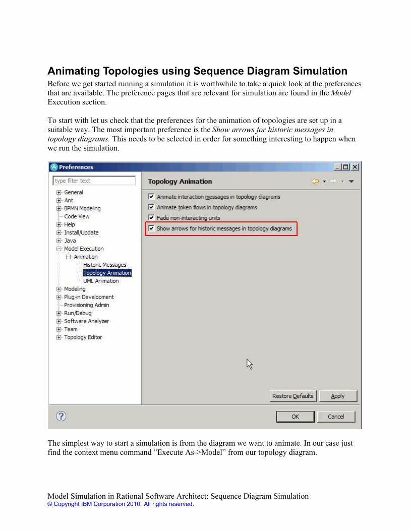
Animating Topologies using Sequence Diagram SimulationBefore we get started running a simulation it is worthwhile to take a quick look at the preferencesthat are available. The preference pages that are relevant for simulation are found in the ModelExecution section.
To start with let us check that the preferences for the animation of topologies are set up in asuitable way. The most important preference is the Show arrows for historic messages intopology diagrams. This needs to be selected in order for something interesting to happen whenwe run the simulation.
The simplest way to start a simulation is from the diagram we want to animate. In our case justfind the context menu command “Execute As->Model” from our topology diagram.
Model Simulation in Rational Software Architect: Sequence Diagram Simulation© Copyright IBM Corporation 2010. All rights reserved.
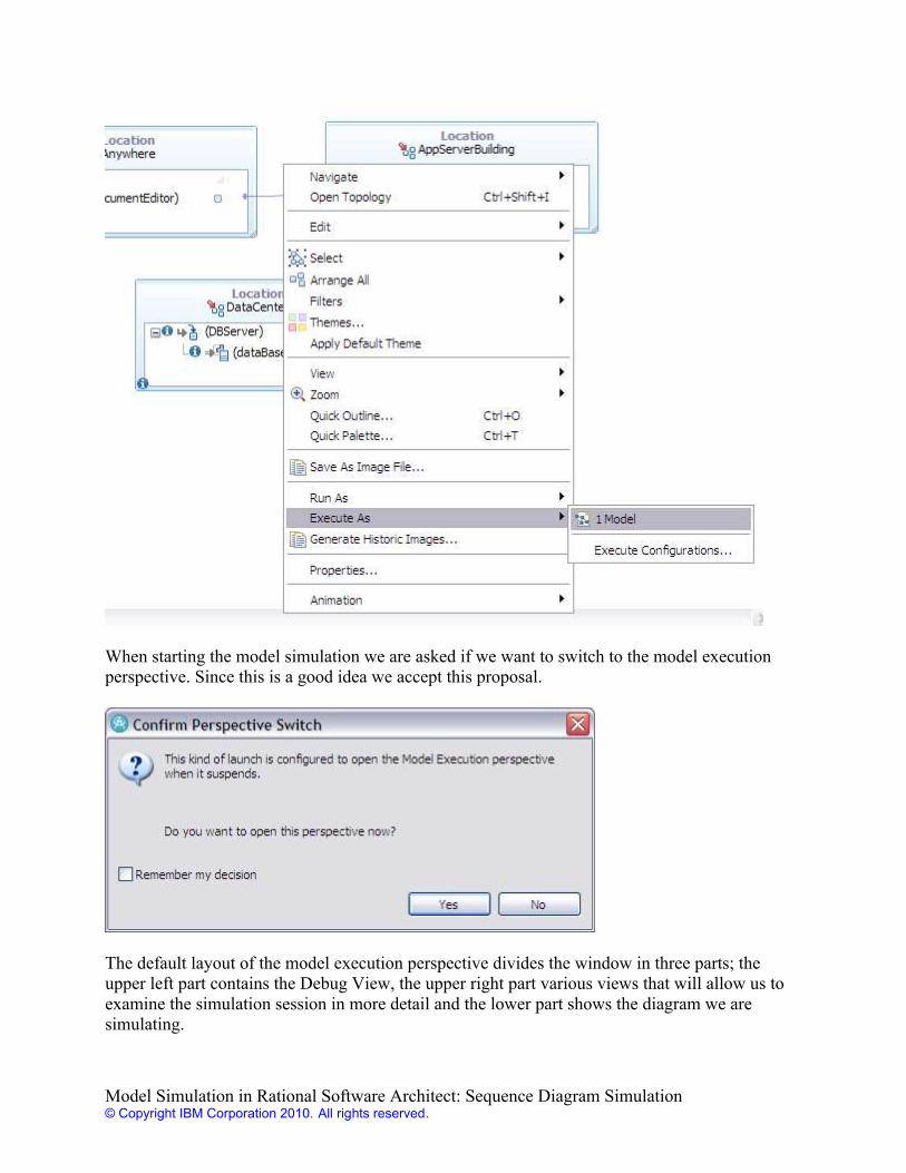
When starting the model simulation we are asked if we want to switch to the model executionperspective. Since this is a good idea we accept this proposal.
The default layout of the model execution perspective divides the window in three parts; theupper left part contains the Debug View, the upper right part various views that will allow us toexamine the simulation session in more detail and the lower part shows the diagram we aresimulating.
Model Simulation in Rational Software Architect: Sequence Diagram Simulation© Copyright IBM Corporation 2010. All rights reserved.
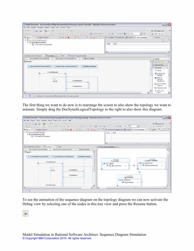
The first thing we want to do now is to rearrange the screen to also show the topology we want toanimate. Simply drag the DocSynchLogicalTopology to the right to also show this diagram.
To see the animation of the sequence diagram on the topology diagram we can now activate theDebug view by selecting one of the nodes in this tree view and press the Resume button.
Model Simulation in Rational Software Architect: Sequence Diagram Simulation© Copyright IBM Corporation 2010. All rights reserved.
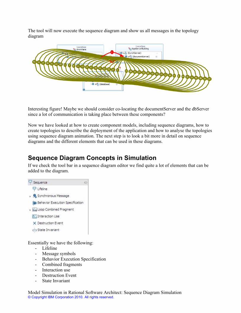
The tool will now execute the sequence diagram and show us all messages in the topologydiagram
Interesting figure! Maybe we should consider co-locating the documentServer and the dbServersince a lot of communication is taking place between these components?
Now we have looked at how to create component models, including sequence diagrams, how tocreate topologies to describe the deployment of the application and how to analyse the topologiesusing sequence diagram animation. The next step is to look a bit more in detail on sequencediagrams and the different elements that can be used in these diagrams.
Sequence Diagram Concepts in SimulationIf we check the tool bar in a sequence diagram editor we find quite a lot of elements that can beadded to the diagram.
Essentially we have the following:- Lifeline- Message symbols- Behavior Execution Specification- Combined fragments- Interaction use- Destruction Event- State Invariant
Model Simulation in Rational Software Architect: Sequence Diagram Simulation© Copyright IBM Corporation 2010. All rights reserved.
We will now go through these elements and look at how they are used in a simulation context.
LifelineLifelines represent the instances that we want to describe in the sequence diagram. A lifeline ismost easily defined using drag-and-drop from the Project Explorer. The first time a component(or class of something similar) is visualised in the sequence diagrams of a collaboration we dragthe component itself to the diagram. As we saw above we then automatically get not only alifeline but also a collaboration local representation of the component (an attribute in UMLterminology).
In the example above we got three attributes in the collaboration we created:
If we want to reuse the same component again in another sequence diagram in the samecollaboration it is easiest to drag the attribute and drop it onto the sequence diagram.
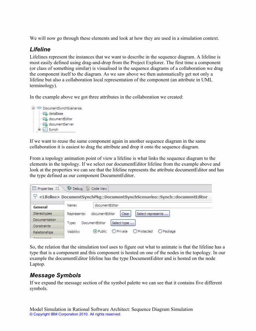
From a topology animation point of view a lifeline is what links the sequence diagram to theelements in the topology. If we select our documentEditor lifeline from the example above andlook at the properties we can see that the lifeline represents the attribute documentEditor and hasthe type defined as our component DocumentEditor.
So, the relation that the simulation tool uses to figure out what to animate is that the lifeline has atype that is a component and this component is hosted on one of the nodes in the topology. In ourexample the documentEditor lifeline has the type DocumentEditor and is hosted on the nodeLaptop.
Message SymbolsIf we expand the message section of the symbol palette we can see that it contains five differentsymbols.
Model Simulation in Rational Software Architect: Sequence Diagram Simulation© Copyright IBM Corporation 2010. All rights reserved.
As we can see these symbols are used to show how the objects represented by the differentlifelines communicate either using operation calls or signals. The difference between an operationbased modeling approach and a signal based approach is not huge from a modeling point of viewand the choice can sometimes seem arbitrary in an analysis model. In most situations bothapproaches work nicely from a modeling point of view. However signals are typically used toprovide a more data or document centric approach and operations an approach that focuses moreon capabilities or functions.
From a topology animation point of view all of the message symbols will correspond to arrows ina topology diagram. The arrows are however only shown if there is a communication constraintline in the topology that matches the source and target of the message in the lifeline.
The details will however be slightly different for each symbol.
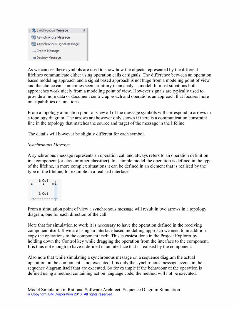
Synchronous Message
A synchronous message represents an operation call and always refers to an operation definitionin a component (or class or other classifier). In a simple model the operation is defined in the typeof the lifeline, in more complex situations it can be defined in an element that is realised by thetype of the lifeline, for example in a realised interface.
From a simulation point of view a synchronous message will result in two arrows in a topologydiagram, one for each direction of the call.
Note that for simulation to work it is necessary to have the operation defined in the receivingcomponent itself. If we are using an interface based modelling approach we need to in additioncopy the operations to the component itself. This is easiest done in the Project Explorer byholding down the Control key while dragging the operation from the interface to the component.It is thus not enough to have it defined in an interface that is realised by the component.
Also note that while simulating a synchronous message on a sequence diagram the actualoperation on the component is not executed. It is only the synchronous message events in thesequence diagram itself that are executed. So for example if the behaviour of the operation isdefined using a method containing action language code, the method will not be executed.
Model Simulation in Rational Software Architect: Sequence Diagram Simulation© Copyright IBM Corporation 2010. All rights reserved.
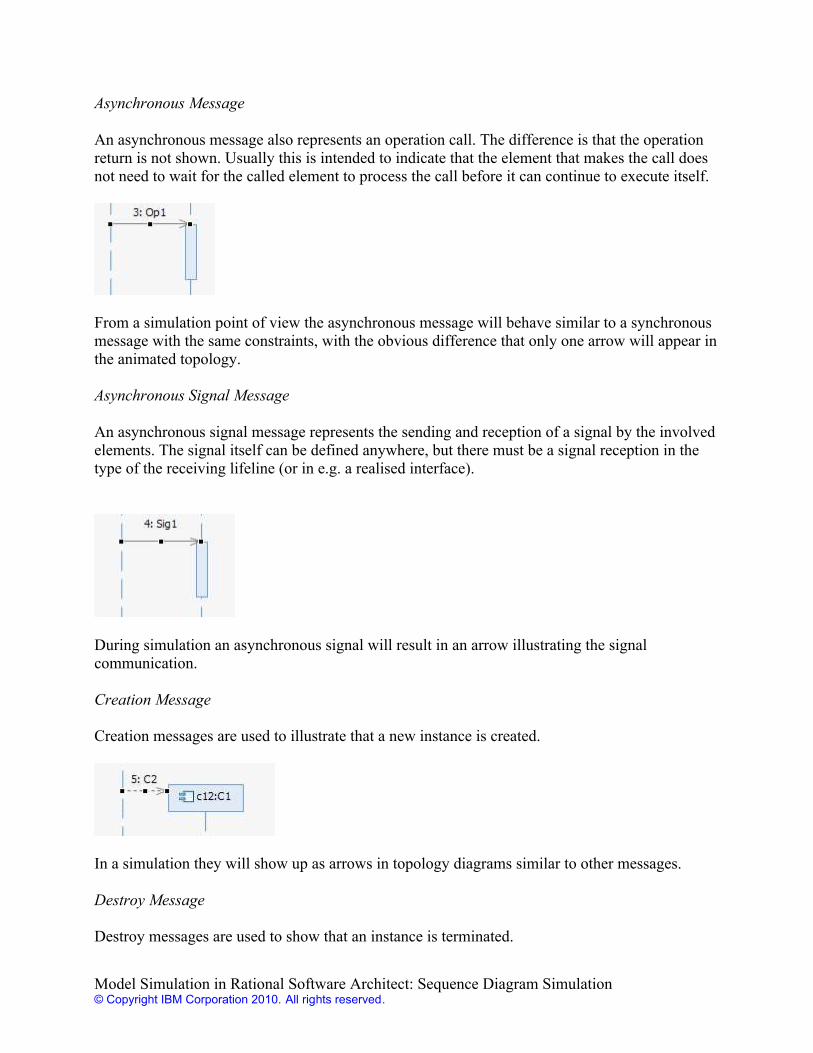
Asynchronous Message
An asynchronous message also represents an operation call. The difference is that the operationreturn is not shown. Usually this is intended to indicate that the element that makes the call doesnot need to wait for the called element to process the call before it can continue to execute itself.
From a simulation point of view the asynchronous message will behave similar to a synchronousmessage with the same constraints, with the obvious difference that only one arrow will appear inthe animated topology.
Asynchronous Signal Message
An asynchronous signal message represents the sending and reception of a signal by the involvedelements. The signal itself can be defined anywhere, but there must be a signal reception in thetype of the receiving lifeline (or in e.g. a realised interface).
During simulation an asynchronous signal will result in an arrow illustrating the signalcommunication.
Creation Message
Creation messages are used to illustrate that a new instance is created.
In a simulation they will show up as arrows in topology diagrams similar to other messages.
Destroy Message
Destroy messages are used to show that an instance is terminated.
Model Simulation in Rational Software Architect: Sequence Diagram Simulation© Copyright IBM Corporation 2010. All rights reserved.
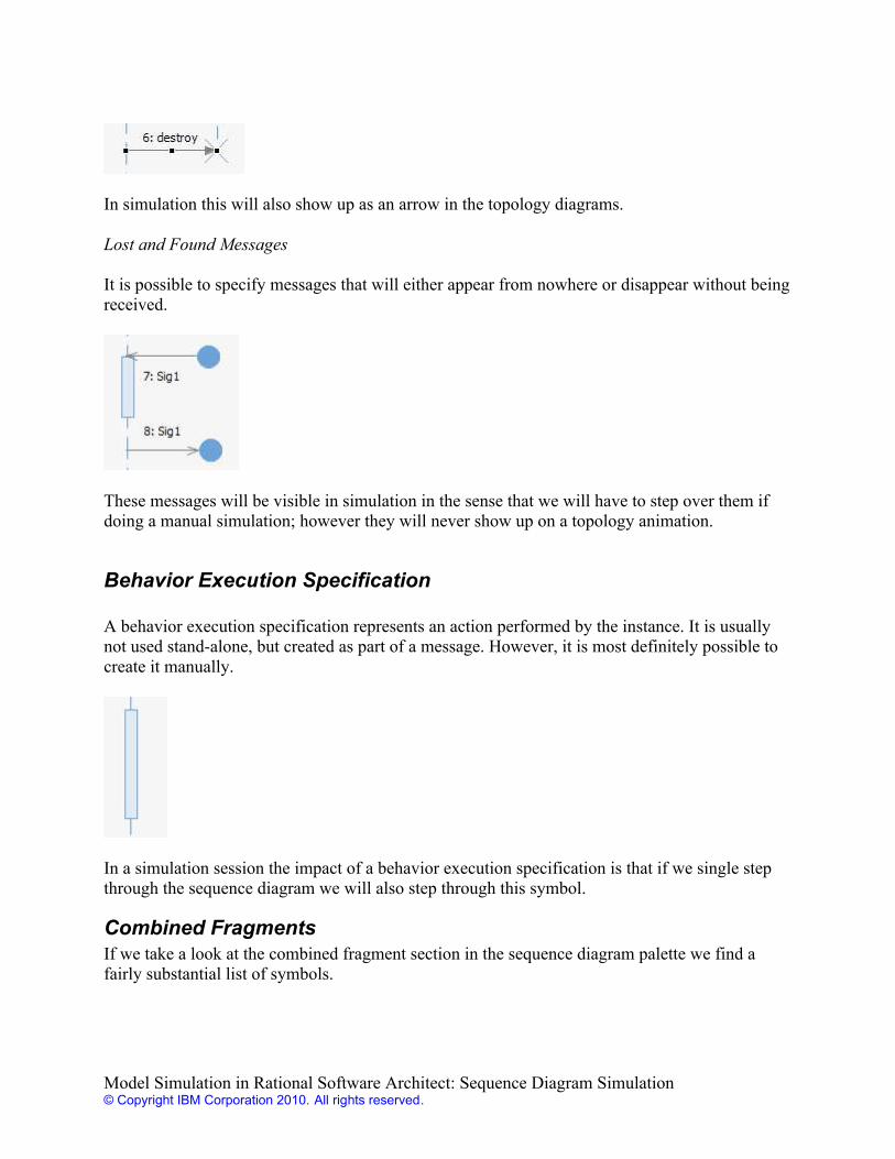
In simulation this will also show up as an arrow in the topology diagrams.
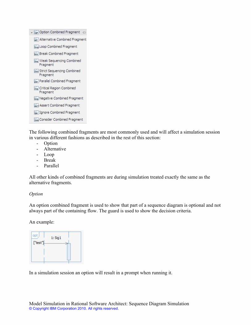
Lost and Found Messages
It is possible to specify messages that will either appear from nowhere or disappear without beingreceived.
These messages will be visible in simulation in the sense that we will have to step over them ifdoing a manual simulation; however they will never show up on a topology animation.
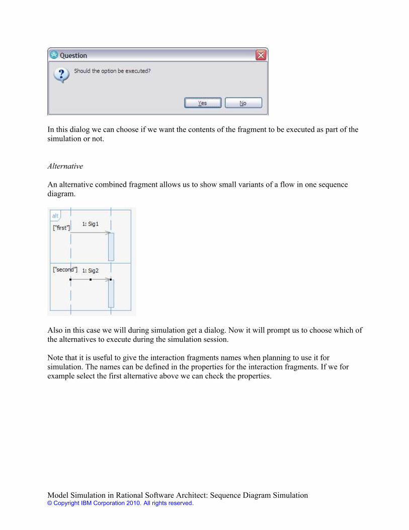
Behavior Execution Specification
A behavior execution specification represents an action performed by the instance. It is usuallynot used stand-alone, but created as part of a message. However, it is most definitely possible tocreate it manually.
In a simulation session the impact of a behavior execution specification is that if we single stepthrough the sequence diagram we will also step through this symbol.
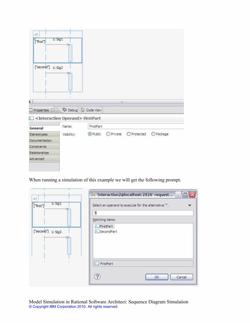
Combined FragmentsIf we take a look at the combined fragment section in the sequence diagram palette we find afairly substantial list of symbols.
Model Simulation in Rational Software Architect: Sequence Diagram Simulation© Copyright IBM Corporation 2010. All rights reserved.
The following combined fragments are most commonly used and will affect a simulation sessionin various different fashions as described in the rest of this section:
- Option- Alternative- Loop- Break- Parallel
All other kinds of combined fragments are during simulation treated exactly the same as thealternative fragments.
Option
An option combined fragment is used to show that part of a sequence diagram is optional and notalways part of the containing flow. The guard is used to show the decision criteria.
An example:
In a simulation session an option will result in a prompt when running it.
Model Simulation in Rational Software Architect: Sequence Diagram Simulation© Copyright IBM Corporation 2010. All rights reserved.
In this dialog we can choose if we want the contents of the fragment to be executed as part of thesimulation or not.
Alternative
An alternative combined fragment allows us to show small variants of a flow in one sequencediagram.
Also in this case we will during simulation get a dialog. Now it will prompt us to choose which ofthe alternatives to execute during the simulation session.
Note that it is useful to give the interaction fragments names when planning to use it forsimulation. The names can be defined in the properties for the interaction fragments. If we forexample select the first alternative above we can check the properties.
Model Simulation in Rational Software Architect: Sequence Diagram Simulation© Copyright IBM Corporation 2010. All rights reserved.
When running a simulation of this example we will get the following prompt.
Model Simulation in Rational Software Architect: Sequence Diagram Simulation© Copyright IBM Corporation 2010. All rights reserved.
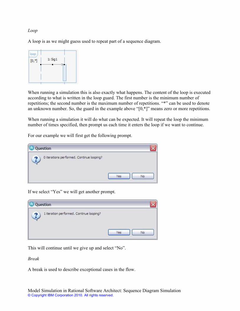
Loop
A loop is as we might guess used to repeat part of a sequence diagram.
When running a simulation this is also exactly what happens. The content of the loop is executedaccording to what is written in the loop guard. The first number is the minimum number ofrepetitions; the second number is the maximum number of repetitions. “*” can be used to denotean unknown number. So, the guard in the example above “[0,*]” means zero or more repetitions.
When running a simulation it will do what can be expected. It will repeat the loop the minimumnumber of times specified, then prompt us each time it enters the loop if we want to continue.
For our example we will first get the following prompt.
If we select “Yes” we will get another prompt.
This will continue until we give up and select “No”.
Break
A break is used to describe exceptional cases in the flow.
Model Simulation in Rational Software Architect: Sequence Diagram Simulation© Copyright IBM Corporation 2010. All rights reserved.
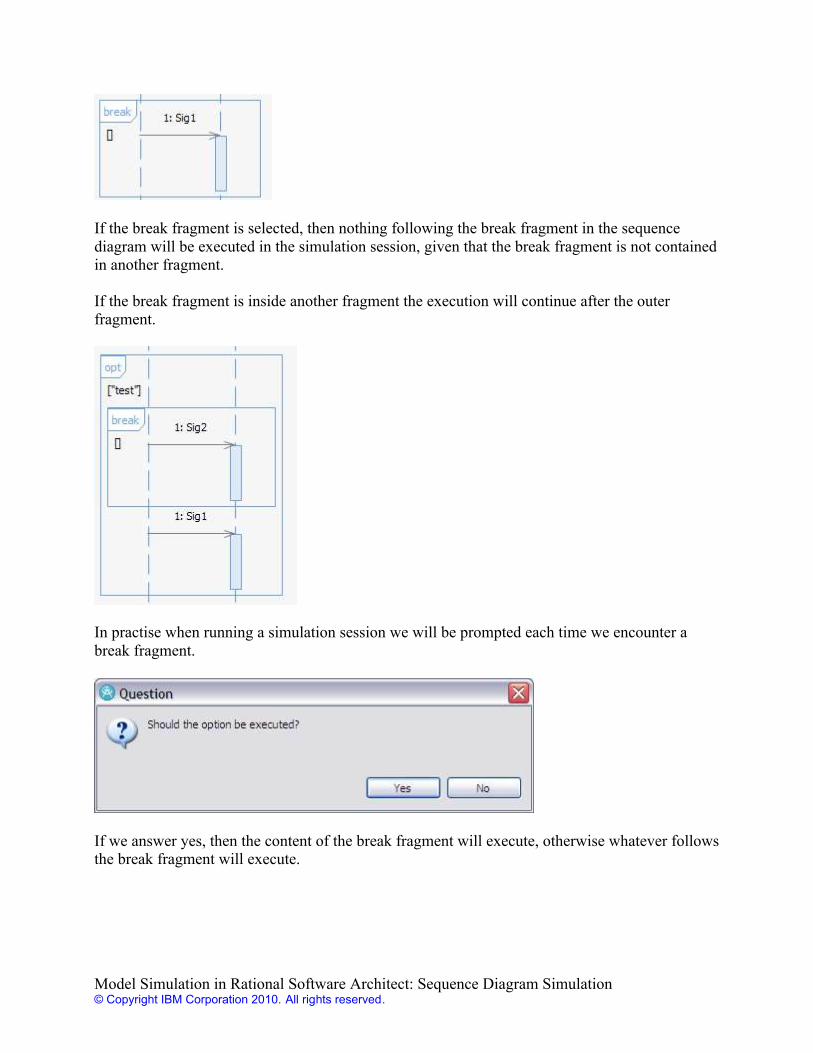
If the break fragment is selected, then nothing following the break fragment in the sequencediagram will be executed in the simulation session, given that the break fragment is not containedin another fragment.
If the break fragment is inside another fragment the execution will continue after the outerfragment.
In practise when running a simulation session we will be prompted each time we encounter abreak fragment.
If we answer yes, then the content of the break fragment will execute, otherwise whatever followsthe break fragment will execute.
Model Simulation in Rational Software Architect: Sequence Diagram Simulation© Copyright IBM Corporation 2010. All rights reserved.
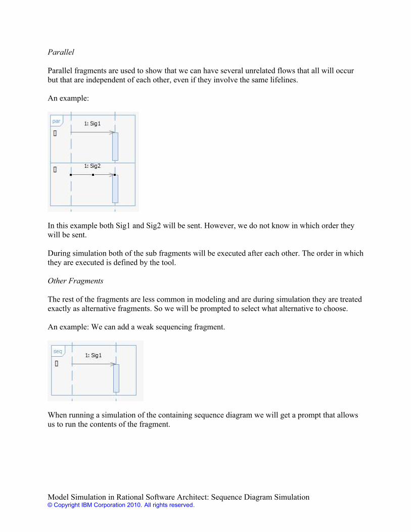
Parallel
Parallel fragments are used to show that we can have several unrelated flows that all will occurbut that are independent of each other, even if they involve the same lifelines.
An example:
In this example both Sig1 and Sig2 will be sent. However, we do not know in which order theywill be sent.
During simulation both of the sub fragments will be executed after each other. The order in whichthey are executed is defined by the tool.
Other Fragments
The rest of the fragments are less common in modeling and are during simulation they are treatedexactly as alternative fragments. So we will be prompted to select what alternative to choose.
An example: We can add a weak sequencing fragment.
When running a simulation of the containing sequence diagram we will get a prompt that allowsus to run the contents of the fragment.
Model Simulation in Rational Software Architect: Sequence Diagram Simulation© Copyright IBM Corporation 2010. All rights reserved.

Interaction Use
An interaction use gives us a possibility to invoke one sequence diagram from another sequencediagram. This is convenient to be able to reuse sequence diagrams.
Note that it is the name of the interaction that is used, not the name of the sequence diagram.
If we simulate a sequence diagram that contains an interaction use, the execution will continue inthe referenced interaction. When the referenced interaction ends, the execution will continue afterthe interaction use symbol.
Destruction event
A destruction event is used to show that an instance terminates.
Model Simulation in Rational Software Architect: Sequence Diagram Simulation© Copyright IBM Corporation 2010. All rights reserved.
From a simulation point of view we will step through this symbol if single-stepping during asimulation session.
State Invariant
Using a state invariant we can express a run-time constraint on the instance represented by thelifeline.
The actual constraint will not affect the simulation. The execution will step through the symbol ifrunning in manual mode.
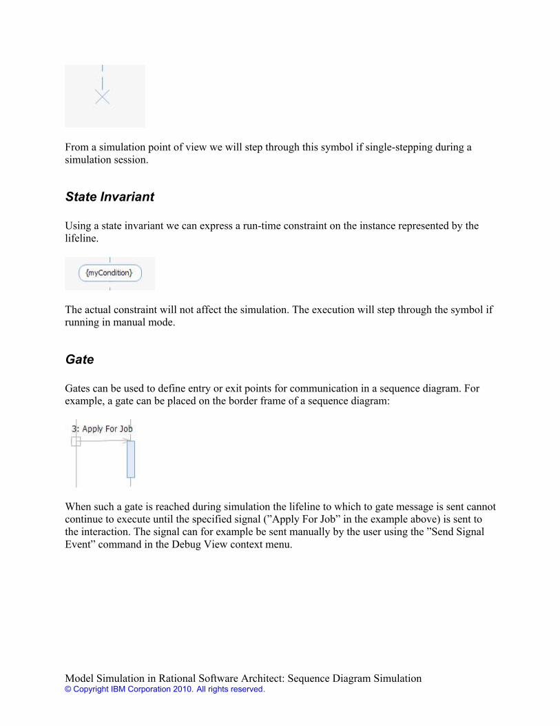
Gate
Gates can be used to define entry or exit points for communication in a sequence diagram. Forexample, a gate can be placed on the border frame of a sequence diagram:
When such a gate is reached during simulation the lifeline to which to gate message is sent cannotcontinue to execute until the specified signal (”Apply For Job” in the example above) is sent tothe interaction. The signal can for example be sent manually by the user using the ”Send SignalEvent” command in the Debug View context menu.
Model Simulation in Rational Software Architect: Sequence Diagram Simulation© Copyright IBM Corporation 2010. All rights reserved.
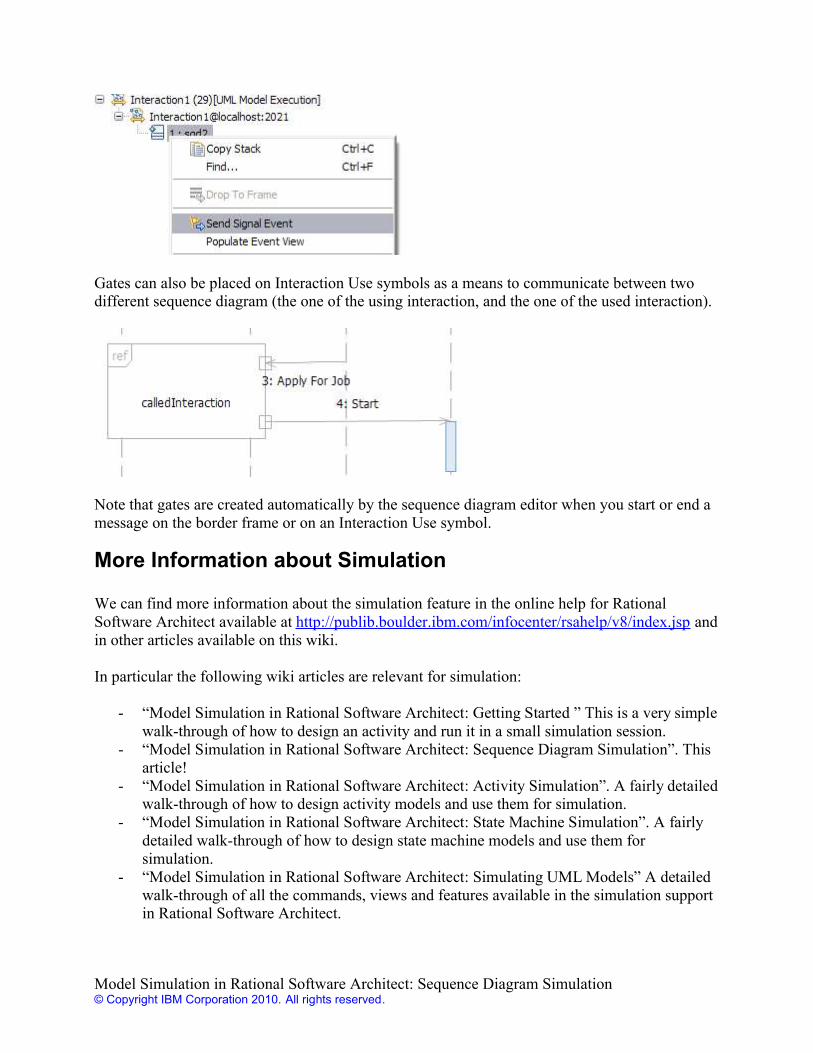
Gates can also be placed on Interaction Use symbols as a means to communicate between twodifferent sequence diagram (the one of the using interaction, and the one of the used interaction).
Note that gates are created automatically by the sequence diagram editor when you start or end amessage on the border frame or on an Interaction Use symbol.
More Information about Simulation
We can find more information about the simulation feature in the online help for RationalSoftware Architect available at http://publib.boulder.ibm.com/infocenter/rsahelp/v8/index.jsp andin other articles available on this wiki.
In particular the following wiki articles are relevant for simulation:
- “Model Simulation in Rational Software Architect: Getting Started ” This is a very simplewalk-through of how to design an activity and run it in a small simulation session.
- “Model Simulation in Rational Software Architect: Sequence Diagram Simulation”. Thisarticle!
- “Model Simulation in Rational Software Architect: Activity Simulation”. A fairly detailedwalk-through of how to design activity models and use them for simulation.
- “Model Simulation in Rational Software Architect: State Machine Simulation”. A fairlydetailed walk-through of how to design state machine models and use them forsimulation.
- “Model Simulation in Rational Software Architect: Simulating UML Models” A detailedwalk-through of all the commands, views and features available in the simulation supportin Rational Software Architect.
Model Simulation in Rational Software Architect: Sequence Diagram Simulation© Copyright IBM Corporation 2010. All rights reserved.