model sj6832 rte - rentalex
TRANSCRIPT

.
ROUGH TERRAIN SCISSORS MODEL SJ6832 RTE
167574AC December 2015
SERVICE MANUAL (ANSI/CSA)

This manual is based on Serial Number:
SJ6832RTE 37 300 001 & Above
Please refer to the website (www.skyjack.com) for older Serial Numbers.
Parts (North America)Toll Free: 1-800-965-4626Toll Free Fax: 1-888-782-4825E-mail: [email protected]
Skyjack Australia Pty Ltd.4 Coates PlaceWetherill ParkNew South Wales 2164AustraliaTel: +61 (0) 28786 3200Fax: +61(0) 28786 3222
Skyjack Brasil
Indaiatuba, SP, Brasil 13347-653Tel: +55 19 3936 0132
Alameda Júpiter, 710Loteamento American Park Empresarial
Skyjack Service Center 3451 Swenson Ave. St. Charles,
Phone: 630-262-0005Toll Free: 1-800-275-9522Fax: 630-262-0006Email: [email protected]
Illinois, 60174 USA
Parts & Service (Europe) Unit 1 Maes Y Clawdd
Oswestry, Shropshire SY10 8NN UKPhone: +44-1691-676-235Fax: +44-1691-676-238E-mail: [email protected]
Maesbury Road Industrial Estate
SKYJACK, Page 3Electric Rough Terrain SeriesModel 6832RTE167574
SERVICE AND MAINTENANCE
Table of Contents
Section 1 – Scheduled MaintenanceTable of Contents
Section 2 – Maintenance Tables Table of Contents
Section 3 – SchematicsTable of Contents
Section 4 – TroubleshootingTable of Contents
Section 5 – ProceduresTable of Contents
Electric Rough Terrain SeriesModel 6832RTE
167574
SKYJACK, Page 4
Operator’s Responsibility for MaintenanceService and Maintenance
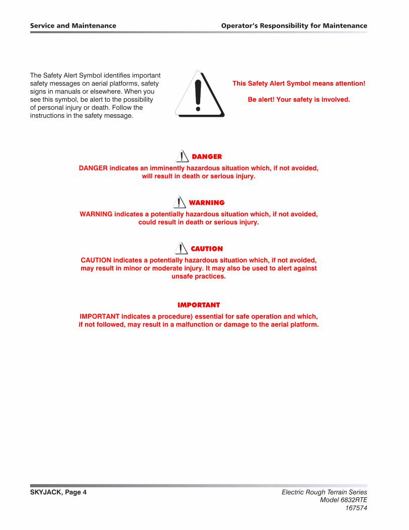
The Safety Alert Symbol identifies important safety messages on aerial platforms, safety signs in manuals or elsewhere. When you see this symbol, be alert to the possibility of personal injury or death. Follow the instructions in the safety message.
This Safety Alert Symbol means attention!
Be alert! Your safety is involved.
DANGER
DANGER indicates an imminently hazardous situation which, if not avoided, will result in death or serious injury.
WARNING
WARNING indicates a potentially hazardous situation which, if not avoided, could result in death or serious injury.
CAUTION
CAUTION indicates a potentially hazardous situation which, if not avoided, may result in minor or moderate injury. It may also be used to alert against
unsafe practices.
IMPORTANT
IMPORTANT indicates a procedure) essential for safe operation and which, if not followed, may result in a malfunction or damage to the aerial platform.

SKYJACK, Page 5Electric Rough Terrain SeriesModel 6832RTE167574
1 Section 1SCHEDULED MAINTENANCE
Table of Contents
Operator’s Responsibility for MaintenanceAerial Platform Definition ..............................................................................................................................................6Purpose of Equipment .................................................................................................................................................6Use of Equipment ........................................................................................................................................................6Product Manuals .........................................................................................................................................................6Service Policy and Warranty ........................................................................................................................................6Operator Safety Reminders, Warnings, and Precautions ...........................................................................................6Maintenance and Inspection Schedule .......................................................................................................................6Owner’s Annual Inspection Record .............................................................................................................................6Replacement Parts .......................................................................................................................................................6Maintenance and Service Safety Tips .........................................................................................................................7Hydraulic System & Component Maintenance and Repair ........................................................................................7Maintenance Hints .......................................................................................................................................................8
Service and MaintenanceAbout this Section ........................................................................................................................................................9Service Bulletins ...........................................................................................................................................................9Maintenance and Inspection .......................................................................................................................................9Maintenance and Inspection .......................................................................................................................................9
TablesTable 1.1 Owner’s Annual Inspection Record ...........................................................................................................10Table 1.2 Pre-Delivery/Maintenance Inspection Checklist ........................................................................................11
Service and Maintenance Inspections1.1 Scheduled Maintenance Inspections ...........................................................................................................121.2 Function Tests ...............................................................................................................................................22
Electric Rough Terrain SeriesModel 6832RTE
167574
SKYJACK, Page 6
Operator’s Responsibility for MaintenanceService and Maintenance
Operator’s Responsibility for MaintenanceSKYJACK is continuously improving and expanding product features on its equipment; therefore, specifications and dimensions are subject to change without notice.
Aerial Platform DefinitionA mobile device that has an adjustable position platform supported from ground level by a structure.
Purpose of EquipmentThe SKYJACK Rough Terrain Compact Electric Series Aerial platform are designed to transport and raise personnel, tools and materials to overhead work areas.
Use of EquipmentThe Aerial platform is a highly maneuverable, mobile work station. Work platform elevation and elevated driving must only be done on a firm, level surface. It can be driven over uneven terrain only when the platform is fully lowered.
Product Manuals The Operating Manual is considered a fundamental part of the Aerial platform. It is a very important way to communicate necessary safety information to users and operators. A complete and legible copy of this manual must be kept in the provided weather-resistant storage compartment on the Aerial platform at all times.
The Service Manual provides the customer with the servicing and maintenance procedures essential for the promotion of proper machine operation for its intended purpose.
All information in this manual should be read and understood before any attempt is made to service the machine. This manual may be revised after printing, so for the very latest issue go to the company’s website at: www.skyjack.com.
Service Policy and WarrantySKYJACK warrants each new SJRT Compact Series work platform to be free of defective parts and workmanship for the first 24 months. Any defective part will be replaced or repaired by your local SKYJACK dealer at no charge for parts or labor. Contact the SKYJACK Service Department for warranty statement extensions or exclusions
Operator Safety Reminders, Warnings, and PrecautionsOperator safety is SKYJACK’s priority. The operator should comply with all applicable safety-related reminders, warnings and precautions found in the Operating Manual. It should be read and understood completely before operating the Aerial platform.
Maintenance and Inspection ScheduleThe actual operating environment of the work platform governs the use of the maintenance schedule. The inspection points covered in Table 1.2 Maintenance and lnspection Checklist, indicates the areas of the Aerial platform to be maintained or inspected and at what intervals the maintenance and inspections are to be performed.
Owner’s Annual Inspection RecordIt is the responsibility of the owner to arrange quarterly and annual inspections of the Aerial platform. Table 1.1 Owner’s Annual lnspection Record is to be used for recording the date of the inspection, owner’s name, and the person responsible for the inspection of the work platform.
Replacement PartsUse only original replacement parts. Parts such as batteries, wheels, railings, etc. with weight and dimensions different from original parts will affect stability of the work platform and must not be used without manufacturer’s consent.
Use only original filled tires for models which must be so equipped. Consult factory.
All replacement tires must be of the same size and load rating as original equipment to maintain safety and stability of the work platform. Consult factory.
WARNING
Any unit that is damaged or not operating properly must be immediately tagged and removed from service until proper repairs are completed.

SKYJACK, Page 7Electric Rough Terrain SeriesModel 6832RTE167574
Operator’s Responsibility for Maintenance Service and Maintenance
Maintenance and Service Safety Tips• Maintenance and repairs should only be
performed by personnel who are trained and qualified to service this aerial platform.
• All maintenance and service procedures should be performed in a well lighted and well ventilated area.
• Anyone operating or servicing this aerial platform must read and completely understand all operating instructions and safety hazards in this manual and the operator's manual.
• All tools, supports and lifting equipment to be used must be of proper rated load and in good working order before any service work begins. Work area should be kept clean and free of debris to avoid contaminating components while servicing.
• All service personnel must be familiar with employer and governmental regulations that apply to servicing this type of equipment.
• Keep sparks and flames away from all flammable or combustible materials.
• Properly dispose of all waste material such as lubricants, rags, and old parts according to the local law provisions in the country of operation.
• Before attempting any repair work, turn Battery Disconnect Switch to the OFF position.
Preventive maintenance is the easiest and least expensive type of maintenance.
Hydraulic System & Component Maintenance and RepairThe following points should be kept in mind when working on the hydraulic system or any component:
WARNING
Escaping fluid from a hydraulic pressure leak can damage your eyes, penetrate the skin and cause serious injury. Use proper personal protection at all times.
1. Any structure has limits of strength and durability. To prevent failure of structural parts of hydraulic components, relief valves which limit pressure to safe operating values are included in the hydraulic circuits.
2. Tolerance of working parts in the hydraulic system is very close. Even small amounts of dirt or foreign materials in the system can cause wear or damage to components, as well as general faulty operation of the hydraulic system. Every precaution must be taken to assure absolute cleanliness of the hydraulic oil.
3. Whenever there is a hydraulic system failure which gives reason to believe that there are metal particles or foreign materials in the system, drain and flush the entire system and replace the filter cartridges. A complete change of oil must be made under these circumstances.
4. Whenever the hydraulic system is drained, check the magnets in the hydraulic reservoir for metal particles. If metal particles are present, flush the entire system and add a new change of oil. The presence of metal particles also may indicate the possibility of imminent component failure. A very small amount of fine particles is normal.
5. All containers and funnels used in handling hydraulic oil must be absolutely clean. Use a funnel when necessary for filling the hydraulic oil reservoir, and fill the reservoir only through the filter opening. The use of cloth to strain the oil should be avoided to prevent lint from getting into the system.
6. When removing any hydraulic component, be sure to cap and tag all hydraulic lines involved. Also, plug the ports of the removed components.
Electric Rough Terrain SeriesModel 6832RTE
167574
SKYJACK, Page 8
Operator’s Responsibility for MaintenanceService and Maintenance
NOTE: Samples of hydraulic oil should be drawn from the reservoir and tested annually. These samples should be taken when the oil is warmed through normal operation of the system. The sample should be analyzed by a qualified lubrication specialist to determine if it is suitable for continued use. Oil change intervals will depend on the care used in keeping the oil clean, and the operating conditions. Dirt and/or moisture contamination will dictate that the oil should be changed more often. Under normal use and operating conditions, the hydraulic oil should be changed every two years. Refer to Table 1.2 of this manual.
7. All hydraulic components must be disassembled in spotlessly clean surroundings. During disassembly, pay particular attention to the identification of parts to assure proper reassembly. Clean all metal parts in a clean mineral oil solvent. Be sure to thoroughly clean all internal passages. After the parts have been dried thoroughly, lay them on a clean, lint-free surface for inspection.
8. Replace all O-rings and seals when overhauling any component. Lubricate all parts with clean hydraulic oil before reassembly. Use small amounts of petroleum jelly to hold O-rings in place during assembly.
9. Be sure to replace any lost hydraulic oil when completing the installation of the repaired component, and bleed any air from the system when required.
10. All hydraulic connections must be kept tight. A loose connection in a pressure line will permit the oil to leak out or air to be drawn into the system. Air in the system can cause damage to the components and noisy or erratic system operation.
Maintenance HintsThree simple maintenance procedures have the greatest effect on the hydraulic system performance, efficiency, and life:
1. Change filters annually. The filters will need to be changed more often depending on the operating conditions. Dirty, dusty, high moisture environments may cause the hydraulic system to be contaminated more quickly.
2. Maintain a sufficient quantity of clean hydraulic oil of the proper type and viscosity in the hydraulic reservoir.
3. Keep all connections tight.
SKYJACK, Page 9Electric Rough Terrain SeriesModel 6832RTE167574
Scheduled Maintenance Service and Maintenance Inspections
Service and Maintenance
About this SectionThis section contains the maintenance and inspection schedule that is to be performed. Instructions for specific procedures are found in Section 5.
Service BulletinsBefore performing any scheduled maintenance inspection procedure, check for any service bulletins related to service and maintenance of this aerial platform at: www.skyjack.com.
Maintenance and InspectionDeath or injury can result if the aerial platform is not kept in good working order. Inspection and maintenance should be performed by competent personnel who are trained and qualified on maintenance of this aerial platform.
WARNING
Risk of death, serious injury or substantial machine damage. Always perform each pro-cedure as described at the scheduled interval.
NOTE: Preventive maintenance is the easiest and least expensive type of maintenance.
Unless otherwise specified, perform each maintenance procedure with the aerial platform in the following configuration:
• Parked on a flat and level surface.
• Battery disconnected by turning the main power disconnect switch to the OFF position.
Repair any damaged or malfunction components before operating aerial platform.
Keep records on all inspections.
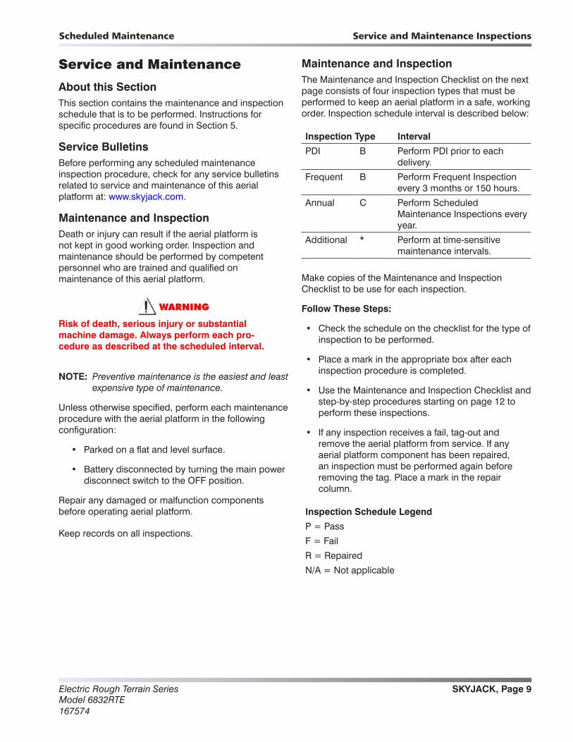
Maintenance and InspectionThe Maintenance and Inspection Checklist on the next page consists of four inspection types that must be performed to keep an aerial platform in a safe, working order. Inspection schedule interval is described below:
Inspection Type Interval
PDI B Perform PDI prior to each delivery.
Frequent B Perform Frequent Inspection every 3 months or 150 hours.
Annual C Perform Scheduled Maintenance Inspections every year.
Additional * Perform at time-sensitive maintenance intervals.
Make copies of the Maintenance and Inspection Checklist to be use for each inspection.
Follow These Steps:
• Check the schedule on the checklist for the type of inspection to be performed.
• Place a mark in the appropriate box after each inspection procedure is completed.
• Use the Maintenance and Inspection Checklist and step-by-step procedures starting on page 12 to perform these inspections.
• If any inspection receives a fail, tag-out and remove the aerial platform from service. If any aerial platform component has been repaired, an inspection must be performed again before removing the tag. Place a mark in the repair column.
Inspection Schedule Legend
P = Pass
F = Fail
R = Repaired
N/A = Not applicable
Electric Rough Terrain SeriesModel 6832RTE
167574
SKYJACK, Page 10
Scheduled MaintenanceService and Maintenance Inspections
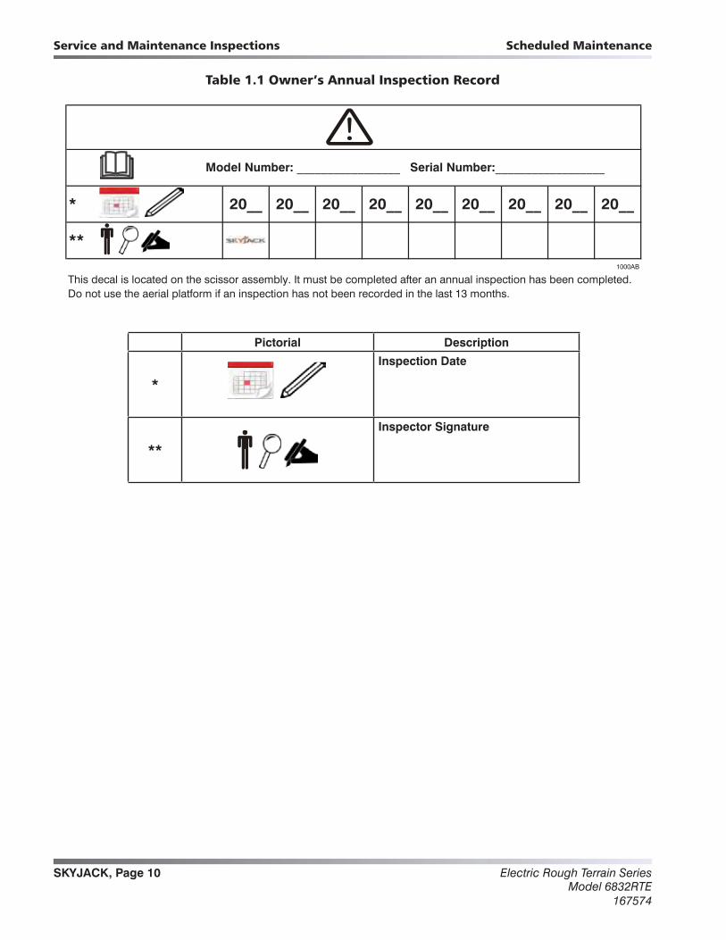
Table 1.1 Owner’s Annual Inspection Record
1000AB
This decal is located on the scissor assembly. It must be completed after an annual inspection has been completed. Do not use the aerial platform if an inspection has not been recorded in the last 13 months.
20__ 20__ 20__
**
Model Number: _________________ Serial Number:__________________
* 20__ 20__ 20__ 20__ 20__ 20__
Pictorial Description
*
Inspection Date
**
Inspector Signature
Tables
SKYJACK, Page 11Electric Rough Terrain SeriesModel 6832RTE167574
Scheduled Maintenance Service and Maintenance Inspections
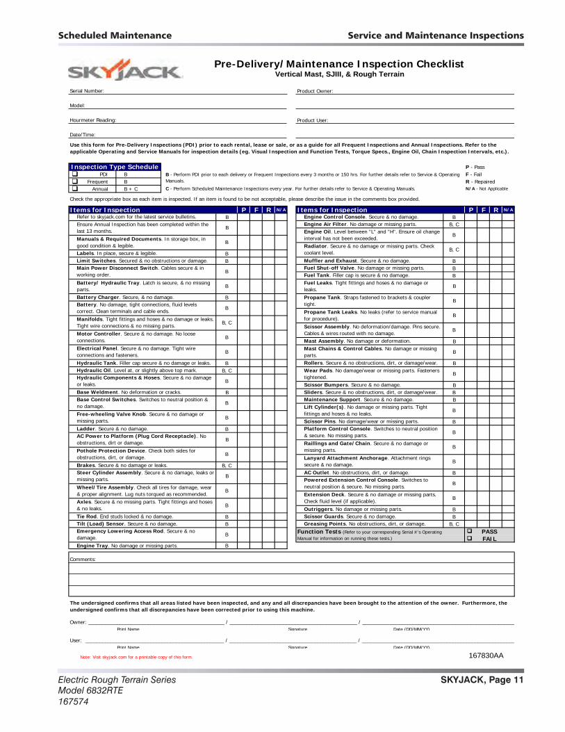
Table 1.2 Pre-Delivery/Maintenance Inspection Checklist
Note: Visit skyjack.com for a printable copy of this form. 167830AA
Serial Number: Product Owner:
Model:
Hourmeter Reading: Product User:
Date/Time:
P - Pass PDI B F - Fail Frequent B R - Repaired Annual B + C
Items for Inspection P F R N/A Items for Inspection P F R N/A
B BB, C
BB B
BB
B
B
B BB, C
BB B
B
BB
B, CB
BB BB B, C
B
Owner: ________________________________________________ / _____________________________________________ / ______________________________________________________Print Name Signature Date (DD/MM/YY)
User: _________________________________________________ / _____________________________________________ / ______________________________________________________Print Name Signature Date (DD/MM/YY)
Comments:
Motor Controller. Secure & no damage. No loose connections.
B
Steer Cylinder Assembly. Secure & no damage, leaks or missing parts.
B
Ladder. Secure & no damage.
Brakes. Secure & no damage or leaks.
AC Power to Platform (Plug Cord Receptacle). No obstructions, dirt or damage.
B
Emergency Lowering Access Rod. Secure & no damage.
B
Base Control Switches. Switches to neutral position & no damage.
B
Axles. Secure & no missing parts. Tight fittings and hoses & no leaks.
Pothole Protection Device. Check both sides for obstructions, dirt, or damage.
PASSFAIL
Platform Control Console. Switches to neutral position & secure. No missing parts.Raillings and Gate/Chain. Secure & no damage or missing parts.Lanyard Attachment Anchorage. Attachment rings secure & no damage.
Scissor Guards. Secure & no damage.Greasing Points. No obstructions, dirt, or damage.
Function Tests (Refer to your corresponding Serial #'s Operating Manual for information on running these tests.)
Engine Tray. No damage or missing parts.
Engine Control Console. Secure & no damage.Engine Air Filter. No damage or missing parts.
Electrical Panel. Secure & no damage. Tight wire connections and fasteners.
Engine Oil. Level between "L" and "H". Ensure oil change interval has not been exceeded.
B
Refer to skyjack.com for the latest service bulletins.
Radiator. Secure & no damage or missing parts. Check coolant level.
Main Power Disconnect Switch. Cables secure & in working order.
B
AC Outlet. No obstructions, dirt, or damage.
Outriggers. No damage or missing parts.
Tilt (Load) Sensor. Secure & no damage.
B
B
Ensure Annual Inspection has been completed within the last 13 months.
Wheel/Tire Assembly. Check all tires for damage, wear & proper alignment. Lug nuts torqued as recommended.
B
Propane Tank. Straps fastened to brackets & coupler tight.
B
Tie Rod. End studs locked & no damage.
Battery Charger. Secure, & no damage.
Hydraulic Tank. Filler cap secure & no damage or leaks.
Use this form for Pre-Delivery Inspections (PDI) prior to each rental, lease or sale, or as a guide for all Frequent Inspections and Annual Inspections. Refer to the applicable Operating and Service Manuals for inspection details (eg. Visual Inspection and Function Tests, Torque Specs., Engine Oil, Chain Inspection Intervals, etc.).
Pre-Delivery/Maintenance Inspection Checklist
Mast Assembly. No damage or deformation.
Rollers. Secure & no obstructions, dirt, or damage/wear.
Sliders. Secure & no obstructions, dirt, or damage/wear.Maintenance Support. Secure & no damage.Lift Cylinder(s). No damage or missing parts. Tight fittings and hoses & no leaks.
Fuel Tank. Filler cap is secure & no damage.
B - Perform PDI prior to each delivery or Frequent Inspections every 3 months or 150 hrs. For further details refer to Service & Operating Manuals.
Mast Chains & Control Cables. No damage or missing parts.
B
Free-wheeling Valve Knob. Secure & no damage or missing parts.
Base Weldment. No deformation or cracks.
Manifolds. Tight fittings and hoses & no damage or leaks. Tight wire connections & no missing parts.
Manuals & Required Documents. In storage box, in good condition & legible.
B
Vertical Mast, SJIII, & Rough Terrain
C - Perform Scheduled Maintenance Inspections every year. For further details refer to Service & Operating Manuals.
B
Battery. No damage, tight connections, fluid levels correct. Clean terminals and cable ends.
Muffler and Exhaust. Secure & no damage.Fuel Shut-off Valve. No damage or missing parts.
Scissor Assembly. No deformation/damage. Pins secure. Cables & wires routed with no damage.
Battery/ Hydraulic Tray. Latch is secure, & no missing parts.
B
BB
Check the appropriate box as each item is inspected. If an item is found to be not acceptable, please describe the issue in the comments box provided.
Labels. In place, secure & legible.
Inspection Type Schedule
B
B
B
B, C
Scissor Bumpers. Secure & no damage.
Limit Switches. Secured & no obstructions or damage.
Hydraulic Components & Hoses. Secure & no damage or leaks.
Hydraulic Oil. Level at, or slightly above top mark.
B
N/A - Not Applicable
B
Powered Extension Control Console. Switches to neutral position & secure. No missing parts.
B
B
B
B, C
Fuel Leaks. Tight fittings and hoses & no damage or leaks.
B
The undersigned confirms that all areas listed have been inspected, and any and all discrepancies have been brought to the attention of the owner. Furthermore, the undersigned confirms that all discrepancies have been corrected prior to using this machine.
Propane Tank Leaks. No leaks (refer to service manual for procedure).
B
Scissor Pins. No damage/wear or missing parts.
Wear Pads. No damage/wear or missing parts. Fasteners tightened.
B
B
Extension Deck. Secure & no damage or missing parts. Check fluid level (if applicable).
Electric Rough Terrain SeriesModel 6832RTE
167574
SKYJACK, Page 12
Scheduled MaintenanceService and Maintenance Inspections
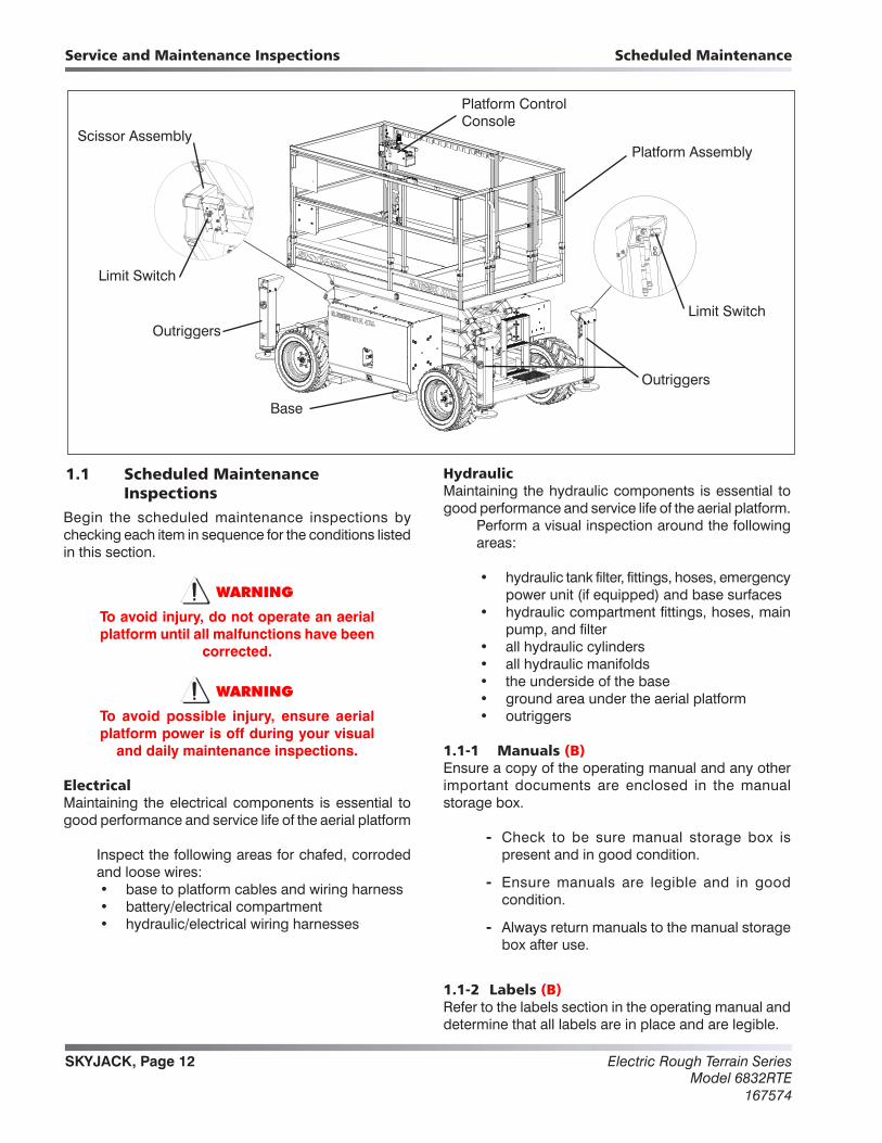
1.1 Scheduled Maintenance Inspections
Begin the scheduled maintenance inspections by checking each item in sequence for the conditions listed in this section.
WARNING
To avoid injury, do not operate an aerial platform until all malfunctions have been
corrected.
WARNING
To avoid possible injury, ensure aerial platform power is off during your visual
and daily maintenance inspections.
ElectricalMaintaining the electrical components is essential to good performance and service life of the aerial platform
Inspect the following areas for chafed, corroded and loose wires:• base to platform cables and wiring harness• battery/electrical compartment• hydraulic/electrical wiring harnesses
HydraulicMaintaining the hydraulic components is essential to good performance and service life of the aerial platform.
Perform a visual inspection around the following areas:
• hydraulic tank filter, fittings, hoses, emergency power unit (if equipped) and base surfaces
• hydraulic compartment fittings, hoses, main pump, and filter
• all hydraulic cylinders• all hydraulic manifolds• the underside of the base• ground area under the aerial platform• outriggers
1.1-1 Manuals (B)Ensure a copy of the operating manual and any other important documents are enclosed in the manual storage box.
- Check to be sure manual storage box is present and in good condition.
- Ensure manuals are legible and in good condition.
- Always return manuals to the manual storage box after use.
1.1-2 Labels (B)Refer to the labels section in the operating manual and determine that all labels are in place and are legible.
Base
Outriggers
Platform AssemblyScissor Assembly
Limit Switch
Platform Control Console
Outriggers
Limit Switch
Service and Maintenance Inspections
SKYJACK, Page 13Electric Rough Terrain SeriesModel 6832RTE167574
Scheduled Maintenance Service and Maintenance Inspections
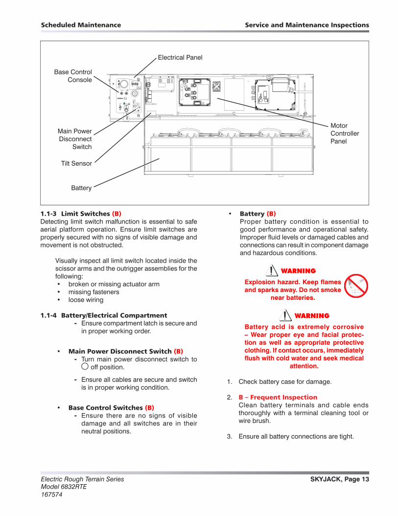
1.1-3 Limit Switches (B)Detecting limit switch malfunction is essential to safe aerial platform operation. Ensure limit switches are properly secured with no signs of visible damage and movement is not obstructed.
Visually inspect all limit switch located inside the scissor arms and the outrigger assemblies for the following:• broken or missing actuator arm• missing fasteners• loose wiring
1.1-4 Battery/Electrical Compartment - Ensure compartment latch is secure and
in proper working order.
• Main Power Disconnect Switch (B) - Turn main power disconnect switch to
off position.
- Ensure all cables are secure and switch is in proper working condition.
• Base Control Switches (B) - Ensure there are no signs of visible
damage and all switches are in their neutral positions.
• Battery (B) Proper battery condition is essential to
good performance and operational safety. Improper fluid levels or damaged cables and connections can result in component damage and hazardous conditions.
WARNING
Explosion hazard. Keep flames and sparks away. Do not smoke
near batteries.
WARNING
Battery acid is extremely corrosive – Wear proper eye and facial protec-tion as well as appropriate protective clothing. If contact occurs, immediately flush with cold water and seek medical
attention.
1. Check battery case for damage.
2. B – Frequent Inspection Clean battery terminals and cable ends
thoroughly with a terminal cleaning tool or wire brush.
3. Ensure all battery connections are tight.
Main Power Disconnect
Switch
Battery
Base Control Console
Tilt Sensor
Motor ControllerPanel
Electrical Panel

Electric Rough Terrain SeriesModel 6832RTE
167574
SKYJACK, Page 14
Scheduled MaintenanceService and Maintenance Inspections
4. If applicable, check battery fluid level.
B – Frequent Inspection If plates are not covered by at least 1/2
in. (13 mm) of solution, add distilled or demineralized water.
5. B – Frequent Inspection Replace battery if damaged or incapable of
holding a lasting charge.
WARNING
Use original or manufacturer-approved parts and components for the aerial
platform.
• Tilt Sensor (B) - Ensure tilt sensor is properly secured and
there is no visible damage.
• Motor Controller Panel (B) - Ensure motor controller panel is properly
secured and there is no visible damage.
- Ensure there are no loose wire connections or missing fasteners.
• Electrical Panel (B) - Ensure panel is properly secured and
there is no visible damage.
- Ensure there are no loose wire connections or missing fasteners.
Main Power Disconnect
Switch
Battery
Base Control Console
Tilt Sensor
Motor ControllerPanel
Electrical Panel

SKYJACK, Page 15Electric Rough Terrain SeriesModel 6832RTE167574
Scheduled Maintenance Service and Maintenance Inspections
1.1-5 Motor/Hydraulic Compartment - Ensure compartment latch is secure and
in proper working order.
• Hydraulic Tank (B) - Ensure hydraulic filler cap is secure.
- Ensure tank shows no visible damage and no evidence of hydraulic leakage.
• Hydraulic Oil (B,C) - Ensure platform is fully lowered, and
outriggers retracted, and then visually inspect the sight gauge located on the side of the hydraulic oil tank. Check oil level against label that indicates minimum and maximum oil levels.
C – Annual Inspection - Refer to Section 1 - Hydraulic System
& Component Maintenance and Repair.
• Hydraulic Return Filter (B) - Ensure filter element is secure.
- Ensure there are no signs of leakage or visible damage.
• Hydraulic Pump & Motor (B) - Ensure there are no loose or missing
parts and there is no visible damage.
- Ensure all bolts are properly tightened.
- Ensure all fittings and hoses are properly tightened and there is no evidence of hydraulic leakage.
• Main Manifold (B,C) - Ensure all fittings and hoses are properly
tightened and there is no evidence of hydraulic leakage.
- Ensure there are no loose wire connections or missing fasteners.
• Gear Type Flow Divider (B) - Ensure there are no loose or missing
parts and there is no visible damage.
Hydraulic Tank
Hydraulic Oil Filter
Gear Type Flow Divider
Main Manifold
Oil Level Gauge
Hydraulic Pump and Motor

Electric Rough Terrain SeriesModel 6832RTE
167574
SKYJACK, Page 16
Scheduled MaintenanceService and Maintenance Inspections
1.1-6 Platform Assembly
WARNING
Ensure that you maintain three points of contact to mount/dismount platform.
1. Use the ladder of aerial platform to access platform.
2. Close the gate.
- Ensure there are no loose or missing parts and there is no visible damage.
- Ensure all fasteners are securely in place.
- Ensure all railings are properly positioned and secured.
- Ensure gate is in good working order.
• Fall Protection Anchorage (B) - Ensure attachment rings are secure and
have no visible damage.
• AC Outlet on Platform (B) - Ensure outlet has no visible damage and
free from dirt or obstructions.
• Platform Control Console (B) - Ensure all switches and controller are
returned to neutral and are properly secured.
- Ensure there are no loose or missing parts and there is no visible damage.
WARNING
Ensure that you maintain three points of contact to mount/dismount platform.
3. Use the ladder to dismount from platform.
• Extension Deck (If Equipped) (B) - Ensure assembly is securely attached to
the bottom of the platform.
- Ensure there are no loose or missing parts and there is no visible damage or leaks.
Platform Assembly
Platform Control Console
Platform Railing
Manuals
Extension DeckAC Outlet
Fall Protection Anchorage
AC
SKYJACK, Page 17Electric Rough Terrain SeriesModel 6832RTE167574
Scheduled Maintenance Service and Maintenance Inspections
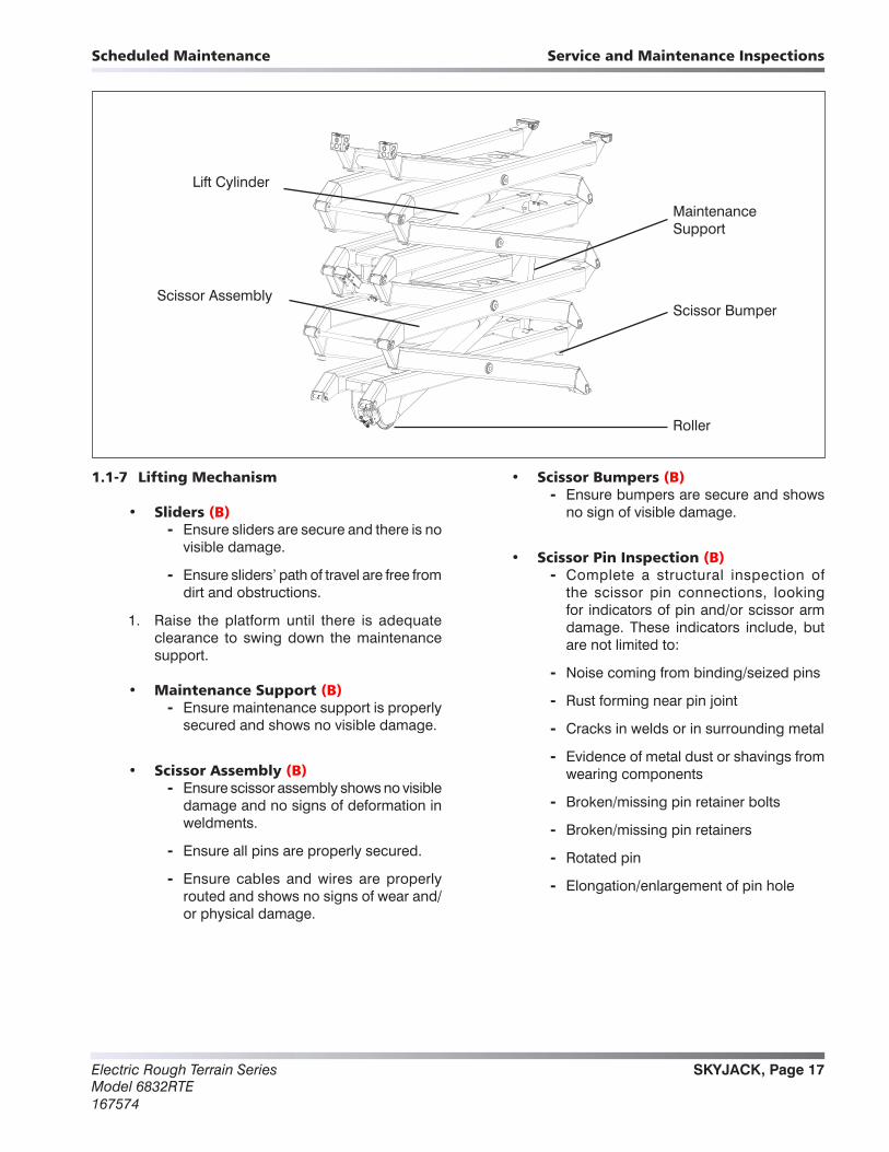
1.1-7 Lifting Mechanism
• Sliders (B) - Ensure sliders are secure and there is no
visible damage.
- Ensure sliders’ path of travel are free from dirt and obstructions.
1. Raise the platform until there is adequate clearance to swing down the maintenance support.
• Maintenance Support (B) - Ensure maintenance support is properly
secured and shows no visible damage.
• Scissor Assembly (B) - Ensure scissor assembly shows no visible
damage and no signs of deformation in weldments.
- Ensure all pins are properly secured.
- Ensure cables and wires are properly routed and shows no signs of wear and/or physical damage.
• Scissor Bumpers (B) - Ensure bumpers are secure and shows
no sign of visible damage.
• Scissor Pin Inspection (B) - Complete a structural inspection of
the scissor pin connections, looking for indicators of pin and/or scissor arm damage. These indicators include, but are not limited to:
- Noise coming from binding/seized pins
- Rust forming near pin joint
- Cracks in welds or in surrounding metal
- Evidence of metal dust or shavings from wearing components
- Broken/missing pin retainer bolts
- Broken/missing pin retainers
- Rotated pin
- Elongation/enlargement of pin hole
Scissor Assembly
Maintenance Support
Lift Cylinder
Scissor Bumper
Roller
Electric Rough Terrain SeriesModel 6832RTE
167574
SKYJACK, Page 18
Scheduled MaintenanceService and Maintenance Inspections
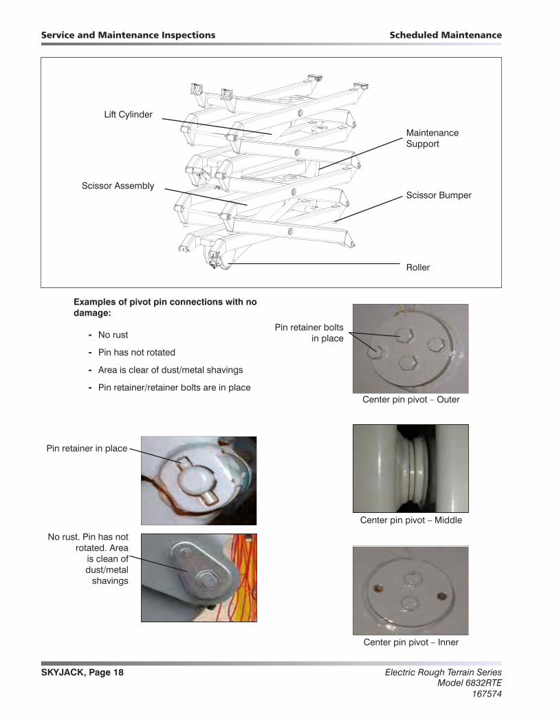
Scissor Assembly
Maintenance Support
Lift Cylinder
Scissor Bumper
Roller
Examples of pivot pin connections with no damage:
- No rust
- Pin has not rotated
- Area is clear of dust/metal shavings
- Pin retainer/retainer bolts are in place
Pin retainer in place
No rust. Pin has not rotated. Area
is clean of dust/metal
shavings
Center pin pivot – Inner
Center pin pivot – Middle
Center pin pivot – Outer
Pin retainer boltsin place
SKYJACK, Page 19Electric Rough Terrain SeriesModel 6832RTE167574
Scheduled Maintenance Service and Maintenance Inspections
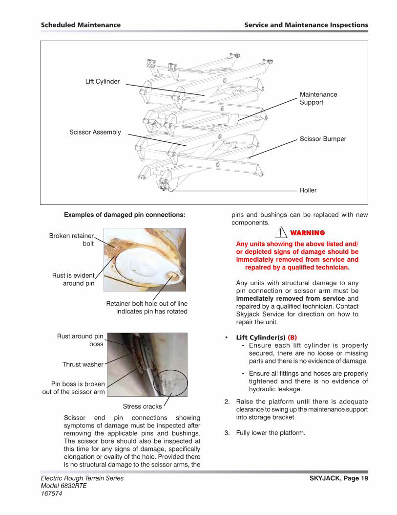
Scissor Assembly
Maintenance Support
Lift Cylinder
Scissor Bumper
Roller
Examples of damaged pin connections:
Scissor end pin connections showing symptoms of damage must be inspected after removing the applicable pins and bushings. The scissor bore should also be inspected at this time for any signs of damage, specifically elongation or ovality of the hole. Provided there is no structural damage to the scissor arms, the
pins and bushings can be replaced with new components.
WARNING
Any units showing the above listed and/or depicted signs of damage should be immediately removed from service and
repaired by a qualified technician.
Any units with structural damage to any pin connection or scissor arm must be immediately removed from service and repaired by a qualified technician. Contact Skyjack Service for direction on how to repair the unit.
• Lift Cylinder(s) (B) - Ensure each lift cylinder is properly
secured, there are no loose or missing parts and there is no evidence of damage.
- Ensure all fittings and hoses are properly tightened and there is no evidence of hydraulic leakage.
2. Raise the platform until there is adequate clearance to swing up the maintenance support into storage bracket.
3. Fully lower the platform.
Broken retainer bolt
Rust is evident around pin
Retainer bolt hole out of line indicates pin has rotated
Rust around pinboss
Pin boss is brokenout of the scissor arm
Thrust washer
Stress cracks
Electric Rough Terrain SeriesModel 6832RTE
167574
SKYJACK, Page 20
Scheduled MaintenanceService and Maintenance Inspections
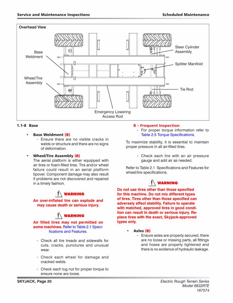
1.1-8 Base
• Base Weldment (B) - Ensure there are no visible cracks in
welds or structure and there are no signs of deformation.
• Wheel/Tire Assembly (B) The aerial platform is either equipped with
air tires or foam-filled tires. Tire and/or wheel failure could result in an aerial platform tipover. Component damage may also result if problems are not discovered and repaired in a timely fashion.
WARNING
An over-inflated tire can explode and may cause death or serious injury.
WARNING
Air filled tires may not permitted on some machines. Refer to Table 2.1 Speci-
fications and Features.
- Check all tire treads and sidewalls for cuts, cracks, punctures and unusual wear.
- Check each wheel for damage and cracked welds.
- Check each lug nut for proper torque to ensure none are loose.
B – Frequent Inspection - For proper torque information refer to
Table 2.5 Torque Specifications.
To maximize stability, it is essential to maintain proper pressure in all air-filled tires.
- Check each tire with an air pressure gauge and add air as needed.
Refer to Table 2.1 Specifications and Features for wheel/tire specifications.
WARNING
Do not use tires other than those specified for this machine. Do not mix different types of tires. Tires other than those specified can adversely affect stability. Failure to operate with matched, approved tires in good condi-tion can result in death or serious injury. Re-place tires with the exact, Skyjack-approved types only.
• Axles (B) - Ensure axles are properly secured, there
are no loose or missing parts, all fittings and hoses are properly tightened and there is no evidence of hydraulic leakage.
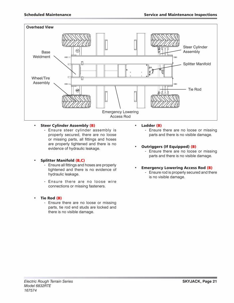
Wheel/Tire Assembly
Steer Cylinder Assembly
Tie Rod
Overhead View
Base Weldment
Splitter Manifold
Emergency Lowering Access Rod
SKYJACK, Page 21Electric Rough Terrain SeriesModel 6832RTE167574
Scheduled Maintenance Service and Maintenance Inspections
• Steer Cylinder Assembly (B) - Ensure steer cylinder assembly is
properly secured, there are no loose or missing parts, all fittings and hoses are properly tightened and there is no evidence of hydraulic leakage.
• Splitter Manifold (B,C) - Ensure all fittings and hoses are properly
tightened and there is no evidence of hydraulic leakage.
- Ensure there are no loose wire connections or missing fasteners.
• Tie Rod (B) - Ensure there are no loose or missing
parts, tie rod end studs are locked and there is no visible damage.
• Ladder (B) - Ensure there are no loose or missing
parts and there is no visible damage.
• Outriggers (If Equipped) (B) - Ensure there are no loose or missing
parts and there is no visible damage.
• Emergency Lowering Access Rod (B) - Ensure rod is properly secured and there
is no visible damage.
Wheel/Tire Assembly
Steer Cylinder Assembly
Tie Rod
Overhead View
Base Weldment
Splitter Manifold
Emergency Lowering Access Rod
Electric Rough Terrain SeriesModel 6832RTE
167574
SKYJACK, Page 22
Section 1 - Scheduled MaintenanceFunction Tests
1.2 Function TestsFunction tests are designed to discover any malfunctions before aerial platform is put into service. The operator must understand and follow step-by-step instructions to test all aerial platform functions.
WARNING
Never use a malfunctioning aerial plat-form. If malfunctions are discovered, aer-ial platform must be tagged and placed out of service. Repairs to aerial platform may only be made by a qualified service
technician.
After repairs are completed, operator must perform a pre-operation inspection and a series of function tests again before putting aerial platform into service.
Prior to performing function tests, be sure to read and understand the Start Operation section of the operating manual.
For function test that are to be run, please refer to the operating manual that corresponds to the correct serial number. Found there will be detailed instructions for which tests to perform, as well as how to properly and successfully perform them.
SKYJACK, Page 23Electric Rough Terrain SeriesModel 6832RTE167574
2
TablesTable 2.1 Specifications and Features .......................................................................................................................24Table 2.2 Floor Loading Pressure ..............................................................................................................................26Table 2.3 Maximum Platform Capacities (Evenly Distributed) ..................................................................................27Table 2.4 Fluids Table ................................................................................................................................................27Table 2.6 Torque Specifications for Fasteners (Imperial) ..........................................................................................29Table 2.8 Torque Specifications for Hydraulic Couplings & Hoses ...........................................................................31
Section 2MAINTENANCE TABLES AND DIAGRAMS
Table of Contents

Electric Rough Terrain SeriesModel 6832RTE
167574
SKYJACK, Page 24
Section 2 - Maintenance Tables and DiagramsService and Maintenance
Table 2.1 Specifications and Features
No Outriggers 7900 lb. 3585 kg
With Outriggers 8860 lb. 4020 kg
68” 1.73 m
No Outriggers 106.6” 2.71 m
With Outriggers 131.4” 3.34 m
56” x 99” 1.4 m x 2.5 m
Working 38 ft. 11.7 m
Platform Elevated 32 ft. 9.8 m
Platform Lowered 8.25 ft. 2.52 m
Drive 32 ft. 9.8 m
Normal Drive 4 mph 6.3 km/h
Elevated Drive 0.39 mph 0.63 km/h
Lift (Rated Load)
Lower (Rated Load)
Foam-filled
Air-filled
1120AA_ANSI
* Weights are approximate; refer to serial nameplate for specific weight.
6832RTE
OTR Outrigger - 26 x 12
N/A
Gradeability (Torque Equivalent To)
Tire
s
Model
Wei
ght
*
45%
Width
Leng
thH
eig
ht
Platform Size
39 sec
36 sec
Sp
eed
Tables

SKYJACK, Page 25Electric Rough Terrain SeriesModel 6832RTE167574
Section 2 - Maintenance Tables and Diagrams Service and Maintenance
Floor Loading Pressure
Locally Concentrated Pressure (LCP): Overall Uniform Pressure (OUP):
Foot Print Area = Tread Contact Area = πr2
Base Area = Length x Width
LCP = Maximum Wheel Load
Foot Print AreaOUP =
Weight of Aerial Platform + Capacity
Base Area
Length
WidthWidth
LengthLength
Length
Width
Diameter
WARNING
Do not use tires other than those specified for this machine. Do not mix different types of tires. Tires other than those specified can adversely affect stability. Failure to operate with matched, approved tires in good condition can result in death or serious injury. Replace tires with the exact, Skyjack-approved types only.
Electric Rough Terrain SeriesModel 6832RTE
167574
SKYJACK, Page 26
Section 2 - Maintenance Tables and DiagramsService and Maintenance
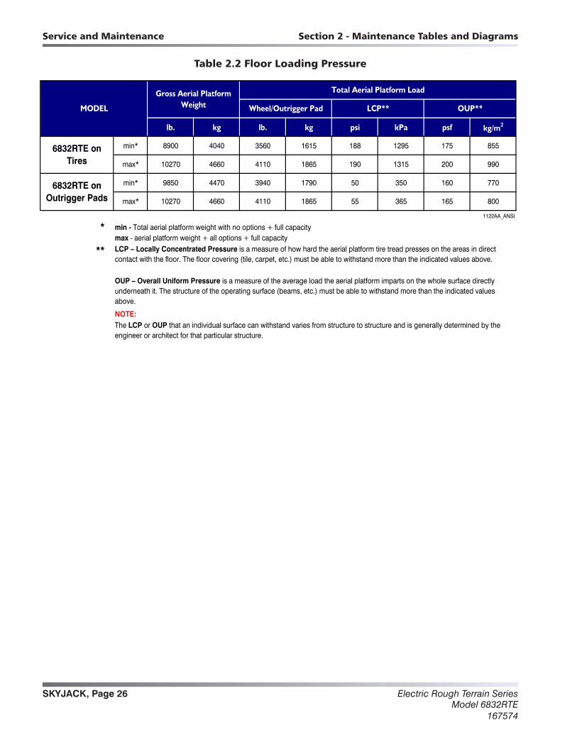
Table 2.2 Floor Loading Pressure
lb. kg lb. kg psi kPa psf kg/m2
min* 8900 4040 3560 1615 188 1295 175 855
max* 10270 4660 4110 1865 190 1315 200 990
min* 9850 4470 3940 1790 50 350 160 770
max* 10270 4660 4110 1865 55 365 165 800
1122AA_ANSI
*
**
NOTE:
6832RTE on Tires
min - Total aerial platform weight with no options + full capacitymax - aerial platform weight + all options + full capacity
Wheel/Outrigger Pad OUP**
The LCP or OUP that an individual surface can withstand varies from structure to structure and is generally determined by the engineer or architect for that particular structure.
LCP**MODEL
6832RTE onOutrigger Pads
Total Aerial Platform LoadGross Aerial Platform Weight
OUP – Overall Uniform Pressure is a measure of the average load the aerial platform imparts on the whole surface directly underneath it. The structure of the operating surface (beams, etc.) must be able to withstand more than the indicated values above.
LCP – Locally Concentrated Pressure is a measure of how hard the aerial platform tire tread presses on the areas in direct contact with the floor. The floor covering (tile, carpet, etc.) must be able to withstand more than the indicated values above.

SKYJACK, Page 27Electric Rough Terrain SeriesModel 6832RTE167574
Section 2 - Maintenance Tables and Diagrams Service and Maintenance
Table 2.3 Maximum Platform Capacities (Evenly Distributed)
Number of Occupants
Number of Occupants
6832RTEOne Extension
Platform1000 lb. 453 kg 4 300 lb. 136 kg 1 12.5 m/s 2.5 x 4.5
1121AA_ANSI
NOTE:
Maximum Wind Speed
Tilt Cutout Setting
(Degrees)
Occupants and materials are not to exceed rated load.Refer to capacity label for additional information and for models equipped with options.
MODELExtensionTotal
Capacity Capacity
Table 2.4 Fluids Table
Model Capacity (Liters) Capacity(US Gallons)
SJ68XXRT 86.88 22.95
60662AB
Oil Type
ATF Dexron
Shell Naturelle HF-E 32 (Bio oil)
III
Hydraulic Oil
AC
Electric Rough Terrain SeriesModel 6832RTE
167574
SKYJACK, Page 28
Section 2 - Maintenance Tables and DiagramsService and Maintenance
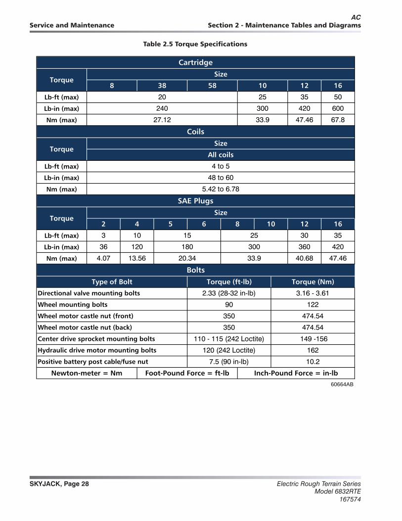
Table 2.5 Torque Specifications
Lb-ft (max)
Lb-in (max)
Nm (max)
Lb-ft (max)
Lb-in (max)
Nm (max)
Lb-ft (max)
Lb-in (max)
Nm (max)
Newton-meter = Nm Foot-Pound Force = ft-lb Inch-Pound Force = in-lb60664AB
Hydraulic drive motor mounting bolts 120 (242 Loctite) 162
Positive battery post cable/fuse nut 7.5 (90 in-lb) 10.2
Wheel motor castle nut (back) 350 474.54
Center drive sprocket mounting bolts 110 - 115 (242 Loctite) 149 -156
Wheel mounting bolts 90 122
Wheel motor castle nut (front) 350 474.54
Bolts
Type of Bolt Torque (ft-lb) Torque (Nm)
Directional valve mounting bolts 2.33 (28-32 in-lb) 3.16 - 3.61
4.07 13.56 20.34 33.9 40.68 47.46
36 120 180 300 360 420
8 10 12 16
3 10 15 25 30 35
4 to 5
48 to 60
5.42 to 6.78
SAE Plugs
TorqueSize
2 4 5 6
27.12 33.9 47.46 67.8
Coils
TorqueSize
All coils
20 25 35 50
240 300 420 600
Cartridge
TorqueSize
8 38 58 10 12 16
AC

SKYJACK, Page 29Electric Rough Terrain SeriesModel 6832RTE167574
Section 2 - Maintenance Tables and Diagrams Service and Maintenance
Table 2.6 Torque Specifications for Fasteners (Imperial)
Dry Lubed Dry Lubed Dry Lubed Dry Lubed Dry Lubed Dry Lubed
(in‐lb) (5) (4) (8) (6) (12) (9) ft‐lb 70 55 110 80 150 110
Nm 0.6 0.5 0.9 0.7 1.4 1.0 Nm 95 75 149 108 203 149
(in‐lb) (6) (5) (9) (7) (13) (10) ft‐lb 80 60 120 90 170 130
Nm 0.7 0.6 1.0 0.8 1.5 1.1 Nm 108 81 163 122 230 176
(in‐lb) (10) (8) (16) (12) (23) (17) ft‐lb 100 75 150 110 220 170
Nm 1.1 0.9 1.8 1.4 2.6 1.9 Nm 136 102 203 149 298 230
(in‐lb) (12) (9) (18) (13) (25) (19) ft‐lb 110 85 180 130 240 180
Nm 1.4 1.0 2.0 1.5 2.8 2.1 Nm 149 115 244 176 325 244
(in‐lb) (19) (14) (30) (22) (41) (31) ft‐lb 175 130 260 200 380 280
Nm 2.1 1.6 3.4 2.5 4.6 3.5 Nm 237 176 353 271 515 380
(in‐lb) (20) (15) (31) (23) (43) (32) ft‐lb 200 150 300 220 420 320
Nm 2.3 1.7 3.5 2.6 4.9 3.6 Nm 271 203 407 298 569 434
(in‐lb) (27) (21) (43) (32) (60) (45) ft‐lb 170 125 430 320 600 460
Nm 3.1 2.4 4.9 3.6 6.8 5.1 Nm 230 169 583 434 813 624
(in‐lb) (31) (23) (49) (36) (68) (51) ft‐lb 180 140 470 360 660 500
Nm 3.5 2.6 5.5 4.1 7.7 5.8 Nm 244 190 637 488 895 678
(in‐lb) / ft‐lb (66) (50) 8 (75) 12 9 ft‐lb 250 190 640 480 900 680
Nm 7.5 5.6 11 8.5 16 12 Nm 339 258 868 651 1220 922
(in‐lb) / ft‐lb (76) (56) 10 (86) 14 10 ft‐lb 270 210 710 530 1000 740
Nm 8.6 6.3 14 9.7 19 14 Nm 366 285 963 719 1356 1003
ft‐lb 11 8 17 13 25 18 ft‐lb 280 210 730 540 1020 760
Nm 15 11 23 18 34 24 Nm 380 285 990 732 1383 1030
ft‐lb 12 9 19 14 25 20 ft‐lb 350 270 800 600 1280 960
Nm 16 12 26 19 34 27 Nm 475 366 1085 813 1735 1302
ft‐lb 20 15 30 23 45 35 ft‐lb 400 300 880 660 1440 1080
Nm 27 20 41 31 61 47 Nm 542 407 1193 895 1952 1464
ft‐lb 23 17 35 25 50 35 ft‐lb 500 380 1120 840 1820 1360
Nm 31 23 47 34 68 47 Nm 678 515 1519 1139 2468 1844
ft‐lb 32 24 50 35 70 55 ft‐lb 550 420 1240 920 2000 1500
Nm 43 33 68 47 95 75 Nm 746 569 1681 1247 2712 2034
ft‐lb 36 27 55 40 80 60 ft‐lb 670 490 1460 1100 2380 1780
Nm 49 37 75 54 108 81 Nm 908 664 1979 1491 3227 2413
ft‐lb 50 35 75 55 110 80 ft‐lb 750 560 1680 1260 2720 2040
Nm 68 47 102 75 149 108 Nm 1017 759 2278 1708 3688 2766
ft‐lb 55 40 90 65 120 90 ft‐lb 870 650 1940 1460 3160 2360
Nm 75 54 122 88 163 122 Nm 1180 881 2630 1979 4284 3200
ft‐lb 980 730 2200 1640 3560 2660
Nm 1329 990 2983 2224 4827 3606
7/16-14
3/8-24
3/8-16
9/16-124-40
SAE 5
NOTE: Lubed includes lubricants such as lubrizing, oil, grease or uncured Loctite.
Inch‐Pound Force = in‐lb Foot‐Pound Force = ft‐lb Newton‐Meter = Nm
8-32
6-40
6-32
5/16-18
1/4-28
1/4-20
10-32
10-24
8-36
1/2-13
7/16-20
IMPERIAL BOLT TORQUE CHART
SizeTorque Type
SAE 2 SAE 5 SAE 8
5/8-11
9/16-18
7/8-9
3/4-16
4-48
1 1/8-12
1 1/8-75/16-24
3/4-10
5/8-18
1 1/2‐12
1 1/2‐6
IMPERIAL BOLT TORQUE CHART
Size Torque TypeSAE 2 SAE 8
1/2-20
1-14
1-12
1-8
7/8-14
1 3/8‐12
1 3/8‐6
1 1/4‐12
1 1/4-7
Electric Rough Terrain SeriesModel 6832RTE
167574
SKYJACK, Page 30
Section 2 - Maintenance Tables and DiagramsService and Maintenance
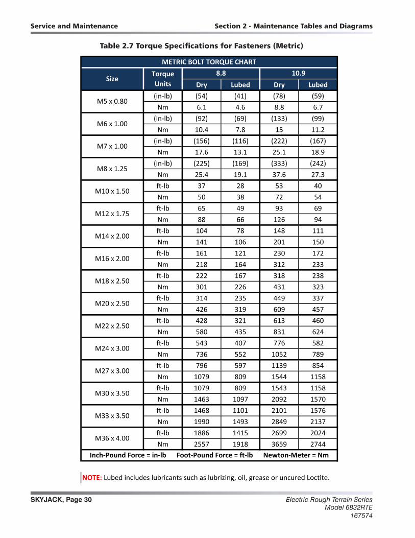
Table 2.7 Torque Specifications for Fasteners (Metric)
Dry Lubed Dry Lubed(in‐lb) (54) (41) (78) (59)Nm 6.1 4.6 8.8 6.7
(in‐lb) (92) (69) (133) (99)Nm 10.4 7.8 15 11.2
(in‐lb) (156) (116) (222) (167)Nm 17.6 13.1 25.1 18.9
(in‐lb) (225) (169) (333) (242)Nm 25.4 19.1 37.6 27.3ft‐lb 37 28 53 40Nm 50 38 72 54ft‐lb 65 49 93 69Nm 88 66 126 94ft‐lb 104 78 148 111Nm 141 106 201 150ft‐lb 161 121 230 172Nm 218 164 312 233ft‐lb 222 167 318 238Nm 301 226 431 323ft‐lb 314 235 449 337Nm 426 319 609 457ft‐lb 428 321 613 460Nm 580 435 831 624ft‐lb 543 407 776 582Nm 736 552 1052 789ft‐lb 796 597 1139 854Nm 1079 809 1544 1158ft‐lb 1079 809 1543 1158Nm 1463 1097 2092 1570ft‐lb 1468 1101 2101 1576Nm 1990 1493 2849 2137ft‐lb 1886 1415 2699 2024Nm 2557 1918 3659 2744
M18 x 2.50
M33 x 3.50
M36 x 4.00
10.9Torque Units
Size8.8
METRIC BOLT TORQUE CHART
M30 x 3.50
NOTE: Lubed includes lubricants such as lubrizing, oil, grease or uncured Loctite.
M20 x 2.50
M22 x 2.50
M24 x 3.00
M27 x 3.00
Inch‐Pound Force = in‐lb Foot‐Pound Force = ft‐lb Newton‐Meter = Nm
M5 x 0.80
M6 x 1.00
M7 x 1.00
M8 x 1.25
M10 x 1.50
M12 x 1.75
M14 x 2.00
M16 x 2.00
SKYJACK, Page 31Electric Rough Terrain SeriesModel 6832RTE167574
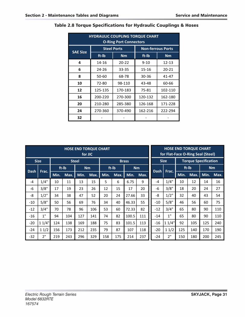
Section 2 - Maintenance Tables and Diagrams Service and Maintenance
ft‐lb Nm ft‐lb Nm
4 14‐16 20‐22 9‐10 12‐13
6 24‐26 33‐35 15‐16 20‐21
8 50‐60 68‐78 30‐36 41‐47
10 72‐80 98‐110 43‐48 60‐66
12 125‐135 170‐183 75‐81 102‐110
16 200‐220 270‐300 120‐132 162‐180
20 210‐280 285‐380 126‐168 171‐228
24 270‐360 370‐490 162‐216 222‐294
32 ‐ ‐ ‐ ‐
HYDRAULIC COUPLING TORQUE CHARTO‐Ring Port Connectors
SAE SizeSteel Ports Non‐ferrous Ports
Table 2.8 Torque Specifications for Hydraulic Couplings & Hoses
Min. Max. Min. Max. Min. Max. Min. Max.
‐4 1/4" 10 11 13 15 5 6 6.75 9
‐6 3/8" 17 19 23 26 12 15 17 20
‐8 1/2" 34 38 47 52 20 24 27.66 33
‐10 5/8" 50 56 69 76 34 40 46.33 55
‐12 3/4" 70 78 96 106 53 60 72.33 82
‐16 1" 94 104 127 141 74 82 100.5 111
‐20 1 1/4" 124 138 169 188 75 83 101.5 113
‐24 1 1/2 156 173 212 235 79 87 107 118
‐32 2" 219 243 296 329 158 175 214 237
Nm
HOSE END TORQUE CHARTfor JIC
Size Steel Brass
Dash Frac.ft‐lb Nm ft‐lb
Min. Max. Min. Max.
‐4 1/4" 10 12 14 16
‐6 3/8" 18 20 24 27
‐8 1/2" 32 40 43 54
‐10 5/8" 46 56 60 75
‐12 3/4" 65 80 90 110
‐14 1" 65 80 90 110
‐16 1 1/4" 92 105 125 240
‐20 1 1/2 125 140 170 190
‐24 2" 150 180 200 245
HOSE END TORQUE CHARTfor Flat‐Face O‐Ring Seal (Steel)
Size Torque Specification
Dash Frac.ft‐lb Nm
Electric Rough Terrain SeriesModel 6832RTE
167574
SKYJACK, Page 32
Notes
SKYJACK, Page 33Electric Rough Terrain SeriesModel 6832RTE167574
Charts3.1. Hydraulic Symbol Chart ......................................................................................................................................343.2. Electrical Symbol Chart ......................................................................................................................................353.3 AC Cord Color Code ............................................................................................................................................36
Parts List3.4 Hydraulic Schematic Parts List ............................................................................................................................373.5 Electrical Parts List ..............................................................................................................................................39
Diagrams and Schematics3.6 Hydraulic Schematic ............................................................................................................................................433.7 Main Manifold Component and Port Identification ..............................................................................................443.8 Splitter and Outrigger Manifolds Component and Port Identification .................................................................453.9 Control Box Wiring Diagram ................................................................................................................................463.10 Outrigger Control Box Wiring Diagram .............................................................................................................473.11 Scissor Arm Control Cable Wiring Diagram ......................................................................................................483.12 Main Manifold Harness Wiring Diagram ............................................................................................................493.13 Outrigger Harness Wiring Diagram ...................................................................................................................503.14 Motor Controller Electrical Schematic ...............................................................................................................513.15 Hybrid Power Pack Wiring .................................................................................................................................523.16a Electrical Panel Wiring Diagram – S/N 37300235 & above .............................................................................533.16b Electrical Panel Wiring Diagram – S/N 37300234 & below .............................................................................543.17a Electrical Schematic – No Options – S/N 37300235 & above ........................................................................553.17b Electrical Schematic – No Options – S/N 37300234 & below ........................................................................563.18a Electrical Schematic – All Options – S/N 37300235 & above ........................................................................573.18b Electrical Schematic – All Options – S/N 37300234 & below ........................................................................58
3
Section 3SYSTEM COMPONENT IDENTIFICATION AND SCHEMATICS
Table of Contents
Electric Rough Terrain SeriesModel 6832RTE
167574
SKYJACK, Page 34
Service and Maintenance Section 3 - System Component Identification and Schematics
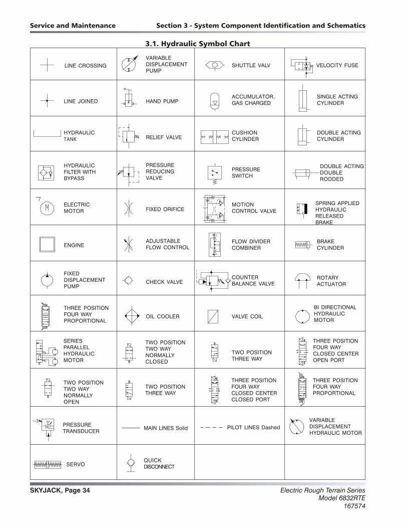
3.1. Hydraulic Symbol Chart
LINE CROSSINGVARIABLEDISPLACEMENTPUMP
SHUTTLE VALV VELOCITY FUSE
HAND PUMPLINE JOINEDACCUMULATOR,GAS CHARGED
SINGLE ACTINGCYLINDER
RELIEF VALVEHYDRAULICTANK
CUSHIONCYLINDER
DOUBLE ACTINGCYLINDER
PRESSUREREDUCINGVALVE
HYDRAULICFILTER WITHBYPASS
PRESSURESWITCH
DOUBLE ACTINGDOUBLERODDED
FIXED ORIFICEELECTRICMOTOR
MOTIONCONTROL VALVE
SPRING APPLIEDHYDRAULICRELEASEDBRAKE
ADJUSTABLEFLOW CONTROLENGINE
FLOW DIVIDERCOMBINER
BRAKECYLINDER
CHECK VALVE
FIXEDDISPLACEMENTPUMP
COUNTERBALANCE VALVE
ROTARYACTUATOR
OIL COOLER
THREE POSITIONFOUR WAYPROPORTIONAL
VALVE COIL
BI DIRECTIONALHYDRAULICMOTOR
TWO POSITIONTWO WAYNORMALLYCLOSED
SERIESPARALLELHYDRAULICMOTOR
TWO POSITIONTHREE WAY
THREE POSITIONFOUR WAYCLOSED CENTEROPEN PORT
TWO POSITIONTHREE WAY
TWO POSITIONTWO WAYNORMALLYOPEN
THREE POSITIONFOUR WAYCLOSED CENTERCLOSED PORT
THREE POSITIONFOUR WAYPROPORTIONAL
PRESSURETRANSDUCER MAIN LINES Solid PILOT LINES Dashed
VARIABLEDISPLACEMENTHYDRAULIC MOTOR
SERVOQUICKDISCONNECT
Charts
SKYJACK, Page 35Electric Rough Terrain SeriesModel 6832RTE167574
Section 3 - System Component Identification and Schematics Service and Maintenance
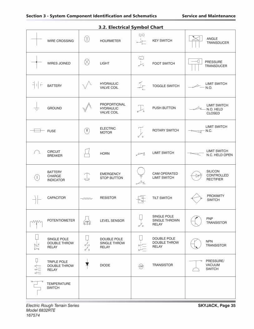
3.2. Electrical Symbol Chart
HOURMETER
LIGHT
HYDRAULIC VALVE COIL
PROPORTIONALHYDRAULIC VALVE COIL
ELECTRICMOTOR
HORN
EMERGENCYSTOP BUTTON
RESISTOR
LEVEL SENSOR
DOUBLE POLE SINGLE THROW RELAY
DIODE
WIRE CROSSING
WIRES JOINED
BATTERY
FUSE
GROUND
CIRCUITBREAKER
BATTERY CHARGEINDICATOR
CAPACITOR
POTENTIOMETER
SINGLE POLE DOUBLE THROW RELAY
TRIPLE POLE DOUBLE THROW RELAY
TEMPERATURE SWITCH
RELAY
RELAY
TRANSISTOR
DOUBLE POLE DOUBLE THROW
SINGLE POLESINGLE THROWN
TILT SWITCH
CAM OPERATED LIMIT SWITCH
LIMIT SWITCH
ROTARY SWITCH
PUSH BUTTON
TOGGLE SWITCH
FOOT SWITCH
KEY SWITCH ANGLETRANSDUCER
PRESSURETRANSDUCER
LIMIT SWITCHN.O.
LIMIT SWITCH N.O. HELD CLOSED
LIMIT SWITCH N.C.
LIMIT SWITCH N.C. HELD OPEN
SILICONCONTROLLEDRECTIFIER
PROXIMITY SWITCH
PNPTRANSISTOR
NPNTRANSISTOR
PRESSURE/VACUUM SWITCH
Electric Rough Terrain SeriesModel 6832RTE
167574
SKYJACK, Page 36
Service and Maintenance Section 3 - System Component Identification and Schematics
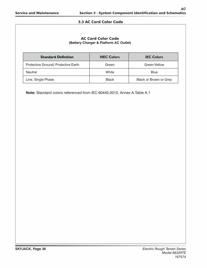
Standard Definition NEC Colors IEC Colors
Protective Ground/ Protective Earth Green Green-Yellow
Neutral White Blue
Line, Single Phase Black Black or Brown or Grey
3.3 AC Cord Color Code
AC Cord Color Code(Battery Charger & Platform AC Outlet)
Note: Standard colors referenced from IEC 60445:2010, Annex A:Table A.1
AC
SKYJACK, Page 37Electric Rough Terrain SeriesModel 6832RTE167574
Section 3 - System Component Identification and Schematics Service and Maintenance
Index No.
Skyjack Part No.
Qty. Description
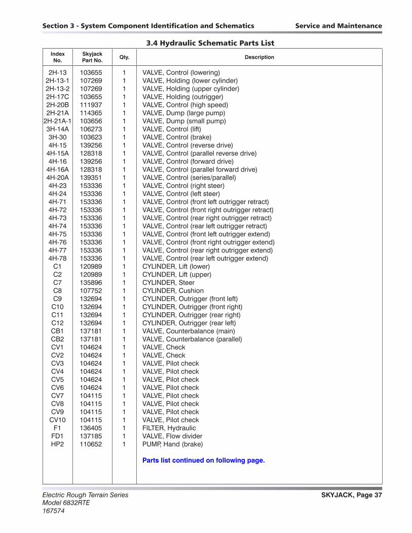
3.4 Hydraulic Schematic Parts List
2H-13 103655 1 VALVE, Control (lowering) 2H-13-1 107269 1 VALVE, Holding (lower cylinder) 2H-13-2 107269 1 VALVE, Holding (upper cylinder) 2H-17C 103655 1 VALVE, Holding (outrigger) 2H-20B 111937 1 VALVE, Control (high speed) 2H-21A 114365 1 VALVE, Dump (large pump) 2H-21A-1 103656 1 VALVE, Dump (small pump) 3H-14A 106273 1 VALVE, Control (lift) 3H-30 103623 1 VALVE, Control (brake) 4H-15 139256 1 VALVE, Control (reverse drive) 4H-15A 128318 1 VALVE, Control (parallel reverse drive) 4H-16 139256 1 VALVE, Control (forward drive) 4H-16A 128318 1 VALVE, Control (parallel forward drive) 4H-20A 139351 1 VALVE, Control (series/parallel) 4H-23 153336 1 VALVE, Control (right steer) 4H-24 153336 1 VALVE, Control (left steer) 4H-71 153336 1 VALVE, Control (front left outrigger retract) 4H-72 153336 1 VALVE, Control (front right outrigger retract) 4H-73 153336 1 VALVE, Control (rear right outrigger retract) 4H-74 153336 1 VALVE, Control (rear left outrigger retract) 4H-75 153336 1 VALVE, Control (front left outrigger extend) 4H-76 153336 1 VALVE, Control (front right outrigger extend) 4H-77 153336 1 VALVE, Control (rear right outrigger extend) 4H-78 153336 1 VALVE, Control (rear left outrigger extend) C1 120989 1 CYLINDER, Lift (lower) C2 120989 1 CYLINDER, Lift (upper) C7 135896 1 CYLINDER, Steer C8 107752 1 CYLINDER, Cushion C9 132694 1 CYLINDER, Outrigger (front left) C10 132694 1 CYLINDER, Outrigger (front right) C11 132694 1 CYLINDER, Outrigger (rear right) C12 132694 1 CYLINDER, Outrigger (rear left) CB1 137181 1 VALVE, Counterbalance (main) CB2 137181 1 VALVE, Counterbalance (parallel) CV1 104624 1 VALVE, Check CV2 104624 1 VALVE, Check CV3 104624 1 VALVE, Pilot check CV4 104624 1 VALVE, Pilot check CV5 104624 1 VALVE, Pilot check CV6 104624 1 VALVE, Pilot check CV7 104115 1 VALVE, Pilot check CV8 104115 1 VALVE, Pilot check CV9 104115 1 VALVE, Pilot check CV10 104115 1 VALVE, Pilot check F1 136405 1 FILTER, Hydraulic FD1 137185 1 VALVE, Flow divider HP2 110652 1 PUMP, Hand (brake)
Parts list continued on following page.
Parts List

Electric Rough Terrain SeriesModel 6832RTE
167574
SKYJACK, Page 38
Service and Maintenance Section 3 - System Component Identification and Schematics
Index No.
Skyjack Part No.
Qty. Description
3.4 Hydraulic Schematic Parts List (Continued)
Parts list continued from previous page.
MI 137479 1 MOTOR, Wheel (front left) M2 137479 1 MOTOR, Wheel (front right) M3 137480 1 MOTOR, Wheel (rear right) M4 137480 1 MOTOR, Wheel (rear left) MB1 137125 1 BLOCK, Manifold (main) MB3 106688 1 BLOCK, Manifold (lower holding valve) MB4 108778 1 BLOCK, Manifold (upper holding valve) MB5 139830 1 BLOCK, Manifold (sandwich) MB6 139450 1 BLOCK, Manifold (splitter) MB8 111970 1 BLOCK, Manifold (outrigger) O1 105281 1 ORIFICE, 0.067 diameter (holding valve) O2 137509 1 ORIFICE, 0.089 diameter (lowering) O3 137509 1 ORIFICE, 0.089 diameter (lowering) O4 139679 1 ORIFICE, 0.055 diameter (steering) O5 137508 1 ORIFICE, 0.028 diameter (brake) P1 114201 1 PUMP, Dual hydraulic (0.671/ 0.366) R1 104534 1 VALVE, Relief (system) R2 104534 1 VALVE, Relief (lift) R3 106557 1 VALVE, Relief (lift cylinder) R4 106557 1 VALVE, Relief (lift cylinder) R5 139683 1 VALVE, Relief (drive) V1 107271 1 VALVE, Pull (emergency lowering) V2 137182 1 VALVE, Freewheel V6 113752 1 VALVE, Auto reset (brake)
SKYJACK, Page 39Electric Rough Terrain SeriesModel 6832RTE167574
Section 3 - System Component Identification and Schematics Service and Maintenance
Index No.
Skyjack Part No.
Qty. Description
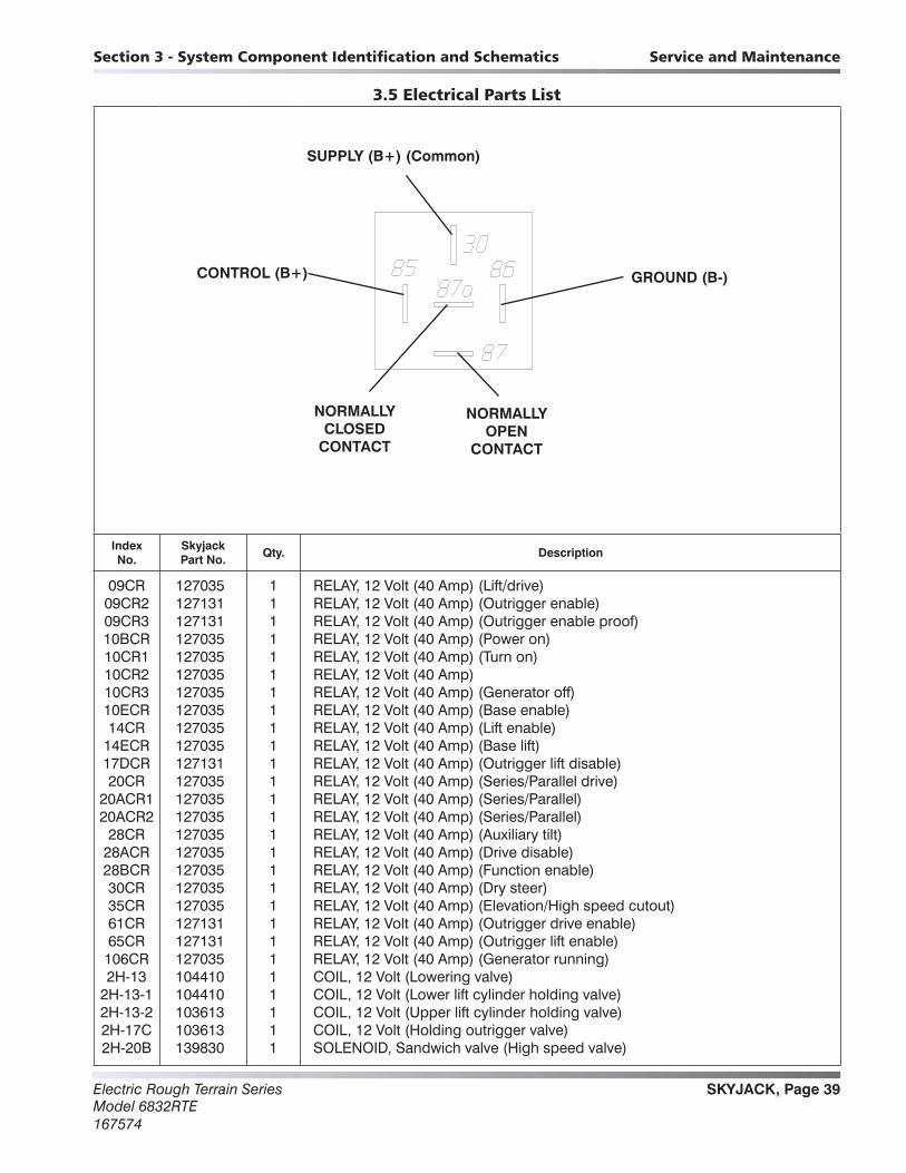
3.5 Electrical Parts List
09CR 127035 1 RELAY, 12 Volt (40 Amp) (Lift/drive) 09CR2 127131 1 RELAY, 12 Volt (40 Amp) (Outrigger enable) 09CR3 127131 1 RELAY, 12 Volt (40 Amp) (Outrigger enable proof) 10BCR 127035 1 RELAY, 12 Volt (40 Amp) (Power on) 10CR1 127035 1 RELAY, 12 Volt (40 Amp) (Turn on) 10CR2 127035 1 RELAY, 12 Volt (40 Amp) 10CR3 127035 1 RELAY, 12 Volt (40 Amp) (Generator off) 10ECR 127035 1 RELAY, 12 Volt (40 Amp) (Base enable) 14CR 127035 1 RELAY, 12 Volt (40 Amp) (Lift enable) 14ECR 127035 1 RELAY, 12 Volt (40 Amp) (Base lift) 17DCR 127131 1 RELAY, 12 Volt (40 Amp) (Outrigger lift disable) 20CR 127035 1 RELAY, 12 Volt (40 Amp) (Series/Parallel drive) 20ACR1 127035 1 RELAY, 12 Volt (40 Amp) (Series/Parallel) 20ACR2 127035 1 RELAY, 12 Volt (40 Amp) (Series/Parallel) 28CR 127035 1 RELAY, 12 Volt (40 Amp) (Auxiliary tilt) 28ACR 127035 1 RELAY, 12 Volt (40 Amp) (Drive disable) 28BCR 127035 1 RELAY, 12 Volt (40 Amp) (Function enable) 30CR 127035 1 RELAY, 12 Volt (40 Amp) (Dry steer) 35CR 127035 1 RELAY, 12 Volt (40 Amp) (Elevation/High speed cutout) 61CR 127131 1 RELAY, 12 Volt (40 Amp) (Outrigger drive enable) 65CR 127131 1 RELAY, 12 Volt (40 Amp) (Outrigger lift enable) 106CR 127035 1 RELAY, 12 Volt (40 Amp) (Generator running) 2H-13 104410 1 COIL, 12 Volt (Lowering valve) 2H-13-1 104410 1 COIL, 12 Volt (Lower lift cylinder holding valve) 2H-13-2 103613 1 COIL, 12 Volt (Upper lift cylinder holding valve) 2H-17C 103613 1 COIL, 12 Volt (Holding outrigger valve) 2H-20B 139830 1 SOLENOID, Sandwich valve (High speed valve)
CONTROL (B+)
NORMALLYCLOSED
CONTACT
SUPPLY (B+) (Common)
GROUND (B-)
NORMALLYOPEN
CONTACT
Electric Rough Terrain SeriesModel 6832RTE
167574
SKYJACK, Page 40
Service and Maintenance Section 3 - System Component Identification and Schematics
Index No.
Skyjack Part No.
Qty. Description
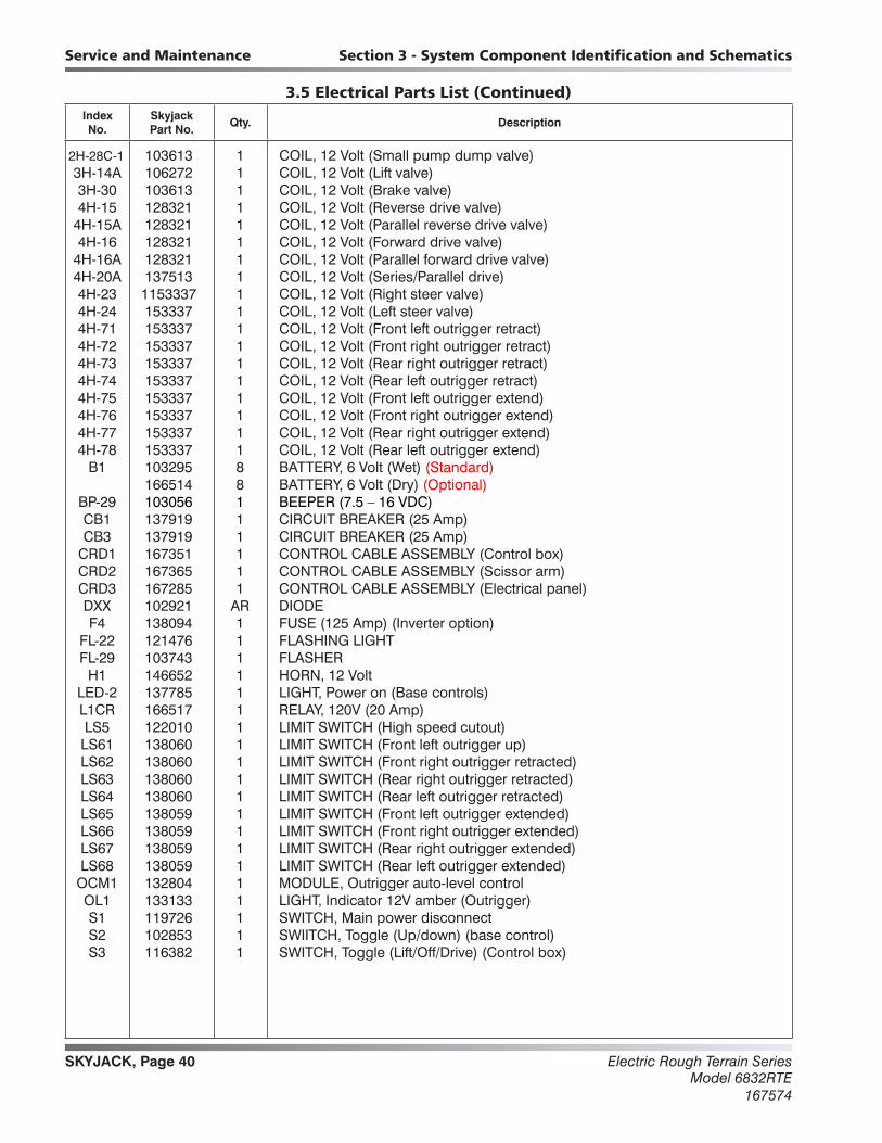
3.5 Electrical Parts List (Continued)
2H-28C-1 103613 1 COIL, 12 Volt (Small pump dump valve) 3H-14A 106272 1 COIL, 12 Volt (Lift valve) 3H-30 103613 1 COIL, 12 Volt (Brake valve) 4H-15 128321 1 COIL, 12 Volt (Reverse drive valve) 4H-15A 128321 1 COIL, 12 Volt (Parallel reverse drive valve) 4H-16 128321 1 COIL, 12 Volt (Forward drive valve) 4H-16A 128321 1 COIL, 12 Volt (Parallel forward drive valve) 4H-20A 137513 1 COIL, 12 Volt (Series/Parallel drive) 4H-23 1153337 1 COIL, 12 Volt (Right steer valve) 4H-24 153337 1 COIL, 12 Volt (Left steer valve) 4H-71 153337 1 COIL, 12 Volt (Front left outrigger retract) 4H-72 153337 1 COIL, 12 Volt (Front right outrigger retract) 4H-73 153337 1 COIL, 12 Volt (Rear right outrigger retract) 4H-74 153337 1 COIL, 12 Volt (Rear left outrigger retract) 4H-75 153337 1 COIL, 12 Volt (Front left outrigger extend) 4H-76 153337 1 COIL, 12 Volt (Front right outrigger extend) 4H-77 153337 1 COIL, 12 Volt (Rear right outrigger extend) 4H-78 153337 1 COIL, 12 Volt (Rear left outrigger extend) B1 103295 8 BATTERY, 6 Volt (Wet) (Standard) 166514 8 BATTERY, 6 Volt (Dry) (Optional) BP-29 103056 1 BEEPER (7.5 – 16 VDC) CB1 137919 1 CIRCUIT BREAKER (25 Amp) CB3 137919 1 CIRCUIT BREAKER (25 Amp) CRD1 167351 1 CONTROL CABLE ASSEMBLY (Control box) CRD2 167365 1 CONTROL CABLE ASSEMBLY (Scissor arm) CRD3 167285 1 CONTROL CABLE ASSEMBLY (Electrical panel) DXX 102921 AR DIODE F4 138094 1 FUSE (125 Amp) (Inverter option) FL-22 121476 1 FLASHING LIGHT FL-29 103743 1 FLASHER H1 146652 1 HORN, 12 Volt LED-2 137785 1 LIGHT, Power on (Base controls) L1CR 166517 1 RELAY, 120V (20 Amp) LS5 122010 1 LIMIT SWITCH (High speed cutout) LS61 138060 1 LIMIT SWITCH (Front left outrigger up) LS62 138060 1 LIMIT SWITCH (Front right outrigger retracted) LS63 138060 1 LIMIT SWITCH (Rear right outrigger retracted) LS64 138060 1 LIMIT SWITCH (Rear left outrigger retracted) LS65 138059 1 LIMIT SWITCH (Front left outrigger extended) LS66 138059 1 LIMIT SWITCH (Front right outrigger extended) LS67 138059 1 LIMIT SWITCH (Rear right outrigger extended) LS68 138059 1 LIMIT SWITCH (Rear left outrigger extended) OCM1 132804 1 MODULE, Outrigger auto-level control OL1 133133 1 LIGHT, Indicator 12V amber (Outrigger) S1 119726 1 SWITCH, Main power disconnect S2 102853 1 SWIITCH, Toggle (Up/down) (base control) S3 116382 1 SWITCH, Toggle (Lift/Off/Drive) (Control box)
SKYJACK, Page 41Electric Rough Terrain SeriesModel 6832RTE167574
Section 3 - System Component Identification and Schematics Service and Maintenance
Index No.
Skyjack Part No.
Qty. Description
3.5 Electrical Parts List (Continued)
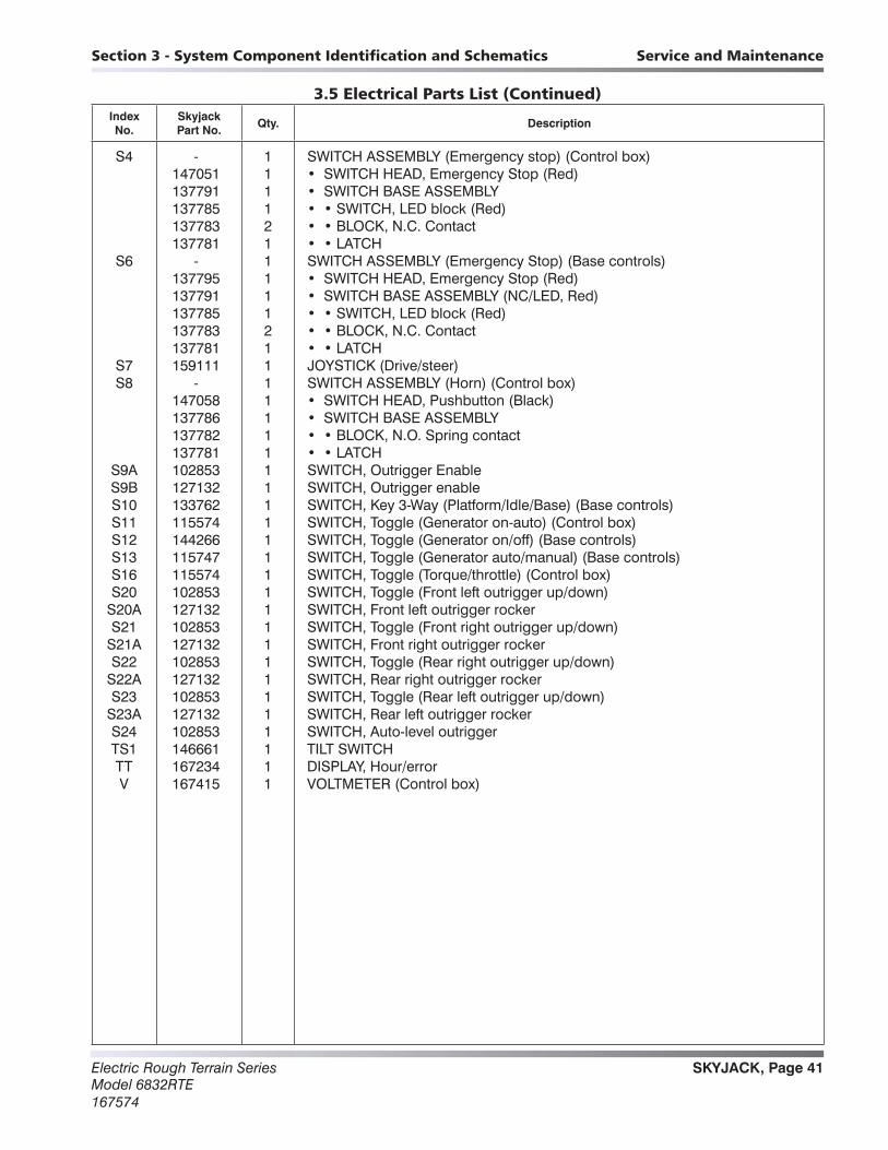
S4 - 1 SWITCH ASSEMBLY (Emergency stop) (Control box) 147051 1 • SWITCH HEAD, Emergency Stop (Red) 137791 1 • SWITCH BASE ASSEMBLY 137785 1 • • SWITCH, LED block (Red) 137783 2 • • BLOCK, N.C. Contact 137781 1 • • LATCH S6 - 1 SWITCH ASSEMBLY (Emergency Stop) (Base controls) 137795 1 • SWITCH HEAD, Emergency Stop (Red) 137791 1 • SWITCH BASE ASSEMBLY (NC/LED, Red) 137785 1 • • SWITCH, LED block (Red) 137783 2 • • BLOCK, N.C. Contact 137781 1 • • LATCH S7 159111 1 JOYSTICK (Drive/steer) S8 - 1 SWITCH ASSEMBLY (Horn) (Control box) 147058 1 • SWITCH HEAD, Pushbutton (Black) 137786 1 • SWITCH BASE ASSEMBLY 137782 1 • • BLOCK, N.O. Spring contact 137781 1 • • LATCH S9A 102853 1 SWITCH, Outrigger Enable S9B 127132 1 SWITCH, Outrigger enable S10 133762 1 SWITCH, Key 3-Way (Platform/Idle/Base) (Base controls) S11 115574 1 SWITCH, Toggle (Generator on-auto) (Control box) S12 144266 1 SWITCH, Toggle (Generator on/off) (Base controls) S13 115747 1 SWITCH, Toggle (Generator auto/manual) (Base controls) S16 115574 1 SWITCH, Toggle (Torque/throttle) (Control box) S20 102853 1 SWITCH, Toggle (Front left outrigger up/down) S20A 127132 1 SWITCH, Front left outrigger rocker S21 102853 1 SWITCH, Toggle (Front right outrigger up/down) S21A 127132 1 SWITCH, Front right outrigger rocker S22 102853 1 SWITCH, Toggle (Rear right outrigger up/down) S22A 127132 1 SWITCH, Rear right outrigger rocker S23 102853 1 SWITCH, Toggle (Rear left outrigger up/down) S23A 127132 1 SWITCH, Rear left outrigger rocker S24 102853 1 SWITCH, Auto-level outrigger TS1 146661 1 TILT SWITCH TT 167234 1 DISPLAY, Hour/error V 167415 1 VOLTMETER (Control box)

Electric Rough Terrain SeriesModel 6832RTE
167574
SKYJACK, Page 42
Notes
SKYJACK, Page 43Electric Rough Terrain SeriesModel 6832RTE167574
A B C D E F G H
V
Z
Y
X
W
M167693AC
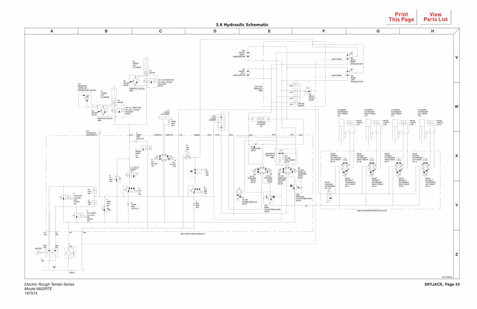
3.6 Hydraulic Schematic
SANDWICH MANIFOLD
MB5
04STEERINGORIFICEØ0.055
03LOWERINGORIFICEØ0.089 68 32 RT
02LOWERINGORIFICEØ0.089 68 32 RT
CV3
R5DRIVERELIEFVALVE
M4REAR LEFTWHEELMOTOR
M3REAR RIGHTWHEELMOTOR
SPLITTER MANIFOLD
MB6
CASE DRAIN
M1FRONT
LEFTWHEELMOTOR
M2FRONT RIGHT
WHEELMOTOR
T-A
FD-CFD-BFD-A M-DM-CM-BM-ABRAKEP-CSTEER-BSTEER-ALIFT
SMPUMP
LRGPUMP
DRAINTANK
A B
TPS54H-23RIGHT STEERVALVE
DIVIDERFLOW
FD1
MB8 OUTRIGGER MANIFOLD BLOCK
CYLINDEROUTRIGGERLEFT REARC12
VALVECHECKCV10
CYLINDEROUTRIGGERRIGHT REARC11
VALVECHECKCV9
CYLINDEROUTRIGGERRIGHT FRONTC10
VALVECHECKCV8
CYLINDEROUTRIGGERLEFT FRONTC9
VALVECHECKCV7
VALVERETRACTOUTRIGGERLEFT REAR4H-74
VALVERETRACTOUTRIGGERRIGHT REAR4H-73
VALVERETRACTOUTRIGGERRIGHT FRONT4H-72
VALVERETRACTOUTRIGGERLEFT FRONT4H-71
VALVEHOLDINGOUTRIGGER2H-17C
VALVEEXTENDOUTRIGGERLEFT REAR4H-78
VALVEEXTENDOUTRIGGERRIGHT REAR4H-77
VALVEEXTENDOUTRIGGERRIGHT FRONT4H-76
VALVEEXTENDOUTRIGGERLEFT FRONT4H-75
MB1 68XXRT MAIN MANIFOLD
05BRAKEORIFICEØ0.028
2H-13-2 (ANSI/CSA)2H-13B-2 (CE/AS)HOLDINGVALVE
C2UPPERLIFTCYLINDER
R4RELIEFVALVE
C1LOWERLIFTCYLINDER
O1Ø0.067
PT1PRESSUREOVERLOADTRANSDUCER (CE/AS)
MOTOR
P1PUMP
RESERVOIR
F1FILTER
CV2CHECK VALVE
CV1CHECK VALVE
C7STEER
CYLINDER
S22H-21A-1 (ANSI/CSA)2H-21B-1 (CE/AS)SMALLPUMP DUMPVALVE
R1SYSTEMRELIEFVALVE
2H-13-1 (ANSI/CSA)2H-13B-1 (CE/AS)HOLDINGVALVE
R3RELIEFVALVE
R2LIFTRELIEFVALVE
S43H-14ALIFTVALVE
P-AHYDRAULICDISCONNECT
CB2PARALLELCOUNTERBALANCEVALVE
CB1MAINCOUNTERBALANCEVALVE
S84H-15
REVERSE DRIVE VALVE
HP2HANDPUMP
V6AUTORESETVALVE
V1EMERGENCYLOWERINGPULLVALVE
S63H-30BRAKEVALVE
S74H-20ASERIES/PARALLELVALVE
V2FREEWHEELVALVE
LARGEPUMP
SMALLPUMP
S12H-21A (ANSI/CSA)2H-21B (CE/AS)LARGEPUMP DUMPVALVE
S84H-16
FORWARD DRIVE VALVE
S94H-15APARALLELREVERSE DRIVE VALVE
S94H-16APARALLELFORWARD DRIVE VALVE
O1Ø0.067
CASE DRAIN
P
T B
A
T B
AP A
BT
P P
T B
AB
TP
AA
P T
B
MANIFOLD BLOCKMB4
MANIFOLD BLOCKMB3
CV4
CV5
CV6
CUSHIONCYLINDER
C8
CHECKVALVES
S102H-20BHIGH SPEED VALVE
S54H-24
LEFT STEERVALVE
M
2H-13 (ANSI/CSA)2H-13B (CE/AS)LOWERINGVALVE
Diagrams and Schematics

Electric Rough Terrain SeriesModel 6832RTE
167574
SKYJACK, Page 44
A B C D E F G H
V
Z
Y
X
W
3.7 Main Manifold Component and Port Identification
V2FREEWHEEL
VALVE
HP2HANDPUMP
V6AUTORESETVALVE
V1EMERGENCYLOWERING
PULLVALVE
S43H-14A
LIFTVALVE
S54H-23
RIGHT STEERVALVE
S54H-24
LEFTSTEERVALVE
R1SYSTEMRELIEFVALVE
S84H-16A
FORWARDDRIVEVALVE
S12H-17A (ANSI/CSA)
2H-17B (CE)LARGE
PUMP DUMPVALVE
S84H-15A
REVERSEDRIVEVALVE
CV2CHECKVALVE
CV1CHECKVALVE
CB1MAIN
COUNTERBALANCEVALVE
CB2PARALLEL
COUNTERBALANCEVALVE
S63H-30DBRAKEVALVE
S32H-13(ANSI/CSA)
2H13B(CE)LOWERING
VALVE
S74H-20A
SERIES/PARALLELVALVE
O4BRAKE ORIFICE
S94H-15B
PARALLELREVERSE
DRIVEVALVE
S102H-20BHIGH
SPEEDVALVE
S94H-16B
PARALLELFORWARD
DRIVEVALVE
TOSTEER
CYLINDER
TOLIFT
CYLINDER
TOSMALLPUMP
TOLARGEPUMP
R2LIFT
RELIEFVALVE
TO TANK
TODRAIN
TOBRAKE
S22H-18B (ANSI/CSA)
2H-18C (CE)SMALL
PUMP DUMPVALVE
MAIN MANIFOLD
AC
M138189AP_3C

SKYJACK, Page 45Electric Rough Terrain SeriesModel 6832RTE167574
A B C D E F G H
V
Z
Y
X
W
3.8 Splitter and Outrigger Manifolds Component and Port Identification
M138075AE, M138045AB_1
SPLITTER MANIFOLD
R5DRIVERELIEFDRIVE
CV3CHECKVALVE
CV5CHECKVALVE
CV6CHECKVALVE
CV4CHECKVALVE
OUTRIGGERCYLINDER
4H-71AOUTRIGGERLEFT FRONT
RETRACT
4H-74AOUTRIGGERLEFT REARRETRACT
4H-73AOUTRIGGERRIGHT REAR
RETRACT
4H-72AOUTRIGGER
RIGHT FRONTRETRACT
4H-78AOUTRIGGERLEFT REAR
EXTEND
4H-75AOUTRIGGERLEFT FRONT
EXTEND
4H-77AOUTRIGGERRIGHT REAR
EXTEND
4H-76AOUTRIGGER
RIGHT FRONTEXTEND
2H-17COUTRIGGER
HOLDINGVALVE
OUTRIGGER MANIFOLD

Electric Rough Terrain SeriesModel 6832RTE
167574
SKYJACK, Page 46
A B C D E F G H
V
Z
Y
X
W
3.9 Control Box Wiring Diagram
M167350AA
S3 - LIFT/OFF/DRIVE
S16 - TORQUE
S4 - EMERGENCY STOP
S8 - HORN
LED-1
S13 - GENERATOR ENABLE
119
106
75
48
32
1
2321
2219
1718
2015
1413
162412
MALEBACK VIEW
CRD1
RED BLACK WHITE (85)ORANGE GREEN (60)GREEN (49)GREEN WHITE (B-)GREEN BLACK (3B)RED WHITE (85A)BLUE BLACK (24)BLACK WHITE (23)BLACK WHITE RED (20)ORANGE BLACK (59)RED BLACK (19)WHITE BLACK (16)
(15) BLUE(14) BLACK
(13) ORANGE(10) BLUE RED
(10) BLUE WHITE(09) ORANGE RED
(08) BLACK RED(07) RED GREEN
(07) RED(05) WHITE BLACK RED
(05) WHITE RED(02) WHITE
A
9 PIN CONNECTOR SUB-ASSEMBLY
188A
15
13
PIN # - FUNCTIONPIN 1 - LEFTPIN 2 - STEERING VS+PIN 3 - RIGHTPIN 4 - FWD/UPPIN 5 - JOYSTICK VS+PIN 6 - REV/DOWNPIN 7 - PWMPIN 8 - GNDPIN 9 - ENABLE VS+
CTRL BOX HARNESS24 BLUE/BLACK12B BROWN/RED23 BLACK/WHITEB RED08 BLUEA PURPLE/WHITE59 ORANGE/BLACK02 WHITE8A BLUE
JOYSTICK HARNESSWHITE/REDWHITE/GREENWHITEYELLOWREDGREYBLUEBLACKWHITE/ BLUE
CTRL BOX
JOYSTICK HARNESS
HARNESS
16
14
12B
8B0808
49
07 0808
W1
W2
10
07
6002
1005
05
02
X2X1
W9
12B
8B
08
09
85
85A
B08
19
19
W3
W8
W5
W7
W6
W4
SKYJACK, Page 47Electric Rough Terrain SeriesModel 6832RTE167574
A B C D E F G H
V
Z
Y
X
W
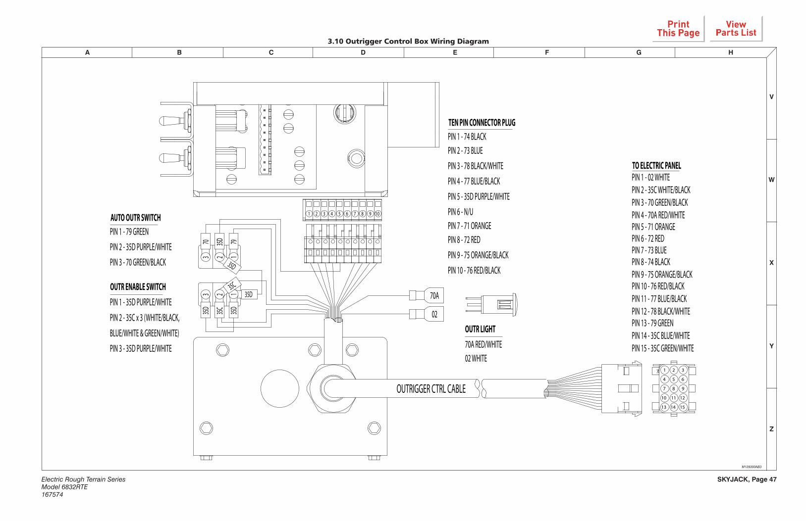
3.10 Outrigger Control Box Wiring Diagram
M129300AB3
OUTR ENABLE SWITCHPIN 1 - 35D PURPLE/WHITE
PIN 2 - 35C x 3 (WHITE/BLACK,
BLUE/WHITE & GREEN/WHITE)
PIN 3 - 35D PURPLE/WHITE
AUTO OUTR SWITCHPIN 1 - 79 GREEN
PIN 2 - 35D PURPLE/WHITE
PIN 3 - 70 GREEN/BLACK
35D
35D3
3
35C
35D
35D
22
11
70 35D 79
OUTR LIGHT70A RED/WHITE02 WHITE
OUTRIGGER CTRL CABLE
TEN PIN CONNECTOR PLUGPIN 1 - 74 BLACKPIN 2 - 73 BLUE
PIN 3 - 78 BLACK/WHITE
PIN 4 - 77 BLUE/BLACK
PIN 5 - 35D PURPLE/WHITE
PIN 6 - N/UPIN 7 - 71 ORANGEPIN 8 - 72 RED
PIN 9 - 75 ORANGE/BLACK
PIN 10 - 76 RED/BLACK
02
70A
35C
TO ELECTRIC PANELPIN 1 - 02 WHITEPIN 2 - 35C WHITE/BLACKPIN 3 - 70 GREEN/BLACKPIN 4 - 70A RED/WHITEPIN 5 - 71 ORANGEPIN 6 - 72 REDPIN 7 - 73 BLUEPIN 8 - 74 BLACKPIN 9 - 75 ORANGE/BLACKPIN 10 - 76 RED/BLACKPIN 11 - 77 BLUE/BLACKPIN 12 - 78 BLACK/WHITEPIN 13 - 79 GREENPIN 14 - 35C BLUE/WHITEPIN 15 - 35C GREEN/WHITE
3
6
1
4 5
2
9
12
7
10 11
8
1513 14
1098765321 4

Electric Rough Terrain SeriesModel 6832RTE
167574
SKYJACK, Page 48
A B C D E F G H
V
Z
Y
X
W
INSERT ORIENTATION FRONT VIEW INSERT 1-24
PIN 1 - WHITE (02)PIN 2 - WHITE RED (05)PIN 3 - WHITE BLACK RED (05)PIN 4 - RED (07)PIN 5 - RED GREEN (07)PIN 6 - BLACK RED (08)PIN 7 - ORANGE RED (09)PIN 8 - BLUE WHITE (10)PIN 9 - BLUE RED (10)PIN 10 - ORANGE (13)PIN 11 - BLACK (14)PIN 12 - BLUE (15)PIN 13 - WHITE BLACK (16)PIN 14 - RED BLACK (19)PIN 15 - ORANGE BLACK (59)PIN 16 - BLACK WHITE RED (20)PIN 17 - BLACK WHITE (23)PIN 18 - BLUE BLACK (24)PIN 19 - RED WHITE (85A)PIN 20 - GREEN BLACK (3B)PIN 21 - GREEN WHITE (B-)PIN 22 - GREEN (49)PIN 23 - ORANGE GREEN (60)PIN 24 - RED BLACK WHITE (85)
3.11 Scissor Arm Control Cable Wiring Diagram
M167365AA_1
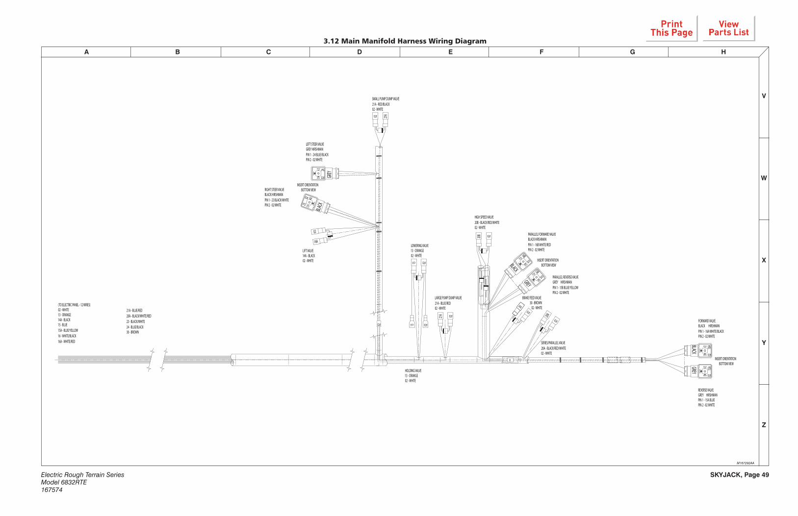
SKYJACK, Page 49Electric Rough Terrain SeriesModel 6832RTE167574
A B C D E F G H
V
Z
Y
X
W
02
02
2402
LIFT VALVE14A - BLACK02 - WHITE
INSERT ORIENTATIONBOTTOM VIEW
LEFT STEER VALVEGREY HIRSHMANPIN 1 - 24 BLUE/BLACKPIN 2 - 02 WHITE
RIGHT STEER VALVEBLACK HIRSHMANPIN 1 - 23 BLACK/WHITEPIN 2 - 02 WHITE
02
14A
02
0223
02
02
21A - BLUE/RED20A - BLACK/WHITE/RED23 - BLACK/WHITE24 - BLUE/BLACK30 - BROWN
(TO ELECTRIC PANEL - 12 WIRES)02 - WHITE13 - ORANGE14A - BLACK15 - BLUE15A - BLUE/YELLOW16 - WHITE/BLACK16A - WHITE/RED
15A02
0216A
02
20A
FORWARD VALVEBLACK HIRSHMANPIN 1 - 16A WHITE/BLACKPIN 2 - 02 WHITE
INSERT ORIENTATIONBOTTOM VIEW
REVERSE VALVEGREY HIRSHMANPIN 1 - 15A BLUEPIN 2 - 02 WHITE
SERIES/PARALLEL VALVE20A - BLACK/RED/WHITE02 - WHITE
SMALL PUMP DUMP VALVE21A - RED/BLACK 02 - WHITE
21A
LOWERING VALVE13 - ORANGE02 - WHITE
LARGE PUMP DUMP VALVE21A - BLUE/RED02 - WHITE
21A
1313
HOLDING VALVE13 - ORANGE02 - WHITE
30
02
BRAKE FEED VALVE30 - BROWN
02 - WHITE
16B02
0215B
20B 02
HIGH SPEED VALVE20B - BLACK/RED/WHITE02 - WHITE
PARALLEL FORWARD VALVEBLACK HIRSHMANPIN 1 - 16B WHITE/REDPIN 2 - 02 WHITE
INSERT ORIENTATIONBOTTOM VIEW
PARALLEL REVERSE VALVEGREY HIRSHMANPIN 1 - 15B BLUE/YELLOWPIN 2 - 02 WHITE
GREY
BLACK
02
GREYBLACK
BLACK
GREY
3.12 Main Manifold Harness Wiring Diagram
M167292AA

Electric Rough Terrain SeriesModel 6832RTE
167574
SKYJACK, Page 50
A B C D E F G H
V
Z
Y
X
W
3.13 Outrigger Harness Wiring Diagram
12
43
DEUTSCHDEUTSCH3
421
12
43
DEUTSCHDEUTSCH3
421
6 3
5 2
4 1 31
2 54
6
DEUTSCH
OUTR CTRL BOX - CN20
TO OUTRIGGER CONTROL BOX
CONTROL CABLE
ELECTRIC PANEL - CN14
TO OUTRIGGER LIMIT SWITCHES
OUTRIGGER LIMIT SWITCHES - CN22
36
OUTR MANIFOLD - CN21
4
1
5 6
2 3
7
4
8 9
1
5
2
6
3
3
2
1
7 8 9 10 11 12 4
35C
NO OUTRIGGER JUMPER
REMOVE AND DISCARD JUMPER
J17D
J17E
9CR3
61CR
65- --10A 10A016464 10A62 63 6361 62 10A
7675717778 73 74 7235C
CN20
9CR2
17BCR 65CR
D36
CN22
ENABLE
FRONT
LEFT
FRONT
RIGHT
D74
D77
D78
D72
D71
D76
D75
D73
REAR R
IGHT
REAR L
EFTD17B-
1
D17B-
2
CN21
72747378 77 71 75 7617B 02
CN14 36A0201 020910A1704 86A 44 61 36
JUMP J17E
CONTROL MODULE - P2PIN 1 - 68A WHITEPIN 2 - 67A RED/WHITEPIN 3 - 66A BLUE/WHITEPIN 4 - 65A GREEN/WHITEPIN 5 - 70 GREEN/BLACKPIN 6 - 79 GREENPIN 7 - 70A RED/WHITEPIN 8 - 65 GREEN/BLACKPIN 9 - 28 GREENPIN 10 - 44 REDPIN 11 - 02 WHITE (2x)PIN 12 - 10A BLACK
CONTROL MODULE - P4PIN 1 - 78 BLACK/WHITE PIN 2 - 77 BLUE/BLACK PIN 3 - 76 RED/BLACK PIN 4 - 75 ORANGE/BLACK PIN 5 - 74 BLACK PIN 6 - 73 BLUE PIN 7 - 72 RED PIN 8 - 71 ORANGE PIN 9 - 35C WHITE/BLACK
OUTRIGGER CONTROL BOXPIN 1 - 35C WHITE/BLACK (x2)PIN 2 - 78 BLACK/WHITE (x2)PIN 3 - 73 BLUE (x2)PIN 4 - 77 BLUE/BLACK (x2)PIN 5 - 74 BLACK (x2)PIN 6 - 71 ORANGE (x2)PIN 7 - 75 ORANGE/BLACK (x2)PIN 8 - 72 RED (x2)PIN 9 - 76 RED/BLACK (x2)
OUTRIGGER MANIFOLDPIN 1 - 17C WHITE/BLACKPIN 2 - 02 WHITEPIN 3 - 78 BLACK/WHITEPIN 4 - 73 BLUEPIN 5 - 77 BLUE/BLACKPIN 6 - 74 BLACKPIN 7 - 71 ORANGEPIN 8 - 75 ORANGE/BLACKPIN 9 - 72 REDPIN 10 - 76 RED/BLACK
D36
TO LIMIT SWITCHESPIN 1 - 65 GREEN/BLACKPIN 2 - 65A GREEN/WHITEPIN 3 - 66A BLUE/WHITEPIN 4 - 67A RED/WHITEPIN 5 - 68A WHITEPIN 6 - N/U
BACK VIEW BACK VIEW
BACK
VIEW
4312
17C - WHITE/BLACK02 - WHITE
14 16159 12 1310 117 85 62 3 41
1 32 54 6 87 9
987653 421 10
PIN 1 - 73 BLUEPIN 2 - 02 WHITE
PIN 1 - 72 REDPIN 2 - 02 WHITE
PIN 1 - 71 ORANGEPIN 2 - 02 WHITE
PIN 1 - 74 BLACKPIN 2 - 02 WHITE
LEFT REAR OUTR UP LEFT FRONT OUTR UP RIGHT FRONT OUTR UP RIGHT REAR OUTR UP
PIN 1 - 76 RED/BLACKPIN 2 - 02 WHITE
PIN 1 - 77 BLUE/BLACKPIN 2 - 02 WHITE
PIN 1 - 78 BLACK/WHITEPIN 2 - 02 WHITE
PIN 1 - 75 ORANGE/BLACKPIN 2 - 02 WHITE
RIGHT REAR OUTR DOWNRIGHT FRONT OUTR DOWNLEFT FRONT OUTR DOWNLEFT REAR OUTR DOWN
PIN 2 - WHITE (67A)PIN 4 - RED (63)
PIN 2 - WHITE (66A)PIN 4 - RED (62)
PIN 2 - WHITE (68A)PIN 4 - RED (64)
RIGHT REAR OUTRIGGER: PIN 1 - BLACK (10A) PIN 3 - GREEN (64)
RIGHT FRONT OUTRIGGER: PIN 1 - BLACK (10A) PIN 3 - GREEN (63)
LEFT REAR OUTRIGGER: PIN 1 - BLACK (10A) PIN 3 - GREEN (10A)
LEFT FRONT OUTRIGGER: PIN 1 - BLACK (10A) PIN 3 - GREEN (62)
PIN 2 - WHITE (65A)PIN 4 - RED (36)
TILT SWITCHPIN 1 - 10A BLACKPIN 2 - 28 GREENPIN 3 - 02 WHITEPIN 4 - 44 RED
P4 P2
TO CONTROL MODULEPIN 1 - 65 GREEN/BLACKPIN 2 - 65A WHITEPIN 3 - 66A WHITEPIN 4 - 67A WHITEPIN 5 - 68A WHITEPIN 6 - N/U
OUTRIGGER ELECTRIC PANELPIN 1 - 28A GREEN/WHITEPIN 2 - 17F BLUE/BLACKPIN 3 - N/UPIN 4 - 10A BLUE/WHITEPIN 5 - 09 ORANGEPIN 6 - 44 REDPIN 7 - 28 GREEN/BLACKPIN 8 - 02 WHITEPIN 9 - 02 WHITE/BLACKPIN 10 - 36A RED/WHITEPIN 11 - N/UPIN 12 - 36 YELLOW
0202
02 78 7502 02 76 7702
027372 02027174 02
1 2 4 53 7 8 9 10 12116
36
36
02
17C
TO ELECTRIC PANELTILT SWITCH CONNECTOR
OUTR CONTROL BOXPIN 1 - 02 WHITEPIN 2 - 35C WHITE/BLACKPIN 3 - 70 GREEN/BLACKPIN 4 - 70A RED/WHITEPIN 5 - 71 ORANGEPIN 6 - 72 REDPIN 7 - 73 BLUEPIN 8 - 74 BLACKPIN 9 - 75 ORANGE/BLACKPIN 10 - 76 RED/BLACKPIN 11 - 77 BLUE/BLACKPIN 12 - 78 BLACK/WHITEPIN 13 - 79 GREENPIN 14 - 35C WHITEPIN 15 - 35C GREEN
36
121110987654321
M167639AA

SKYJACK, Page 51Electric Rough Terrain SeriesModel 6832RTE167574
A B C D E F G H
V
Z
Y
X
W
CHARGER AUX.INPUT
AUX/COMMON
AUX/N.O.
AUX/N.C.
110V AC AC GND
Use 4 C
ore Screened C
able For Encoder
B+'ve
ACE3 48V Inverter Connector A+B
A1 A3B13A23 A14 A7 A15 A8
E-STOP FEED
DC/DC Converter48V - 12V
+-IN
PU
T
OU
TPU
T
3 4 5 86 714
2
B-'ve
A2A9 A4 A5A18 A16
Line Contactor
10A Fuse
+BAT A17
10A Fuse
12V SUPPLY
TRU
CK KEY IN
ENABLE
LOW
/HIG
H SPEED
JOYSTIC
K OU
TPUT PW
M
1
-BAT
OU
T RIG
GER
5
HPP
AUTO
MO
DE
6
HPP
ENABLE/D
ISABLE
74
ACE3 BatteryDetection(Neg)
HPP O
FF SIGN
AL
HPP
ENG
INE STAR
T400A Fuse
48V BatteryL N U V W
Common Negative
ACE3 Power Connectors
ACMOTOR
NEG
ATIVE
E-STOP R
ETUR
N
HPP
MAN
UAL M
OD
E
9
LOW
ER
A20 A21 A2
4 3 1 2
CAN M.D.I
A11 A6
10
LIFT/DR
IVE MO
DE
B11 B6 B4
13
PLATFOR
M/BASE SELEC
T
12
DR
Y STEER
11
BASE LIFT SWITC
H
MO
TOR
THER
MAL G
ND
MO
TOR
THER
MAL PO
S
MO
TOR
ENC
OD
ER +12V
MO
TOR
ENC
OD
ER G
ND
MO
TOR
ENC
OD
ER C
HAN
A
MO
TOR
ENC
OD
ER C
HAN
B
1 2 3 4 5 6PANEL CONNECTOR A PANEL CONNECTOR B
PANEL CONNECTOR BPANEL CONNECTOR C PANEL CONNECTOR D
00 WH
ITE
3C G
RE
EN
/PU
R
3B G
RE
EN
/PU
R
13 OR
AN
GE
44 YE
L/WH
T
59 OR
AN
GE
/BLK
19 RE
D/B
LK
2C W
HITE
Black
Grey/B
lue
Grey/B
lack
Red/B
lue
Black/W
hite
Red/Yellow
Green
Yellow
White
Brow
n
2A
WH
ITE
30B
RE
D/G
RN
2B
WH
ITE
17D
BLU
E/G
RN
2
Red/B
lack
Black/W
hite
Red/Green
Red
Red
13
A13B5 B16 A10
10 k 1w
TO 106C
R
FRO
M 106C
R
3A GR
EE
N/P
UR
03 GR
EE
N/P
UR
85 GR
EY
/BLU
E
86 PU
RP
LE/B
LUE
87 PU
RP
LE/B
LUE
57 BR
OW
N/G
RE
EN
104 GR
EE
N/O
RG
106A GR
EE
N/R
ED
106B G
RE
EN
/RE
D
8
F1
F2
F3
C1
19B R
ED
/BLK
TO 106C
R1
D1
3.14 Motor Controller Electrical Schematic
M167372AD-2
AC
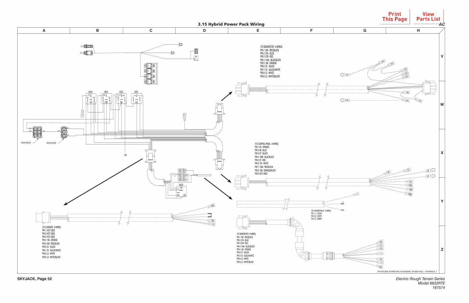
Electric Rough Terrain SeriesModel 6832RTE
167574
SKYJACK, Page 52
A B C D E F G H
V
Z
Y
X
W
3.15 Hybrid Power Pack Wiring
M167653AB, M168037AB, M168038AC, M168041AB_1, M169485/6_1
AC
10
106CR 10CR3
106 104
10CR2
10 57
106A 104A
000
57A10000
106B 57B
85A
86
87
85A104A
000
106CR1
106
19
000
19B
106CR2
106 000
G1
L2
L1
L2
L2
KEYWAY POSITION
85
KEYWAY POSITION
19
(TO GENERATOR - 9 WIRES)PIN 1: 000 - RED/BLACKPIN 2: 57A - BLUEPIN 3: 57B - REDPIN 4: 104A - BLUE/BLACKPIN 5: 106 - ORANGEPIN 6: G1 - BLACKPIN 7: G1 - BLACK/WHITEPIN 8: L2 - WHITEPIN 9: L2 - WHITE/BLACK
000
57A
57B
104A
106
000
104A
000
106
000
57
106A
85
104
106B
86
87
19B
(TO CONTROL PANEL - 8 WIRES)PIN 1: 85 - ORANGEPIN 2: 86 - BLUEPIN 3: 87 - BLACKPIN 4: 106B - BLUE/BLACKPIN 5: 57 - REDPIN 6: 104 - WHITEPIN 7: 106A - RED/BLACKPIN 8: 19B - ORANGE/BLACKPIN 9: NOT USED
57A
57B
106G1
000
L2
(TO GENERATOR - 9 WIRES)PIN 1: 000 - RED/BLACKPIN 2: 57A - BLUEPIN 3: 57B - REDPIN 4: 104A - BLUE/BLACKPIN 5: 106 - ORANGEPIN 6: G1 - BLACKPIN 7: G1 - BLACK/WHITEPIN 8: L2 - WHITEPIN 9: L2 - WHITE/BLACK
104A
000
106G1
L2
(TO CHARGER - 6 WIRES)PIN 1: NOT USEDPIN 2: NOT USEDPIN 3: NOT USEDPIN 4: 106 - ORANGEPIN 5: 000 - RED/BLACKPIN 6: G1 - BLACKPIN 7: G1 - BLACK/WHITEPIN 8: L2 - WHITEPIN 9: L2 - WHITE/BLACK
L1
L2
(TO CHARGER RELAY - 3 WIRES)PIN 1: L1 - BLACKPIN 2: L2 - WHITEPIN 3: G - GREEN
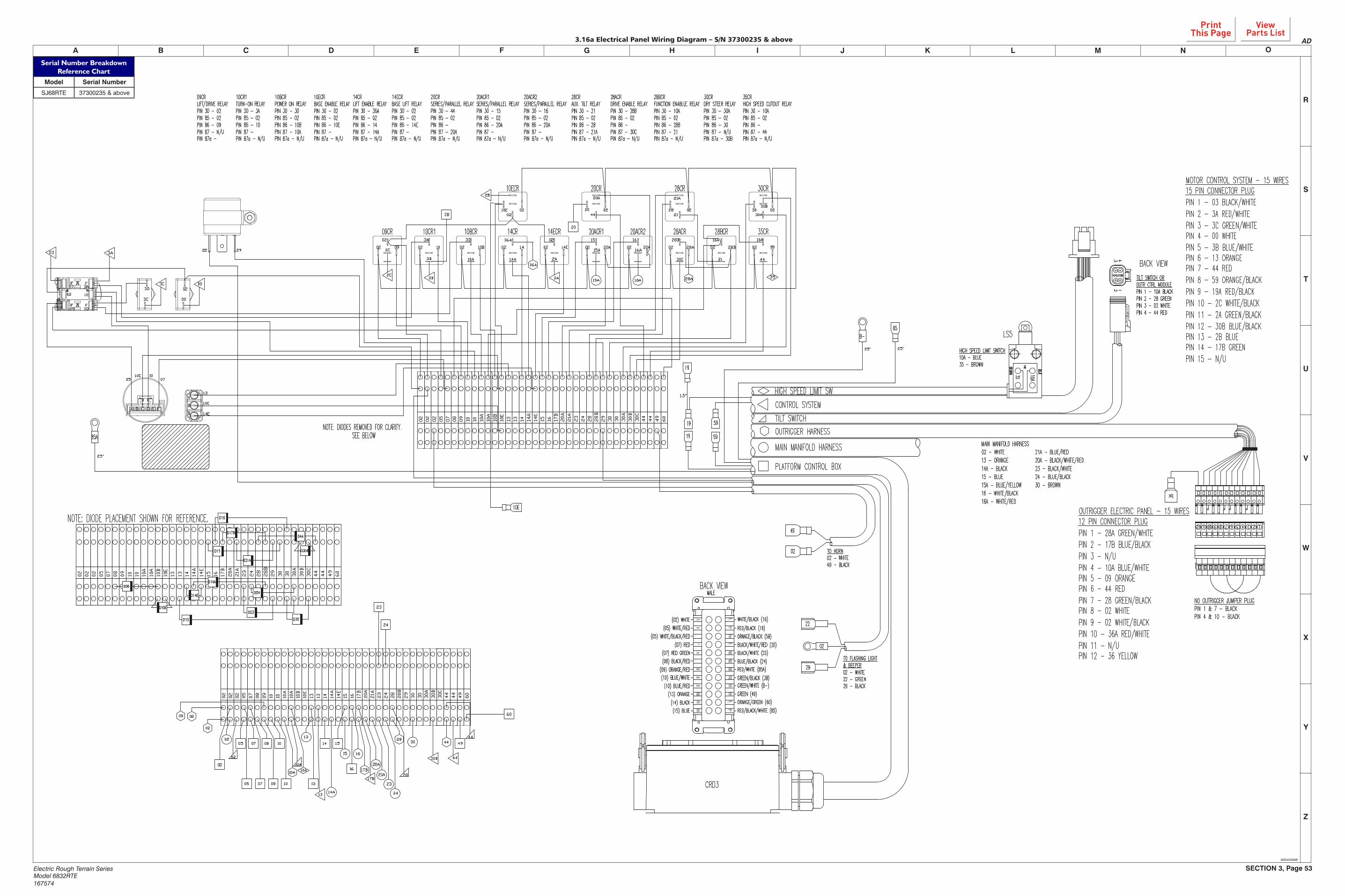
SECTION 3, Page 53Electric Rough Terrain SeriesModel 6832RTE167574
V
W
Y
Z
L M N OF G H K
X
I JEDCBA
U
T
S
R
3.16a Electrical Panel Wiring Diagram – S/N 37300235 & above
M204328AB
fifl flfi
fifi
�flfi
fi�fi�
fi�flfl
flfifl
fifl
�
�
fi��
fifi
AD
Serial Number BreakdownReference Chart
Model Serial Number
SJ68RTE 37300235 & above

SECTION 3, Page 54Electric Rough Terrain SeriesModel 6832RTE167574
V
W
Y
Z
L M N OF G H K
X
I JEDCBA
U
T
S
R
3.16b Electrical Panel Wiring Diagram – S/N 37 300 234 & below
M167300AD
OUTRIGGER ELECTRIC PANEL - 15 WIRES12 PIN CONNECTOR PLUGPIN 1 - 28A GREEN/WHITEPIN 2 - 17B BLUE/BLACK PIN 3 - N/UPIN 4 - 10A BLUE/WHITEPIN 5 - 09 ORANGE PIN 6 - 44 REDPIN 7 - 28 GREEN/BLACKPIN 8 - 02 WHITE PIN 9 - 02 WHITE/BLACKPIN 10 - 36A RED/WHITEPIN 11 - N/UPIN 12 - 36 YELLOW
TILT SWITCHOUTRIGGER HARNESS
PLATFORM CONTROL BOX
HIGH SPEED LIMIT SW
MAIN MANIFOLD HARNESS
CONTROL SYSTEM
TO FLASHING LIGHT& BEEPER02 - WHITE22 - GREEN29 - BLACK
02
29
22
49
02 TO HORN02 - WHITE49 - BLACK
MAIN MANIFOLD HARNESS02 - WHITE 21A - BLUE/RED13 - ORANGE 20A - BLACK/WHITE/RED14A - BLACK 23 - BLACK/WHITE15 - BLUE 24 - BLUE/BLACK15A - BLUE/YELLOW 30 - BROWN16 - WHITE/BLACK16A - WHITE/RED
CRD3
36
1245 37891012 11 6
10A35
HIGH SPEED LIMIT SWITCH10A - BLUE35 - BROWN
LS5
TILT SWITCH OROUTR CTRL MODULEPIN 1 - 10A BLACKPIN 2 - 28 GREENPIN 3 - 02 WHITEPIN 4 - 44 RED
BACK VIEW
59
59
B-
85A
85
NO OUTRIGGER JUMPER PLUGPIN 1 & 7 - BLACKPIN 4 & 10 - BLACK
MOTOR CONTROL SYSTEM - 15 WIRES15 PIN CONNECTOR PLUGPIN 1 - 03 BLACK/WHITEPIN 2 - 3A RED/WHITEPIN 3 - 3C GREEN/WHITEPIN 4 - 00 WHITEPIN 5 - 3B BLUE/WHITEPIN 6 - 13 ORANGEPIN 7 - 44 REDPIN 8 - 59 ORANGE/BLACKPIN 9 - 19A RED/BLACKPIN 10 - 2C WHITE/BLACKPIN 11 - 2A GREEN/BLACKPIN 12 - 30B BLUE/BLACKPIN 13 - 2B BLUEPIN 14 - 17B GREENPIN 15 - N/U
19
19
19
10E
NOBROWN
BLUE
3 4
DEUTSCH
2 1
(02) WHITE WHITE/BLACK (16)
RED/BLACK (19)ORANGE/BLACK (59)
BLACK/WHITE (23)BLUE/BLACK (24)RED/WHITE (85A)GREEN/BLACK (3B)GREEN/WHITE (B-)GREEN (49)ORANGE/GREEN (60)
(07) RED
(13) ORANGE(14) BLACK
(15) BLUE
MALEBACK VIEW
BLACK/WHITE/RED (20)
RED/BLACK/WHITE (85)
(05) WHITE/BLACK/RED(05) WHITE/RED
(07) RED GREEN(08) BLACK/RED
(09) ORANGE/RED(10) BLUE/WHITE
(10) BLUE/RED
02
09CR 10CR1 10BCR 14CR
10ECR
14ECR 20ACR1
20CR
20ACR2 28ACR
28CR
28BCR 35CR
30CR
02 02 02 02 02 02 02 02 02 0209 10 10B 14 14E 20A 20A 28B
02 3A 3D 02 15 16 28B 10A 10A
10A 14A 30C 21 44
02 02 02 0210E 28 3002 44 21 30A
A B C D E F
070510
10E
3A
3D05
02 10
29
10E
13
14E
023D
02 02 05 07 08 09 10 10 10A
10A
10B
10E
13 13 14 14A
14E
15 16 17F
20A
21A
23 24 28 28B
29 30 30 30A
30B
44 44
21A
28A
36A
16A15A35
20
20A
03
2C
3B 2A
3C 00
49
12 2416
1314
1520
1817
1922
2123
12
38
45
76
109
11
22
02 02 02 05 07 08 09 10 10 10A
10A
10B
10E
13 13 14 14A
14E
15 16 17B
20A
21A
23 24 28 28B
29 30 30 30A
30B
44 44
02
05
05 07
07
08
09
10
10 13
14 15
16
23
24
60
49
13
49
4430B
17B
02
02
02
02
09
10A
10A
10A
13
14A
15 16
17B
28
28
30 4444
20A
21A
23
24
2C3B
36A
2B
3B
2A 15A 16A 28A 35
20
003C
3A03
25"
25"35"
30C
30B
30C
PIN 87 - N/UPIN 87a -
PIN 30 - 02LIFT/DRIVE RELAY
PIN 85 - 02PIN 86 - 09
09CR
PIN 87 - PIN 87a - N/U
PIN 30 - 3ATURN-ON RELAY
PIN 85 - 02PIN 86 - 10
10CR1
PIN 87 - 10A
PIN 30 - 3DPOWER ON RELAY
PIN 85 - 02PIN 86 - 10B
10BCR
PIN 87 - PIN 87a - N/U
PIN 30 - 02BASE ENABLE RELAY
PIN 85 - 02PIN 86 - 10E
10ECR
PIN 87 - 14APIN 87a - N/U
PIN 30 - 36ALIFT ENABLE RELAY
PIN 85 - 02PIN 86 - 14
14CR
PIN 87 - PIN 87a - N/U
PIN 30 - 02BASE LIFT RELAY
PIN 85 - 02PIN 86 - 14E
14ECR
PIN 87 - 20APIN 87a - N/U
PIN 30 - 44SERIES/PARALLEL RELAY
PIN 85 - 02PIN 86 -
20CR
PIN 87 - PIN 87a - N/U
PIN 30 - 15SERIES/PARALLEL RELAY
PIN 85 - 02PIN 86 - 20A
20ACR1
PIN 87 - PIN 87a - N/U
PIN 30 - 16SERIES/PARALLEL RELAY
PIN 85 - 02PIN 86 - 20A
20ACR2
PIN 87 - 21APIN 87a - N/U
PIN 30 - 21AUX. TILT RELAY
PIN 85 - 02PIN 86 - 28
28CR
PIN 87 - 30CPIN 87a - N/U
PIN 30 - 28BDRIVE ENABLE RELAY
PIN 85 - 02PIN 86 -
28ACR
PIN 87 - 21PIN 87a - N/U
PIN 30 - 10AFUNCTION ENABLLE RELAY
PIN 85 - 02PIN 86 - 28B
28BCR
PIN 87 - N/UPIN 87a - 30B
PIN 30 - 30ADRY STEER RELAY
PIN 85 - 02PIN 86 - 30
30CR
PIN 87 - 44PIN 87a - N/U
PIN 30 - 10AHIGH SPEED CUTOUT RELAY
PIN 85 - 02PIN 86 -
35CR
PIN 87a - N/U
60
60
1.5"
NOTE: ADD LABEL 169037 ON WIRES 03 AND 3A AT S-STOPADD LABEL 169037 ON TOP OF MAIN DISCONNECT.
02 02 02 05 07 08 09 10 10 10A
10A
10B
10E
13 13 14 14A
14E
15 16 17B
20A
21A
23 24 28 28B
29 30 30 30A
30B
44 44
D08
D10E
D14E
D15
D16
D23
D24
D14A
D13
D44
D21A
4930C
D30B
D30
D17B
NOTE: DIODE PLACEMENT SHOWN FOR REFERENCE.
60
AC
Serial Number BreakdownReference Chart
Model Serial Number
SJ68RTE 37 300 234 & below

SECTION 3, Page 55Electric Rough Terrain SeriesModel 6832RTE167574
V
W
Y
Z
L M N OF G H K
X
I JEDCBA
U
T
S
R
Refer to 3.14 Motor Controller Electrical Schematic.
HIG
H S
PEED
VALV
E SO
LEN
OID
BRA
KEVA
LVE
SOLE
NO
ID
FORW
ARD
VALV
E SO
LEN
OID
PARA
LLEL
FO
RWA
RDVA
LVE
SOLE
NO
ID
SMA
LL P
UM
P D
UM
PVA
LVE
SOLE
NO
ID
REVE
RSE
VALV
E SO
LEN
OID
LEFT
STE
ERIN
GVA
LVE
SOLE
NO
ID
RIG
HT
STEE
RIN
GVA
LVE
SOLE
NO
ID
PARA
LLEL
REV
ERSE
VALV
E SO
LEN
OID
LARG
E PU
MP
DU
MP
VALV
E SO
LEN
OID
SERI
ES/P
ARA
LLEL
RELA
Y
BEEP
ER
LIFT
VA
LVE
SOLE
NO
ID
HO
LDIN
G V
ALV
ESO
LEN
OID
HO
LDIN
G V
ALV
ESO
LEN
OID
MA
IN L
OW
ERIN
GVA
LVE
SOLE
NO
ID
PARA
LLEL
/SER
IES
VALV
E SO
LEN
OID
SERI
ES/P
ARA
LLEL
RELA
Y
SERI
ES/P
ARA
LLEL
RELA
Y
HIG
H S
PEED
CU
TOU
T RE
LAY
38 39 40 41 42 43 44 45 46 47 48 49 50 51 52 53 54 55 56 57 58 59 60 61 62 63 64 65 66 67 68 69 70
FUN
CTI
ON
EN
ABL
ERE
LAY
LIFT
EN
ABL
ERE
LAY
DRY
STE
ERRE
LAY
DRI
VE D
ISA
BLE
RELA
Y
S13
PLAT
FORM
HPP
EN
ABL
E SW
ITCH
07 07 05 05 10 10BL
UE/
RED
WH
ITE/
RED
RED
/GRE
EN
WH
ITE/
BLAC
K/RE
D
BLU
E/W
HIT
E
RED
BLAC
K/RE
D08 20
BLAC
K/W
HIT
E/RE
D
ORA
NG
E/G
REEN
60
LED
-1PO
WER
ON
LIG
HT
RST1
2.7
KOH
MS
6002
0200
BLAC
K
ORA
NG
E
WH
ITE/
BLAC
K
BLU
E
BLU
E/BL
ACK
BLAC
K/W
HIT
E
WH
ITE
CRD
3CR
D2
CRD
1
S3LI
FT/
OFF
/D
RIVE
SWIT
CH
FWD
/UP
REV/
DN
ENA
BLE
0-5V
DC
ORA
NG
E/BL
ACK
5959 A B 8A
RED
/BLA
CK
12B
1914 161513
15 16 1913 14 23 24
23 12B 24
JOYS
TICK
S7
NEU
TRA
LS7
-1
ENA
BLE
S7-6
LEFT
S7-2
RIG
HT
S7-3
08 02
ORA
NG
E/RE
D09
GRE
EN49
080808080808
08
8B
0809
20
49
07 0510 10
D12
B
GRE
EN/B
LACK
GRE
EN/W
HIT
E
V
BATT
ERY
VOLT
MET
ER
RED
/WH
ITE
RED
/BLA
CK/W
HIT
E
3B
8585
85A
85A
C1
S8H
ORN
TORQ
UE
SWIT
CHS1
6
07 07 05 05 10 10 08H
1
4902
B148
V
02
003C3B03592C2B132A4430B
0810
B
00
3C3D
3D10
A
3D05 3A
03
3D
INVE
RTER
OPT
ION
POW
ER O
NRE
LAY
HO
RN
GRO
UN
D C
IRCU
ITBR
EAKE
R
LIFT
/DRI
VERE
LAY
48 V
OLT
BATT
ERY
BASE
/PLA
TFO
RMRE
LAY
10E
13
14E
D10
E
1002
13
14E
10E
D08
10
10
3A
03
05
10B
0210
BCR
0902
02
09CR
2C
02
02
02
2B
10EC
R
14E
02
14EC
R
2A
02 02
02
12V
CIRC
UIT
BREA
KER
BASE
LIF
TRE
LAY
17B
09
10E
10
10CR
2
A3
A5
S12
HPP
ON
/OFF
SW
ITCH
A2
S11
HPP
MA
N./A
UTO
SW
ITCH
A1
10CR
1
3B
0210CR
3
A6
106C
R
A7
A4
HPP BATT. GND
HPP 12V
HPP OFF
HPP BATT.
HPP ENGINE START
B14
B11
B7B12
B6 B13
B10
B8 B9 B1 B3
3A
3A
3AB2 B5 B4
CAN
M.D
.I
3A3B
PANEL CONNECTOR BPANEL CONNECTOR A
PAN
EL C
ON
NEC
TOR
C
106C
R2
CHA
RGER
L1L2
1919
PAN
EL C
ON
NEC
TOR
D
1
2
3
4
5
6
MO
TOR
ENCO
DER
HPP-
HPP+
57A
104A
000
106
57B
106A
106B
106A
106B
57
5757B
57A
3B
3B
85A
85
8585
A
8586 87
104
104
10
106
000
85B
106
000
86 A
UTO
87 M
AN
.
UP/
DO
WN
SWIT
CH
S2
(IN ID
LE P
OSI
TIO
N)
IDLE
/PLT
F/BA
SEKE
Y SW
ITCH
S10
S6EM
ERG
ENCY
STO
P
L2
104A
000
104A
000
S1M
AIN
PO
WER
DIS
CON
NEC
T
GEN
. STA
RTRE
LAY
TURN
-ON
RELA
Y
GEN
. OFF
RELA
Y
GEN
. RU
NN
ING
RELA
Y
LIG
HT
LED
-2PO
WER
ON
3A
1 2 3 4 5 6 7 8 9 10 11 12 13 14 15 16 17 18 19 20 21 22 23 24 25 26 27 28 29 30 31 32 33 34 35 36 37
HYB
RID
PO
WER
PACK
CO
NN
ECTO
R
85A
6049
2H-2
0B
D02
-8
D02
-7
D02
-13
D02
-12
D02
-11
2H-2
1A-1
4H-1
6A
4H-1
6
3H-3
0D
02-1
0
D02
-9
D02
-15
D02
-144H
-15
4H-1
5A
4H-2
3
4H-2
4
D02
-6
D02
-1 2H-2
1A
4H-2
0A
D02
-5
BP-2
929
3H-1
4AD
02-4
D02
-3
D02
-2 2H-1
3-1
2H-1
3-2
2H-1
3
3510
A35
35CR
10A
10A
44
D44
4420
A
D14
E
15A
15
16A
16
20 13 14 15 16 23 24 0259 1909
10A
10A
02
44
2002
20CR
20A
20A
02
02
20AC
R1
20AC
R2
59
13
14A
28B
28B
02
28BC
R
2121
A
2828
02
28CR
21A
D21
A
D14
A
D30
D30
B
D15
D16
D16
AD
15A
D23
D24
30A
30B
30CR
3002
20B
1615
23
24
30B
13 14A
D13
LS5
TILT
OVE
RRID
E/H
IGH
DRI
VE C
UTO
UT
LIM
IT S
WIT
CHN
ORM
ALL
Y CL
OSE
D
59
10E
10B
1402
14CR
14
36A
14A
28AC
R
28A
02
17B
02
FUN
CTI
ON
EN
ABL
ERE
LAY
S4
STO
PEM
ERG
ENCY
106
000
104A
57B
57A
10
L2
G1 G1
L1 G1
L2
L1A
L1A
L1A
17B
28B
D17
B
48+
48+
48+
48+
48-
48-
48-
48+
48+
48-
48-
8B
CB2
CB1
19
106C
R1 106
000
1919
19B
19B
19B
000
A8
JUM
PER
2N
O O
UTR
IGG
ER
JUM
PER
1N
O O
UTR
IGG
ER
10A
36A
2828
A
28
02
TS1
TILT
SWIT
CH
10A
28
10E
0507
10
M169308AB-1
3.17a Electrical Schematic – No Options – S/N 37300235 & above
Serial Number BreakdownReference Chart
Model Serial Number
SJ68RTE 37300235 & above

SECTION 3, Page 56Electric Rough Terrain SeriesModel 6832RTE167574
V
W
Y
Z
L M N OF G H K
X
I JEDCBA
U
T
S
R
Refer to 3.14 Motor Controller Electrical Schematic.
HIG
H S
PE
ED
VALV
E S
OLE
NO
ID
BR
AK
EVA
LVE
SO
LEN
OID
FOR
WA
RD
VALV
E S
OLE
NO
ID
PAR
ALL
EL
FOR
WA
RD
VALV
E S
OLE
NO
ID
SM
ALL
PU
MP
DU
MP
VALV
E S
OLE
NO
ID
RE
VE
RS
EVA
LVE
SO
LEN
OID
LEF
T S
TEE
RIN
GVA
LVE
SO
LEN
OID
RIG
HT
STE
ER
ING
VALV
E S
OLE
NO
ID
PAR
ALL
EL
RE
VE
RS
EVA
LVE
SO
LEN
OID
LAR
GE
PU
MP
DU
MP
VA
LVE
SO
LEN
OID
SE
RIE
S/P
AR
ALL
EL
RE
LAY
BE
EP
ER
LIF
T VA
LVE
SO
LEN
OID
HO
LDIN
G V
ALV
ES
OLE
NO
ID
HO
LDIN
G V
ALV
ES
OLE
NO
ID
MA
IN L
OW
ER
ING
VALV
E S
OLE
NO
ID
PAR
ALL
EL/
SE
RIE
S
VALV
E S
OLE
NO
ID
SE
RIE
S/P
AR
ALL
EL
RE
LAY
SE
RIE
S/P
AR
ALL
EL
RE
LAY
HIG
H S
PE
ED
C
UTO
UT
RE
LAY
38 39 40 41 42 43 44 45 46 47 48 49 50 51 52 53 54 55 56 57 58 59 60 61 62 63 64 65 66 67 68 69 70
FUN
CTI
ON
EN
AB
LER
ELA
Y
LIF
T E
NA
BLE
RE
LAY
DR
Y S
TEE
RR
ELA
Y
DR
IVE
DIS
AB
LER
ELA
Y
S13
PLA
TFO
RM
HP
P
EN
AB
LE S
WIT
CH
07 07 05 05 10 10B
LUE
/RE
D
WH
ITE
/RE
D
RE
D/G
RE
EN
WH
ITE
/BLA
CK
/RE
D
BLU
E/W
HIT
E
RE
D
BLA
CK
/RE
D08 20
BLA
CK
/WH
ITE
/RE
D
OR
AN
GE
/GR
EE
N60
LED
-1P
OW
ER
ON
LIG
HT
RS
T12.
7 K
OH
MS
6002
0200
BLA
CK
OR
AN
GE
WH
ITE
/BLA
CK
BLU
E
BLU
E/B
LAC
K
BLA
CK
/WH
ITE
WH
ITE
CR
D3
CR
D2
CR
D1
S3
LIF
T/O
FF/
DR
IVE
SW
ITC
H
FWD
/UP
RE
V/D
N
EN
AB
LE
0-5V
DC
OR
AN
GE
/BLA
CK
5959 A B 8A
RE
D/B
LAC
K
12B
1914 161513
15 16 1913 14 23 24
23 12B 24
JOY
STI
CK
S
7
NE
UTR
AL
S7-
1
EN
AB
LES
7-6
LEF
TS
7-2
RIG
HT
S7-
3
08 02
OR
AN
GE
/RE
D09
GR
EE
N49
080808080808
08
8B
0809
20
49
07 0510 10
D12
B
GR
EE
N/B
LAC
K
GR
EE
N/W
HIT
E
V
BA
TTE
RY
VO
LTM
ETE
R
RE
D/W
HIT
E
RE
D/B
LAC
K/W
HIT
E
3B
8585
85A
85A
C1
S8
HO
RN
TOR
QU
E S
WIT
CH
S16
07 07 05 05 10 10 08H
1
4902
B1
48V
02
003C3B03592C2B132A4430B
0810
B
00
3C3D
3D10
A
3D05
05
3A03
3D
INV
ER
TER
OP
TIO
N
PO
WE
R O
NR
ELA
Y
HO
RN
GR
OU
ND
CIR
CU
ITB
RE
AK
ER
LIF
T/D
RIV
ER
ELA
Y
48 V
OLT
BA
TTE
RY
BA
SE
/PLA
TFO
RM
RE
LAY
10
07 10E
10E
13
14E
D10
E
1002
13
14E
10E
D08
10
10
3A
03
05
10B
0210
BC
R
0902
02
09C
R
2C
02
02
02
2B
10E
CR
14E
02
14E
CR
2A
02 02
02
12V
CIR
CU
ITB
RE
AK
ER
BA
SE
LIF
TR
ELA
Y
17B
09
10E
10
10C
R2
A3
A5
S12
HP
P O
N/O
FF
SW
ITC
H
A2
S11
HP
P M
AN
./AU
TO
SW
ITC
H
A1
10C
R1
3B
0210C
R3
A6
106C
R
A7
A4
HPP BATT. GND
HPP 12V
HPP OFF
HPP BATT.
HPP ENGINE START
B14 B11
B7
B12 B6
B13 B10 B8
B9 B1
B3
3A
3A
3AB
2 B5
B4
CA
NM
.D.I
3A3B
PANEL CONNECTOR BPANEL CONNECTOR A
PAN
EL
CO
NN
EC
TOR
C
106C
R2
CH
AR
GE
RL1L2
1919
PAN
EL
CO
NN
EC
TOR
D
1
2
3
4
5
6
MO
TOR
EN
CO
DE
R
HPP-
HPP+
57A
104A
000
106
57B
106A
106B
106A
106B
57
5757B
57A
3B
3B
85A
85
8585
A
8586 87
104
104
10
106
000
85B
106
000
86 A
UTO
87 M
AN
.
UP
/DO
WN
SW
ITC
H
S2
(IN ID
LE P
OS
ITIO
N)
PLT
F/ID
LE/B
AS
EK
EY
SW
ITC
H
S10
S6
EM
ER
GE
NC
YS
TOP
L2
104A
000
104A
000
S1
MA
IN P
OW
ER
DIS
CO
NN
EC
T
GE
N. S
TAR
TR
ELA
Y
TUR
N-O
NR
ELA
Y
GE
N. O
FFR
ELA
Y
GE
N. R
UN
NIN
GR
ELA
Y
LIG
HT
LED
-2P
OW
ER
ON
3A
1 2 3 4 5 6 7 8 9 10 11 12 13 14 15 16 17 18 19 20 21 22 23 24 25 26 27 28 29 30 31 32 33 34 35 36 37
HY
BR
ID P
OW
ER
PAC
K C
ON
NE
CTO
R
85A
6049
2H-2
0B
D02
-8
D02
-7
D02
-13
D02
-12
D02
-11
2H-2
1A-1
4H-1
6A
4H-1
6
3H-3
0D
02-1
0
D02
-9
D02
-15
D02
-144H
-15
4H-1
5A
4H-2
3
4H-2
4
D02
-6
D02
-1 2H-2
1A
4H-2
0A
D02
-5
BP-
2929
3H-1
4AD
02-4
D02
-3
D02
-2 2H-1
3-1
2H-1
3-2
2H-1
3
3510
A35
35C
R
10A
10A
44
D44
4420
A
D14
E
15A
15
16A
16
20 13 14 15 16 23 24 0259 1909
10A
10A
02
44
2002
20C
R
20A
20A
02
02
20A
CR
1
20A
CR
2
59
13
14A
28B
28B
02
28B
CR
2121
A
2828
02
28C
R
21A
D21
A
D14
A
D30
D30
B
D15
D16
D16
AD
15A
D23
D24
30A
30B
30C
R
3002
20B
1615
23
24
30B
13 14A
D13
LS5
TILT
OV
ER
RID
E/
HIG
H D
RIV
E C
UTO
UT
LIM
IT S
WIT
CH
NO
RM
ALL
Y C
LOS
ED
59
10E
10B
1402
14C
R
14
36A
14A
28A
CR
28A
02
17B
02
FUN
CTI
ON
EN
AB
LER
ELA
Y
S4
STO
PE
ME
RG
EN
CY
106
000
104A
57B
57A
10
L2
G1 G1
L1 G1
L2
L1A
L1A
L1A
17B
28B
D17
B
48+
48+
48+
48+
48-
48-
48-
48+
48+
48-
48-
8B
CB
2
CB
1
19
106C
R1 10
600
0
1919
19B
19B
19B
000
A8
JUM
PE
R 2
NO
OU
TRIG
GE
R
JUM
PE
R 1
NO
OU
TRIG
GE
R
10A
36A
2828
A
28
02
TS1
TILT
SW
ITC
H
10A
28
M169308AB-1
3.17b Electrical Schematic – No Options – S/N 37300234 & below
Serial Number BreakdownReference Chart
Model Serial Number
SJ68RTE 37300234 & below

SECTION 3, Page 57Electric Rough Terrain SeriesModel 6832RTE167574
V
W
Y
Z
L M N OF G H K
X
I JEDCBA
U
T
S
R
Refer to 3.14 Motor Controller Electrical Schematic.
HIG
H S
PEED
VALV
E SO
LEN
OID
BRA
KEVA
LVE
SOLE
NO
ID
FORW
ARD
VALV
E SO
LEN
OID
PARA
LLEL
FO
RWA
RDVA
LVE
SOLE
NO
ID
SMA
LL P
UM
P D
UM
PVA
LVE
SOLE
NO
ID
REVE
RSE
VALV
E SO
LEN
OID
LEFT
STE
ERIN
GVA
LVE
SOLE
NO
ID
RIG
HT
STEE
RIN
GVA
LVE
SOLE
NO
ID
PARA
LLEL
REV
ERSE
VALV
E SO
LEN
OID
LARG
E PU
MP
DU
MP
VALV
E SO
LEN
OID
SERI
ES/P
ARA
LLEL
RELA
Y
BEEP
ER
LIFT
VA
LVE
SOLE
NO
ID
HO
LDIN
G V
ALV
ESO
LEN
OID
HO
LDIN
G V
ALV
ESO
LEN
OID
MA
IN L
OW
ERIN
GVA
LVE
SOLE
NO
ID
PARA
LLEL
/SER
IES
VALV
E SO
LEN
OID
SERI
ES/P
ARA
LLEL
RELA
Y
SERI
ES/P
ARA
LLEL
RELA
Y
HIG
H S
PEED
CU
TOU
T RE
LAY
UP
RELA
Y
LEFT
REA
R U
PO
UTR
IGG
ER S
OLE
NO
ID
LEFT
REA
R D
OW
NO
UTR
IGG
ER S
OLE
NO
ID
RIG
HT
REA
R D
OW
NO
UTR
IGG
ER S
OLE
NO
ID
RIG
HT
REA
R U
PO
UTR
IGG
ER S
OLE
NO
ID
RIG
HT
FRO
NT
DO
WN
OU
TRIG
GER
SO
LEN
OID
RIG
HT
FRO
NT
UP
OU
TRIG
GER
SO
LEN
OID
LEFT
FRO
NT
DO
WN
OU
TRIG
GER
SO
LEN
OID
LEFT
FRO
NT
UP
OU
TRIG
GER
SO
LEN
OID
GRO
UN
D
AUTO
LEV
EL
AUTO
RET
RAC
T
OU
TRIG
GER
LIG
HT
POW
ER
OU
TRIG
GER
EN
ABL
E
RIG
HT
FRO
NT
DO
WN
RIG
HT
REA
R D
OW
N
LEFT
FRO
NT
DO
WN
LIFT
EN
ABL
E
LEFT
REA
R D
OW
N
TILT
LEFT
REA
R D
OW
N
TILT
OVE
RRID
E/H
IGH
DRI
VE C
UTO
UT
RIG
HT
REA
R U
P
LEFT
REA
R U
P
LEFT
FRO
NT
DO
WN
RIG
HT
FRO
NT
DO
WN
RIG
HT
REA
R D
OW
N
LEFT
FRO
NT
UP
RIG
HT
FRO
NT
UP
OU
TRIG
GER
CON
TRO
L M
OD
ULE
OU
TRIG
GER
LIFT
DIS
ABL
E RE
LAY
OU
TRIG
GER
PRO
OF
RELA
Y
OU
TRIG
GER
HO
LDIN
G S
OLE
NO
ID
OU
TRIG
GER
DRI
VEEN
ABL
E RE
LAY
OU
TRIG
GER
LIF
TEN
ABL
E RE
LAY
OU
TRIG
GER
ENA
BLE
RELA
Y
38 39 40 41 42 43 44 45 46 47 48 49 50 51 52 53 54 55 56 57 58 59 60 61 62 63 64 65 66 67 68 69 70 71 72 73 74 75 76 77 78 79 80 81 82 83 84 85 86 87 88 89 90 91 92 93 94 95 96 97 98 99 100
101
102
103
104
105
106
107
108
109
110
111
FUN
CTI
ON
EN
ABL
ERE
LAY
LIFT
EN
ABL
ERE
LAY
DRY
STE
ERRE
LAY
DRI
VE D
ISA
BLE
RELA
Y
S13
PLAT
FORM
HPP
EN
ABL
E SW
ITCH
07 07 05 05 10 10BL
UE/
RED
WH
ITE/
RED
RED
/GRE
EN
WH
ITE/
BLAC
K/RE
D
BLU
E/W
HIT
E
RED
BLAC
K/RE
D08 20
BLAC
K/W
HIT
E/RE
D
ORA
NG
E/G
REEN
60
LED
-1PO
WER
ON
LIG
HT
RST1
2.7
KOH
MS
6002
0200
BLAC
K
ORA
NG
E
WH
ITE/
BLAC
K
BLU
E
BLU
E/BL
ACK
BLAC
K/W
HIT
E
WH
ITE
CRD
3CR
D2
CRD
1
S3LI
FT/
OFF
/D
RIVE
SWIT
CH
FWD
/UP
REV/
DN
ENA
BLE
0-5V
DC
ORA
NG
E/BL
ACK
5959 A B 8A
RED
/BLA
CK
12B
1914 161513
15 16 1913 14 23 24
23 12B 24
JOYS
TICK
S7
NEU
TRA
LS7
-1
ENA
BLE
S7-6
LEFT
S7-2
RIG
HT
S7-3
08 02
ORA
NG
E/RE
D09
GRE
EN49
080808080808
08
8B
0809
20
49
07 0510 10
D12
B
GRE
EN/B
LACK
GRE
EN/W
HIT
E
V
BATT
ERY
VOLT
MET
ER
RED
/WH
ITE
RED
/BLA
CK/W
HIT
E
3B
8585
85A
85A
C1
S8H
ORN
TORQ
UE
SWIT
CHS1
6
07 07 05 05 10 10 08H
1
4902
B148
V
02
003C3B03592C2B132A4430B
0810
B
00
3C3D
3D10
A
3D05 3A
03
3D
INVE
RTER
OPT
ION
POW
ER O
NRE
LAY
HO
RN
GRO
UN
D C
IRCU
ITBR
EAKE
R
LIFT
/DRI
VERE
LAY
48 V
OLT
BATT
ERY
BASE
/PLA
TFO
RMRE
LAY
10E
13
14E
D10
E
1002
13
14E
10E
D08
10
10
3A
03
05
10B
0210
BCR
0902
02
09CR
2C
02
02
02
2B
10EC
R
14E
02
14EC
R
2A
02 02
02
12V
CIRC
UIT
BREA
KER
BASE
LIF
TRE
LAY
17B
09
10E
10
10CR
2
A3
A5
S12
HPP
ON
/OFF
SW
ITCH
A2
S11
HPP
MA
N./A
UTO
SW
ITCH
A1
10CR
1
3B
0210CR
3
A6
106C
R
A7
A4
HPP BATT. GND
HPP 12V
HPP OFF
HPP BATT.
HPP ENGINE START
B14
B11
B7B12
B6 B13
B10
B8 B9 B1 B3
3A
3A
3AB2 B5 B4
CAN
M.D
.I
3A3B
PANEL CONNECTOR BPANEL CONNECTOR A
PAN
EL C
ON
NEC
TOR
C
106C
R2
CHA
RGER
L1L2
1919
PAN
EL C
ON
NEC
TOR
D
1
2
3
4
5
6
MO
TOR
ENCO
DER
HPP-
HPP+
57A
104A
000
106
57B
106A
106B
106A
106B
57
5757B
57A
3B
3B
85A
85
8585
A
8586 87
104
104
10
106
000
85B
106
000
86 87
UP/
DO
WN
SWIT
CH
S2
S6EM
ERG
ENCY
STO
P
L2
104A
000
104A
000
S1M
AIN
PO
WER
DIS
CON
NEC
T
GEN
. STA
RTRE
LAY
TURN
-ON
RELA
Y
GEN
. OFF
RELA
Y
GEN
. RU
NN
ING
RELA
Y
LIG
HT
LED
-2PO
WER
ON
3A
1 2 3 4 5 6 7 8 9 10 11 12 13 14 15 16 17 18 19 20 21 22 23 24 25 26 27 28 29 30 31 32 33 34 35 36 37
85A
6049
2H-2
0B
D02
-8
D02
-7
D02
-13
D02
-12
D02
-11
2H-2
1A-1
4H-1
6A
4H-1
6
3H-3
0D
02-1
0
D02
-9
D02
-15
D02
-144H
-15
4H-1
5A
4H-2
3
4H-2
4
D02
-6
D02
-1 2H-2
1A
4H-2
0A
D02
-5
BP-2
929
3H-1
4AD
02-4
D02
-3
D02
-2 2H-1
3-1
2H-1
3-2
2H-1
3
3510
A35
35CR
10A
10A
44
D44
4420
A
D14
E
15A
15
16A
16
20 13 14 15 16 23 24 0259 1909
10A
10A
02
44
2002
20CR
20A
20A
02
02
20AC
R1
20AC
R2
59
13
14A
28B
28B
02
28BC
R
2121
A
2828
02
28CR
21A
D21
A
D14
A
D30
D30
B
D15
D16
D16
AD
15A
D23
D24
30A
30B
30CR
3002
20B
1615
23
24
30B
13 14A
D13
LS5
TILT
OVE
RRID
E/H
IGH
DRI
VE C
UTO
UT
LIM
IT S
WIT
CHN
ORM
ALL
Y CL
OSE
D
59
10E
10B
1402
14CR
14
36A
14A
GG 28
A
28HH
2828
A
35C
35C
35C
35C
KK36A
CUT
J17D
10A
J17E
17E
10A
10A
4H-7
4
4H-7
8
4H-7
7
4H-7
2
4H-7
5
4H-7
6
4H-7
1
4H-7
3
70 =
P2-
5
70A
= P
2-7
79 =
P2-
6
02 =
P2-
11
78
74
77
73
76
72
71
75
35C
= P4
-9
66A
= P
2-3
67A
= P
2-2
10A
= P
2-12
65A
= P
2-4
78 =
P4-
1
44 =
P2-
10
28 =
P2-
9
65 =
P2-
8
68A
= P
2-1
73 =
P4-
6
74 =
P4-
5
75 =
P4-
4
76 =
P4-
3
77 =
P4-
2
71 =
P4-
8
OCM
1
72 =
P4-
7
2H-1
7C
II,JJ
BB
LS65
67A
65A
LS67
10A
10A
LS66
66A
RIG
HT
FRO
NT
10A
LS68
68A
10A
LEFT
REA
R
NO
RMA
LLY
CLO
SED
HEL
D O
PEN
OU
TRIG
GER
DO
WN
LIM
IT S
WIT
CHES
RIG
HT
REA
R
LEFT
FRO
NT
RETR
ACTE
D P
OSI
TIO
NO
UTR
IGG
ERS
SHO
WN
IN
D71
D72
D74
D75
D77
D78
D76
17D
CR
17D
D73
74
77
DN
UP
DN
UP
S22A
S23A
REA
R LE
FT
73
76
75
72
DN
UP
S21A
71D
N
UP
S20A
FRO
NT
RIG
HT
REA
R RI
GH
T
78
17C
D17
C-2
PP
65CR
65
10A
D36
61D
36-1
CUT
J36
MM
NN
36
LEFT
FRO
NT
LS61
RIG
HT
FRO
NT
62LS
6263
61CR
D17
C-1
7877 74
BLU
E/BL
ACK
BLAC
K
BLAC
K/W
HIT
E
77 74 78
UP
DN
S23
35D
DN
73767271 75
RED
/BLA
CK
BLU
E
RED
ORA
NG
E
ORA
NG
E/BL
ACK
0270A
79 70
WH
ITE
GRE
EN/B
LACK
GRE
EN
RED
/WH
ITE
76 7371 75 72
UP
S22
UP
DN
35D
35D
S21
DN
UP
35D
027079 70A
OL1
OU
TRIG
GER
LIG
HT
0235D
LEVE
L
ALL
UP
S20
FRO
NT
LEFT
FRO
NT
RIG
HT
REA
RRI
GH
T
REA
RLE
FT
MO
DE
AUTO
10A
10A
35C
65
35E
S9B
35C O
UTR
IGG
EREN
ABL
E
35C
35B
44
35C
WH
ITE/
BLAC
K
BLU
E/W
HIT
E
GRE
EN/W
HIT
E
44
35C
S9A
ENA
BLE
OU
TRIG
GER
35C
6410
ALS
64
LEFT
REA
R
09
9CR2
9CR3
CCFF
EE
09
35D
WIT
H A
UTO
LEV
ELLI
NG
OU
TRIG
GER
OPT
ION
S24
OU
TRIG
GER
UP
LIM
IT S
WIT
CHES
N
ORM
ALL
Y O
PEN
HEL
D C
LOSE
D
OU
TRIG
GER
S SH
OW
N IN
RE
TRAC
TED
PO
SITI
ON
LS63
RIG
HT
REA
R
FRO
NT
LEFT
D02
-25
D02
-24
D02
-23
D02
-22
D02
-21
D02
-20
D02
-19
D02
-18
D02
-17
2817
B36
A
44
4409
28AC
R
28A
02
28A
36A
17B 17
B
02
FUN
CTI
ON
EN
ABL
ERE
LAY
S4
STO
PEM
ERG
ENCY
28A
112
113
114
106
000
104A
57B
57A
10
L2
G1 G1
L1 G1
L2
L1A
L1A
L1A
17B
28B
D17
B
48+
48+
48+
48+
48-
48-
48-
48+
48+
48-
48-
8B
28 28
CB2
CB1
19
106C
R1 106
000
1919
19B
19B
19B
000
A8
HYB
RID
PO
WER
PACK
CO
NN
ECTO
R
100
0237
KEY
D07
D10
E-2
10E
07
10ED
10E-
1
19D
19
100
(48V
)
0202
100
(12V
)
100
100
100
10E10
E
10E
07
07
19
TELE
MAT
ICS
KEY
SWIT
CH(IN
IDLE
PO
SITI
ON
)
IDLE
/PLT
F/BA
SES1
0
10E
0507
10
TELE
MAT
ICS
OP
TIO
N
DC
-DC
M167372AD-1
3.18a Electrical Schematic – All Options – S/N 37300235 & above AD
Serial Number BreakdownReference Chart
Model Serial Number
SJ68RTE 37300235 & above
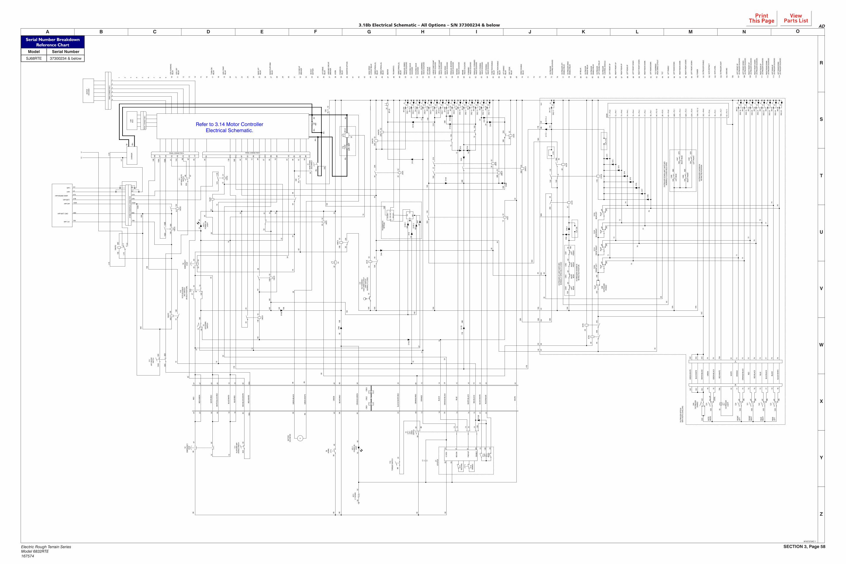
SECTION 3, Page 58Electric Rough Terrain SeriesModel 6832RTE167574
V
W
Y
Z
L M N OF G H K
X
I JEDCBA
U
T
S
R
Refer to 3.14 Motor Controller Electrical Schematic.
HIG
H S
PEED
VALV
E SO
LEN
OID
BRA
KEVA
LVE
SOLE
NO
ID
FORW
ARD
VALV
E SO
LEN
OID
PARA
LLEL
FO
RWA
RDVA
LVE
SOLE
NO
ID
SMA
LL P
UM
P D
UM
PVA
LVE
SOLE
NO
ID
REVE
RSE
VALV
E SO
LEN
OID
LEFT
STE
ERIN
GVA
LVE
SOLE
NO
ID
RIG
HT
STEE
RIN
GVA
LVE
SOLE
NO
ID
PARA
LLEL
REV
ERSE
VALV
E SO
LEN
OID
LARG
E PU
MP
DU
MP
VALV
E SO
LEN
OID
SERI
ES/P
ARA
LLEL
RELA
Y
BEEP
ER
LIFT
VA
LVE
SOLE
NO
ID
HO
LDIN
G V
ALV
ESO
LEN
OID
HO
LDIN
G V
ALV
ESO
LEN
OID
MA
IN L
OW
ERIN
GVA
LVE
SOLE
NO
ID
PARA
LLEL
/SER
IES
VALV
E SO
LEN
OID
SERI
ES/P
ARA
LLEL
RELA
Y
SERI
ES/P
ARA
LLEL
RELA
Y
HIG
H S
PEED
CU
TOU
T RE
LAY
UP
RELA
Y
LEFT
REA
R U
PO
UTR
IGG
ER S
OLE
NO
ID
LEFT
REA
R D
OW
NO
UTR
IGG
ER S
OLE
NO
ID
RIG
HT
REA
R D
OW
NO
UTR
IGG
ER S
OLE
NO
ID
RIG
HT
REA
R U
PO
UTR
IGG
ER S
OLE
NO
ID
RIG
HT
FRO
NT
DO
WN
OU
TRIG
GER
SO
LEN
OID
RIG
HT
FRO
NT
UP
OU
TRIG
GER
SO
LEN
OID
LEFT
FRO
NT
DO
WN
OU
TRIG
GER
SO
LEN
OID
LEFT
FRO
NT
UP
OU
TRIG
GER
SO
LEN
OID
GRO
UN
D
AUTO
LEV
EL
AUTO
RET
RAC
T
OU
TRIG
GER
LIG
HT
POW
ER
OU
TRIG
GER
EN
ABL
E
RIG
HT
FRO
NT
DO
WN
RIG
HT
REA
R D
OW
N
LEFT
FRO
NT
DO
WN
LIFT
EN
ABL
E
LEFT
REA
R D
OW
N
TILT
LEFT
REA
R D
OW
N
TILT
OVE
RRID
E/H
IGH
DRI
VE C
UTO
UT
RIG
HT
REA
R U
P
LEFT
REA
R U
P
LEFT
FRO
NT
DO
WN
RIG
HT
FRO
NT
DO
WN
RIG
HT
REA
R D
OW
N
LEFT
FRO
NT
UP
RIG
HT
FRO
NT
UP
OU
TRIG
GER
CON
TRO
L M
OD
ULE
OU
TRIG
GER
LIFT
DIS
ABL
E RE
LAY
OU
TRIG
GER
PRO
OF
RELA
Y
OU
TRIG
GER
HO
LDIN
G S
OLE
NO
ID
OU
TRIG
GER
DRI
VEEN
ABL
E RE
LAY
OU
TRIG
GER
LIF
TEN
ABL
E RE
LAY
OU
TRIG
GER
ENA
BLE
RELA
Y
38 39 40 41 42 43 44 45 46 47 48 49 50 51 52 53 54 55 56 57 58 59 60 61 62 63 64 65 66 67 68 69 70 71 72 73 74 75 76 77 78 79 80 81 82 83 84 85 86 87 88 89 90 91 92 93 94 95 96 97 98 99 100
101
102
103
104
105
106
107
108
109
110
111
FUN
CTI
ON
EN
ABL
ERE
LAY
LIFT
EN
ABL
ERE
LAY
DRY
STE
ERRE
LAY
DRI
VE D
ISA
BLE
RELA
Y
S13
PLAT
FORM
HPP
EN
ABL
E SW
ITCH
07 07 05 05 10 10BL
UE/
RED
WH
ITE/
RED
RED
/GRE
EN
WH
ITE/
BLAC
K/RE
D
BLU
E/W
HIT
E
RED
BLAC
K/RE
D08 20
BLAC
K/W
HIT
E/RE
D
ORA
NG
E/G
REEN
60
LED
-1PO
WER
ON
LIG
HT
RST1
2.7
KOH
MS
6002
0200
BLAC
K
ORA
NG
E
WH
ITE/
BLAC
K
BLU
E
BLU
E/BL
ACK
BLAC
K/W
HIT
E
WH
ITE
CRD
3CR
D2
CRD
1
S3LI
FT/
OFF
/D
RIVE
SWIT
CH
FWD
/UP
REV/
DN
ENA
BLE
0-5V
DC
ORA
NG
E/BL
ACK
5959 A B 8A
RED
/BLA
CK
12B
1914 161513
15 16 1913 14 23 24
23 12B 24
JOYS
TICK
S7
NEU
TRA
LS7
-1
ENA
BLE
S7-6
LEFT
S7-2
RIG
HT
S7-3
08 02
ORA
NG
E/RE
D09
GRE
EN49
080808080808
08
8B
0809
20
49
07 0510 10
D12
B
GRE
EN/B
LACK
GRE
EN/W
HIT
E
V
BATT
ERY
VOLT
MET
ER
RED
/WH
ITE
RED
/BLA
CK/W
HIT
E
3B
8585
85A
85A
C1
S8H
ORN
TORQ
UE
SWIT
CHS1
6
07 07 05 05 10 10 08H
1
4902
B148
V
02
003C3B03592C2B132A4430B
0810
B
00
3C3D
3D10
A
3D05
05
3A03
3D
INVE
RTER
OPT
ION
POW
ER O
NRE
LAY
HO
RN
GRO
UN
D C
IRCU
ITBR
EAKE
R
LIFT
/DRI
VERE
LAY
48 V
OLT
BATT
ERY
BASE
/PLA
TFO
RMRE
LAY
10
07 10E
10E
13
14E
D10
E
1002
13
14E
10E
D08
10
10
3A
03
05
10B
0210
BCR
0902
02
09CR
2C
02
02
02
2B
10EC
R
14E
02
14EC
R
2A
02 02
02
12V
CIRC
UIT
BREA
KER
BASE
LIF
TRE
LAY
17B
09
10E
10
10CR
2
A3
A5
S12
HPP
ON
/OFF
SW
ITCH
A2
S11
HPP
MA
N./A
UTO
SW
ITCH
A1
10CR
1
3B
0210CR
3
A6
106C
R
A7
A4
HPP BATT. GND
HPP 12V
HPP OFF
HPP BATT.
HPP ENGINE START
B14
B11
B7B12
B6 B13
B10
B8 B9 B1 B3
3A
3A
3AB2 B5 B4
CAN
M.D
.I
3A3B
PANEL CONNECTOR BPANEL CONNECTOR A
PAN
EL C
ON
NEC
TOR
C
106C
R2
CHA
RGER
L1L2
1919
PAN
EL C
ON
NEC
TOR
D
1
2
3
4
5
6
MO
TOR
ENCO
DER
HPP-
HPP+
57A
104A
000
106
57B
106A
106B
106A
106B
57
5757B
57A
3B
3B
85A
85
8585
A
8586 87
104
104
10
106
000
85B
106
000
86 87
UP/
DO
WN
SWIT
CH
S2
(IN ID
LE P
OSI
TIO
N)
PLTF
/IDLE
/BA
SEKE
Y SW
ITCH
S10
S6EM
ERG
ENCY
STO
P
L2
104A
000
104A
000
S1M
AIN
PO
WER
DIS
CON
NEC
T
GEN
. STA
RTRE
LAY
TURN
-ON
RELA
Y
GEN
. OFF
RELA
Y
GEN
. RU
NN
ING
RELA
Y
LIG
HT
LED
-2PO
WER
ON
3A
1 2 3 4 5 6 7 8 9 10 11 12 13 14 15 16 17 18 19 20 21 22 23 24 25 26 27 28 29 30 31 32 33 34 35 36 37
85A
6049
2H-2
0B
D02
-8
D02
-7
D02
-13
D02
-12
D02
-11
2H-2
1A-1
4H-1
6A
4H-1
6
3H-3
0D
02-1
0
D02
-9
D02
-15
D02
-144H
-15
4H-1
5A
4H-2
3
4H-2
4
D02
-6
D02
-1 2H-2
1A
4H-2
0A
D02
-5
BP-2
929
3H-1
4AD
02-4
D02
-3
D02
-2 2H-1
3-1
2H-1
3-2
2H-1
3
3510
A35
35CR
10A
10A
44
D44
4420
A
D14
E
15A
15
16A
16
20 13 14 15 16 23 24 0259 1909
10A
10A
02
44
2002
20CR
20A
20A
02
02
20AC
R1
20AC
R2
59
13
14A
28B
28B
02
28BC
R
2121
A
2828
02
28CR
21A
D21
A
D14
A
D30
D30
B
D15
D16
D16
AD
15A
D23
D24
30A
30B
30CR
3002
20B
1615
23
24
30B
13 14A
D13
LS5
TILT
OVE
RRID
E/H
IGH
DRI
VE C
UTO
UT
LIM
IT S
WIT
CHN
ORM
ALL
Y CL
OSE
D
59
10E
10B
1402
14CR
14
36A
14A
GG 28
A
28HH
2828
A
35C
35C
35C
35C
KK36A
CUT
J17D
10A
J17E
17E
10A
10A
4H-7
4
4H-7
8
4H-7
7
4H-7
2
4H-7
5
4H-7
6
4H-7
1
4H-7
3
70 =
P2-
5
70A
= P
2-7
79 =
P2-
6
02 =
P2-
11
78
74
77
73
76
72
71
75
35C
= P4
-9
66A
= P
2-3
67A
= P
2-2
10A
= P
2-12
65A
= P
2-4
78 =
P4-
1
44 =
P2-
10
28 =
P2-
9
65 =
P2-
8
68A
= P
2-1
73 =
P4-
6
74 =
P4-
5
75 =
P4-
4
76 =
P4-
3
77 =
P4-
2
71 =
P4-
8
OCM
1
72 =
P4-
7
2H-1
7C
II,JJ
BB
LS65
67A
65A
LS67
10A
10A
LS66
66A
RIG
HT
FRO
NT
10A
LS68
68A
10A
LEFT
REA
R
NO
RMA
LLY
CLO
SED
HEL
D O
PEN
OU
TRIG
GER
DO
WN
LIM
IT S
WIT
CHES
RIG
HT
REA
R
LEFT
FRO
NT
RETR
ACTE
D P
OSI
TIO
NO
UTR
IGG
ERS
SHO
WN
IN
D71
D72
D74
D75
D77
D78
D76
17D
CR
17D
D73
74
77
DN
UP
DN
UP
S22A
S23A
REA
R LE
FT
73
76
75
72
DN
UP
S21A
71D
N
UP
S20A
FRO
NT
RIG
HT
REA
R RI
GH
T
78
17C
D17
C-2
PP
65CR
65
10A
D36
61D
36-1
CUT
J36
MM
NN
36
LEFT
FRO
NT
LS61
RIG
HT
FRO
NT
62LS
6263
61CR
D17
C-1
7877 74
BLU
E/BL
ACK
BLAC
K
BLAC
K/W
HIT
E
77 74 78
UP
DN
S23
35D
DN
73767271 75
RED
/BLA
CK
BLU
E
RED
ORA
NG
E
ORA
NG
E/BL
ACK
0270A
79 70
WH
ITE
GRE
EN/B
LACK
GRE
EN
RED
/WH
ITE
76 7371 75 72
UP
S22
UP
DN
35D
35D
S21
DN
UP
35D
027079 70A
OL1
OU
TRIG
GER
LIG
HT
0235D
LEVE
L
ALL
UP
S20
FRO
NT
LEFT
FRO
NT
RIG
HT
REA
RRI
GH
T
REA
RLE
FT
MO
DE
AUTO
10A
10A
35C
65
35E
S9B
35C O
UTR
IGG
EREN
ABL
E
35C
35B
44
35C
WH
ITE/
BLAC
K
BLU
E/W
HIT
E
GRE
EN/W
HIT
E
44
35C
S9A
ENA
BLE
OU
TRIG
GER
35C
6410
ALS
64
LEFT
REA
R
09
9CR2
9CR3
CCFF
EE
09
35D
WIT
H A
UTO
LEV
ELLI
NG
OU
TRIG
GER
OPT
ION
S24
OU
TRIG
GER
UP
LIM
IT S
WIT
CHES
N
ORM
ALL
Y O
PEN
HEL
D C
LOSE
D
OU
TRIG
GER
S SH
OW
N IN
RE
TRAC
TED
PO
SITI
ON
LS63
RIG
HT
REA
R
FRO
NT
LEFT
D02
-25
D02
-24
D02
-23
D02
-22
D02
-21
D02
-20
D02
-19
D02
-18
D02
-17
2817
B36
A
44
4409
28AC
R
28A
02
28A
36A
17B 17
B
02
FUN
CTI
ON
EN
ABL
ERE
LAY
S4
STO
PEM
ERG
ENCY
28A
112
113
114
106
000
104A
57B
57A
10
L2
G1 G1
L1 G1
L2
L1A
L1A
L1A
17B
28B
D17
B
48+
48+
48+
48+
48-
48-
48-
48+
48+
48-
48-
8B
28 28
CB2
CB1
19
106C
R1 106
000
1919
19B
19B
19B
000
A8
HYB
RID
PO
WER
PACK
CO
NN
ECTO
R
100
0237
KEY
D07
D10
E-2
10E
07
10ED
10E-
1
19D
19
100
(48V
)
0202
100
(12V
)
100
100
100
10E10
E
10E
07
07
19
TELE
MAT
ICS
TELE
MAT
ICS
OP
TIO
N
DC
-DC
M167372AC-1
3.18b Electrical Schematic – All Options – S/N 37300234 & below AD
Serial Number BreakdownReference Chart
Model Serial Number
SJ68RTE 37300234 & below
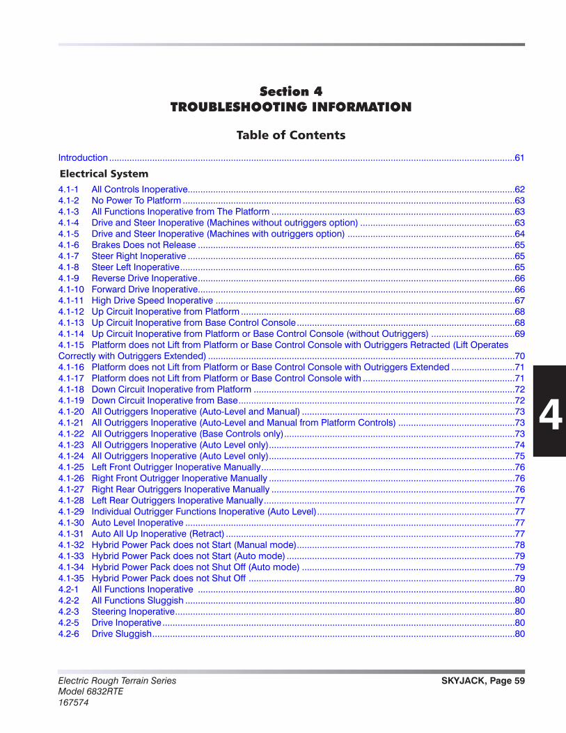
SKYJACK, Page 59Electric Rough Terrain SeriesModel 6832RTE167574
Introduction ................................................................................................................................................................61
Electrical System4.1-1 All Controls Inoperative .................................................................................................................................624.1-2 No Power To Platform ...................................................................................................................................634.1-3 All Functions Inoperative from The Platform ................................................................................................634.1-4 Drive and Steer Inoperative (Machines without outriggers option) .............................................................634.1-5 Drive and Steer Inoperative (Machines with outriggers option) ..................................................................644.1-6 Brakes Does not Release .............................................................................................................................654.1-7 Steer Right Inoperative .................................................................................................................................654.1-8 Steer Left Inoperative ....................................................................................................................................654.1-9 Reverse Drive Inoperative .............................................................................................................................664.1-10 Forward Drive Inoperative .............................................................................................................................664.1-11 High Drive Speed Inoperative ......................................................................................................................674.1-12 Up Circuit Inoperative from Platform ............................................................................................................684.1-13 Up Circuit Inoperative from Base Control Console ......................................................................................684.1-14 Up Circuit Inoperative from Platform or Base Control Console (without Outriggers) .................................694.1-15 Platform does not Lift from Platform or Base Control Console with Outriggers Retracted (Lift Operates Correctly with Outriggers Extended) .........................................................................................................................704.1-16 Platform does not Lift from Platform or Base Control Console with Outriggers Extended .........................714.1-17 Platform does not Lift from Platform or Base Control Console with ............................................................714.1-18 Down Circuit Inoperative from Platform .......................................................................................................724.1-19 Down Circuit Inoperative from Base .............................................................................................................724.1-20 All Outriggers Inoperative (Auto-Level and Manual) ....................................................................................734.1-21 All Outriggers Inoperative (Auto-Level and Manual from Platform Controls) ..............................................734.1-22 All Outriggers Inoperative (Base Controls only) ...........................................................................................734.1-23 All Outriggers Inoperative (Auto Level only) .................................................................................................744.1-24 All Outriggers Inoperative (Auto Level only) .................................................................................................754.1-25 Left Front Outrigger Inoperative Manually ....................................................................................................764.1-26 Right Front Outrigger Inoperative Manually .................................................................................................764.1-27 Right Rear Outriggers Inoperative Manually ................................................................................................764.1-28 Left Rear Outriggers Inoperative Manually ...................................................................................................774.1-29 Individual Outrigger Functions Inoperative (Auto Level) ..............................................................................774.1-30 Auto Level Inoperative ..................................................................................................................................774.1-31 Auto All Up Inoperative (Retract) ..................................................................................................................774.1-32 Hybrid Power Pack does not Start (Manual mode) ......................................................................................784.1-33 Hybrid Power Pack does not Start (Auto mode) ..........................................................................................794.1-34 Hybrid Power Pack does not Shut Off (Auto mode) ....................................................................................794.1-35 Hybrid Power Pack does not Shut Off .........................................................................................................794.2-1 All Functions Inoperative .............................................................................................................................804.2-2 All Functions Sluggish ..................................................................................................................................804.2-3 Steering Inoperative ......................................................................................................................................804.2-5 Drive Inoperative ...........................................................................................................................................804.2-6 Drive Sluggish ...............................................................................................................................................80
4
Section 4TROUBLESHOOTING INFORMATION
Table of Contents

Electric Rough Terrain SeriesModel 6832RTE
167574
SKYJACK, Page 60
Section 4 - Troubleshooting InformationService and Maintenance
Hydraulic System4.2-7 Reverse Drive Inoperative .............................................................................................................................814.2-8 Forward Drive Inoperative .............................................................................................................................814.2-9 Drive Inoperative When in Low Speed Drive ................................................................................................814.2-10 Drive Inoperative When in High Speed Drive ...............................................................................................814.2-11 Brakes Does not Release .............................................................................................................................814.2-12 Up Circuit Inoperative ...................................................................................................................................814.2-13 Down Circuit Inoperative ..............................................................................................................................814.2-14 All Outriggers Inoperative .............................................................................................................................824.2-15 Left Front Outriggers Inoperative ..................................................................................................................824.2-16 Right Front Outriggers Inoperative ...............................................................................................................824.2-17 Right Rear Outriggers Inoperative ................................................................................................................824.2-18 Left Rear Outriggers Inoperative ..................................................................................................................824.2-19 Outriggers Drift In .........................................................................................................................................82General ......................................................................................................................................................................84
Table of Contents (Continued)
SKYJACK, Page 61Electric Rough Terrain SeriesModel 6832RTE167574
Section 4 - Troubleshooting Information Service and Maintenance
Introduction
The following pages contain a table of Troubleshooting Information for locating and correcting most service trouble which can develop. Careful and accurate analysis of the systems listed in the table of Troubleshooting Information will localize the trouble more quickly than any other method. This manual cannot cover all possible troubles and deficiencies that may occur. If a specific trouble is not listed, isolate the major component in which the trouble oc-curs, isolate whether the problem is electrical or hydraulic, and then isolate and correct the specific problem.
The content of this section is separated into probable cause and remedy. The information preceded by a number represents the probable cause. The following line, noted by a dash represents the remedy to the probable cause directly above it. See example below for clarification.
1. Probable Cause - Remedy
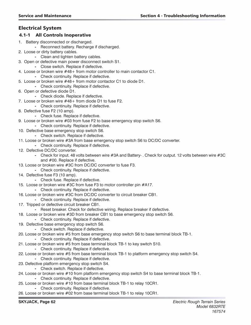
Electric Rough Terrain SeriesModel 6832RTE
167574
SKYJACK, Page 62
Section 4 - Troubleshooting InformationService and Maintenance
Electrical System4.1-1 All Controls Inoperative1. Battery disconnected or discharged.
- Reconnect battery. Recharge if discharged.2. Loose or dirty battery cables.
- Clean and tighten battery cables.3. Open or defective main power disconnect switch S1.
- Close switch. Replace if defective.4. Loose or broken wire #48+ from motor controller to main contactor C1.
- Check continuity. Replace if defective.5. Loose or broken wire #48+ from motor contactor C1 to diode D1.
- Check continuity. Replace if defective.6. Open or defective diode D1.
- Check diode. Replace if defective.7. Loose or broken wire #48+ from diode D1 to fuse F2.
- Check continuity. Replace if defective.8. Defective fuse F2 (10 amp).
- Check fuse. Replace if defective.9. Loose or broken wire #03 from fuse F2 to base emergency stop switch S6.
- Check continuity. Replace if defective.10. Defective base emergency stop switch S6.
- Check switch. Replace if defective.11. Loose or broken wire #3A from base emergency stop switch S6 to DC/DC converter.
- Check continuity. Replace if defective.12. Defective DC/DC converter.
- Check for input. 48 volts between wire #3A and Battery- . Check for output. 12 volts between wire #3C and #00. Replace if defective.
13. Loose or broken wire #3C from DC/DC converter to fuse F3. - Check continuity. Replace if defective.
14. Defective fuse F3 (10 amp). - Check fuse. Replace if defective.
15. Loose or broken wire #3C from fuse F3 to motor controller pin #A17. - Check continuity. Replace if defective.
16. Loose or broken wire #3C from DC/DC converter to circuit breaker CB1. - Check continuity. Replace if defective.
17. Tripped or defective circuit breaker CB1. - Reset breaker. Check for defective wiring. Replace breaker if defective.
18. Loose or broken wire #3D from breaker CB1 to base emergency stop switch S6. - Check continuity. Replace if defective.
19. Defective base emergency stop switch S6. - Check switch. Replace if defective.
20. Loose or broken wire #5 from base emergency stop switch S6 to base terminal block TB-1. - Check continuity. Replace if defective.
21. Loose or broken wire #5 from base terminal block TB-1 to key switch S10. - Check continuity. Replace if defective.
22. Loose or broken wire #5 from base terminal block TB-1 to platform emergency stop switch S4. - Check continuity. Replace if defective.
23. Defective platform emergency stop switch S4. - Check switch. Replace if defective.
24. Loose or broken wire #10 from platform emergency stop switch S4 to base terminal block TB-1. - Check continuity. Replace if defective.
25. Loose or broken wire #10 from base terminal block TB-1 to relay 10CR1. - Check continuity. Replace if defective.
26. Loose or broken wire #02 from base terminal block TB-1 to relay 10CR1.
Electrical System
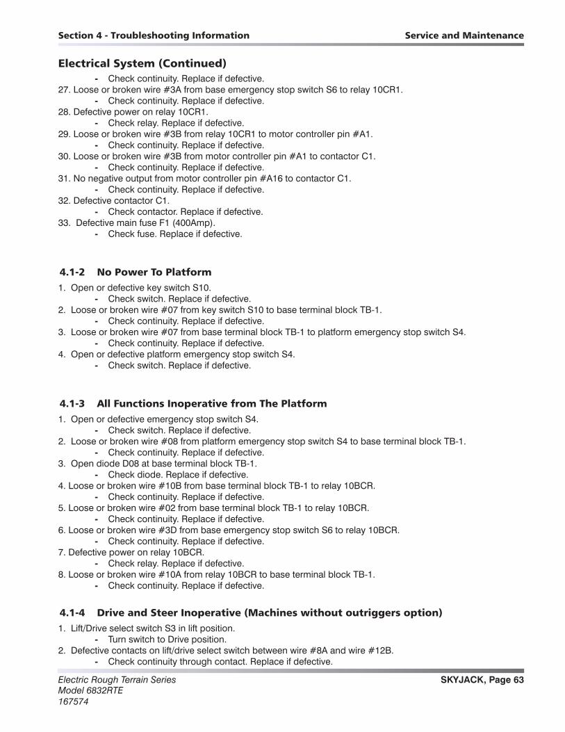
SKYJACK, Page 63Electric Rough Terrain SeriesModel 6832RTE167574
Section 4 - Troubleshooting Information Service and Maintenance
Electrical System (Continued) - Check continuity. Replace if defective.
27. Loose or broken wire #3A from base emergency stop switch S6 to relay 10CR1. - Check continuity. Replace if defective.
28. Defective power on relay 10CR1. - Check relay. Replace if defective.
29. Loose or broken wire #3B from relay 10CR1 to motor controller pin #A1. - Check continuity. Replace if defective.
30. Loose or broken wire #3B from motor controller pin #A1 to contactor C1. - Check continuity. Replace if defective.
31. No negative output from motor controller pin #A16 to contactor C1. - Check continuity. Replace if defective.
32. Defective contactor C1. - Check contactor. Replace if defective.
33. Defective main fuse F1 (400Amp). - Check fuse. Replace if defective.
4.1-2 No Power To Platform1. Open or defective key switch S10.
- Check switch. Replace if defective.2. Loose or broken wire #07 from key switch S10 to base terminal block TB-1.
- Check continuity. Replace if defective.3. Loose or broken wire #07 from base terminal block TB-1 to platform emergency stop switch S4.
- Check continuity. Replace if defective.4. Open or defective platform emergency stop switch S4.
- Check switch. Replace if defective.
4.1-3 All Functions Inoperative from The Platform1. Open or defective emergency stop switch S4.
- Check switch. Replace if defective.2. Loose or broken wire #08 from platform emergency stop switch S4 to base terminal block TB-1.
- Check continuity. Replace if defective.3. Open diode D08 at base terminal block TB-1.
- Check diode. Replace if defective.4. Loose or broken wire #10B from base terminal block TB-1 to relay 10BCR.
- Check continuity. Replace if defective.5. Loose or broken wire #02 from base terminal block TB-1 to relay 10BCR.
- Check continuity. Replace if defective.6. Loose or broken wire #3D from base emergency stop switch S6 to relay 10BCR.
- Check continuity. Replace if defective.7. Defective power on relay 10BCR.
- Check relay. Replace if defective.8. Loose or broken wire #10A from relay 10BCR to base terminal block TB-1.
- Check continuity. Replace if defective.
4.1-4 Drive and Steer Inoperative (Machines without outriggers option)1. Lift/Drive select switch S3 in lift position.
- Turn switch to Drive position.2. Defective contacts on lift/drive select switch between wire #8A and wire #12B.
- Check continuity through contact. Replace if defective.

Electric Rough Terrain SeriesModel 6832RTE
167574
SKYJACK, Page 64
Section 4 - Troubleshooting InformationService and Maintenance
Electrical System (Continued)3. Loose or broken wire #08 or #02 from platform emergency stop switch S4 to joystick controller S7.
- Check continuity. Replace if defective.4. Defective joystick controller enable switch S7-6.
- Check switch. Replace if defective.5. Defective joystick controller neutral switch S7-1.
- Check switch. Replace if defective.6. Loose or broken wire #12B from lift/drive switch S3 to steer switches S7-2 and S7-3.
- Check continuity. Replace if defective.7. Open diode D12B.
- Check diode. Replace if defective.8. Loose or broken wire #10A from base terminal block to tilt switch TS1.
- Check continuity. Replace if defective.9. Defective tilt switch TS1.
- Check tilt switch. Replace if defective.10. Loose or broken wire #28 from tilt switch TS1 to terminal block TB1.
- Check continuity. Replace if defective.11. Loose or broken wire #28 from base terminal TB1 to outrigger connector CN14 at pin #7.
- Check continuity. Replace if defective.12. Loose or broken jumper wire from #28 to # 28A on outrigger connector CN14 between pin #1 and pin #7.
- Check continuity. Replace if defective.13. Loose or broken wire #28A from outrigger connector CN14 at pin #1 to base terminal block TB1.
- Check continuity. Replace if defective.14. No output or broken wire #59 from joystick card to motor controller pin #A3. (Drive only)
- Check continuity. Replace if defective.
4.1-5 Drive and Steer Inoperative (Machines with outriggers option)1. Outriggers not fully retracted
- Fully retract outrigger cylinders2. Lift/Drive select switch S3 in lift position.
- Turn switch to Drive position.3. Defective contacts on lift/drive select switch between wire #8A and wire #12B.
- Check continuity through contact. Replace if defective.4. Loose or broken wire #08 or #02 from platform emergency stop switch S4 to joystick controller S7.
- Check continuity. Replace if defective.5. Defective joystick controller enable switch S7-6.
- Check switch. Replace if defective.6. Defective joystick controller neutral switch S7-1.
- Check switch. Replace if defective.7. Loose or broken wire #12B from lift/drive switch S3 to steer switches S7-2 and S7-3.
- Check continuity. Replace if defective.8. Open diode D12B.
- Check diode. Replace if defective.9. Loose or broken wire #10A from base terminal block TB1 to outrigger control module OCM1 at pin #P2-12.
- Check continuity. Replace if defective.10. Loose or broken wire #28 from outrigger control module OCM1 at pin #P2-9 to outrigger connector CN14 at pin #7.
- Check continuity. Replace if defective.

SKYJACK, Page 65Electric Rough Terrain SeriesModel 6832RTE167574
Section 4 - Troubleshooting Information Service and Maintenance
Electrical System (Continued)11. Left rear outrigger limit switch LS64 is out of adjustment or defective.
- Check continuity through switch. Adjust switch if out of adjustment. Replace if defective.12. Right rear outrigger limit switch LS63 is out of adjustment or defective.
- Check continuity through switch. Adjust switch if out of adjustment. Replace if defective.13. Right front outrigger limit switch LS62 is out of adjustment or defective.
- Check continuity through switch. Adjust switch if out of adjustment. Replace if defective.14. Left front outrigger limit switch LS61 is out of adjustment or defective.
- Check continuity through switch. Adjust switch if out of adjustment. Replace if defective.15. Defective drive enable relay 61CR.
- Check relay. Replace if defective.
4.1-6 Brakes Does not Release1. Loose or broken wire #30 from base terminal block TB1 to brake valve coil 3H-30.
- Check continuity. Replace if defective.2. Defective brake valve coil 3H-30.
- Check continuity through coil. Replace if defective.3. Loose or broken wire #02 from brake valve 3H-30 to base terminal block TB1.
- Check continuity. Replace if defective.
4.1-7 Steer Right Inoperative1. Defective steer right switch S7-3 in controller S7.
- Check switch. Replace if defective.2. Loose or broken wire #23 from steer right switch S7-3 to base terminal block TB1.
- Check continuity. Replace if defective.3. Loose or broken wire #23 from base terminal block TB1 to steer right valve coil 4H-23.
- Check continuity. Replace if defective.4. Defective steer right valve coil 4H-23.
- Check coil. Replace if defective.5. Loose or broken wire #02 from steer right valve coil 4H-23 to base terminal block TB1.
- Check continuity. Replace if defective.6. Open diode D23.
- Check diode. Replace if defective.7. Loose or broken wire #30A from base terminal block TB1 to relay 30CR.
- Check continuity. Replace if defective.8. Defective steer enable relay 30CR.
- Check relay. Replace if defective.9. Loose or broken wire #30B from relay 30CR to base terminal block TB1.
- Check continuity. Replace if defective.10. Loose or broken wire #30B from base terminal block TB1 to motor controller pin #B6.
- Check continuity. Replace if defective.
4.1-8 Steer Left Inoperative1. Defective steer left switch S7-2 in controller S7.
- Check switch. Replace if defective.2. Loose or broken wire #24 from steer left switch S7-2 to base terminal block TB1.
- Check continuity. Replace if defective.3. Loose or broken wire #24 from base terminal block TB1 to steer left valve coil 4H-24.
- Check continuity. Replace if defective.4. Defective steer left valve coil 4H-24.
- Check coil. Replace if defective.

Electric Rough Terrain SeriesModel 6832RTE
167574
SKYJACK, Page 66
Section 4 - Troubleshooting InformationService and Maintenance
Electrical System (Continued)5. Loose or broken wire #02 from steer left valve coil 4H-24 to base terminal block TB1.
- Check continuity. Replace if defective.6. Open diode D24.
- Check diode. Replace if defective.7. Loose or broken wire #30A from base terminal block TB1 to relay 30CR.
- Check continuity. Replace if defective.8. Defective steer enable relay 30CR.
- Check relay. Replace if defective.9. Loose or broken wire #30B from relay 30CR to base terminal block TB1.
- Check continuity. Replace if defective.10. Loose or broken wire #30B from base terminal block TB1 to motor controller pin #B6.
- Check continuity. Replace if defective.
4.1-9 Reverse Drive Inoperative1. Defective contacts on lift/drive select switch between wire #A and wire #15.
- Check continuity through contact. Replace if defective.2. Defective controller S7.
- Check controller. Replace if defective.3. No output or broken wire #A from joystick card to contacts on Lift/Drive select switch between wire #A and wire #15.
- Check continuity. Replace if defective.4. Loose or broken wire #15 from Lift/Drive select switch S3 to reverse valve coil 4H-15.
- Check continuity. Replace if defective.5. Loose or broken wire #02 from reverse valve coil 4H-15 to base terminal block TB1.
- Check continuity. Replace if defective.6. Loose or broken wire #15 from base terminal block TB1 to relay 20ACR1 (In parallel drive only).
- Check continuity. Replace if defective.7. Defective relay 20ACR1 (in parallel drive only).
- Check relay. Replace if defective.8. Loose or broken wire #15A from relay 20ACR1 to parallel reverse valve coil 4H-15A (in parallel drive only).
- Check continuity. Replace if defective.9. Loose or broken wire #02 from base terminal block TB1 to parallel reverse valve coil 4H-15A (in parallel drive only).
- Check continuity. Replace if defective.10. Defective parallel reverse valve coil 4H-15A (in parallel drive only).
- Check coil. Replace if defective.11. Open diode D15, D15A or D30.
- Check diodes. Replace if defective.
4.1-10 Forward Drive Inoperative1. Defective contacts on lift/drive select switch between wire #A and wire #16.
- Check continuity through contact. Replace if defective.2. Defective controller S7.
- Check controller. Replace if defective.3. No output or broken wire #B from joystick card to contacts on Lift/Drive select switch between wire #B and wire #16.
- Check continuity. Replace if defective.4. Loose or broken wire #16 from Lift/Drive select switch S3 to forward valve coil 4H-16.
- Check continuity. Replace if defective.
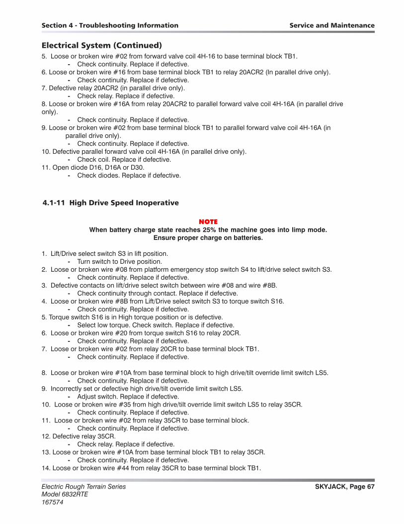
SKYJACK, Page 67Electric Rough Terrain SeriesModel 6832RTE167574
Section 4 - Troubleshooting Information Service and Maintenance
Electrical System (Continued)5. Loose or broken wire #02 from forward valve coil 4H-16 to base terminal block TB1.
- Check continuity. Replace if defective.6. Loose or broken wire #16 from base terminal block TB1 to relay 20ACR2 (In parallel drive only).
- Check continuity. Replace if defective.7. Defective relay 20ACR2 (in parallel drive only).
- Check relay. Replace if defective.8. Loose or broken wire #16A from relay 20ACR2 to parallel forward valve coil 4H-16A (in parallel drive only).
- Check continuity. Replace if defective.9. Loose or broken wire #02 from base terminal block TB1 to parallel forward valve coil 4H-16A (in parallel drive only).
- Check continuity. Replace if defective.10. Defective parallel forward valve coil 4H-16A (in parallel drive only).
- Check coil. Replace if defective.11. Open diode D16, D16A or D30.
- Check diodes. Replace if defective.
4.1-11 High Drive Speed Inoperative
NOTEWhen battery charge state reaches 25% the machine goes into limp mode.
Ensure proper charge on batteries.
1. Lift/Drive select switch S3 in lift position. - Turn switch to Drive position.
2. Loose or broken wire #08 from platform emergency stop switch S4 to lift/drive select switch S3. - Check continuity. Replace if defective.
3. Defective contacts on lift/drive select switch between wire #08 and wire #8B. - Check continuity through contact. Replace if defective.
4. Loose or broken wire #8B from Lift/Drive select switch S3 to torque switch S16. - Check continuity. Replace if defective.
5. Torque switch S16 is in High torque position or is defective. - Select low torque. Check switch. Replace if defective.
6. Loose or broken wire #20 from torque switch S16 to relay 20CR. - Check continuity. Replace if defective.
7. Loose or broken wire #02 from relay 20CR to base terminal block TB1. - Check continuity. Replace if defective.
8. Loose or broken wire #10A from base terminal block to high drive/tilt override limit switch LS5. - Check continuity. Replace if defective.
9. Incorrectly set or defective high drive/tilt override limit switch LS5. - Adjust switch. Replace if defective.
10. Loose or broken wire #35 from high drive/tilt override limit switch LS5 to relay 35CR. - Check continuity. Replace if defective.
11. Loose or broken wire #02 from relay 35CR to base terminal block. - Check continuity. Replace if defective.
12. Defective relay 35CR. - Check relay. Replace if defective.
13. Loose or broken wire #10A from base terminal block TB1 to relay 35CR. - Check continuity. Replace if defective.
14. Loose or broken wire #44 from relay 35CR to base terminal block TB1.
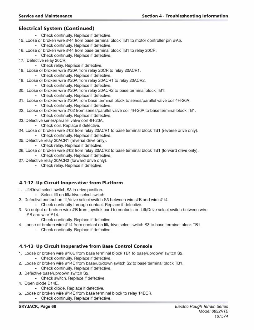
Electric Rough Terrain SeriesModel 6832RTE
167574
SKYJACK, Page 68
Section 4 - Troubleshooting InformationService and Maintenance
Electrical System (Continued) - Check continuity. Replace if defective.
15. Loose or broken wire #44 from base terminal block TB1 to motor controller pin #A5. - Check continuity. Replace if defective.
16. Loose or broken wire #44 from base terminal block TB1 to relay 20CR. - Check continuity. Replace if defective.
17. Defective relay 20CR. - Check relay. Replace if defective.
18. Loose or broken wire #20A from relay 20CR to relay 20ACR1. - Check continuity. Replace if defective.
19. Loose or broken wire #20A from relay 20ACR1 to relay 20ACR2. - Check continuity. Replace if defective.
20. Loose or broken wire #20A from relay 20ACR2 to base terminal block TB1. - Check continuity. Replace if defective.
21. Loose or broken wire #20A from base terminal block to series/parallel valve coil 4H-20A. - Check continuity. Replace if defective.
22. Loose or broken wire #02 from series/parallel valve coil 4H-20A to base terminal block TB1. - Check continuity. Replace if defective.
23. Defective series/parallel valve coil 4H-20A. - Check coil. Replace if defective.
24. Loose or broken wire #02 from relay 20ACR1 to base terminal block TB1 (reverse drive only). - Check continuity. Replace if defective.
25. Defective relay 20ACR1 (reverse drive only). - Check relay. Replace if defective.
26. Loose or broken wire #02 from relay 20ACR2 to base terminal block TB1 (forward drive only). - Check continuity. Replace if defective.
27. Defective relay 20ACR2 (forward drive only). - Check relay. Replace if defective.
4.1-12 Up Circuit Inoperative from Platform1. Lift/Drive select switch S3 in drive position.
- Select lift on lift/drive select switch.2. Defective contact on lift/drive select switch S3 between wire #B and wire #14.
- Check continuity through contact. Replace if defective.3. No output or broken wire #B from joystick card to contacts on Lift/Drive select switch between wire #B and wire #14.
- Check continuity. Replace if defective.4. Loose or broken wire #14 from contact on lift/drive select switch S3 to base terminal block TB1.
- Check continuity. Replace if defective.
4.1-13 Up Circuit Inoperative from Base Control Console1. Loose or broken wire #10E from base terminal block TB1 to base/up/down switch S2.
- Check continuity. Replace if defective.2. Loose or broken wire #14E from base/up/down switch S2 to base terminal block TB1.
- Check continuity. Replace if defective.3. Defective base/up/down switch S2.
- Check switch. Replace if defective.4. Open diode D14E.
- Check diode. Replace if defective.5. Loose or broken wire #14E from base terminal block to relay 14ECR.
- Check continuity. Replace if defective.
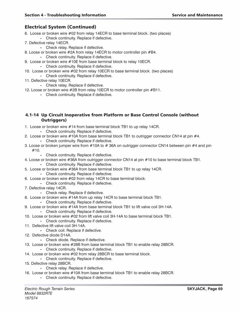
SKYJACK, Page 69Electric Rough Terrain SeriesModel 6832RTE167574
Section 4 - Troubleshooting Information Service and Maintenance
Electrical System (Continued)6. Loose or broken wire #02 from relay 14ECR to base terminal block. (two places)
- Check continuity. Replace if defective.7. Defective relay 14ECR.
- Check relay. Replace if defective.8. Loose or broken wire #2A from relay 14ECR to motor controller pin #B4.
- Check continuity. Replace if defective.9. Loose or broken wire #10E from base terminal block to relay 10ECR.
- Check continuity. Replace if defective.10. Loose or broken wire #02 from relay 10ECR to base terminal block. (two places)
- Check continuity. Replace if defective.11. Defective relay 10ECR.
- Check relay. Replace if defective.12. Loose or broken wire #2B from relay 10ECR to motor controller pin #B11.
- Check continuity. Replace if defective.
4.1-14 Up Circuit Inoperative from Platform or Base Control Console (without Outriggers)
1. Loose or broken wire #14 from base terminal block TB1 to up relay 14CR. - Check continuity. Replace if defective.
2. Loose or broken wire #10A from base terminal block TB1 to outrigger connector CN14 at pin #4. - Check continuity. Replace if defective.
3. Loose or broken jumper wire from #10A to # 36A on outrigger connector CN14 between pin #4 and pin #10.
- Check continuity. Replace if defective.4. Loose or broken wire #36A from outrigger connector CN14 at pin #10 to base terminal block TB1.
- Check continuity. Replace if defective.5. Loose or broken wire #36A from base terminal block TB1 to up relay 14CR.
- Check continuity. Replace if defective.6. Loose or broken wire #02 from relay 14CR to base terminal block.
- Check continuity. Replace if defective.7. Defective relay 14CR.
- Check relay. Replace if defective.8. Loose or broken wire #14A from up relay 14CR to base terminal block TB1.
- Check continuity. Replace if defective.9. Loose or broken wire #14A from base terminal block TB1 to lift valve coil 3H-14A.
- Check continuity. Replace if defective.10. Loose or broken wire #02 from lift valve coil 3H-14A to base terminal block TB1.
- Check continuity. Replace if defective.11. Defective lift valve coil 3H-14A.
- Check coil. Replace if defective.12. Defective diode D14A.
- Check diode. Replace if defective.13. Loose or broken wire #28B from base terminal block TB1 to enable relay 28BCR.
- Check continuity. Replace if defective.14. Loose or broken wire #02 from relay 28BCR to base terminal block.
- Check continuity. Replace if defective.15. Defective relay 28BCR.
- Check relay. Replace if defective.16. Loose or broken wire #10A from base terminal block TB1 to enable relay 28BCR.
- Check continuity. Replace if defective.

Electric Rough Terrain SeriesModel 6832RTE
167574
SKYJACK, Page 70
Section 4 - Troubleshooting InformationService and Maintenance
Electrical System (Continued)17. Loose or broken wire #21 from enable relay 28BCR to enable relay 28CR.
- Check continuity. Replace if defective.18. No output on wire #28 from tilt switch to base terminal block TB1.
- Check tilt switch. Reset if required. Replace if defective.19. Loose or broken wire #28 from base terminal block TB1 to enable relay 28CR.
- Check continuity. Replace if defective.20. Loose or broken wire #02 from relay 28CR to base terminal block.
- Check continuity. Replace if defective.21. Defective relay 28CR.
- Check relay. Replace if defective.22. Loose or broken wire #21A from enable relay 28CR to base terminal block TB1.
- Check continuity. Replace if defective.23. Loose or broken wire #21A from base terminal block TB1 to dump valve coils 2H-21A and 2H-21A-1.
- Check continuity. Replace if defective.24. Loose or broken wire #02 from dump valve coils 2H-21A and 2H-21A-1 to base terminal block TB1.
- Check continuity. Replace if defective.25. Defective dump valve coils 2H-21A and 2H-21A-1.
- Check coil. Replace if defective.
4.1-15 Platform does not Lift from Platform or Base Control Console with Outriggers Retracted (Lift Operates Correctly with Outriggers Extended)
1. Outriggers not fully retracted. - Fully retract outrigger cylinders.
2. Loose or broken wire #10A from base terminal block TB1 to pin #4 on connector CN14 at the outrigger board.
- Check continuity. Replace if defective.3. Loose or broken wire #10A from outrigger board to outrigger limit switch LS64.
- Check continuity. Replace if defective.4. Defective outrigger limit switch LS64.
- Check switch. Replace if defective.5. Loose or broken wire #64 from outrigger limit switch LS64 to outrigger board.
- Check continuity. Replace if defective.6. Loose or broken wire #64 from outrigger board to outrigger limit switch LS63.
- Check continuity. Replace if defective.7. Defective outrigger limit switch LS63.
- Check continuity. Replace if defective.8. Loose or broken wire #63 from outrigger limit switch LS63 to outrigger board.
- Check continuity. Replace if defective.9. Loose or broken wire #63 from outrigger board to outrigger limit switch LS62.
- Check continuity. Replace if defective.10. Defective Limit Switch LS62.
- Check switch. Replace if defective.11. Loose or broken wire #62 from outrigger limit switch LS62 to outrigger board.
- Check continuity. Replace if defective.12. Loose or broken wire #62 from outrigger board to outrigger limit switch LS61.
- Check continuity. Replace if defective.13. Defective outrigger limit switch LS61.
- Check switch. Replace if defective.14. Loose or broken wire #36 from outrigger limit switch LS61 to outrigger board.
- Check continuity. Replace if defective.15. Open diode D36 on outrigger board.
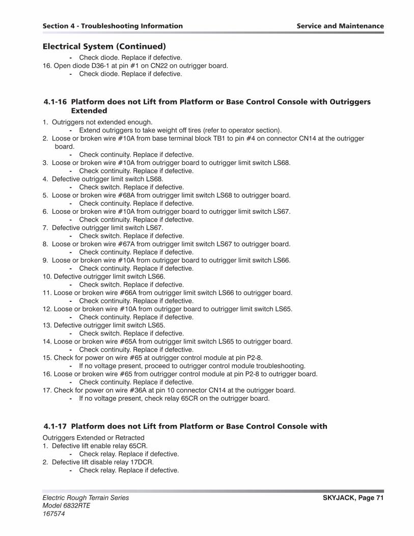
SKYJACK, Page 71Electric Rough Terrain SeriesModel 6832RTE167574
Section 4 - Troubleshooting Information Service and Maintenance
Electrical System (Continued) - Check diode. Replace if defective.
16. Open diode D36-1 at pin #1 on CN22 on outrigger board. - Check diode. Replace if defective.
4.1-16 Platform does not Lift from Platform or Base Control Console with Outriggers Extended
1. Outriggers not extended enough. - Extend outriggers to take weight off tires (refer to operator section).
2. Loose or broken wire #10A from base terminal block TB1 to pin #4 on connector CN14 at the outrigger board.
- Check continuity. Replace if defective.3. Loose or broken wire #10A from outrigger board to outrigger limit switch LS68.
- Check continuity. Replace if defective.4. Defective outrigger limit switch LS68.
- Check switch. Replace if defective.5. Loose or broken wire #68A from outrigger limit switch LS68 to outrigger board.
- Check continuity. Replace if defective.6. Loose or broken wire #10A from outrigger board to outrigger limit switch LS67.
- Check continuity. Replace if defective.7. Defective outrigger limit switch LS67.
- Check switch. Replace if defective.8. Loose or broken wire #67A from outrigger limit switch LS67 to outrigger board.
- Check continuity. Replace if defective.9. Loose or broken wire #10A from outrigger board to outrigger limit switch LS66.
- Check continuity. Replace if defective.10. Defective outrigger limit switch LS66.
- Check switch. Replace if defective.11. Loose or broken wire #66A from outrigger limit switch LS66 to outrigger board.
- Check continuity. Replace if defective.12. Loose or broken wire #10A from outrigger board to outrigger limit switch LS65.
- Check continuity. Replace if defective.13. Defective outrigger limit switch LS65.
- Check switch. Replace if defective.14. Loose or broken wire #65A from outrigger limit switch LS65 to outrigger board.
- Check continuity. Replace if defective.15. Check for power on wire #65 at outrigger control module at pin P2-8.
- If no voltage present, proceed to outrigger control module troubleshooting.16. Loose or broken wire #65 from outrigger control module at pin P2-8 to outrigger board.
- Check continuity. Replace if defective.17. Check for power on wire #36A at pin 10 connector CN14 at the outrigger board.
- If no voltage present, check relay 65CR on the outrigger board.
4.1-17 Platform does not Lift from Platform or Base Control Console withOutriggers Extended or Retracted1. Defective lift enable relay 65CR.
- Check relay. Replace if defective.2. Defective lift disable relay 17DCR.
- Check relay. Replace if defective.
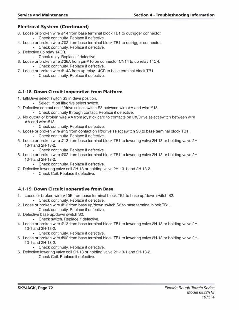
Electric Rough Terrain SeriesModel 6832RTE
167574
SKYJACK, Page 72
Section 4 - Troubleshooting InformationService and Maintenance
Electrical System (Continued)3. Loose or broken wire #14 from base terminal block TB1 to outrigger connector.
- Check continuity. Replace if defective.4. Loose or broken wire #02 from base terminal block TB1 to outrigger connector.
- Check continuity. Replace if defective.5. Defective up relay 14CR.
- Check relay. Replace if defective.6. Loose or broken wire #36A from pin#10 on connector CN14 to up relay 14CR.
- Check continuity. Replace if defective.7. Loose or broken wire #14A from up relay 14CR to base terminal block TB1.
- Check continuity. Replace if defective.
4.1-18 Down Circuit Inoperative from Platform1. Lift/Drive select switch S3 in drive position.
- Select lift on lift/drive select switch.2. Defective contact on lift/drive select switch S3 between wire #A and wire #13.
- Check continuity through contact. Replace if defective.3. No output or broken wire #A from joystick card to contacts on Lift/Drive select switch between wire #A and wire #13.
- Check continuity. Replace if defective.4. Loose or broken wire #13 from contact on lift/drive select switch S3 to base terminal block TB1.
- Check continuity. Replace if defective.5. Loose or broken wire #13 from base terminal block TB1 to lowering valve 2H-13 or holding valve 2H- 13-1 and 2H-13-2.
- Check continuity. Replace if defective.6. Loose or broken wire #02 from base terminal block TB1 to lowering valve 2H-13 or holding valve 2H- 13-1 and 2H-13-2.
- Check continuity. Replace if defective.7. Defective lowering valve coil 2H-13 or holding valve 2H-13-1 and 2H-13-2.
- Check Coil. Replace if defective.
4.1-19 Down Circuit Inoperative from Base1. Loose or broken wire #10E from base terminal block TB1 to base up/down switch S2.
- Check continuity. Replace if defective.2. Loose or broken wire #13 from base up/down switch S2 to base terminal block TB1.
- Check continuity. Replace if defective.3. Defective base up/down switch S2.
- Check switch. Replace if defective.4. Loose or broken wire #13 from base terminal block TB1 to lowering valve 2H-13 or holding valve 2H- 13-1 and 2H-13-2.
- Check continuity. Replace if defective.5. Loose or broken wire #02 from base terminal block TB1 to lowering valve 2H-13 or holding valve 2H- 13-1 and 2H-13-2.
- Check continuity. Replace if defective.6. Defective lowering valve coil 2H-13 or holding valve 2H-13-1 and 2H-13-2.
- Check Coil. Replace if defective.
SKYJACK, Page 73Electric Rough Terrain SeriesModel 6832RTE167574
Section 4 - Troubleshooting Information Service and Maintenance
Electrical System (Continued)4.1-20 All Outriggers Inoperative (Auto-Level and Manual)
WARNINGScissors lift must be below high speed limit switch for outriggers to function.
NOTEFor the outriggers to function the upper control box must be in the lift position
and the scissor stack stowed or fully retracted.
1. Loose or broken wire # 44 from base terminal block TB1 to pin #6 on connector CN14 on outrigger board.
- Check for continuity. Replace if defective.2. No power at wire #9 at pin #5 on connector CN14 on outrigger board.
- If no power is present check for continuity on wire #9 back to the main terminal block TB1.Replace if defective.
3. Defective relay 9CR2 or 9CR3 on outrigger board. - Check relays. Replace if defective.
4. Open diode D17C-1 on outrigger board. - Check diode. Replace if defective.
5. Defective relay 17DCR on outrigger board. - Check relay. Replace if defective.
6. Open or defective fuse jumper J17E on outrigger board. - Check fuse. Replace if defective.
7. Loose or broken wire # 17A from pin #2 on connector CN14 on outrigger board to terminal block TB1. - Check for continuity. Replace if defective.
8. Loose or broken wire #17C at pin #1 or wire #02 at pin #2 on connector CN21 on outrigger board to outrigge holding valve coil 2H-17C.
- Check for continuity. Replace if defective.9. Defective outrigger holding valve coil 2H-17C.
- Check coil. Replace if defective.10. Loose or broken wire #17C from outrigger board connector CN14 pin 2 to motor controller pin #B13.
- Check continuity. Replace if defective.
4.1-21 All Outriggers Inoperative (Auto-Level and Manual from Platform Controls)1. Loose or broken wires #35C at pin #1 on connector CN20 on outrigger board through outrigger cables and plugs to the outrigger enable switch S9A in the control box.
- Check for continuity. Replace if defective.2. Loose or broken wire #35D from outrigger enable switch S9A to pin #5 on the outrigger control console plug.
- Check for continuity. Replace if defective.3. Defective outrigger enable switch S9A.
- Check switch. Replace if defective.
4.1-22 All Outriggers Inoperative (Base Controls only)1. Defective outrigger enable switch S9B.
- Check switch. Replace if defective.

Electric Rough Terrain SeriesModel 6832RTE
167574
SKYJACK, Page 74
Section 4 - Troubleshooting InformationService and Maintenance
Electrical System (Continued)4.1-23 All Outriggers Inoperative (Auto Level only)A: Led Power Indicator Light at Outrigger Control Module (OCM1) Not On (Constant)1. Loose or broken wire #10A at pin #1 of the tilt switch connector to pin P2-12 on the outrigger control module
OCM1. - Check for continuity. Replace if defective.
2. Loose or broken wire #10A at pin #1 of the tilt switch connector to base terminal block TB1. - Check for continuity. Replace if defective.
3. Loose or broken wire # 02 at pin #3 of the tilt switch connector to pin P2-11 on the outrigger control module OCM1.
- Check for continuity. Replace if defective.4. Loose or broken wire #02 at pin #3 of the tilt switch connector to base terminal block TB1.
- Check for continuity. Replace if defective.5. Defective outrigger control module OCM1.
- Replace.

SKYJACK, Page 75Electric Rough Terrain SeriesModel 6832RTE167574
Section 4 - Troubleshooting Information Service and Maintenance
Electrical System (Continued)
4.1-24 All Outriggers Inoperative (Auto Level only) B: Led Power Indicator Light at Outrigger Control Module (OCM1) Flashing
Flash Code Probable Cause Remedy
1/1 1. Outriggers are all up and machine is tilted.
1. Level the machine.
1/2 1. Machine is elevated. 2. Loose or broken wire # 35.
1. Lower the scissor stack below high speed limit switch. 2. Check for input voltage on wire #35 at pin P2-10 of the outrigger
control module (OCM1). Replace if defective.
2/2
1. At least one outrigger is not fully retracted.
2. Defective outrigger rod limit switch (LS61, LS62, LS63, LS64) or wiring.
3. Defective diode (D36) on outrigger board.
1. Fully retract all outriggers. 2. Replace defective or damaged switch(es) or wiring. 3. Check for continuity. Replace if defective.
2/1 1. Outriggers are all down and the machine is not fully level.
1. Move machine to less sloped terrain if it will not lift.
5/5
1. Power on wire #70 or #79 at power on. 2. Power on wire #70 or #79 when
manually operating outriggers.
1. Check for power on wire #70 or #79 at pin P2-5 or P2-6 of the outrigger control module. Replace defective component.
2. Check for power on wire #70 or #79 while manually operating an outrigger.
5/2 1. Low or no voltage on wire #35c. 2. Loose or broken wire on #35c.
1. Check battery and charging system to ensure minimum 9 volts. 2. Check for input voltage on wire #35c at pin P4-9 of outrigger
control module (OCM1).
7/1 1. Excessive vibration. 2. Defective outrigger control module.
1. Outrigger control module cannot read tilt sensor. 2. Replace.
6/6 1. Outriggers are being manually controlled.
1. Indicates function activated. No repair necessary.
7/8 1. Error occured while self diagnosing the
hardware fail safe. 1. Turn off power to reset the outrigger control module. Turn power
back on and see if the code has cleared. If problem persists, replace outrigger control module.
5/1 1. Low input voltage to outrigger control module.
1. Check for minimum 9 volts between wire #02 at pin P2-11 and wire #10A at pin P2-12 at outrigger control module.
7/7 1. Startup error occurred while self
diagnosing. 1. Turn off power to reset the outrigger control module. Turn power
back on and see if the code has cleared. If problem persists, replace outrigger control module.
7/5 1. Internal failure of OCM1. 1. Turn off power to reset the outrigger control module. Turn power
back on and see if the code has cleared. If problem persists, replace outrigger control module.
7/2 1. Internal failure of OCM1. 1. Turn off power to reset the outrigger control module. Turn power
back on and see if the code has cleared. If problem persists, replace outrigger control module.
8/1 1. Internal failure of OCM1. 1. Turn off power to reset the outrigger control module. Turn power
back on and see if the code has cleared. If problem persists, replace outrigger control module.
8/2 1. Internal failure of OCM1. 1. Turn off power to reset the outrigger control module. Turn power
back on and see if the code has cleared. If problem persists, replace outrigger control module.
8/3 1. Internal failure of OCM1. 1. Turn off power to reset the outrigger control module. Turn power
back on and see if the code has cleared. If problem persists, replace outrigger control module.
8/4 1. Internal failure of OCM1. 1. Turn off power to reset the outrigger control module. Turn power
back on and see if the code has cleared. If problem persists, replace outrigger control module.
8/5 1. Internal failure of OCM1. 1. Turn off power to reset the outrigger control module. Turn power
back on and see if the code has cleared. If problem persists, replace outrigger control module.
7/6 1. Internal failure of OCM1. 1. Turn off power to reset the outrigger control module. Turn power
back on and see if the code has cleared. If problem persists, replace outrigger control module.
60416AB
Electric Rough Terrain SeriesModel 6832RTE
167574
SKYJACK, Page 76
Section 4 - Troubleshooting InformationService and Maintenance
Electrical System (Continued)4.1-25 Left Front Outrigger Inoperative Manually1. Defective left front outrigger switch S20 at platform control console or S20A at base control console.
- Check switch. Replace if defective.2. Loose or broken wire #71(up) from outrigger control console to pin #6 (up) on connector CN20 at outrigger
board, or wire #75 (down) to pin #7 (down). - Check continuity. Replace if defective.
3. Open diode D71 (up) or D75 (down) on outrigger board. - Check diode. Replace if defective.
4. Loose or broken wire #71(up) at pin #7 (up) or pin #75 (down) at pin #8 (down) on connector CN21 at outrigger board to valve coil 4H71 (up) or 4H75 (down).
- Check continuity. Replace if defective.5. Loose or broken wire #02 from valve coil 4H71 (up) or 4H75 (down) to pin #2 on connector CN21 at the outrigger board.
- Check continuity. Replace if defective.
4.1-26 Right Front Outrigger Inoperative Manually1. Defective right front outrigger switch S21 at platform control console or S21A at base control console.
- Check switch. Replace if defective.2. Loose or broken wire #72 (up) from outrigger control console to pin #8 (up) on connector CN20 at outrigger
board, or wire #76 (down) to pin #9 (down). - Check continuity. Replace if defective.
3. Open diode D72 (up) or D76 (down) on outrigger board. - Check diode. Replace if defective.
4. Loose or broken wire #72 (up) at pin #9 (up) or wire #76 (down) at pin #10 (down) on connector CN21 at outrigger board to valve coil 4H72 (up) or 4H76 (down).
- Check continuity. Replace if defective.5. Loose or broken wire #02 from valve coil 4H72 (up) or 4H76 (down) to pin #2 on connector CN21 at the outrigger board.
- Check continuity. Replace if defective.
4.1-27 Right Rear Outriggers Inoperative Manually1. Defective right rear outrigger switch S22 at platform control console or S22A at base control console.
- Check switch. Replace if defective.2. Loose or broken wire #73(up) from outrigger control console to pin #3 (up) on connector CN20 at outrigger
board, or wire #77 (down) to pin #4 (down). - Check continuity. Replace if defective.
3. Open diode D73 (up) or D77 (down) on outrigger board. - Check diode. Replace if defective.
4. Loose or broken wire #73(up) at pin #4 (up) or wire #77 (down) at pin #5 (down) on connector CN21 at outrigger board to valve coil 4H73 (up) or 4H77 (down).
- Check continuity. Replace if defective.5. Loose or broken wire #02 from valve coil 4H73 (up) or 4H77 (down) to pin #2 on connector CN21 at the outrigger board.
- Check continuity. Replace if defective.
SKYJACK, Page 77Electric Rough Terrain SeriesModel 6832RTE167574
Section 4 - Troubleshooting Information Service and Maintenance
Electrical System (Continued)4.1-28 Left Rear Outriggers Inoperative Manually1. Defective left rear outrigger switch S23 at platform control console or S23A at base control console.
- Check switch. Replace if defective.2. Loose or broken wire #74 (up) from outrigger control console to pin #5 (up) on connector CN20 at outrigger
board, or #78 (down) from pin #2 (down). - Check continuity. Replace if defective.
3. Open diode D74 (up) or D78 (down) on outrigger board. - Check diode. Replace if defective.
4. Loose or broken wire #74(up) at pin #6 (up) or wire #78 (down) at pin #3 (down) on connector CN21 at outrigger board to valve coil 4H74 (up) or 4H78 (down).
- Check continuity. Replace if defective.5. Loose or broken wire #02 from valve coil 4H74 (up) or 4H78 (down) to pin #2 on connector CN21 at the outrigger board.
- Check continuity. Replace if defective.
4.1-29 Individual Outrigger Functions Inoperative (Auto Level)1. Loose or broken wire #71 #75 (depending on function not working) at outrigger control module plug P4 pins 18.
- Check connections of outrigger functions not working (refer to Section 5 for pin reference chart). Replace if defective.
2. No output from outrigger control module OCM1 at plug P4 pins 18. - Turn off power to reset the outrigger control module. Turn power back on and retest. If problem persists,
replace outrigger control module.
4.1-30 Auto Level Inoperative1. Loose or broken wire #35D from outrigger enable switch S9A to auto mode outrigger switch S24.
- Check continuity. Replace if defective.2. Defective auto mode outrigger switch S24.
- Check switch. Replace if defective.3. Loose or broken wire #10A at pin #P212 on outrigger control module OCM1.
- Check for power at P212. If no voltage present, check continuity of wire. Replace if defective.4. Loose or broken wire #44 at pin #P210 on outrigger control module OCM1.
- Check for power at P210. If no voltage present, check continuity of wire. Replace if defective.5. Loose or broken wire #02 at pin #P211 on outrigger control module OCM1.
- Check for ground at P211. If no ground present, check continuity of wire. Replace if defective.6. Loose or broken wire #70 from auto mode outrigger switch S24 to pin #P25 on outrigger control module OCM1.
- Check continuity. Replace if defective.7. For additional information, refer to sections 4 & 5 Outrigger Control Module Troubleshooting.
4.1-31 Auto All Up Inoperative (Retract)1. Loose or broken wire #35D from outrigger enable switch S9A to auto mode outrigger switch S24.
- Check continuity. Replace if defective.2. Defective auto mode outrigger switch S24.
- Check switch. Replace if defective.3. Loose or broken wire #10A at pin #P212 on outrigger control module OCM1.
- Check for power at P212. If no voltage present, check continuity of wire. Replace if defective.

Electric Rough Terrain SeriesModel 6832RTE
167574
SKYJACK, Page 78
Section 4 - Troubleshooting InformationService and Maintenance
Electrical System (Continued)4. Loose or broken wire #44 at pin #P212 on outrigger control module OCM1.
- Check for power at P210. If no voltage present, check continuity of wire. Replace if defective.5. Loose or broken wire #02 at pin #P2-11 on outrigger control module OCM1.
- Check for ground at P211. If no ground present, check continuity of wire. Replace if defective.6. Loose or broken wire #79 from auto mode outrigger switch S24 to pin #P26 on outrigger control module OCM1.
- Check continuity. Replace if defective.7. For additional information, refer to section 5 Outrigger Control Module. Hybrid Power Pack (Gasoline)
4.1-32 Hybrid Power Pack does not Start (Manual mode)1. Base HPP switch S12 in the off position.
- Turn switch to manual position.2. Platform HPP enable switch S13 in the off position.
- Turn switch to manual position.3. Base HPP Manual/Auto switch S11 in the auto position.
- Turn switch to manual position.4. No battery negative output on wire #85 from DC/DC converter to platform HPP switch S13.
- Check continuity. Replace if defective.5. Defective platform HPP switch S13.
- Check switch. Replace if defective.6. Loose or broken wire #85A from switch S13 to base HPP switch S12.
- Check continuity. Replace if defective.7. Defective base HPP switch S12.
- Check switch. Replace if defective.8. Loose or broken wire #85B from switch S12 to base Manual/Auto switch S11.
- Check continuity. Replace if defective.9. Defective base Manual/Auto switch S11.
- Check switch. Replace if defective.10. Loose or broken wire #87 from Manual/Auto switch S11 to motor controller pin #B5.
- Check continuity. Replace if defective.11. No negative output on wire #57 from motor controller pin #A18 to relay 10CR2.
- Check continuity. Replace if defective.12. Loose or broken wire #10 from base terminal block TB1 to relay 10CR2.
- Check continuity. Replace if defective.13. Defective relay 10CR2.
- Check relay. Replace if defective.14. Loose or broken wire #57A from relay 10CR2 to HPP panel.
- Check continuity. Replace if defective.15. Discharged or defective HPP battery.
- Check for 12 volts on wire #57B at relay 10CR2. If low voltage present use pull start on HPP. Replace if defective.
16. Defective HPP stop switch located on front panel. - Check switch. Replace if defective.
17. Defective HPP circuit breaker located on front panel. - Check circuit breaker. Replace if defective.
18. Fuel shut off located on back of HPP in the off position. - Turn to the ON position.
19. No fuel. - Check fuel level. Add as required.
AB
SKYJACK, Page 79Electric Rough Terrain SeriesModel 6832RTE167574
Section 4 - Troubleshooting Information Service and Maintenance
Electrical System (Continued)4.1-33 Hybrid Power Pack does not Start (Auto mode)
NOTEHPP auto mode engages when the battery charge state drops to 50% of charge.
HPP auto mode disengages when the battery charge state reaches to 90% of charge.
1. No negative input on wire #86 from Manual/Auto switch S11 to motor controller pin #A13. - Check continuity. Replace if defective.
2. Defective base Manual/Auto switch S11. - Check switch. Replace if defective.
3. See above troubleshooting (Manual mode) for further troubleshooting.
4.1-34 Hybrid Power Pack does not Shut Off (Auto mode)
NOTE Aerial Platform must be powered up for shut down in Auto mode to work.
1. No negative output on wire #104 from motor controller pin #B16 to relay 10CR3. - Check continuity. Replace if defective.
2. Loose or broken wire #10 from base terminal block TB1 to relay 10CR3. - Check continuity. Replace if defective.
3. Defective relay 10CR3. - Check relay. Replace if defective.
4. Loose or broken wire #104A from relay 10CR3 to HPP panel. - Check continuity. Replace if defective.
5. Loose or broken wire #000 from relay 10CR3 to HPP panel. - Check continuity. Replace if defective.
4.1-35 Hybrid Power Pack does not Shut Off 1. Negative input or short to motor controller from wire #86 pin #A13 or wire #87 pin #B5.
- Clear short. Repair wiring as necessary.
AB
Electric Rough Terrain SeriesModel 6832RTE
167574
SKYJACK, Page 80
Section 4 - Troubleshooting InformationService and Maintenance
Hydraulic System4.2-1 All Functions Inoperative 1. Hydraulic oil level low.
- Refill tank to proper level.2. Defective pump P1.
- Check pump. Repair or replace if defective.3. Broken motor to pump coupler.
- Check coupler. Replace if defective.4. Relief valve R1 open.
- Check valve. Replace if defective.
4.2-2 All Functions Sluggish1. Small pump dump valve 2H-21A-1 or large pump dump valve 2H-21A stuck open.
- Check valves. Repair or replace if defective.2. Worn or defective small pump or large pump section of pump P1.
- Check pump. Repair or replace if defective.3. Check valve CV1 or CV2 stuck open.
- Check valves. Clean or replace if defective.
4.2-3 Steering Inoperative1. Stuck or defective steer right valve 4H-23 or steer left valve 4H-24.
- Check valves. Replace if defective.2. Plugged steer orifice O4.
- Clean or replace orifice.3. Steer cylinder C7 damaged or bypassing internally.
- Check cylinder. Repair or replace if defective.
4.2-5 Drive Inoperative1. Stuck or defective drive reverse valve 4H-15 or drive forward valve 4H-16.
- Check valves. Repair or replace if defective.2. Defective drive relief valve R5.
- Check valve. Replace if defective.3. Stuck o defective main counterbalance valve CB1.
- Check valve. Repair or replace if defective.4. Defective drive motor M1, M2, M3 or M4.
- Check motor. Repair or replace if defective.5. Free wheeling valve V2 open or defective.
- Close valve. Repair or replace if defective.6. Stuck or defective high speed valve 2H-20B.
- Check valve. Repair or replace if defective.7. Cushion cylinder C8 bypassing internally.
- Check cylinder. Repair or replace if defective.
4.2-6 Drive Sluggish1. Stuck open or defective valve CV3, CV4, CV5, or CV6.
- Check valve. Replace if defective.2. Drive relief valve R5 set too low.
- Refer to Section 5 of this manual for setup procedure.3. Defective flow divider FD1.
- Check flow divider. Replace if defective.
Hydraulic System

SKYJACK, Page 81Electric Rough Terrain SeriesModel 6832RTE167574
Section 4 - Troubleshooting Information Service and Maintenance
Hydraulic System (Continued)4.2-7 Reverse Drive Inoperative1. Stuck or defective drive valve 4H-15.
- Check valve. Repair or replace if defective.
4.2-8 Forward Drive Inoperative1. Stuck or defective drive valve 4H-16.
- Check valve. Repair or replace if defective.
4.2-9 Drive Inoperative When in Low Speed Drive1. Stuck or defective parallel counterbalance valve CB2.
- Check valve. Replace if defective.2. Stuck or defective parallel forward drive valve 4H-16B or parallel reverse valve 4H-15B.
- Check valve. Replace if defective.
4.2-10 Drive Inoperative When in High Speed Drive1. Stuck or defective series/parallel valve 4H-20A.
- Check valve. Replace if defective.2. Stuck or defective main counterbalance valve CB1.
- Check valve. Replace if defective.
4.2-11 Brakes Does not Release1. Stuck or defective brake valve 3H-30.
- Check valve. Repair or replace if defective.2. Stuck or defective auto reset valve V6.
- Check valve. Repair or replace if defective.
4.2-12 Up Circuit Inoperative1. Stuck or defective lift valve 3H-14A.
- Check valve. Repair or replace if defective.2. Incorrectly set or defective lift relief valve R2.
- Adjust valve. Replace if defective.3. Stuck or defective lowering valve 2H-13.
- Check valve. Repair or replace if defective.4. Stuck or defective manual lowering valve V1.
- Check valve. Repair or replace if defective.5. Open manual override on holding valve 2H13-1 or 2H13-2.
- Depress and turn manual override clockwise to close. Replace if defective.6. Stuck holding valve 2H13-1 or 2H13-2.
- Check valves. Repair or replace if defective.
4.2-13 Down Circuit Inoperative1. Stuck or defective lowering valve 2H-13.
- Check valve. Repair or replace if defective.2. Stuck holding valve 2H13-1 or 2H13-2.
- Check valves. Repair or replace if defective.3. Plugged lowering orifice O1.
- Clean or replace orifice.

Electric Rough Terrain SeriesModel 6832RTE
167574
SKYJACK, Page 82
Section 4 - Troubleshooting InformationService and Maintenance
Hydraulic System (Continued)4.2-14 All Outriggers Inoperative1. Stuck or defective outrigger holding valve 2H-17C.
- Check valve. Repair or replace if defective.
4.2-15 Left Front Outriggers Inoperative1. Stuck or defective retract valve 4H-71 or extend valve 4H-75.
- Clean valve. Replace if defective.2. Stuck or defective check valve CV7.
- Check valve. Replace if defective.3. Bypassing outrigger cylinder C9.
- Repack cylinder. Replace if defective.
4.2-16 Right Front Outriggers Inoperative1. Stuck or defective retract valve 4H-72 or extend valve 4H-76.
- Clean valve. Replace if defective.2. Stuck or defective check valve CV8.
- Check valve. Replace if defective.3. Bypassing outrigger cylinder C10.
- Repack cylinder. Replace if defective
4.2-17 Right Rear Outriggers Inoperative1. Stuck or defective retract valve 4H-73 or extend valve 4H-77.
- Clean valve. Replace if defective.2. Stuck or defective check valve CV9.
- Check valve. Replace if defective.3. Bypassing outrigger cylinder C11.
- Repack cylinder. Replace if defective.
4.2-18 Left Rear Outriggers Inoperative1. Stuck or defective retract valve 4H-74 or extend valve 4H-78.
- Clean valve. Replace if defective.2. Stuck or defective check valve CV10.
- Check valve. Replace if defective.3. Bypassing outrigger cylinder C12.
- Repack cylinder. Replace if defective
4.2-19 Outriggers Drift In1. Defective check valve left front CV7, right front CV8, right rear CV9 or left rear CV10.
- Clean valve. Replace if defective.2. Outriggers cylinder bypassing left front C9, right front C10, right rear C11 or left rear C12.
- Repack cylinder. Replace if defective.

SKYJACK, Page 83Electric Rough Terrain SeriesModel 6832RTE167574
Safety and Workmanship ...........................................................................................................................................84
Base5.1-1 Winching and Towing Procedures and Parking Brake System ..................................................................845.1-2 Wheel Bolt/Nut Inspection and Torquing Procedure....................................................................................855.1-3 Wheel Reinstallation and Torquing Procedure .............................................................................................865.1-4 Reconnecting the Platform Control Box for Use from the Ground .............................................................875.1-5 Tightening and Torque Recommendations for Hydraulic Couplings and Hoses .......................................885.1-6 Checking the Holding Valve .........................................................................................................................895.1-7 System Pressure Setting ..............................................................................................................................905.1-8 Lift Pressure Setting ......................................................................................................................................915.1-9 Grease Points ................................................................................................................................................925.1-10 Electronic Tilt Switch Setup Procedure ........................................................................................................93
Electrical Cabinet5.2-1 Motor Controller Panel Pin Interface ............................................................................................................965.2-1 Motor Controller Panel Pin Interface – Hybrid Power Pack (Gasoline) ........................................................975.2-2 ZAPI MDI CAN Display – Motor Controller Master Flash Codes ..................................................................985.2-3 ZIVAN SG3 Battery Charger and Fault Codes ...........................................................................................108
Outriggers5.3-1 Auto-Leveling Outrigger PC Board Layout .................................................................................................1115.3-2 Outrigger Mechanical Limit Switch Wiring Diagram ..................................................................................1125.2-3 Auto-Leveling Outrigger Settings and Error Codes ...................................................................................1135.3-4 Auto-Leveling Outrigger Error Code Breakdown .......................................................................................1145.3-5 Hand Held Calibration/Diagnostic Tool Key Functions ..............................................................................1155.3-6 Outrigger Control Module Instructions .......................................................................................................1165.3-7 Auto-Leveling Outrigger Control Module Pin Reference Chart ..................................................................1195.3-8 Outrigger Upper Limit Switch (LS61, LS62, LS63, LS64) Replacement and Adjustment .........................1205.3-9 Outrigger Lower Limit Switch (LS65, LS66, LS67, LS68) Replacement and Adjustment .........................121
Scissors5.5-1 Gate Springe Hinge Adjustment .................................................................................................................124
5
Section 5PROCEDURES
Table of Contents

Electric Rough Terrain SeriesModel 6832RTE
167574
SKYJACK, Page 84
Section 5 - ProceduresService and Maintenance
General The following information is provided to assist you in the use and application of servicing and maintenance procedures contained in this chapter.
Safety and WorkmanshipYour safety, and that of others, is the first consideration when engaging in the maintenance of equipment. Always be conscious of weight. Never attempt to move heavy parts without the aid of a mechanical device. Do not allow heavy objects to rest in an unstable position. When raising a portion of the equipment, ensure that adequate support is provided.
Hydraulic SystemAll service and repairs to the hydraulic system or hydraulic components must be done in a clean work environment. Refer to Section 1 - Hydraulic System & Component Maintenance and Repair.
Base5.1-1 Winching and Towing Procedures
and Parking Brake System This section provides the operator with procedures about towing and winching and on how to manually release the parking brake.
WARNING
Ensure platform is fully lowered before winching or towing. Sudden motion could cause the aerial platform to become unstable. Death or serious injury could
result.
WARNING
In emergency situations where machine functions are not available and lowering is impeded by an obstacle, the utmost care must be taken to move the machine far enough to clear the obstacle. In such cases operation must be extremely smooth with no sudden movements and must not exceed a speed of 2/sec.When pushing, towing or winching, do not ex-
ceed 2 mph (3.2 km/h). Do not push, tow or winch vehicle on to a slope, or brake the towing vehicle rapidly. Do not pull the aerial platform down an
incline towards a winch.
To Release the Free-Wheeling Valve1. Make sure that the aerial platform is on level
ground. Chock or block the wheels to keep aerial platform from rolling.
Diagram 5.1-1. Free-Wheeling Valve
2. Free-Wheeling Valve – Turning the valve knob counterclockwise (item 1) to a fully opened position allows fluid to flow through the wheel motors, thus providing free-wheeling.
WARNING
The free-wheeling valve must be closed tightly (clockwise) for normal operation.
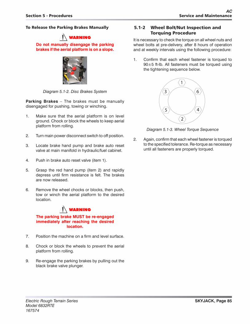
SKYJACK, Page 85Electric Rough Terrain SeriesModel 6832RTE167574
Section 5 - Procedures Service and Maintenance
To Release the Parking Brakes Manually
WARNING
Do not manually disengage the parking brakes if the aerial platform is on a slope.
Diagram 5.1-2. Disc Brakes System
Parking Brakes – The brakes must be manually disengaged for pushing, towing or winching.
1. Make sure that the aerial platform is on level ground. Chock or block the wheels to keep aerial platform from rolling.
2. Turn main power disconnect switch to off position.
3. Locate brake hand pump and brake auto reset valve at main manifold in hydraulic/fuel cabinet.
4. Push in brake auto reset valve (item 1).
5. Grasp the red hand pump (item 2) and rapidly depress until firm resistance is felt. The brakes are now released.
6. Remove the wheel chocks or blocks, then push, tow or winch the aerial platform to the desired location.
WARNING
The parking brake MUST be re-engaged immediately after reaching the desired
location.
7. Position the machine on a firm and level surface.
8. Chock or block the wheels to prevent the aerial platform from rolling.
9. Re-engage the parking brakes by pulling out the black brake valve plunger.
5.1-2 Wheel Bolt/Nut Inspection and Torquing Procedure
It is necessary to check the torque on all wheel nuts and wheel bolts at pre-delivery, after 8 hours of operation and at weekly intervals using the following procedure:
1. Confirm that each wheel fastener is torqued to 90±5 ft-Ib. All fasteners must be torqued using the tightening sequence below.
1
6
4
2
5
3
Diagram 5.1-3. Wheel Torque Sequence
2. Again, confirm that each wheel fastener is torqued to the specified tolerance. Re-torque as necessary until all fasteners are properly torqued.
AC
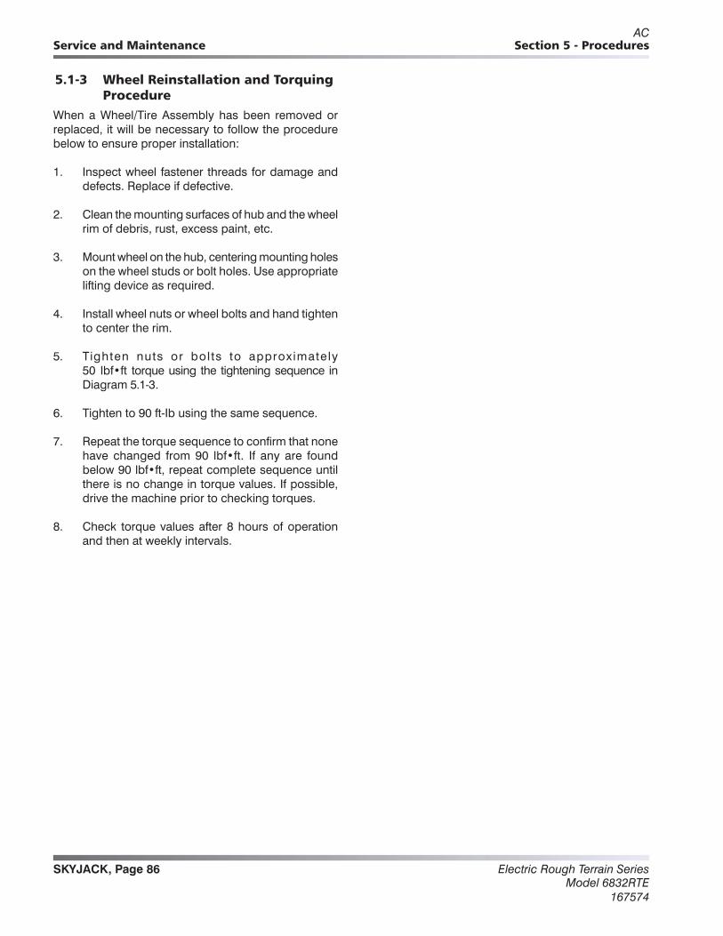
Electric Rough Terrain SeriesModel 6832RTE
167574
SKYJACK, Page 86
Section 5 - ProceduresService and Maintenance
5.1-3 Wheel Reinstallation and Torquing Procedure
When a Wheel/Tire Assembly has been removed or replaced, it will be necessary to follow the procedure below to ensure proper installation:
1. Inspect wheel fastener threads for damage and defects. Replace if defective.
2. Clean the mounting surfaces of hub and the wheel rim of debris, rust, excess paint, etc.
3. Mount wheel on the hub, centering mounting holes on the wheel studs or bolt holes. Use appropriate lifting device as required.
4. Install wheel nuts or wheel bolts and hand tighten to center the rim.
5. Tighten nuts or bol ts to approximately 50 lbf•ft torque using the tightening sequence in Diagram 5.1-3.
6. Tighten to 90 ft-Ib using the same sequence.
7. Repeat the torque sequence to confirm that none have changed from 90 lbf•ft. If any are found below 90 lbf•ft, repeat complete sequence until there is no change in torque values. If possible, drive the machine prior to checking torques.
8. Check torque values after 8 hours of operation and then at weekly intervals.
AC
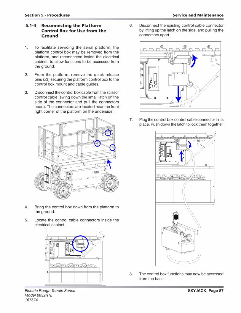
SKYJACK, Page 87Electric Rough Terrain SeriesModel 6832RTE167574
Section 5 - Procedures Service and Maintenance
5.1-4 Reconnecting the Platform Control Box for Use from the Ground
1. To facilitate servicing the aerial platform, the platform control box may be removed from the platform, and reconnected inside the electrical cabinet, to allow functions to be accessed from the ground.
2. From the platform, remove the quick release pins (x3) securing the platform control box to the control box mount and cable guides.
3. Disconnect the control box cable from the scissor control cable (swing down the small latch on the side of the connector and pull the connectors apart). The connectors are located near the front right corner of the platform on the underside.
4. Bring the control box down from the platform to the ground.
5. Locate the control cable connectors inside the electrical cabinet.
6. Disconnect the existing control cable connector by lifting up the latch on the side, and pulling the connectors apart.
7. Plug the control box control cable connector in its place. Push down the latch to lock them together.
8. The control box functions may now be accessed from the base.

Electric Rough Terrain SeriesModel 6832RTE
167574
SKYJACK, Page 88
Section 5 - ProceduresService and Maintenance
5.1-5 Tightening and Torque Recommendations for Hydraulic Couplings and Hoses
General Work Practices1. All components must be free of damage or
contamination. O-rings cannot be reused anytime the component has been installed beyond finger tight. Clean or replace components, as required.
2. Over-tightening a coupling may result in overstressing and/or cracking, and may lead to leaking or failure.
3. When tightening hose couplings, ensure the hose does not twist on the adapter. Twisting will shorten hose life and scar the sealing surfaces of swivel type couplings (JIC, 45°, etc.), which can create leaks.
4. When tightening hose couplings, use a torque wrench (with crow’s foot) on the hose end hex swivel nut, and a standard box wrench on the hose end stem hex to hold the hose from twisting.
BoxWrench
Torque Wrenchwith Crow’s Foot
5. Lubricate all o-ring surfaces with suitable hydraulic oil prior to installation in the flange head and o-ring seal grooves. This will minimize the possibility of damage to the O-ring when installed.
6. Install any 45° and 90° hydraulic hose ends first, then align direction and tighten. Adjust the swivel nut on the straight hose end before tightening to create the desired flow.
Using a Torque Wrench1. This method is applicable for JIC (37°) and
FFOR (Flat Face O-Ring) hose ends and fittings, wherever the components are accessible with torque wrench / crow’s foot tools.
2. Align the hose end or fitting to the mating component.
3. Install the nut two or three turns by hand to assure proper alignment. Jiggle the hose while tightening to ensure the faces contact fully.
4. Using a properly calibrated torque wrench, tighten the coupling using a smooth, even motion until an indication (audible click) is heard and felt. Do NOT over tighten. For recommended torque values, refer to Table 2.8 Torque Specifications for Hydraulic Couplings & Hoses.
5. Apply a drop of torque seal to the connection.
Using the Flats From Wrench Resistance Method
1. This method is applicable for JIC (37°) and FFOR (Flat Face O-Ring) hose ends only, wherever the components are inaccessible with torque wrench/crow’s foot tools, or when a properly calibrated torque wrench is not available.
2. Align the hose end or fitting to the mating component.
3. Install the swivel hose end nut hand tight to the fitting to assure proper alignment. Jiggle the hose while tightening to ensure the faces contact fully.
4. Tighten the nut using a box wrench until minor resistance is felt.
5. Note the position of the nut relative to the fitting with a marking device (i.e. paint marker).
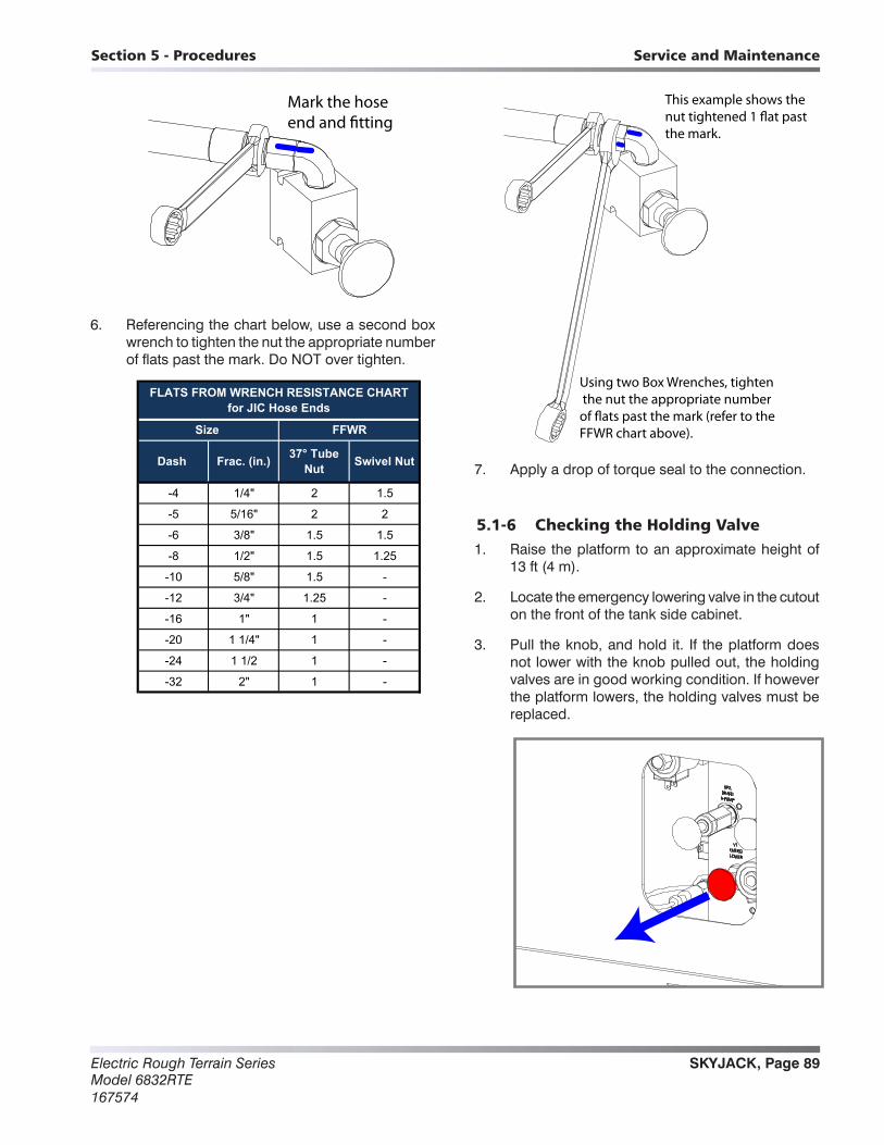
SKYJACK, Page 89Electric Rough Terrain SeriesModel 6832RTE167574
Section 5 - Procedures Service and Maintenance
Mark the hoseend and �tting
6. Referencing the chart below, use a second box wrench to tighten the nut the appropriate number of flats past the mark. Do NOT over tighten.
-4 1/4" 2 1.5
-5 5/16" 2 2
-6 3/8" 1.5 1.5
-8 1/2" 1.5 1.25
-10 5/8" 1.5 -
-12 3/4" 1.25 -
-16 1" 1 -
-20 1 1/4" 1 -
-24 1 1/2 1 -
-32 2" 1 -
FLATS FROM WRENCH RESISTANCE CHARTfor JIC Hose Ends
Size FFWR
Dash Frac. (in.) 37° Tube Nut Swivel Nut
Using two Box Wrenches, tighten the nut the appropriate numberof �ats past the mark (refer to theFFWR chart above).
This example shows thenut tightened 1 �at pastthe mark.
7. Apply a drop of torque seal to the connection.
5.1-6 Checking the Holding Valve1. Raise the platform to an approximate height of
13 ft (4 m).
2. Locate the emergency lowering valve in the cutout on the front of the tank side cabinet.
3. Pull the knob, and hold it. If the platform does not lower with the knob pulled out, the holding valves are in good working condition. If however the platform lowers, the holding valves must be replaced.

SKYJACK, Page 90Electric Rough Terrain SeriesModel 6832RTE167574
Section 5 - Procedures Service and Maintenance
5.1-7 System Pressure Setting
Checking the Pressure
1. Bring the control box down from the platform to the ground so it will be accessible while working (refer to 5.1-4).
2. Refer to the aerial platform’s serial plate for the correct system pressure for the unit.
3. Connect a pressure gauge to the quick disconnect fitting located on the lift side of the main manifold in the tank side cabinet.
Pressure gaugeattached to quickdisconnect �tting
System pressurerelief valve
4. With the engine on, use the control box joystick to steer fully left or right to produce pressure. Read the pressure on the gauge.
5. If the pressure shown on the gauge matches that on the serial plate, no further action is needed. However, if it does not match that on the serial plate, proceed to the next step.
Adjusting the Pressure
6. Continuing from step 5 above, loosen the jam nut (counterclockwise) on the system pressure relief valve.
7. Still steering fully left or right to create pressure, turn the system relief valve adjustment screw clockwise to raise the pressure, or counterclockwise the lower the pressure, until it matches the value given on the serial plate.
3. Psi should match serial plate
or
1.
2.
9. Tighten the jam nut and apply a dab of torque seal where the jam nut and adjuster screw meet.
10. Remove the pressure gauge and reconnect the control box to the platform.
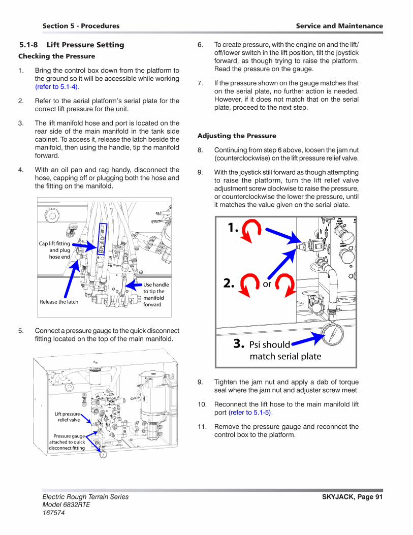
SKYJACK, Page 91Electric Rough Terrain SeriesModel 6832RTE167574
Section 5 - Procedures Service and Maintenance
5.1-8 Lift Pressure SettingChecking the Pressure
1. Bring the control box down from the platform to the ground so it will be accessible while working (refer to 5.1-4).
2. Refer to the aerial platform’s serial plate for the correct lift pressure for the unit.
3. The lift manifold hose and port is located on the rear side of the main manifold in the tank side cabinet. To access it, release the latch beside the manifold, then using the handle, tip the manifold forward.
4. With an oil pan and rag handy, disconnect the hose, capping off or plugging both the hose and the fitting on the manifold.
Release the latch
Use handleto tip themanifoldforward
Cap lift �ttingand plughose end
5. Connect a pressure gauge to the quick disconnect fitting located on the top of the main manifold.
Pressure gaugeattached to quickdisconnect �tting
Lift pressurerelief valve
6. To create pressure, with the engine on and the lift/off/lower switch in the lift position, tilt the joystick forward, as though trying to raise the platform. Read the pressure on the gauge.
7. If the pressure shown on the gauge matches that on the serial plate, no further action is needed. However, if it does not match that on the serial plate, proceed to the next step.
Adjusting the Pressure
8. Continuing from step 6 above, loosen the jam nut (counterclockwise) on the lift pressure relief valve.
9. With the joystick still forward as though attempting to raise the platform, turn the lift relief valve adjustment screw clockwise to raise the pressure, or counterclockwise the lower the pressure, until it matches the value given on the serial plate.
3. Psi should match serial plate
or
1.
2.
9. Tighten the jam nut and apply a dab of torque seal where the jam nut and adjuster screw meet.
10. Reconnect the lift hose to the main manifold lift port (refer to 5.1-5).
11. Remove the pressure gauge and reconnect the control box to the platform.

Electric Rough Terrain SeriesModel 6832RTE
167574
SKYJACK, Page 92
Section 5 - ProceduresService and Maintenance
5.1-9 Grease Points
Grease Fitting Locations
1. There are either 1 or 5 grease fittings on the 6826RTE / 6832RTE, depending on options. They are located:
• On the stationary end of the steer cylinder (1 fitting per unit).
• On each outrigger foot (1 fitting per outrigger, if equipped, 4 per unit).
Applying Grease
1. Remove the cap from the grease fitting.
2. Using a clean rag, wipe off any dirt or debris from the grease fitting.
3. Connect a grease gun to the grease fitting, and pump until a small amount of grease can be seen coming out around the joint or bearing.
4. Disconnect the grease gun.
5. Wipe off any excess grease from around the joint or bearing, and from the grease fitting.
6. Replace the grease fitting cap.

SKYJACK, Page 93Electric Rough Terrain SeriesModel 6832RTE167574
Section 5 - Procedures Service and Maintenance
5.1-10 Electronic Tilt Switch Setup Procedure
Machines that are not equipped with outriggers have an electronic tilt switch located inside the engine compartment. During operation, the switch monitors machine tilt front to back, and side to side. Aerial platform tilt is measured relative to a learned zero position.
The zero position is calibrated using the following set-up procedure, based on the position of the machine with the platform leveled and fully lowered.
Two LED indicator lights on the top of the switch show operating conditions.
Tilt Switch Replacement
Follow this procedure to install and program a new zero position in a replacement tilt switch.
NOTE: Make sure part number of old and new tilt switch are the same.
Y AXISX AXIS
1. Park aerial platform on a firm level surface.
2. Fully lower the platform.
3. Chock or block wheels to keep the aerial platform from rolling forward or backward.
4. Push in emergency stop buttons and turn main power disconnect switch off.
5. Disconnect tilt switch from 4 pin connector.
6. Remove old tilt switch from mount.
7. Install the new switch in the same orientation as the old switch. Connect switch plug to 4 pin connector.
NOTE: The tilt switch circuit is only powered when controls are powered up.
8. Turn main power disconnect switch on.
9. Select Off–Lift–Drive key switch to Lift position or Drive position.
10. Pull out all emergency stop buttons.
11. Verify switch is powered. The red and green LED indicator lights should be flashing.
12. On the back side of the switch, press and release the Set-up button 3 times.
M62332AA
13. The red LED then flashes for 4 seconds during a stabilization period.
14. Both LEDs then flash for 1 second, indicating the switch is learning the new zero position.
15. When both LEDs are on continuously, it indicates the switch has learned the new zero position.
16. The green LED then flashes and the red LED stays on for 2 seconds indicating the switch is verifying the new zero position.
LED Indicator Lights
Set-up Button

Electric Rough Terrain SeriesModel 6832RTE
167574
SKYJACK, Page 94
Section 5 - ProceduresService and Maintenance
17. The green LED stays on continuously indicating the switch is ready for normal operation.
18. Turn main power disconnect switch off.
19. Push in all emergency stop buttons.
20. Remove wheel chocks.
Reprogramming Existing Tilt Switch
Follow this procedure to reprogram an existing tilt switch. Reprogramming the switch records a new zero position.
1. Park aerial platform on a firm level surface.
2. Fully lower the platform. Reprogramming the switch learns
3. Chock or block wheels to keep the aerial platform from rolling forward or backward.
NOTE: The tilt switch circuit is only powered when controls are powered up.
4. Turn main power disconnect switch on.
5. Select Off–Lift–Drive key switch to Lift position or Drive position.
6. Pull out all emergency stop buttons.
7. Verify switch is powered. The red and green LED indicator lights should be flashing.
8. On the back side of the switch, press and hold the Set-up button for 3 seconds.
M62332AA
9. Both LEDs turn off, then begin flashing for a 5 second period.
10. During this 5 second period, press and release the Set-up button 3 times.
11. The red LED then flashes for 4 seconds during a stabilization period.
12. Both LEDs then flash for 1 second indicating the switch is learning the new zero position. When both LEDs are on continuously, it indicates the switch learned the new zero position.
13. The green LED then flashes and the red LED stays on for 2 seconds indicating the switch is verifying the new zero position.
14. The green LED stays on continuously indicating the switch is ready for normal operation.
NOTE: If the Set-up button is not pressed 3 times during Step 10, the switch exits the program mode and returns to normal operation using the previous zero point.
15. Turn main power disconnect switch off.
16. Push in all emergency stop buttons.
17. Remove wheel chocks.
LED Indicator Lights
Set-up Button
SKYJACK, Page 95Electric Rough Terrain SeriesModel 6832RTE167574
Section 5 - Procedures Service and Maintenance
Tilt Switch Operation
The following describes LED operation with the system powered.
Green LED on
The green LED on continuously indicates normal operation. Both tilt axes are within the specified degrees of the learned zero position.
The green LED flashing indicates the aerial platform is moving in or out of tilt angle limits. The time delay has not occurred yet.
Red LED on
The red LED is on continuously when the tilt angle on one or more axes is off more than the allowable degrees from the zero position.
Green and Red LEDs on
Both LEDs on continuously indicates a fault in the system is detected. The switch does not function.
After a period of 5 seconds or on power up, the switch attempts to return to normal operation. If the fault is still detected, both LEDs remain on.
Electric Rough Terrain SeriesModel 6832RTE
167574
SKYJACK, Page 96
Section 5 - ProceduresService and Maintenance
Electrical Cabinet
5.2-1 Motor Controller Panel Pin Interface
Connector B
Pin 1 - 48 volt output from line contactor to E stop switch. (Fused 10 amp) - Test between pin 1 and battery negative.
Pin 2 - 48 volt input from E stop switch to DC/DC convertor. - Test between pin 2 and battery negative.
Pin 3 - 12 volt output to CB1 circuit breaker. 12 volt input to motor controller pin A17. (Fused 10 amp)
- Test between pin 3 and battery negative.
Pin 4 - 00/ battery negative to CB2 circuit breaker. - Test for continuity between pin 4 and battery negative.
Pin 5 - 48 volt input on wire 3B to motor controller and line contactor when key on selected. - Test between pin 5 and battery negative with key on.
Pin 6 - 12 volt input on wire 13 when lower function selected. (Pump/motor not required) - Test between pin 6 and 02 wire while selecting lower function.
Pin 7 - 12 volt input on wire 44. High speed enable. (0 volts above height limit switch) - Test between pin 7 and 02 wire.
Pin 8 - Accelerator input. Signal on wire 59 from joystick controller. 0 – 5 volts. - Test between pin 8 and 02 wire.
Pin 9 - 12 volt input on wire 19. Enable switch. (Without Hybrid Power Pack running) - Test between pin 9 and 02 wire.
Pin 10 - Lift/ Drive Mode input. 2C active= Drive mode. - Test for continuity between pin 10 and battery negative while in drive mode.
Pin 11 - Base Lift input. 2A active= Base lift mode. - Test for continuity between pin 11 and battery negative while lifting from base controls.
Pin 12 - Dry Steer Mode input. 12 volt input on wire 30B. - Test between pin 12 and battery negative while activating dry steer.
Pin 13 - Platform/ Base select input. 2B active= Base mode. - Test for continuity between pin 13 and battery negative while in base mode.
Pin 14 - 12 volt input on wire 17B. Outrigger Enable signal. - Test between pin 14 and 02 wire.
AB

SKYJACK, Page 97Electric Rough Terrain SeriesModel 6832RTE167574
Section 5 - Procedures Service and Maintenance
5.2-1 Motor Controller Panel Pin Interface – Hybrid Power Pack (Gasoline)
Connector A
Pin 1 - HPP Enable. Battery negative output to wire 85. - Test for continuity between pin 1 and battery negative.
Pin 2 - HPP Auto mode. Battery negative input on wire 86. - Test for continuity between pin 2 and battery negative.
Pin 3 - HPP Manual mode. Battery negative input on wire 87. - Test for continuity between pin 3 and battery negative.
Pin 4 - HPP run proofing loop input from wire 106B. Looped through relay 106CR. - Test for continuity between pin 4 and pin 7 with HPP running.
Pin 5 - Battery negative supply to HPP start relay 10CR1 on wire 57. (Set active to 4 seconds) - Test for continuity between pin 5 and battery negative.
Pin 6 - Battery negative supply to HPP stop relay 10CR3 on wire 104. - Test for continuity between pin 6 and battery negative.
Pin 7 - HPP run proofing loop input from wire 106A. Looped through relay 106CR. - Test for continuity between pin 7 and pin 4 with HPP running.
Pin 8 - 12 volt input on wire 19B Enable switch. (With Hybrid Power Pack running) - Test between pin 9 and 02 wire.
Hybrid Power Pack Connector
Wire 106 - 12 volt output to run relay 106CR.
Wire 000 - HPP battery negative.
Wire 104A - HPP shut down when connected to wire 000. Through relay 10C3R or switch S12.
Wire 57B - 12 volt output from HPP to HPP start relay 10CR1.
Wire 57A - 12 volt output from HPP start relay 10CR1 to HPP starter.
Wire L2 - External VAC input.
Wire G1 - External VAC input.
AB

Electric Rough Terrain SeriesModel 6832RTE
167574
SKYJACK, Page 98
Section 5 - ProceduresService and Maintenance
5.2-2 ZAPI MDI CAN Display – Motor Controller Master Flash Codes
The ZAPI MDI CAN (Multi-function Digital Indicator) is connected to the motor controller via CAN-BUS. If an alarm occurs, it displays the motor controller alarm with a corresponding code. The Red LED flashes and the Wrench symbol is displayed.
When the MDI CAN is powered up, it displays general information, the software revision of the MDI display, followed by the software revision of the motor controller, and finally total machine hours. If the Turtle icon appears on power up, this indicates Creep Mode is enabled. The system goes into Creep Mode when battery charge is low.
Decoding the Alarms Displayed on the MDI-CAN
The format of the string shown on the display below is XXAYY, where XX and AYY represent the alarmed node and the alarmed code respectively.
The First two digits represent the Node of the Controller where the Alarm is present.
The Final two digits represent Alarm Code (see Table).
The Third digit represents which Sub Node the Alarm is present. This could be A or B:A – represents an Alarm on Sub Node0 – is the Master ProcessorB – represents and Alarm on Sub Node1 – is the Slave Processor
With the Controller Alarm Codes on the MDI-CAN display referenced against the Controller Master Codes Table (refer to Section 5.2-2a) and the Controller Slave Codes Table (refer to Section 5.2-2b), the operator can solve the fault and correct the error. The codes tables contain the flash codes, the probable cause and the recommended remedy. If the Alarm information suggests a serious problem that can not be addressed by the codes tables, contact Skyjack Service Department.
AD

SKYJACK, Page 99Electric Rough Terrain SeriesModel 6832RTE167574
Section 5 - Procedures Service and Maintenance
5.2-2a MDI-CAN Controller Master Codes
Flash Code Displayed on MDI Probabable Cause Remedy
05A01 WARNING SLAVE Error in slave Check slave code for fault information
05A08 WATCHDOGACE3 Controller logic selfcheck
1. Cycle keyswitch 2. Factory reset (Clear Eeprom) 3. Replace ACE3
05A10 WRONG RAM MEM.ACE3 Controller memory selfcheck
1. Cycle keyswitch 2. Factory reset (Clear Eeprom) 3. Replace ACE3
05A12 CONTROLLER MISM. Wrong software signature1. Cycle keyswitch 2. Factory reset (Clear Eeprom) 3. Replace ACE3
05A13 EEPROM KO Eeprom failure1. Cycle keyswitch 2. Factory reset (Clear Eeprom) 3. Replace ACE3
05A14 PARAM RESTORE Parameters mismatched
This warning appears when the controller restored the default values.Troubleshooting:If a CLEAR EEPROM was made before the last keyon-recycle, this warning just means that the EEPROM was correctly cleared. A travel demand or a pump request cancel's the alarm.Use the following steps if demand did not clear code:1. Cycle keyswitch2. Factory reset (Clear Eeprom)3. Replace ACE3
05A15 M/S PAR CHK MISMParameters checksum mismatch between master and slave
1. Cycle keyswitch 2. Factory reset (Clear Eeprom) 3. Replace ACE3
05A16 PARAM TRANSFERAn error occurred while transferring parameters from master to slave
1. Cycle keyswitch 2. Factory reset (Clear Eeprom) 3. Replace ACE3
05A17 LOGIC FAILURE#3ACE3 Internal check- High voltage (Overload)
1. Check battery voltage2. Factory reset (Clear Eeprom) 3. Replace ACE3
05A19 LOGIC FAILURE#1ACE3 Internal check- Low voltage
Cause:This fault is displayed when the controller detects an under voltage condition.Under voltage threshold is 16V in the 48V controller.Troubleshooting of fault displayed at startup or in standby:- Key input signal down-going pulses (below under voltage threshold) due to external loads, like DC/DC converters starting-up, relays or contactor switching, solenoids energizing / de-energizing.- If no voltage transient is detected on the supply line and the alarm is present every time the key is switched ON, the failure is probably in the controller hardware, so it is necessary to replace the ACE3.Troubleshooting of fault displayed during motor driving:- If the alarm happens during traction acceleration or driving hydraulic functions, check battery charge condition, power cable connection.
AC
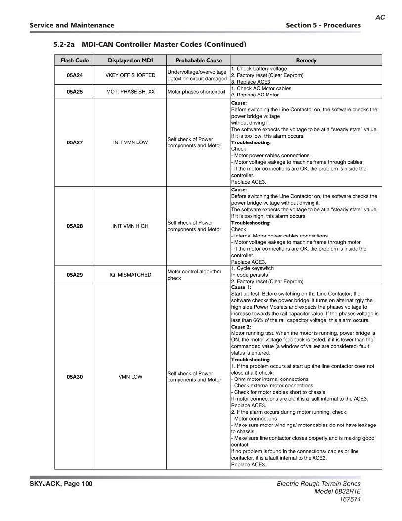
Electric Rough Terrain SeriesModel 6832RTE
167574
SKYJACK, Page 100
Section 5 - ProceduresService and Maintenance
5.2-2a MDI-CAN Controller Master Codes (Continued)
Flash Code Displayed on MDI Probabable Cause Remedy
05A24 VKEY OFF SHORTEDUndervoltage/overvoltage detection circuit damaged
1. Check battery voltage2. Factory reset (Clear Eeprom) 3. Replace ACE3
05A25 MOT. PHASE SH. XX Motor phases shortcircuit1. Check AC Motor cables2. Replace AC Motor
05A27 INIT VMN LOWSelf check of Power components and Motor
Cause:Before switching the Line Contactor on, the software checks the power bridge voltagewithout driving it.The software expects the voltage to be at a “steady state” value.If it is too low, this alarm occurs.Troubleshooting: Check- Motor power cables connections- Motor voltage leakage to machine frame through cables- If the motor connections are OK, the problem is inside the controller.Replace ACE3.
05A28 INIT VMN HIGHSelf check of Power components and Motor
Cause:Before switching the Line Contactor on, the software checks the power bridge voltage without driving it.The software expects the voltage to be at a “steady state” value. If it is too high, this alarm occurs.Troubleshooting: Check- Internal Motor power cables connections- Motor voltage leakage to machine frame through motor- If the motor connections are OK, the problem is inside the controller.Replace ACE3.
05A29 IQ MISMATCHEDMotor control algorithm check
1. Cycle keyswitchIn code persists 2. Factory reset (Clear Eeprom)
05A30 VMN LOWSelf check of Power components and Motor
Cause 1:Start up test. Before switching on the Line Contactor, the software checks the power bridge: It turns on alternatingly the high side Power Mosfets and expects the phases voltage to increase towards the rail capacitor value. If the phases voltage is less than 66% of the rail capacitor voltage, this alarm occurs.Cause 2:Motor running test. When the motor is running, power bridge is ON, the motor voltage feedback is tested; if it is lower than the commanded value (a window of values are considered) fault status is entered.Troubleshooting:1. If the problem occurs at start up (the line contactor does not close at all) check:- Ohm motor internal connections- Check external motor connections- Check for motor cables short to chassisIf motor connections are ok, it is a fault internal to the ACE3. Replace ACE3.2. If the alarm occurs during motor running, check:- Motor connections- Make sure motor windings/ motor cables do not have leakage to chassis- Make sure line contactor closes properly and is making good contact.If no problem is found in the connections/ cables or line contactor, it is a fault internal to the ACE3.Replace ACE3.
AC
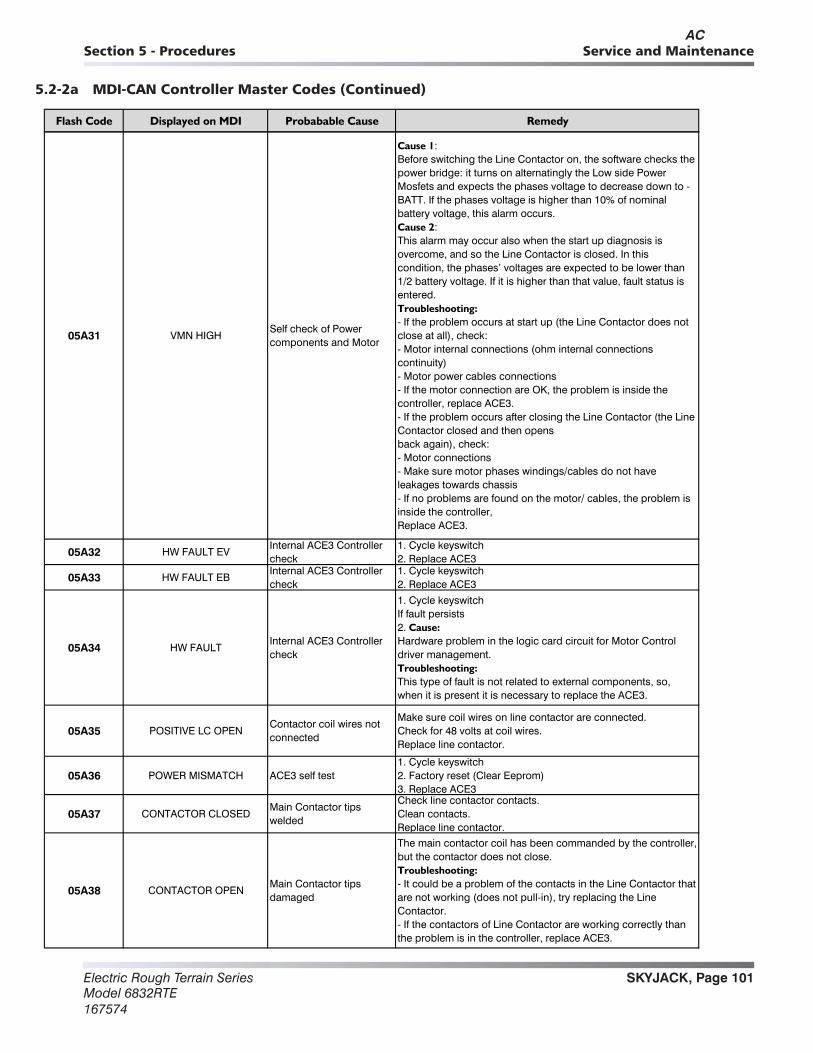
SKYJACK, Page 101Electric Rough Terrain SeriesModel 6832RTE167574
Section 5 - Procedures Service and Maintenance
5.2-2a MDI-CAN Controller Master Codes (Continued)
Flash Code Displayed on MDI Probabable Cause Remedy
05A31 VMN HIGHSelf check of Power components and Motor
Cause 1:Before switching the Line Contactor on, the software checks the power bridge: it turns on alternatingly the Low side Power Mosfets and expects the phases voltage to decrease down to -BATT. If the phases voltage is higher than 10% of nominal battery voltage, this alarm occurs.Cause 2:This alarm may occur also when the start up diagnosis is overcome, and so the Line Contactor is closed. In this condition, the phases’ voltages are expected to be lower than 1/2 battery voltage. If it is higher than that value, fault status is entered.Troubleshooting:- If the problem occurs at start up (the Line Contactor does not close at all), check:- Motor internal connections (ohm internal connections continuity)- Motor power cables connections- If the motor connection are OK, the problem is inside the controller, replace ACE3.- If the problem occurs after closing the Line Contactor (the Line Contactor closed and then opensback again), check:- Motor connections- Make sure motor phases windings/cables do not have leakages towards chassis- If no problems are found on the motor/ cables, the problem is inside the controller,Replace ACE3.
05A32 HW FAULT EVInternal ACE3 Controller check
1. Cycle keyswitch 2. Replace ACE3
05A33 HW FAULT EBInternal ACE3 Controller check
1. Cycle keyswitch 2. Replace ACE3
05A34 HW FAULTInternal ACE3 Controller check
1. Cycle keyswitchIf fault persists2. Cause:Hardware problem in the logic card circuit for Motor Control driver management.Troubleshooting:This type of fault is not related to external components, so, when it is present it is necessary to replace the ACE3.
05A35 POSITIVE LC OPENContactor coil wires not connected
Make sure coil wires on line contactor are connected.Check for 48 volts at coil wires.Replace line contactor.
05A36 POWER MISMATCH ACE3 self test1. Cycle keyswitch 2. Factory reset (Clear Eeprom) 3. Replace ACE3
05A37 CONTACTOR CLOSEDMain Contactor tips welded
Check line contactor contacts.Clean contacts.Replace line contactor.
05A38 CONTACTOR OPENMain Contactor tips damaged
The main contactor coil has been commanded by the controller, but the contactor does not close.Troubleshooting:- It could be a problem of the contacts in the Line Contactor that are not working (does not pull-in), try replacing the Line Contactor.- If the contactors of Line Contactor are working correctly than the problem is in the controller, replace ACE3.
AC

Electric Rough Terrain SeriesModel 6832RTE
167574
SKYJACK, Page 102
Section 5 - ProceduresService and Maintenance
5.2-2a MDI-CAN Controller Master Codes (Continued)
Flash Code Displayed on MDI Probabable Cause Remedy
05A39 FIELD ORIENT. KO ACE3 Motor algorithm test1. Cycle keyswitch 2. Factory reset (Clear Eeprom) 3. Replace ACE3
05A40 EB. DRIV.SHRT.The hybrid relay driver is shorted.
1. Cycle keyswitch 2. Factory reset (Clear Eeprom) 3. Replace ACE3
05A41 WRONG SET BAT.ACE3 rejects the battery voltage reading
At start-up, the controller checks the battery voltage and verify it is within a window around the nominal value.Troubleshooting:- Check that the controller SET BATTERY parameter value matches the battery nominal voltage.- Check that TESTER MENU / BATTERY VOLTAGE parameter shows same value as the battery voltage measured with a voltmeter. If it does not match, then do an “ADJUST BATTERY” function.
05A42 EB. DRIV.OPENThe hybrid relay driver is not able to close.
Refer to Hybrid Power Pack troubleshooting in Section 4.
05A43 EB. COIL OPENHybrid coil is not connected.
Refer to Hybrid Power Pack troubleshooting in Section 4.
05A44 COIL SHOR. EVAUX Relay coil is shorted Refer to Hybrid Power Pack troubleshooting in Section 4.
05A45 DRV. SHOR. EVInternal ACE3 Controller check
1. Cycle keyswitch 2. Factory reset (Clear Eeprom) 3. Replace ACE3
05A46 CONT. DRV. EVInternal ACE3 Controller check
1. Cycle keyswitch 2. Factory reset (Clear Eeprom) 3. Replace ACE3
05A50 LC COIL OPEN Contactor coil testMake sure coil wires on line contactor are connected correctly.Replace line contactor.
05A51 TILLER OPENNo operator input, machine in standby
Warning when the joystick is released, after a fixed period of time of standby (30 seconds) the main contactor opens.Troubleshooting:At the next function request the warning will disappear.
05A53 STBY I HIGHInternal ACE3 Controller check
1. Cycle keyswitch (If code remains see next)Cause:The current transducer or the current feedback circuit is damaged in the Controller Troubleshooting:This type of fault is not related to external components so, when it is present, it is necessary to replace the ACE3.
05A55 OPEN COIL EV. XX EVxx coil is not connectedCheck wiring to relays from ACE3 Pins A18, B16.Refer to Hybrid Power Pack Troubleshooting in Section 4.
05A56 THROTTLE PROG. Wrong Joystick profile 1. Factory reset (Clear Eeprom)
05A60 CAPACITOR CHARGE Startup test1. Check battery voltage2. Check battery and motor cables
05A61 THERMIC SENS. KO ACE3 Controller
Cause:The output of the controller thermal sensor is out of range.Troubleshooting:This type of fault is not related to external components; replace the ACE3.
AC
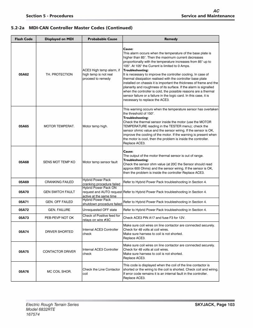
SKYJACK, Page 103Electric Rough Terrain SeriesModel 6832RTE167574
Section 5 - Procedures Service and Maintenance
5.2-2a MDI-CAN Controller Master Codes (Continued)
Flash Code Displayed on MDI Probabable Cause Remedy
05A62 TH. PROTECTIONACE3 High temp alarm, if high temp is not real proceed to remedy
Cause:This alarm occurs when the temperature of the base plate is higher than 85°. Then the maximum current decreases proportionally with the temperature increases from 85° up to 105°. At 105° the Current is limited to 0 Amps.Troubleshooting:It is necessary to improve the controller cooling. In case of thermal dissipation realised with the controller base plate installed on chassis it is important the thickness of frame and the planarity and roughness of its surface. If the alarm is signalled when the controller is cold, the possible reasons are a thermal sensor failure or a failure in the logic card. In this case, it is necessary to replace the ACE3.
05A65 MOTOR TEMPERAT. Motor temp high.
This warning occurs when the temperature sensor has overtaken the threshold of 150°. Troubleshooting:Check the thermal sensor inside the motor (use the MOTOR TEMPERATURE reading in the TESTER menu); check the sensor ohmic value and the sensor wiring. If the sensor is OK, improve the cooling of the motor. If the warning is present when the motor is cool, then the problem is inside the controller. Replace ACE3.
05A68 SENS MOT TEMP KO Motor temp sensor fault
Cause: The output of the motor thermal sensor is out of range.Troubleshooting:Check the sensor ohm value (at 20C the Sensor should read approx 600 Ohms) and the sensor wiring. If the sensor is OK, then the problem is inside the controller Replace ACE3.
05A69 CRANKING FAILEDHybrid Power Pack cranking procedure failed
Refer to Hybrid Power Pack troubleshooting in Section 4.
05A70 GEN SWITCH FAULTHybrid Power Pack ON request and AUTO request active at the same time
Refer to Hybrid Power Pack troubleshooting in Section 4.
05A71 GEN. OFF FAILEDHybrid Power Pack shutdown procedure failed
Refer to Hybrid Power Pack troubleshooting in Section 4.
05A72 GEN. FAILURE Unrequested OFF state Refer to Hybrid Power Pack troubleshooting in Section 4.
05A73 PEB-PEVP NOT OKCheck of Positive feed for relays on wire #3C
Check ACE3 PIN A17 and fuse F3 for 12V.
05A74 DRIVER SHORTEDInternal ACE3 Controller check
Make sure coil wires on line contactor are connected securely.Check for 48 volts at coil wires.Make sure harness to coil is not shorted.Replace ACE3.
05A75 CONTACTOR DRIVERInternal ACE3 Controller check
Make sure coil wires on line contactor are connected securely.Check for 48 volts at coil wires.Make sure harness to coil is not shorted.Replace ACE3.
05A76 MC COIL SHOR.Check the Line Contactor coil
This code is displayed when the coil of the line contactor is shorted or the wiring to the coil is shorted. Check coil and wiring. If error code remains it is an internal fault in the controller. Replace ACE3.
AC
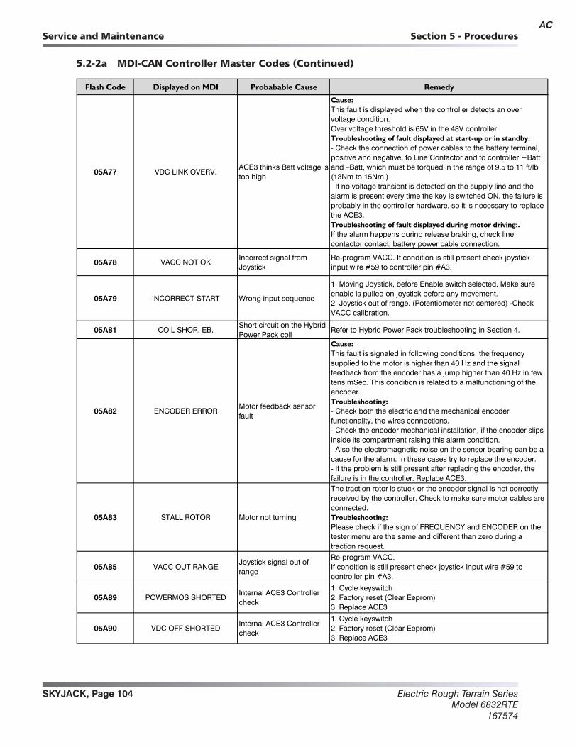
Electric Rough Terrain SeriesModel 6832RTE
167574
SKYJACK, Page 104
Section 5 - ProceduresService and Maintenance
5.2-2a MDI-CAN Controller Master Codes (Continued)
Flash Code Displayed on MDI Probabable Cause Remedy
05A77 VDC LINK OVERV.ACE3 thinks Batt voltage is too high
Cause:This fault is displayed when the controller detects an over voltage condition.Over voltage threshold is 65V in the 48V controller.Troubleshooting of fault displayed at start-up or in standby:- Check the connection of power cables to the battery terminal, positive and negative, to Line Contactor and to controller +Batt and –Batt, which must be torqued in the range of 9.5 to 11 ft/lb (13Nm to 15Nm.)- If no voltage transient is detected on the supply line and the alarm is present every time the key is switched ON, the failure is probably in the controller hardware, so it is necessary to replace the ACE3.Troubleshooting of fault displayed during motor driving:.If the alarm happens during release braking, check line contactor contact, battery power cable connection.
05A78 VACC NOT OKIncorrect signal from Joystick
Re-program VACC. If condition is still present check joystick input wire #59 to controller pin #A3.
05A79 INCORRECT START Wrong input sequence
1. Moving Joystick, before Enable switch selected. Make sure enable is pulled on joystick before any movement.2. Joystick out of range. (Potentiometer not centered) -Check VACC calibration.
05A81 COIL SHOR. EB.Short circuit on the Hybrid Power Pack coil
Refer to Hybrid Power Pack troubleshooting in Section 4.
05A82 ENCODER ERRORMotor feedback sensor fault
Cause:This fault is signaled in following conditions: the frequency supplied to the motor is higher than 40 Hz and the signal feedback from the encoder has a jump higher than 40 Hz in few tens mSec. This condition is related to a malfunctioning of the encoder.Troubleshooting:- Check both the electric and the mechanical encoder functionality, the wires connections.- Check the encoder mechanical installation, if the encoder slips inside its compartment raising this alarm condition.- Also the electromagnetic noise on the sensor bearing can be a cause for the alarm. In these cases try to replace the encoder.- If the problem is still present after replacing the encoder, the failure is in the controller. Replace ACE3.
05A83 STALL ROTOR Motor not turning
The traction rotor is stuck or the encoder signal is not correctly received by the controller. Check to make sure motor cables are connected.Troubleshooting:Please check if the sign of FREQUENCY and ENCODER on the tester menu are the same and different than zero during a traction request.
05A85 VACC OUT RANGEJoystick signal out of range
Re-program VACC.If condition is still present check joystick input wire #59 to controller pin #A3.
05A89 POWERMOS SHORTEDInternal ACE3 Controller check
1. Cycle keyswitch 2. Factory reset (Clear Eeprom) 3. Replace ACE3
05A90 VDC OFF SHORTEDInternal ACE3 Controller check
1. Cycle keyswitch 2. Factory reset (Clear Eeprom) 3. Replace ACE3
AC

SKYJACK, Page 105Electric Rough Terrain SeriesModel 6832RTE167574
Section 5 - Procedures Service and Maintenance
5.2-2a MDI-CAN Controller Master Codes (Continued)
Flash Code Displayed on MD ydemeResuaC elbababorPI
05A91 PEV NOT OKTest on positive supply to relays
Check Pin #B1 for 12 volts at controller.
05A92
05A94
CURRENT GAINInternal ACE3 Controller check
1. Cycle keyswitch 2. Factory reset (Clear Eeprom) 3. Replace ACE3
05A96 ANALOG INPUT Analog to digital failure
Cause:This alarm occurs when the A/D conversion of the analog inputs gives frozen value, on all of the converted signals, for more than 400msec. The goal of this diagnosis is to detect a failure of the A/D converter or a problem in the code flow that omits the refreshing of the analog signal conversion.Troubleshooting:If the problem occurs permanently it is necessary to Replace ACE3.
05A97 WRONG SLAVE VER.Wrong slave software version
Factory reset, (Clear Eeprom)
05A98
16A06
TORQUE PROFILE Wrong settings
NO COMMUNICATION
1. Cycle keyswitch 2. Factory reset (Clear Eeprom) 3. Replace ACE3
Hour difference betwen controller and MDI is greater than 10 hours
It stops the machine for 2 minutes, then the MDI is updated with controller hours.
Communication problem with Traction Controller.
1. Check the connections between MDI-CAN and controller.2. Replace MDI.
AD

Electric Rough Terrain SeriesModel 6832RTE
167574
SKYJACK, Page 106
Section 5 - ProceduresService and Maintenance
5.2-2b MDI-CAN Controller Slave Codes
Flash Code Displayed on MDI Probabable Cause Remedy
05B08 WATCHDOGACE3 Controller logic selfcheck
1. Cycle keyswitch 2. Factory reset (Clear Eeprom) 3. Replace ACE3
05B10 WRONG RAM MEM.ACE3 Controller memeory selfcheck
1. Cycle keyswitch 2. Factory reset (Clear Eeprom) 3. Replace ACE3
05B12 CONTROLLER MISM. Wrong software signature1. Cycle keyswitch 2. Factory reset (Clear Eeprom) 3. Replace ACE3
05B13 EEPROM KO Eeprom failure1. Cycle keyswitch 2. Factory reset (Clear Eeprom) 3. Replace ACE3
05B14 PARAM RESTORE Parameters mismatched
This warning appears when the controller restored the default values.Troubleshooting:If a CLEAR EEPROM was made before the last keyon-recycle, this warning just means that the EEPROM was correctly cleared. A travel demand or a pump request cancel's the alarm.Use the following steps if demand did not clear code:1. Cycle keyswitch2. Factory reset (Clear Eeprom)3. Replace ACE3
05B19 LOGIC FAILURE#1ACE3 Internal check- Low voltage
Cause:This fault is displayed when the controller detects an under voltage condition.Under voltage threshold is 16V in the 48V controller.Troubleshooting of fault displayed at startup or in standby:- Key input signal down-going pulses (below under voltage threshold) due to external loads, like DC/DC converters starting-up, relays or contactor switching, solenoids energizing / de-energizing.- If no voltage transient is detected on the supply line and the alarm is present every time the key is switched ON, the failure is probably in the controller hardware, so it is necessary to replace the ACE3.Troubleshooting of fault displayed during motor driving:- If the alarm happens during traction acceleration or driving hydraulic functions, check battery charge condition, power cable connection.
05B20 OUT MISMATCH XX ACE3 Internal check
This is a safety related test. Slave μC has detected that the Master μC is driving traction motor in a wrong way (not correspondant to the status of operator commands).1. Cycle keyswitch 2. Factory reset (Clear Eeprom) 3. Replace ACE3
05B21 SP MISMATCH XX ACE3 Internal check
This is a safety related test. The Master μC has detected a Slave μC wrong setpoint.1. Cycle keyswitch 2. Factory reset (Clear Eeprom) 3. Replace ACE3
05B22 INPUT MISMATCH ACE3 Internal check1. Cycle keyswitch 2. Factory reset (Clear Eeprom) 3. Replace ACE3
AC

SKYJACK, Page 107Electric Rough Terrain SeriesModel 6832RTE167574
Section 5 - Procedures Service and Maintenance
5.2-2a MDI-CAN Controller Slave Codes (Continued)
Flash Code Displayed on MDI Probabable Cause Remedy
05B23 W.SET. TG-EB XXWrong MC/EB setpoint detected
1. Cycle keyswitch 2. Factory reset (Clear Eeprom) 3. Replace ACE3
05B67 NO CAN MSG. ACE3 Internal check1. Cycle keyswitch 2. Factory reset (Clear Eeprom) 3. Replace ACE3
05B77 VDC LINK OVERV.ACE3 thinks Batt voltage is too high
Cause:This fault is displayed when the controller detects an over voltage condition.Over voltage threshold is 65V in the 48V controller.Troubleshooting of fault displayed at start-up or in standby:- Check the connection of power cables to the battery terminal, positive and negative, to Line Contactor and to controller +Batt and –Batt, which must be torqued in the range of 9.5 to 11 ft/lb (13Nm to 15Nm.)- If no voltage transient is detected on the supply line and the alarm is present every time the key is switched ON, the failure is probably in the controller hardware, so it is necessary to replace the ACE3.Troubleshooting of fault displayed during motor driving:If the alarm happens during release braking, check line contactor contact, battery power cable connection.
05B96 ANALOG INPUT Analog to digital failure
Cause:This alarm occurs when the A/D conversion of the analog inputs gives frozen value, on all of the converted signals, for more than 400msec. The goal of this diagnosis is to detect a failure of the A/D converter or a problem in the code flow that omits the refreshing of the analog signal conversion.Troubleshooting:If the problem occurs permanently it is necessary to Replace ACE3.
05B99 CTRAP THRESHOLD
This fault is displayed when the controller detects a wrong value in the feedback for overcurrent protection circuit.
1. Cycle keyswitch 2. Factory reset (Clear Eeprom) 3. Replace ACE3
AC
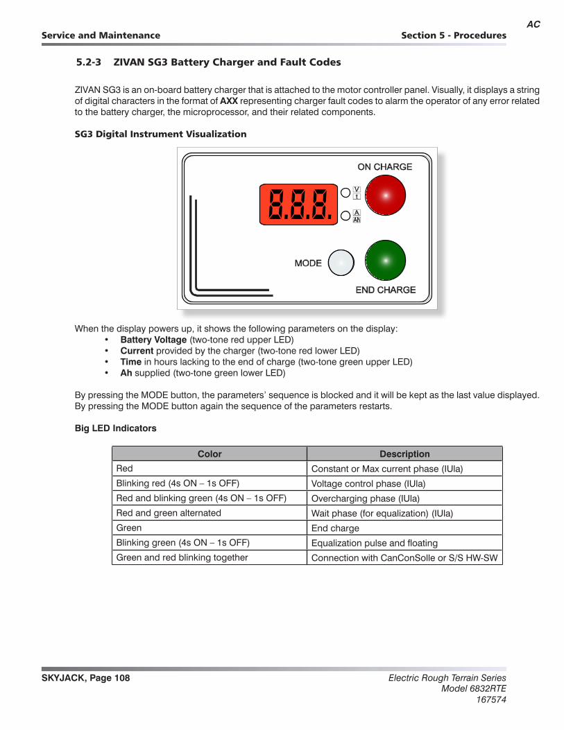
Electric Rough Terrain SeriesModel 6832RTE
167574
SKYJACK, Page 108
Section 5 - ProceduresService and Maintenance
5.2-3 ZIVAN SG3 Battery Charger and Fault Codes
ZIVAN SG3 is an on-board battery charger that is attached to the motor controller panel. Visually, it displays a string of digital characters in the format of AXX representing charger fault codes to alarm the operator of any error related to the battery charger, the microprocessor, and their related components.
SG3 Digital Instrument Visualization
When the display powers up, it shows the following parameters on the display:• Battery Voltage (two-tone red upper LED)• Current provided by the charger (two-tone red lower LED)• Time in hours lacking to the end of charge (two-tone green upper LED)• Ah supplied (two-tone green lower LED)
By pressing the MODE button, the parameters’ sequence is blocked and it will be kept as the last value displayed. By pressing the MODE button again the sequence of the parameters restarts.
Big LED Indicators
Color Description
Red Constant or Max current phase (IUla)
Blinking red (4s ON – 1s OFF) Voltage control phase (IUla)
Red and blinking green (4s ON – 1s OFF) Overcharging phase (IUla)
Red and green alternated Wait phase (for equalization) (IUla)
Green End charge
Blinking green (4s ON – 1s OFF) Equalization pulse and floating
Green and red blinking together Connection with CanConSolle or S/S HW-SW
AC
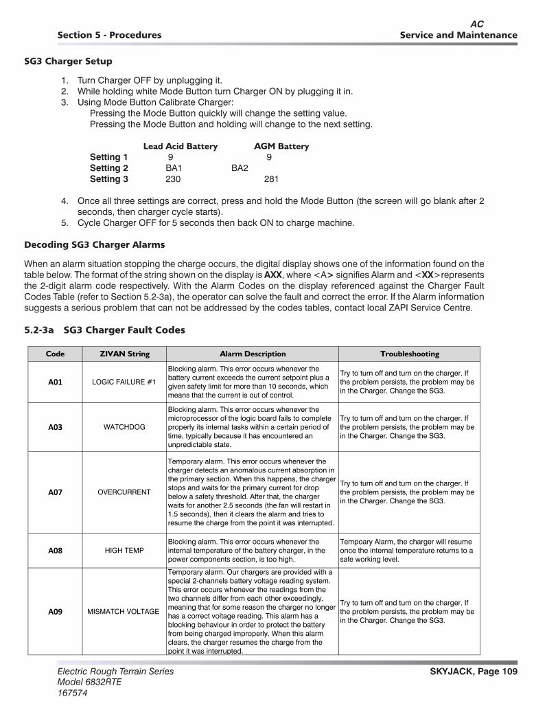
SKYJACK, Page 109Electric Rough Terrain SeriesModel 6832RTE167574
Section 5 - Procedures Service and Maintenance
SG3 Charger Setup
1. Turn Charger OFF by unplugging it.2. While holding white Mode Button turn Charger ON by plugging it in.3. Using Mode Button Calibrate Charger:
Pressing the Mode Button quickly will change the setting value.Pressing the Mode Button and holding will change to the next setting.
Lead Acid Battery AGM BatterySetting 1 9 9Setting 2 BA1 BA2Setting 3 230 281
4. Once all three settings are correct, press and hold the Mode Button (the screen will go blank after 2 seconds, then charger cycle starts).
5. Cycle Charger OFF for 5 seconds then back ON to charge machine.
Decoding SG3 Charger Alarms
When an alarm situation stopping the charge occurs, the digital display shows one of the information found on the table below. The format of the string shown on the display is AXX, where <A> signifies Alarm and <XX>represents the 2-digit alarm code respectively. With the Alarm Codes on the display referenced against the Charger Fault Codes Table (refer to Section 5.2-3a), the operator can solve the fault and correct the error. If the Alarm information suggests a serious problem that can not be addressed by the codes tables, contact local ZAPI Service Centre.
5.2-3a SG3 Charger Fault Codes
Code ZIVAN String Alarm Description Troubleshooting
A01 LOGIC FAILURE #1
Blocking alarm. This error occurs whenever the battery current exceeds the current setpoint plus a given safety limit for more than 10 seconds, which means that the current is out of control.
Try to turn off and turn on the charger. If the problem persists, the problem may be in the Charger. Change the SG3.
A03 WATCHDOG
Blocking alarm. This error occurs whenever the microprocessor of the logic board fails to complete properly its internal tasks within a certain period of time, typically because it has encountered an unpredictable state.
Try to turn off and turn on the charger. If the problem persists, the problem may be in the Charger. Change the SG3.
A07 OVERCURRENT
Temporary alarm. This error occurs whenever the charger detects an anomalous current absorption in the primary section. When this happens, the charger stops and waits for the primary current for drop below a safety threshold. After that, the charger waits for another 2.5 seconds (the fan will restart in 1.5 seconds), then it clears the alarm and tries to resume the charge from the point it was interrupted.
Try to turn off and turn on the charger. If the problem persists, the problem may be in the Charger. Change the SG3.
A08 HIGH TEMPBlocking alarm. This error occurs whenever the internal temperature of the battery charger, in the power components section, is too high.
Tempoary Alarm, the charger will resume once the internal temperature returns to a safe working level.
A09 MISMATCH VOLTAGE
Temporary alarm. Our chargers are provided with a special 2-channels battery voltage reading system. This error occurs whenever the readings from the two channels differ from each other exceedingly, meaning that for some reason the charger no longer has a correct voltage reading. This alarm has a blocking behaviour in order to protect the battery from being charged improperly. When this alarm clears, the charger resumes the charge from the point it was interrupted.
Try to turn off and turn on the charger. If the problem persists, the problem may be in the Charger. Change the SG3.
AC

Electric Rough Terrain SeriesModel 6832RTE
167574
SKYJACK, Page 110
Section 5 - ProceduresService and Maintenance
5.2-3a SG3 Charger Fault Codes (Continued)
Code ZIVAN String Alarm Description Troubleshooting
A10 TIMEOUT
Blocking alarm. This error occurs when the charger reaches the phase 1 timeout. This time is calculated as the total charging time (which in its turn depends on the programmed capacity).
Check SG3 is correctly programmed for the battery which is connected. Turn off and On the charger to see if the problem clears. If the problem remains, check the specific gravity of each battery cell. Replace SG3.
A16 LOGIC FAILIURE #2
Temporary alarm. This error reports a problem in the voltage levels of the power supply, which is typically caused by a hole in the mains voltage. During this alarm the charger stops and, similarly to the A07 alarm, waits for 2.5 seconds and then tries to resume the charge from the point it was interrupted.
Wait for the charger to try the restarting procedure. If the problem persists, check that the input power cord is properly working and make sure that the mains voltage is correct.
A17 FLASH CHECKSUM
Blocking alarm. This error occurs when the microprocessor detects a corruption in its internal flash memory. This is done through a checksum algorithm that is able to understand (with some limitations) if the microprocessor is running the same exact program that was originally programmed or not.
Try to turn off and turn on the charger. If the problem persists, the problem may be in the Charger. Change the SG3.
A18 EEPROM CHECKSUM
Blocking alarm. This error occurs whenever there microprocessor detects communications problem with the external EEPROM memory. When this alarm is shown in ZnCanConsole, it is also followed by a number or an acronym that is used by Zivan to understand how the alarm was generated.
Try to turn off and turn on the charger. If the problem persists, the problem may be in the Charger. Change the SG3
A23 POWER FAIL #1Output Current Sensing Circuit not functioning correctly
Try to turn off and turn on the charger. If the problem persists, the problem may be in the Charger. Change the SG3.
A24 WRONG MAINS INPUTThe mains input voltage is outside of the allowable working range
Check Mains input voltage.
A25 SHORT OUTPUT
Blocking alarm. This alarm occurs when the charger detects a significant current and a low voltage (< 1.05 V/cell) for 10 consecutive seconds. In this case the charger stops.
The output of the charger has probably a short circuit. Check for short circuits in the connection cable and make sure that the connectors are not in touch with metallic parts. If the problem persists, the charger may be damaged. Change the SG3.
A26 WRONG MARKER EEP Flash memory corruptedTry to turn off and turn on the charger. If the problem persists, the problem may be in the Charger. Change the SG3.
A27 NO MAINS Mains input to the charger is not correct Check Mains input voltage.
A28 LOW TEMP Chargers internal temperature is below -30CTempoary Alarm, the charger will resume once the internal temperature returns to a safe working level.
A29 CLOCK BATTERY OFF
Non- blocking alarm. This error occurs whenever the Year indication of the Clock Calendar is zero. This happens when the button cell battery in the logic board is discharged or removed, or there are communications problem between the microprocessor and the Clock Calendar. The control algorithm or this alarm is performed only once at the turn on of the charger. If the display is present, this alarm will be shown in the data roll, after the charged amperehours (or eventually the number of slave devices, if there are any). The battery supplied with the charger has an expected service life of 5 years.
Internal battery needs to be replaced, contact local Zapi Service Centre.
AC
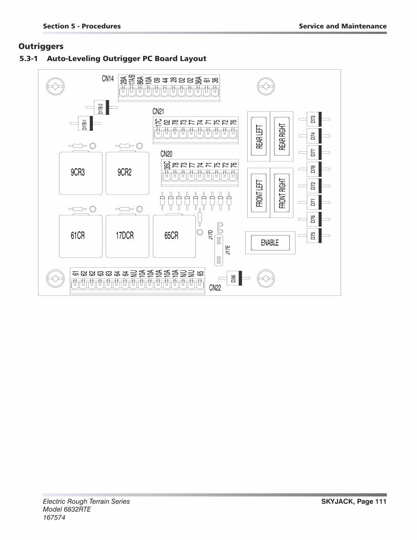
SKYJACK, Page 111Electric Rough Terrain SeriesModel 6832RTE167574
Section 5 - Procedures Service and Maintenance
Outriggers5.3-1 Auto-Leveling Outrigger PC Board Layout
36614486A28A
17A/B
10A 09 0228 02 36ACN14
0217C 7675717778 73 74 72
CN21D17B
-2
D17B
-1
REAR
LEFT
REAR
RIGH
T D73
D75
D76
D71
D72
D78
D77
D74
FRON
T RIGH
T
FRON
T LEF
T
ENABLE
CN22
D36
65CR17DCR
9CR2
CN20
35C 72747378 77 71 75 76
10A6261 636362 64 64 N/U N/UN/U10A
10A
10A
10A 65
61CR
9CR3
J17E
J17D

Electric Rough Terrain SeriesModel 6832RTE
167574
SKYJACK, Page 112
Section 5 - ProceduresService and Maintenance
5.3-2 Outrigger Mechanical Limit Switch Wiring Diagram
O.R. UP SWITCH (NO) - BLUE & BROWN
BACK VIEW - MALE
O.R. UP SWITCH (NO) - BLUE & BROWN
O.R. UP SWITCH (NO) - BLUE & BROWN
O.R. DOWN SWITCH (NC) - BLACK & BLACK / WHITE
1
23
4
1
2 3
4
PIN 1 - BLACKPIN 2 - BLACK / WHITEPIN 3 - BLUEPIN 4 - BROWN
BACK VIEW - MALE
1
23
4
PIN 1 - BLACKPIN 2 - BLACK / WHITEPIN 3 - BLUEPIN 4 - BROWN
BACK VIEW - MALE
1
23
4
PIN 1 - BLACKPIN 2 - BLACK / WHITEPIN 3 - BLUEPIN 4 - BROWN
BACK VIEW - MALE
1
23
4
PIN 1 - BLACKPIN 2 - BLACK / WHITEPIN 3 - BLUEPIN 4 - BROWN
BACK VIEW - FEMALE
1
2 3
4
BACK VIEW - FEMALE
LEFT FRONT OUTRIGGER
1
2 3
4
BACK VIEW - FEMALELEFT REAR OUTRIGGER
RIGHT FRONT OUTRIGGER
1
2 3
4
BACK VIEW - FEMALE
RIGHT REAR OUTRIGGER
O.R. DOWN SWITCH (NC) - BLACK & BLACK / WHITE
O.R. UP SWITCH (NO) - BLUE & BROWN
LEFT FRONT OUTRIGGER SECTION VIEW(SHOWN IN THE RETRACTED STATE)
RIGHT FRONT OUTRIGGER SECTION VIEW(SHOWN IN THE RETRACTED STATE)
O.R. DOWN SWITCH (NC) - BLACK & BLACK / WHITEO.R. DOWN SWITCH (NC) - BLACK & BLACK / WHITE
LEFT REAR OUTRIGGER SECTION VIEW(SHOWN IN THE RETRACTED STATE)
RIGHT REAR OUTRIGGER SECTION VIEW(SHOWN IN THE RETRACTED STATE)
SIXTEEN PIN CONNECTOR PLUG OUTRIGGER PCB ON ELECTRICAL PANEL
TO CONTROL MODULEPIN 1 - 65 GREEN / BLACKPIN 2 - 65A WHITEPIN 3 - 66A WHITEPIN 4 - 67A WHITEPIN 5 - 68A WHITEPIN 6 - (N/U)
LEFT REAR
RIGHT REAR
RIGHT FRONT
LEFT FRONT
PIN 1 - 61 PIN 2 - 62 GREENPIN 3 - 62 REDPIN 4 - 63 GREENPIN 5 - 63 REDPIN 6 - 64 GREENPIN 7 - 64 REDPIN 8 - N/U
PIN 9 - 10A BLACK (2x)PIN 10 - 10A BLACK (2x)PIN 11 - 10A BLACK (2x)PIN 12 - 10A BLACK (2x)PIN 13 - 10A GREENPIN 14 - N/UPIN 15 - N/UPIN 16 - 65 GREEN/BLACK
PIN 2 - WHITE (65A)
PIN 4 - RED (36)
PIN 1 - BLACK (10A)
PIN 3 - GREEN (62)
PIN 1 - BLACK (10A)
PIN 3 - GREEN (63)PIN 2 - WHITE (66A)
PIN 4 - RED (62)
PIN 1 - BLACK (10A)
PIN 3 - GREEN (64)PIN 2 - WHITE (67A)
PIN 4 - RED (63)PIN 1 - BLACK (10A)
PIN 3 - GREEN (10A)PIN 2 - WHITE (68A)
PIN 4 - RED (64)

SKYJACK, Page 113Electric Rough Terrain SeriesModel 6832RTE167574
Section 5 - Procedures Service and Maintenance
5.2-3 Auto-Leveling Outrigger Settings and Error Codes
Reading the Codes:
In order to read the fault codes, a sequence of pauses and flashes can be seen on the LED mounted on the outrig-ger control module. The codes are continuously displayed by the LED until the fault is cleared, the outrigger control module is reset and no longer detects the fault, or idle timeout becomes active.The sequence is as follows:
1. Half second flashes followed by half second pauses indicate the first digit.2. A 2.5 second pause.3. Half second flashes followed by half second pauses indicate the second digit4. A 5 second pause.
Repeat steps 1–4
Since the outrigger control module only reports one error, only one code can be read from the LED per instance. If the error is cleared and another error is present, it will then be presented.
LED ERROR CODES
EVERYTHING OK ON
VEHICLE TILTED 1/1
OUTRIGGERS CANNOT BE MOVED ! 1/2
OUTRIGGERS NOT HOME 2/2
NOT FULLY LEVEL 2/1
RELEASE OUTRIGGER DEMAND ! 5/5
CHECK OUTRIGGER SUPPLY (P4-9) 5/2
CANNOT LEVEL : BAD TILT SENSOR 7/1
OUTRIGGERS MANUALLY CONTROLLED ! 6/6
TESTING HWFS 7/8
B+ SUPPLY TOO LOW 5/1
STARTUP ! 7/7
FAULT : BAD SLAVE MICRO 7/5
FAULT : BAD TILT SENSOR 7/1
FAULT : BAD HWFS 7/2
FAULT : P2-5 FAULTY 8/1
FAULT : P2-6 FAULTY 8/2
FAULT : P2-8 STUCK ON 8/3
FAULT : P2-8 ALWAYS ON 8/4
FAULT : P2-8 ALWAYS OFF 8/5
FAULT : HWFS STALLED ! 7/6
60402AA

Electric Rough Terrain SeriesModel 6832RTE
167574
SKYJACK, Page 114
Section 5 - ProceduresService and Maintenance
5.3-4 Auto-Leveling Outrigger Error Code Breakdown
RELEASE OUTRIGGER DEMAND! 5/5 Check inputs on P2 pins 5 & 6 - the “auto-level” or “auto-retract” input is active at power-on or when it is not allowed to carry out the function.
OUTRIGGERS CANNOT BE MOVED! 1/2 Check input on P2 pin 10 – “auto-level” or “auto-retract” has been requested but the platform is elevated.
NOT FULLY LEVEL 2/1 The outrigger legs are all down (touching the ground) but the platform is not fully level.
OUTRIGGERS NOT HOME 2/2 The outrigger legs are not all down (touching the ground) and also are not all home (fully retracted).
B+ SUPPLY TOO LOW 5/1 CHECK OUTRIGGER SUPPLY (P4-9) 5/2
Check that the battery voltage is not too low. VEHICLE TILTED 1/1
These is not a true fault – move the vehicle to level ground!
TESTING HWFS 7/8 STARTUP! 7/7
These are not true faults unless they do not clear – the start-up tests should only occur for a short time.
OUTRIGGERS MANUALLY CONTROLLED! 6/6 This is not a true fault – the outriggers are being manually operated (one or more outrigger legs on P4 pins 1-8 is high, when the outrigger control module is not active.
CANNOT LEVEL (BAD TILT SENSOR) 7/1 FAULT: BAD TILT SENSOR 7/1 FAULT: BAD HWFS 7/2 FAULT: BAD SLAVE MICRO 7/5 FAULT: HWFS STALLED! 7/6 FAULT: P2-5 FAULTY 8/1 FAULT: P2-6 FAULTY 8/2 FAULT: P2-8 STUCK ON 8/3 FAULT: P2-8 ALWAYS ON 8/4 FAULT: P2-8 ALWAYS OFF 8/5
60412AB These are internal faults. If the fault persists after the power has been reset, the outrigger control module may need to be replaced.
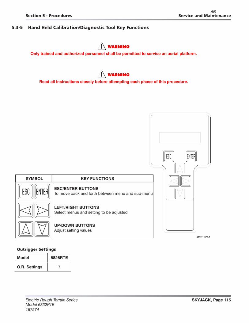
SKYJACK, Page 115Electric Rough Terrain SeriesModel 6832RTE167574
Section 5 - Procedures Service and Maintenance
5.3-5 Hand Held Calibration/Diagnostic Tool Key Functions
WARNING
Only trained and authorized personnel shall be permitted to service an aerial platform.
WARNING
Read all instructions closely before attempting each phase of this procedure.
KEY FUNCTIONSSYMBOL
ESC/ENTER BUTTONSTo move back and forth between menu and sub-menu
LEFT/RIGHT BUTTONSSelect menus and setting to be adjusted
UP/DOWN BUTTONSAdjust setting values
M62172AA
Outrigger Settings
Model 6826RTE
O.R. Settings 7
AB
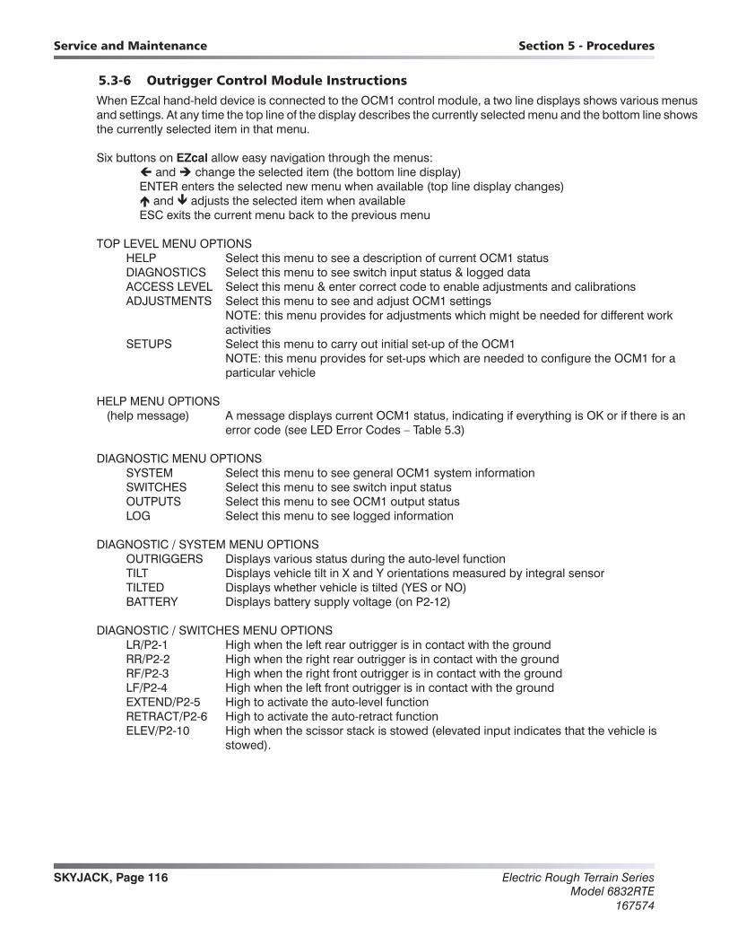
Electric Rough Terrain SeriesModel 6832RTE
167574
SKYJACK, Page 116
Section 5 - ProceduresService and Maintenance
5.3-6 Outrigger Control Module InstructionsWhen EZcal hand-held device is connected to the OCM1 control module, a two line displays shows various menus and settings. At any time the top line of the display describes the currently selected menu and the bottom line shows the currently selected item in that menu.
Six buttons on EZcal allow easy navigation through the menus: and change the selected item (the bottom line display) ENTER enters the selected new menu when available (top line display changes) and adjusts the selected item when available ESC exits the current menu back to the previous menu
TOP LEVEL MENU OPTIONS HELP Select this menu to see a description of current OCM1 status DIAGNOSTICS Select this menu to see switch input status & logged data ACCESS LEVEL Select this menu & enter correct code to enable adjustments and calibrations ADJUSTMENTS Select this menu to see and adjust OCM1 settings NOTE: this menu provides for adjustments which might be needed for different work
activities SETUPS Select this menu to carry out initial set-up of the OCM1 NOTE: this menu provides for set-ups which are needed to configure the OCM1 for a
particular vehicle
HELP MENU OPTIONS (help message) A message displays current OCM1 status, indicating if everything is OK or if there is an
error code (see LED Error Codes – Table 5.3)
DIAGNOSTIC MENU OPTIONS SYSTEM Select this menu to see general OCM1 system information SWITCHES Select this menu to see switch input status OUTPUTS Select this menu to see OCM1 output status LOG Select this menu to see logged information
DIAGNOSTIC / SYSTEM MENU OPTIONS OUTRIGGERS Displays various status during the auto-level function TILT Displays vehicle tilt in X and Y orientations measured by integral sensor TILTED Displays whether vehicle is tilted (YES or NO) BATTERY Displays battery supply voltage (on P2-12)
DIAGNOSTIC / SWITCHES MENU OPTIONS LR/P2-1 High when the left rear outrigger is in contact with the ground RR/P2-2 High when the right rear outrigger is in contact with the ground RF/P2-3 High when the right front outrigger is in contact with the ground LF/P2-4 High when the left front outrigger is in contact with the ground EXTEND/P2-5 High to activate the auto-level function RETRACT/P2-6 High to activate the auto-retract function ELEV/P2-10 High when the scissor stack is stowed (elevated input indicates that the vehicle is
stowed).
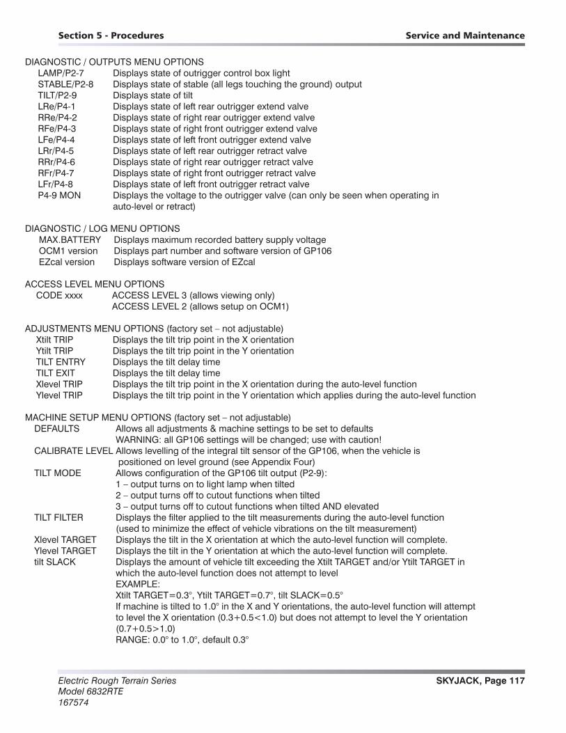
SKYJACK, Page 117Electric Rough Terrain SeriesModel 6832RTE167574
Section 5 - Procedures Service and Maintenance
DIAGNOSTIC / OUTPUTS MENU OPTIONS LAMP/P2-7 Displays state of outrigger control box light STABLE/P2-8 Displays state of stable (all legs touching the ground) output TILT/P2-9 Displays state of tilt LRe/P4-1 Displays state of left rear outrigger extend valve RRe/P4-2 Displays state of right rear outrigger extend valve RFe/P4-3 Displays state of right front outrigger extend valve LFe/P4-4 Displays state of left front outrigger extend valve LRr/P4-5 Displays state of left rear outrigger retract valve RRr/P4-6 Displays state of right rear outrigger retract valve RFr/P4-7 Displays state of right front outrigger retract valve LFr/P4-8 Displays state of left front outrigger retract valve P4-9 MON Displays the voltage to the outrigger valve (can only be seen when operating in
auto-level or retract)
DIAGNOSTIC / LOG MENU OPTIONS MAX.BATTERY Displays maximum recorded battery supply voltage OCM1 version Displays part number and software version of GP106 EZcal version Displays software version of EZcal
ACCESS LEVEL MENU OPTIONS CODE xxxx ACCESS LEVEL 3 (allows viewing only) ACCESS LEVEL 2 (allows setup on OCM1)
ADJUSTMENTS MENU OPTIONS (factory set – not adjustable) Xtilt TRIP Displays the tilt trip point in the X orientation Ytilt TRIP Displays the tilt trip point in the Y orientation TILT ENTRY Displays the tilt delay time TILT EXIT Displays the tilt delay time Xlevel TRIP Displays the tilt trip point in the X orientation during the auto-level function Ylevel TRIP Displays the tilt trip point in the Y orientation which applies during the auto-level function
MACHINE SETUP MENU OPTIONS (factory set – not adjustable) DEFAULTS Allows all adjustments & machine settings to be set to defaults WARNING: all GP106 settings will be changed; use with caution! CALIBRATE LEVEL Allows levelling of the integral tilt sensor of the GP106, when the vehicle is
positioned on level ground (see Appendix Four) TILT MODE Allows configuration of the GP106 tilt output (P2-9): 1 – output turns on to light lamp when tilted 2 – output turns off to cutout functions when tilted 3 – output turns off to cutout functions when tilted AND elevated TILT FILTER Displays the filter applied to the tilt measurements during the auto-level function
(used to minimize the effect of vehicle vibrations on the tilt measurement) Xlevel TARGET Displays the tilt in the X orientation at which the auto-level function will complete. Ylevel TARGET Displays the tilt in the Y orientation at which the auto-level function will complete. tilt SLACK Displays the amount of vehicle tilt exceeding the Xtilt TARGET and/or Ytilt TARGET in
which the auto-level function does not attempt to level EXAMPLE: Xtilt TARGET=0.3°, Ytilt TARGET=0.7°, tilt SLACK=0.5° If machine is tilted to 1.0° in the X and Y orientations, the auto-level function will attempt
to level the X orientation (0.3+0.5<1.0) but does not attempt to level the Y orientation (0.7+0.5>1.0)
RANGE: 0.0° to 1.0°, default 0.3°

Electric Rough Terrain SeriesModel 6832RTE
167574
SKYJACK, Page 118
Section 5 - ProceduresService and Maintenance
IMPORTANTEach phase must be completed before the next phase can be carried out. All phases must be completed before the aerial platform can be operated.
Always follow the instructions of the Calibration instrument.
1. Ensure aerial platform is parked on a firm and level surface.
2. Elevate the scissors high enough to lay a level across the base tubes. Ensure there is no debris on the base and the level sits flat. Do not elevate aerial platform higher than the high speed/tilt override limit switch.
3. Manually operate the outriggers and level the machine in 4 places: left side, right side, front and rear. All 4 outriggers must be firmly placed and all 4 tires are off the ground.
4. Double check that the aerial platform is level at all 4 points. 5. Connect the EZcal tool to the P1 connector on the CONTROL MODULE.
6. The display will show Help: Press Enter. By using Left/Right buttons, select the Access Level (3 ) from the menu and press the ENTER button.
7. The display will show Access Level: Code (0000). By using the Up/Down buttons, enter the Access Level Code (1 1 2 2) followed by pressing the ENTER
button.
8. The display will show Access Level 2. By using Left/Right buttons, select the Setups from the menu and press the ENTER button.
9. The display will show Setups: Change Defaults. Select the Change Defaults from the menu and press the ENTER button.
10. The display will show Defaults, 0 = Custom. By using Up/Down buttons, select the Defaults: Code Setting for your Model (For Default Code Refer to Table
5-3) from the menu and press the ENTER button and followed by ESCAPE button.
11. The display will show Setups Change Defaults. By using Left/Right buttons, select the Calibrate Level from the menu and press the ENTER.
12. The display will show Calibrate Level: Yes: Enter, No: ESC. Select the Yes from the menu by press the ENTER button.
13. The display will show Calibrate Level: Tilt 0.0 , 0.0’. Select the ESCAPE from the menu once.
14. The display will show Setups Calibrate Level. Select the ESCAPE from the menu once again.
15. The Calibration procedure is complete, unplug and remove the EZ-Cal.
16. Close the hydraulic/electric cabinet.
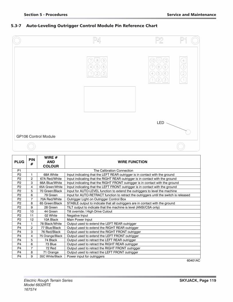
SKYJACK, Page 119Electric Rough Terrain SeriesModel 6832RTE167574
Section 5 - Procedures Service and Maintenance
5.3-7 Auto-Leveling Outrigger Control Module Pin Reference Chart
GP106 Control Module
LED
PLUG PIN #
WIRE # AND
COLOUR WIRE FUNCTION
P1 The Calibration Connection P2 1 68A White Input indicating that the LEFT REAR outrigger is in contact with the ground P2 2 67A Red/White Input indicating that the RIGHT REAR outrigger is in contact with the ground P2 3 66A Blue/White Input indicating that the RIGHT FRONT outrigger is in contact with the ground P2 4 65A Green/White Input indicating that the LEFT FRONT outrigger is in contact with the ground P2 5 70 Green/Black Input for AUTO-LEVEL function to extend the outriggers to level the machine P2 6 79 Green Input for AUTO-RETRACT function to retract the outriggers until the switch is released P2 7 70A Red/White Outrigger Light on Outrigger Control Box P2 8 65 Green/Black STABLE output to indicate that all outriggers are in contact with the ground P2 9 28 Green TILT output to indicate that the machine is level (ANSI/CSA only) P2 10 44 Green Tilt override / High Drive Cutout P2 11 02 White Negative Input P2 12 10A Black Main Power Input P4 1 78 Black/White Output used to extend the LEFT REAR outrigger P4 2 77 Blue/Black Output used to extend the RIGHT REAR outrigger P4 3 76 Red/Black Output used to extend the RIGHT FRONT outrigger P4 4 75 Orange/Black Output used to extend the LEFT FRONT outrigger P4 5 74 Black Output used to retract the LEFT REAR outrigger P4 6 73 Blue Output used to retract the RIGHT REAR outrigger P4 7 72 Red Output used to retract the RIGHT FRONT outrigger P4 8 71 Orange Output used to retract the LEFT FRONT outrigger P4 9 35C White/Black Power input for outriggers
60401AC
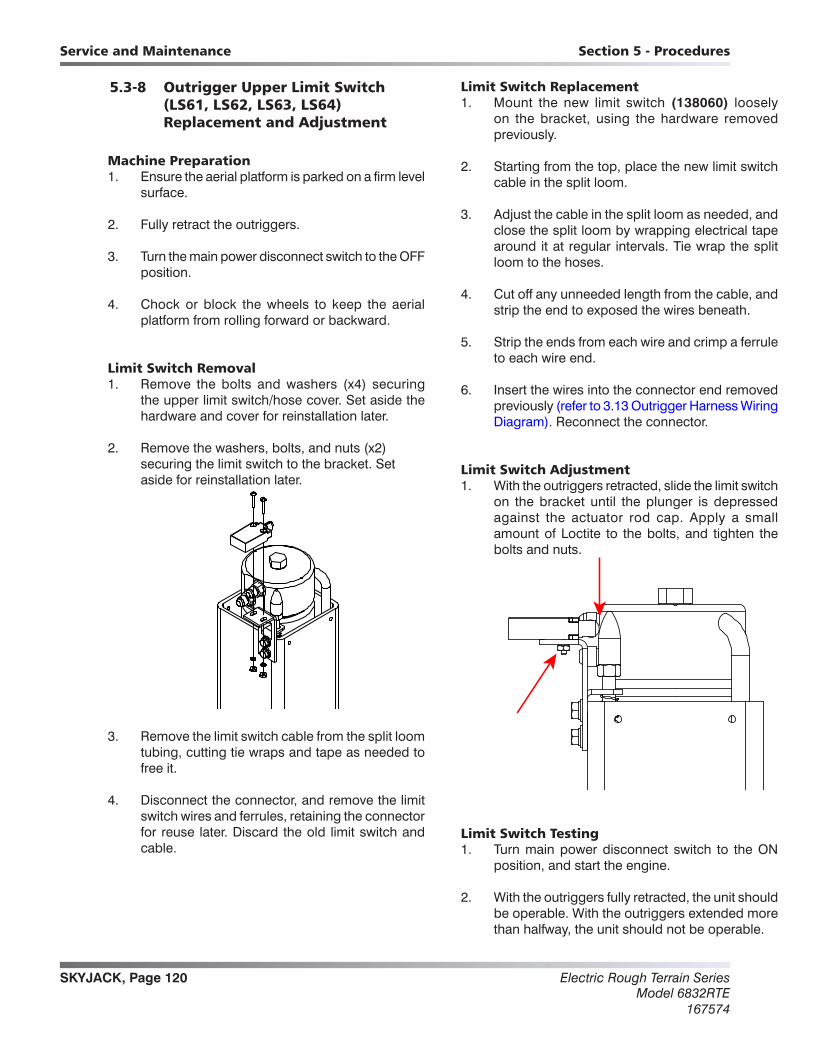
Electric Rough Terrain SeriesModel 6832RTE
167574
SKYJACK, Page 120
Section 5 - ProceduresService and Maintenance
5.3-8 Outrigger Upper Limit Switch (LS61, LS62, LS63, LS64) Replacement and Adjustment
Machine Preparation1. Ensure the aerial platform is parked on a firm level
surface.
2. Fully retract the outriggers.
3. Turn the main power disconnect switch to the OFF position.
4. Chock or block the wheels to keep the aerial platform from rolling forward or backward.
Limit Switch Removal1. Remove the bolts and washers (x4) securing
the upper limit switch/hose cover. Set aside the hardware and cover for reinstallation later.
2. Remove the washers, bolts, and nuts (x2) securing the limit switch to the bracket. Set aside for reinstallation later.
3. Remove the limit switch cable from the split loom tubing, cutting tie wraps and tape as needed to free it.
4. Disconnect the connector, and remove the limit switch wires and ferrules, retaining the connector for reuse later. Discard the old limit switch and cable.
Limit Switch Replacement 1. Mount the new limit switch (138060) loosely
on the bracket, using the hardware removed previously.
2. Starting from the top, place the new limit switch cable in the split loom.
3. Adjust the cable in the split loom as needed, and close the split loom by wrapping electrical tape around it at regular intervals. Tie wrap the split loom to the hoses.
4. Cut off any unneeded length from the cable, and strip the end to exposed the wires beneath.
5. Strip the ends from each wire and crimp a ferrule to each wire end.
6. Insert the wires into the connector end removed previously (refer to 3.13 Outrigger Harness Wiring Diagram). Reconnect the connector.
Limit Switch Adjustment1. With the outriggers retracted, slide the limit switch
on the bracket until the plunger is depressed against the actuator rod cap. Apply a small amount of Loctite to the bolts, and tighten the bolts and nuts.
Limit Switch Testing1. Turn main power disconnect switch to the ON
position, and start the engine.
2. With the outriggers fully retracted, the unit should be operable. With the outriggers extended more than halfway, the unit should not be operable.

SKYJACK, Page 121Electric Rough Terrain SeriesModel 6832RTE167574
Section 5 - Procedures Service and Maintenance
5.3-9 Outrigger Lower Limit Switch (LS65, LS66, LS67, LS68) Replacement and Adjustment
Machine Preparation1. Ensure the aerial platform is parked on a firm level
surface.
2. Fully retract the outriggers.
3. Turn the main power disconnect switch to the OFF position.
4. Chock or block the wheels to keep the aerial platform from rolling forward or backward.
Limit Switch Removal1. Remove the bolts and washers (x4) securing
the upper limit switch/hose cover. Set aside the hardware and cover for reinstallation later.
2. Remove the screws (x2) securing the lower limit switch cover. Set aside the hardware and cover for reinstallation later.
3. Remove the washers and screws (x2) securing the limit switch to the mount. Set aside for reinstallation later.
4. Cut the tie wraps and tape around the split loom as needed to expose the limit switch cable.
5. Disconnect the applicable wires from the connector, and cut the ferrules off of the wires on the end of the cable. Retain the connector for reuse later.
6. Remove the cable from the split loom. Gently pull the cable down through the outrigger weldment, and through the rubber grommet. Retain the rubber grommet. Discard the old limit switch and cable.
Limit Switch Replacement 1. Install a new limit switch (138059) to the mounting
block using the hardware removed earlier.
2. Feed the new cable through the rubber grommet, and place the grommet in the hole in the outrigger weldment.
3. Feed the cable up through the outrigger weldment, until it comes out the top.
4. Working from top to bottom, adjust the cable in the split loom and close the split loom by wrapping electrical tape around it at regular intervals. Tie wrap the split loom to the hoses.
5. Cut off any unneeded length from the cable, and strip the end to exposed the wires beneath.
6. Strips the ends from each wire and crimp a ferrule to each wire end.
7. Insert the wires into the connector end removed previously (refer to 3.13 Outrigger Harness Wiring Diagram). Reconnect the connector.
Limit Switch Adjustment 1. Loosen the bolts securing the mounting block to
the outrigger, and slide the block until the limit switch plunger is depressed halfway against the base weldment. Apply a small amount of Loctite to the bolts, and tighten them.

Electric Rough Terrain SeriesModel 6832RTE
167574
SKYJACK, Page 122
Section 5 - ProceduresService and Maintenance
Limit Switch Testing1. Turn main power disconnect switch on and start
the engine.
2. With the outriggers fully retracted, the unit should be operable. With the outriggers extended more than halfway, the unit should not be operable.
Scissors 5.4-1 High Speed Cutout Limit Switch (LS5)
Replacement and Adjustment
Machine Preparation1. Ensure the aerial platform is parked on a firm level
surface.
2. Chock or block the wheels to keep the aerial platform from rolling forward or backward.
Limit Switch Removal1. Raise the platform to give access to the limit switch
cable, and deploy the maintenance stand.
2. Turn the main power disconnect switch to the OFF position.
3. Remove the gear clamp securing the limit switch cover, and slide the limit switch cover off of the pin. Set aside the clamp for reinstallation later.
4. Remove the bolts, washers, and nuts (x2) securing the limit switch to the cover. Set the cover and hardware aside for reinstallation later.
5. Remove the limit switch and free the limit switch cable by cutting the tie wraps.
6. Follow the cable into the electrical panel, and disconnect the limit switch wires from the electrical panel. Discard the limit switch.
Limit Switch Replacement
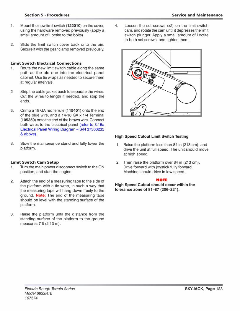
SKYJACK, Page 123Electric Rough Terrain SeriesModel 6832RTE167574
Section 5 - Procedures Service and Maintenance
1. Mount the new limit switch (122010) on the cover, using the hardware removed previously (apply a small amount of Loctite to the bolts).
2. Slide the limit switch cover back onto the pin. Secure it with the gear clamp removed previously.
Limit Switch Electrical Connections1. Route the new limit switch cable along the same
path as the old one into the electrical panel cabinet. Use tie wraps as needed to secure them at regular intervals.
2 Strip the cable jacket back to separate the wires. Cut the wires to length if needed, and strip the ends.
3. Crimp a 18 GA red ferrule (115401) onto the end of the blue wire, and a 14-16 GA x 1/4 Terminal (105359) onto the end of the brown wire. Connect both wires to the electrical panel (refer to 3.16a Electrical Panel Wiring Diagram – S/N 37300235 & above).
3. Stow the maintenance stand and fully lower the platform.
Limit Switch Cam Setup1. Turn the main power disconnect switch to the ON
position, and start the engine.
2. Attach the end of a measuring tape to the side of the platform with a tie wrap, in such a way that the measuring tape will hang down freely to the ground. Note: The end of the measuring tape should be level with the standing surface of the platform.
3. Raise the platform until the distance from the standing surface of the platform to the ground measures 7 ft (2.13 m).
4. Loosen the set screws (x2) on the limit switch cam, and rotate the cam until it depresses the limit switch plunger. Apply a small amount of Loctite to both set screws, and tighten them.
High Speed Cutout Limit Switch Testing
1. Raise the platform less than 84 in (213 cm), and drive the unit at full speed. The unit should move at high speed.
2. Then raise the platform over 84 in (213 cm). Drive forward with joystick fully forward. Machine should drive in low speed.
NOTE High Speed Cutout should occur within the tolerance zone of 81–87 (206–221).

Electric Rough Terrain SeriesModel 6832RTE
167574
SKYJACK, Page 124
Section 5 - ProceduresService and Maintenance
5.5-1 Gate Springe Hinge Adjustment
1. The tension of the spring hinges should be such that when the gate is opened halfway and released, it will close fully and latch.
2. To adjust the tension of the spring hinges, first remove the safety locking screw located at the top or bottom of each hinge. Retain the screws for reinstallation later.
3. To increase the tension, insert a 5/32 hex wrench in the screw socket, and turn the wrench clockwise. To release the tension, depress the hex wrench in the socket, let it rotate counterclockwise, then release the hex wrench.
4. Adjust the tension on both hinges until the gate releases and latches from a half open position.
5. Reinstall the safety locking screws into the hinges when tension adjustment is complete.

SKYJACK, Page 125Electric Rough Terrain SeriesModel 6832RTE167574
Notes

www.skyjack.com