model sk-fft
TRANSCRIPT

Model SK-FFTFire Fighter’s TelephoneInstallation/Operation Manual
Document 54711 Rev: B212/18/2020 ECN: 2907

2 Model SK-FFT Manual — P/N 54711:B2 12/18/2020
Fire Alarm & Emergency Communication System LimitationsWhile a life safety system may lower insurance rates, it is not a substitute for life and property insurance!
An automatic fire alarm system—typically made up of smoke detectors, heat detectors, manual pull stations, audible warning devices, and a fire alarm control panel (FACP) with remote notification capability—can provide early warning of a developing fire. Such a system, however, does not assure protection against property damage or loss of life resulting from a fire. An emergency communication system—typically made up of an automatic fire alarm system (as described above) and a life safety communication system that may include an autonomous control unit (ACU), local operating console (LOC), voice communication, and other various interoperable communication methods—can broadcast a mass notification message. Such a system, however, does not assure protection against property damage or loss of life resulting from a fire or life safety event. The Manufacturer recommends that smoke and/or heat detectors be located throughout a protected premises following the recommendations of the current edition of the National Fire Protection Association Standard 72 (NFPA 72), manufacturer's recommendations, State and local codes, and the recommendations contained in the Guide for Proper Use of System Smoke Detectors, which is made available at no charge to all installing dealers. This document can be found at http://www.systemsensor.com/appguides/. A study by the Federal Emergency Management Agency (an agency of the United States government) indicated that smoke detectors may not go off in as many as 35% of all fires. While fire alarm systems are designed to provide early warning against fire, they do not guarantee warning or protection against fire. A fire alarm system may not provide timely or adequate warning, or simply may not function, for a variety of reasons: Smoke detectors may not sense fire where smoke cannot reach the detectors such as in chimneys, in or behind walls, on roofs, or on the other side of closed doors. Smoke detectors also may not sense a fire on another level or floor of a building. A second-floor detector, for example, may not sense a first-floor or basement fire. Particles of combustion or “smoke” from a developing fire may not reach the sensing chambers of smoke detectors because:• Barriers such as closed or partially closed doors, walls, chimneys,
even wet or humid areas may inhibit particle or smoke flow. • Smoke particles may become “cold,” stratify, and not reach the
ceiling or upper walls where detectors are located. • Smoke particles may be blown away from detectors by air outlets,
such as air conditioning vents. • Smoke particles may be drawn into air returns before reaching the
detector. The amount of “smoke” present may be insufficient to alarm smoke detectors. Smoke detectors are designed to alarm at various levels of smoke density. If such density levels are not created by a developing fire at the location of detectors, the detectors will not go into alarm. Smoke detectors, even when working properly, have sensing limitations. Detectors that have photoelectronic sensing chambers tend to detect smoldering fires better than flaming fires, which have little visible smoke. Detectors that have ionizing-type sensing chambers tend to detect fast-flaming fires better than smoldering fires. Because fires develop in different ways and are often unpredictable in their growth, neither type of detector is necessarily best and a given type of detector may not provide adequate warning of a fire. Smoke detectors cannot be expected to provide adequate warning of fires caused by arson, children playing with matches (especially in bedrooms), smoking in bed, and violent explosions (caused by escaping gas, improper storage of flammable materials, etc.). Heat detectors do not sense particles of combustion and alarm only when heat on their sensors increases at a predetermined rate or reaches a predetermined level. Rate-of-rise heat detectors may be subject to reduced sensitivity over time. For this reason, the rate-of-rise feature of each detector should be tested at least once per year by a qualified fire protection specialist. Heat detectors are designed to protect property, not life.
IMPORTANT! Smoke detectors must be installed in the same room as the control panel and in rooms used by the system for the connection of alarm transmission wiring, communications, signaling, and/or power. If detectors are not so located, a developing fire may damage the alarm system, compromising its ability to report a fire. Audible warning devices such as bells, horns, strobes, speakers and displays may not alert people if these devices are located on the other side of closed or partly open doors or are located on another floor of a building. Any warning device may fail to alert people with a disability or those who have recently consumed drugs, alcohol, or medication. Please note that:• An emergency communication system may take priority over a fire
alarm system in the event of a life safety emergency.• Voice messaging systems must be designed to meet intelligibility
requirements as defined by NFPA, local codes, and Authorities Having Jurisdiction (AHJ).
• Language and instructional requirements must be clearly dissemi-nated on any local displays.
• Strobes can, under certain circumstances, cause seizures in peo-ple with conditions such as epilepsy.
• Studies have shown that certain people, even when they hear a fire alarm signal, do not respond to or comprehend the meaning of the signal. Audible devices, such as horns and bells, can have dif-ferent tonal patterns and frequencies. It is the property owner's responsibility to conduct fire drills and other training exercises to make people aware of fire alarm signals and instruct them on the proper reaction to alarm signals.
• In rare instances, the sounding of a warning device can cause temporary or permanent hearing loss.
A life safety system will not operate without any electrical power. If AC power fails, the system will operate from standby batteries only for a specified time and only if the batteries have been properly maintained and replaced regularly. Equipment used in the system may not be technically compatible with the control panel. It is essential to use only equipment listed for service with your control panel. Alarm Signaling Communications:• IP connections rely on available bandwidth, which could be lim-
ited if the network is shared by multiple users or if ISP policies impose restrictions on the amount of data transmitted. Service packages must be carefully chosen to ensure that alarm signals will always have available bandwidth. Outages by the ISP for maintenance and upgrades may also inhibit alarm signals. For added protection, a backup cellular connection is recommended.
• Cellular connections rely on a strong signal. Signal strength can be adversely affected by the network coverage of the cellular car-rier, objects and structural barriers at the installation location. Uti-lize a cellular carrier that has reliable network coverage where the alarm system is installed. For added protection, utilize an external antenna to boost the signal.
• Telephone lines needed to transmit alarm signals from a premise to a central monitoring station may be out of service or temporarily disabled. For added protection against telephone line failure, backup alarm signaling connections are recommended.
The most common cause of life safety system malfunction is inadequate maintenance. To keep the entire life safety system in excellent working order, ongoing maintenance is required per the manufacturer's recommendations, and UL and NFPA standards. At a minimum, the requirements of NFPA 72 shall be followed. Environments with large amounts of dust, dirt, or high air velocity require more frequent maintenance. A maintenance agreement should be arranged through the local manufacturer's representative. Maintenance should be scheduled as required by National and/or local fire codes and should be performed by authorized professional life safety system installers only. Adequate written records of all inspections should be kept.
Limit-F-2020

Model SK-FFT Manual — P/N 54711:B2 12/18/2020 3
Installation PrecautionsAdherence to the following will aid in problem-free installation with long-term reliability:WARNING - Several different sources of power can be con-nected to the fire alarm control panel. Disconnect all sources of power before servicing. Control unit and associated equipment may be damaged by removing and/or inserting cards, modules, or inter-connecting cables while the unit is energized. Do not attempt to install, service, or operate this unit until manuals are read and under-stood.
CAUTION - System Re-acceptance Test after Software Changes: To ensure proper system operation, this product must be tested in accordance with NFPA 72 after any programming operation or change in site-specific software. Re-acceptance testing is required after any change, addition or deletion of system components, or after any modification, repair or adjustment to system hardware or wiring. All components, circuits, system operations, or software functions known to be affected by a change must be 100% tested. In addition, to ensure that other operations are not inadvertently affected, at least 10% of initiating devices that are not directly affected by the change, up to a maximum of 50 devices, must also be tested and proper system operation verified.
This system meets NFPA requirements for operation at 0-49º C/32-120º F and at a relative humidity 93% ± 2% RH (non-condensing) at 32°C ± 2°C (90°F ± 3°F). However, the useful life of the system's standby batteries and the electronic components may be adversely affected by extreme temperature ranges and humidity. Therefore, it is recommended that this system and its peripherals be installed in an environment with a normal room temperature of 15-27º C/60-80º F.
Verify that wire sizes are adequate for all initiating and indicating device loops. Most devices cannot tolerate more than a 10% I.R. drop from the specified device voltage.
Like all solid state electronic devices, this system may operate erratically or can be damaged when subjected to lightning induced transients. Although no system is completely immune from lightning transients and interference, proper grounding will reduce susceptibil-ity. Overhead or outside aerial wiring is not recommended, due to an increased susceptibility to nearby lightning strikes. Consult with the Technical Services Department if any problems are anticipated or encountered.
Disconnect AC power and batteries prior to removing or inserting circuit boards. Failure to do so can damage circuits.
Remove all electronic assemblies prior to any drilling, filing, ream-ing, or punching of the enclosure. When possible, make all cable entries from the sides or rear. Before making modifications, verify that they will not interfere with battery, transformer, or printed circuit board location.
Do not tighten screw terminals more than 9 in-lbs. Over-tightening may damage threads, resulting in reduced terminal contact pressure and difficulty with screw terminal removal.
This system contains static-sensitive components. Always ground yourself with a proper wrist strap before handling any circuits so that static charges are removed from the body. Use static sup-pressive packaging to protect electronic assemblies removed from the unit.
Units with a touchscreen display should be cleaned with a dry, clean, lint free/microfiber cloth. If additional cleaning is required, apply a small amount of Isopropyl alcohol to the cloth and wipe clean. Do not use detergents, solvents, or water for cleaning. Do not spray liquid directly onto the display.
Follow the instructions in the installation, operating, and program-ming manuals. These instructions must be followed to avoid damage to the control panel and associated equipment. FACP operation and reliability depend upon proper installation.
Precau-D2-11-2017
FCC WarningWARNING: This equipment generates, uses, and can radi-ate radio frequency energy and if not installed and used in accordance with the instruction manual may cause interfer-ence to radio communications. It has been tested and found to comply with the limits for Class A computing devices pur-suant to Subpart B of Part 15 of FCC Rules, which is designed to provide reasonable protection against such interference when devices are operated in a commercial environment. Operation of this equipment in a residential area is likely to cause interference, in which case the user will be required to correct the interference at his or her own expense.
Canadian RequirementsThis digital apparatus does not exceed the Class A limits for radiation noise emissions from digital apparatus set out in the Radio Interference Regulations of the Canadian Depart-ment of Communications.
Le present appareil numerique n'emet pas de bruits radio-electriques depassant les limites applicables aux appareils numeriques de la classe A prescrites dans le Reglement sur le brouillage radioelectrique edicte par le ministere des Communications du Canada.
eVance®, Flexput®, Honeywell®, JumpStart®, Silent Knight®, and SWIFT® are registered trademarks of Honeywell International Inc. Microsoft® and Windows® areregistered trademarks of the Microsoft Corporation. Chrome™ and Google™ are trademarks of Google Inc. Firefox® is a registered trademark of The Mozilla Foundation. ©2021. All rights reserved. Unauthorized use of this document is strictly prohibited.

4 Model SK-FFT Manual — P/N 54711:B2 12/18/2020
Software DownloadsIn order to supply the latest features and functionality in fire alarm and life safety technology to our customers, we make frequent upgrades to the embedded software in our products. To ensure that you are installing and programming the latest features, we strongly recommend that you download the most current version of software for each product prior to commissioning any system. Contact Technical Support with any questions about software and the appropriate version for a specific application.
Documentation FeedbackYour feedback helps us keep our documentation up-to-date and accurate. If you have any comments or suggestions about our online Help or printed manuals, you can email us.
Please include the following information:
• Product name and version number (if applicable)• Printed manual or online Help• Topic Title (for online Help)• Page number (for printed manual)• Brief description of content you think should be improved or corrected• Your suggestion for how to correct/improve documentation
Send email messages to:
Please note this email address is for documentation feedback only. If you have any technical issues, please contact Technical Services.
This symbol (shown left) on the product(s) and / or accompanying documents means that used electrical and electronic products should not be mixed with general household waste. For proper treatment, recovery and recycling, contact your local authorities or dealer and ask for the correct method of disposal.
Electrical and electronic equipment contains materials, parts and substances, which can be dangerous to the environment and harmful to human health if the waste of electrical and electronic equipment (WEEE) is not disposed of correctly.

Table of ContentsSection 1: Overview .......................................................................................................................................................... 7
1.1: Features..............................................................................................................................................................................................................71.2: Optional Accessories .........................................................................................................................................................................................71.3: Agency Requirements ........................................................................................................................................................................................7
1.3.1: UL 864 9th and 10th Edition ..................................................................................................................................................................71.4: About This Manual ............................................................................................................................................................................................7
Section 2: Prerequisites for Installation.......................................................................................................................... 82.1: Environmental Specifications ............................................................................................................................................................................82.2: Preventing Water Damage .................................................................................................................................................................................8
2.2.1: Removing the SK-FFT Assembly from the Housing .............................................................................................................................82.3: SK-FFT Board Layout .......................................................................................................................................................................................82.4: Electrical Specifications ..................................................................................................................................................................................10
2.4.1: Power Requirements.............................................................................................................................................................................102.4.2: Current Ratings.....................................................................................................................................................................................10
2.5: Wiring Specifications.......................................................................................................................................................................................102.6: Wire Routing....................................................................................................................................................................................................10
Section 3: Installation ..................................................................................................................................................... 123.1: Mounting the Cabinet ......................................................................................................................................................................................12
3.1.1: Surface Mounting .................................................................................................................................................................................123.1.2: Flush Mounting.....................................................................................................................................................................................12
3.2: Installing the Fire Fighter’s Hand Set..............................................................................................................................................................143.3: FFT-24 Installation ..........................................................................................................................................................................................153.4: Installing the SK-FFT ......................................................................................................................................................................................163.5: Operating Power ..............................................................................................................................................................................................163.6: DIP switch settings on SK-FFT .......................................................................................................................................................................16
3.6.1: DIP Switch ...........................................................................................................................................................................................163.7: SK-FFT Fire Fighter Telephone Module Connection......................................................................................................................................173.8: FFT-FPJ Installation ........................................................................................................................................................................................183.9: Installation of FFT-STS ...................................................................................................................................................................................18
3.9.1: Assembly of Units with Coiled Cord Handsets....................................................................................................................................18
Section 4: SLC Device Installation................................................................................................................................. 204.1: List of SLC Devices.........................................................................................................................................................................................204.2: Maximum Number of Devices ........................................................................................................................................................................204.3: Wiring Requirements for SLC Device.............................................................................................................................................................20
4.3.1: Wiring SLC in (Class B) Configuration ...............................................................................................................................................204.3.2: Wiring SLC Devices in (Class A) Configuration .................................................................................................................................21
4.4: Addressing SK-MINIMON SLC Devices .......................................................................................................................................................22
Section 5: Audio Phone Circuit Installation.................................................................................................................. 235.1: List of Devices .................................................................................................................................................................................................235.2: Maximum Number of Devices .......................................................................................................................................................................235.3: Wiring Requirements for the Audio Telephone Circuit ...................................................................................................................................23
5.3.1: Single Phone Jack Audio Circuit in Class B Configuration .................................................................................................................235.3.2: Single Phone Jack Audio Circuit Wired in Class A Configuration......................................................................................................245.3.3: Multi-Phone Jack Audio Circuit Wired in Class B Configuration .......................................................................................................255.3.4: Multi-Phone Jack Audio Circuit in Class A Configuration..................................................................................................................265.3.5: Telephone Jack Only Audio Circuit .....................................................................................................................................................26
Section 6: System Operation.......................................................................................................................................... 286.1: Key Switch Operations ....................................................................................................................................................................................28
6.1.1: JumpStart Key Switch (on inside of FFT Dead Front Panel). ..............................................................................................................286.1.2: Accept Key Switch (on inside of FFT dead front panel)......................................................................................................................286.1.3: Answer Switch .....................................................................................................................................................................................286.1.4: Silence Switch ......................................................................................................................................................................................28
6.2: LED Operations ...............................................................................................................................................................................................286.2.1: Power Status LED.................................................................................................................................................................................286.2.2: Answer..................................................................................................................................................................................................286.2.3: Power ....................................................................................................................................................................................................286.2.4: Local Handset Trouble .........................................................................................................................................................................286.2.5: Remote Handset Trouble .....................................................................................................................................................................28
Model SK-FFT Manual — P/N 54711:B2 12/18/2020 5

Table of Contents
6.2.6: General Trouble ....................................................................................................................................................................................286.2.7: Status LEDs (on Inside of FFT dead front panel).................................................................................................................................286.2.8: Zone Active ..........................................................................................................................................................................................286.2.9: Zone Trouble ........................................................................................................................................................................................29
6.3: JumpStart® Operation .....................................................................................................................................................................................29
Appendix A: Compatible Powering Devices ................................................................................................................. 30A.1: Compatible Power Devices.............................................................................................................................................................................30
6 Model SK-FFT Manual — P/N 54711:B2 12/18/2020

Model SK-FFT Manual — P/N 54711:B2 12/18/2020 7
Section 1: OverviewAn SK-FFT Fire Fighter Telephone System provides supervision, annunciation, and control for local and remote telephone handsets. The SK-FFT with keypad, provides indications of phone activation, and corresponding trouble conditions. Additionally, up to 48 telephone cir-cuits can be annunciated at the SK-FFT by connecting the FFT-24 zone expander.
1.1 Features• One Form-C Trouble Relay• System Trouble Relay - TB6• SK-FFT Fire Fighter Telephone module for control and annunciation of up to 48 remote telephone jacks• A maximum of 10 Fire Fighter Remote Handsets (FFT-RHS) can be used at one time to communicate over the telephone circuit
connected to the SK-FFT• Fire Fighter Phone Jack (FFT-FPJ) provides a plug-in location for the FFT-RHS• Single Telephone Station (FFT-STS)• Fire Fighter Handset Cabinet (FFT-HSC) is used to store ten Fire Fighter Handsets (FFT-RHS)• System Status LEDs• Supports a single FFT-24 zone expander
1.2 Optional AccessoriesThis manual also contains information on how to install the following compatible accessories with the FFT series equipment:
1.3 Agency RequirementsThe SK-FFT has the same requirements as the main control panel. These requirements are listed in the Honeywell Silent Knight Series Addressable FACP Installation Manuals. The FACP Installation Manuals can be found on the web site at www.silentknight.com.
1.3.1 UL 864 9th and 10th Edition • Per the UL Continuing Certification Program, UL 864 9th edition fire alarm control equipment will retain certification
after the roll-out of UL 10th edition (12/2/2018). Installations of UL 864 10th Edition certified equipment are permitted to use UL864 9th Edition certified equipment when approved by the local Authority Having Jurisdiction (AHJ).
1.4 About This ManualThis manual is intended to be a complete reference for all installation and operations tasks for the SK-FFT. Honeywell Farenhyt series Instal-lation Manuals can be found on our web site at www.silentknight.com.Please let us know if the manual does not meet your needs in any way. We value your feedback!
Model Number DescriptionFFT-24 24 Zone ExpanderFFT-FPJ Remote Phone JackFFT-RHS Fire Fighters Remote Hand SetFFT-HSC Fire Fighters Handset CabinetFFT-STSR Single Telephone Station RecessedFFT-STSS Single Telephone Station Surface MountFFT-BGK Break Glass Kit for FFT-STSSK-MINIMON Addressable Mini-Monitor ModuleSK-ISO SLC Line Isolation Module
Table 1.1 Optional Accessories

Section 2: Prerequisites for InstallationThis section of the manual is intended to help you plan your tasks to complete the installation. Please read this section thor-oughly, especially if you are installing a SK-FFT for the first time.
2.1 Environmental SpecificationsIt is important to protect the SK-FFT control panel from water. To prevent water damage, the following conditions should be AVOIDED when installing the units:• Do not mount directly on exterior walls, especially masonry walls (condensation)• Do not mount directly on exterior walls below grade (condensation)• Protect from plumbing leaks• Protect from splash caused by sprinkler system inspection ports• Do not mount in areas with humidity-generating equipment (such as dryers, production machinery)When selecting a location to mount the SK-FFT, the unit should be mounted where it will NOT be exposed to temperatures outside the range of 0°C- 49°C (32°F-120°F) or humidity outside the range of 10% - 93% at 30°C (86°F) non-condensing.
2.2 Preventing Water DamageWater damage to the fire fighters phone system can be caused by moisture entering the cabinet through the conduits. Conduits that are installed to enter the top of the cabinet are most likely to cause water problems. Installers should take reasonable pre-cautions to prevent water from entering the cabinet. Water damage is not covered under warranty.
2.2.1 Removing the SK-FFT Assembly from the HousingIf it should ever be necessary to remove the control panel assembly from the cabinet for repair, do so by removing the screws that hold the control panel in to the cabinet. Do not attempt to disassemble the circuit boards.
2.3 SK-FFT Board LayoutFigure 2.1 illustrates the SK-FFT board layout and terminal information.
Figure 2.1 SK-FFT Back View
JumpStart Accept
Connector for FFT-24
Status LED’s
LocalHandset
PZT
Phone In
Phone Out
SLC IN
SLC Out
mounting stud
Mounting stud
Supervised Power Limited
All circuits inherently power limited except the trouble relay
DIP Switch
Not used
DCPower
Non Power Limited
mounting stud
mounting stud
Mounting stud
mounting stud
Power Status LED
TroubleRelay
8 Model SK-FFT Manual — P/N 54711:B2 12/18/2020

SK-FFT Board Layout Prerequisites for Installation
Figure 2.3 shows the circuit board that attaches to the cabinet. If you need to remove the board assembly for repair, remove the seven mounting nuts which hold the assembly in the cabinet. Then, lift the control board out of the cabinet.
Figure 2.2 SK-FFT Front View
Figure 2.3 FFT-24 Expander Front View for Zone 25 - 48
Active(green)
Trouble(amber)
Zone 1-Zone 8
Zone 9 -Zone 16
Answer LED General Trouble LED
Zone 17 -Zone 24
Zone 25 -Zone 32
Zone 33 -Zone 40 Zone 41-
Zone 48
Active(green)Trouble(amber)
Model SK-FFT Manual — P/N 54711:B2 12/18/2020 9
Prerequisites for Installation Electrical Specifications
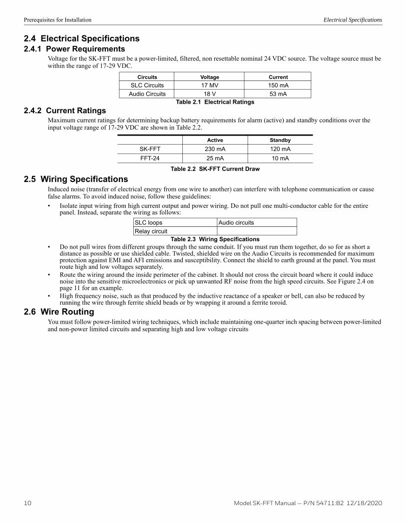
2.4 Electrical Specifications2.4.1 Power Requirements
Voltage for the SK-FFT must be a power-limited, filtered, non resettable nominal 24 VDC source. The voltage source must be within the range of 17-29 VDC.
2.4.2 Current RatingsMaximum current ratings for determining backup battery requirements for alarm (active) and standby conditions over the input voltage range of 17-29 VDC are shown in Table 2.2.
2.5 Wiring SpecificationsInduced noise (transfer of electrical energy from one wire to another) can interfere with telephone communication or cause false alarms. To avoid induced noise, follow these guidelines:• Isolate input wiring from high current output and power wiring. Do not pull one multi-conductor cable for the entire
panel. Instead, separate the wiring as follows:
• Do not pull wires from different groups through the same conduit. If you must run them together, do so for as short a distance as possible or use shielded cable. Twisted, shielded wire on the Audio Circuits is recommended for maximum protection against EMI and AFI emissions and susceptibility. Connect the shield to earth ground at the panel. You must route high and low voltages separately.
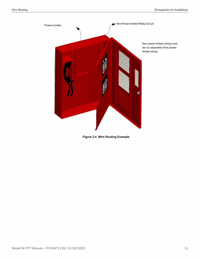
• Route the wiring around the inside perimeter of the cabinet. It should not cross the circuit board where it could induce noise into the sensitive microelectronics or pick up unwanted RF noise from the high speed circuits. See Figure 2.4 on page 11 for an example.
• High frequency noise, such as that produced by the inductive reactance of a speaker or bell, can also be reduced by running the wire through ferrite shield beads or by wrapping it around a ferrite toroid.
2.6 Wire RoutingYou must follow power-limited wiring techniques, which include maintaining one-quarter inch spacing between power-limited and non-power limited circuits and separating high and low voltage circuits
Circuits Voltage CurrentSLC Circuits 17 MV 150 mA
Audio Circuits 18 V 53 mATable 2.1 Electrical Ratings
Active StandbySK-FFT 230 mA 120 mAFFT-24 25 mA 10 mA
Table 2.2 SK-FFT Current Draw
SLC loops Audio circuitsRelay circuit
Table 2.3 Wiring Specifications
10 Model SK-FFT Manual — P/N 54711:B2 12/18/2020
Wire Routing Prerequisites for Installation
.
Figure 2.4 Wire Routing Example
Non-Power-limited Relay CircuitPower-Limited
Non power-limited wiring must be run separately from power-limited wiring.
Model SK-FFT Manual — P/N 54711:B2 12/18/2020 11

Section 3: Installation3.1 Mounting the Cabinet
Read the environmental specifications in Section 2.1 before mounting the SK-FFT cabinet. This will ensure that you select a suitable location.The cabinet can be surface or flush mounted. Do NOT flush-mount in a wall designed as a fire break.
3.1.1 Surface MountingThe Cabinet can be mounted on the wall surface by using the mounting holes in the back of the cabinet (see Figure 3.1 on page 12). 1. Insert two screws level with each other, 14" apart for the top cabinet key shaped holes. See Figure 3.1 on page 12.2. Hang the cabinet onto the two screws. Tighten the screws down.3. Insert two screws into the two bottom mounting holes and tighten them snug to the cabinet.
Figure 3.1 Cabinet Mounting Holes
3.1.2 Flush MountingThis section describes how to flush mount the cabinet into a wall. To recess mount the cabinet you will need to have the optional trim ring P/N VIP-TR (ordered separately). Follow these steps to recess mount the cabinet:1. Remove the cabinet door and the dead front panel. 2. Cut a recess hole 20-1/4” W x 26-3/4” H (51.44 cm W x 67.95 cm H). There should be 1.5" to 1.75" of cabinet extruding
from the wall, this should be measured from either the top edge or bottom edge to the exterior side of the sheet rock. (See Figure 3.2.)
NOTE: Do not insert the cabinet deeper than recommend above. If the cabinet is mounted to deep you will not be able to re-attach the door assembly.
3. Mount the cabinet to wall studs by inserting a screw through the cabinets side mounting holes into the wall stud.
Bottom Mounting Holes
20"
26-½”
Key Shaped Holes
12 Model SK-FFT Manual — P/N 54711:B2 12/18/2020

Mounting the Cabinet Installation
Figure 3.2 Detail of Flush Mounting with Trim Ring4. Place the trim ring around the cabinet. See Figure 3.3..
Figure 3.3 Trim Ring Around cabinet5. Secure the trim ring to the cabinet using the self-tapping sheet metal screws from the inside of the cabinet into the trim
ring. 6. Re-attach the cabinet door assembly.
Side View of Cabinet
Sheet Rock
Sheet Rock
MountingStuds
CabinetMounting Hole
Trim Ring MountingHole
CabinetMounting Hole
and Trim Ring
Trim Ring
1.5 to 1.75"
Trim Ring MountingHole
Trim Ring
Cabinet
Model SK-FFT Manual — P/N 54711:B2 12/18/2020 13

Installation Installing the Fire Fighter’s Hand Set
Cabinet Door and Dead Front RemovalWhile installing the cabinet it may be necessary to remove the cabinet door and the dead front panel. This section provides instructions on how to remove the door and dead front panel.1. Using a Phillips head screw driver, remove the six screws that hold the dead front panel in place. See Figure 3.4..
Figure 3.4 Cabinet Door and Dead Front Panel Removal2. Using a 1/4” Hex drive, remove the six Hex nuts that hold the cabinet door in place. See Figure 3.4. Re-Attaching the Cabinet DoorTo re-attach the cabinet door reverse the procedure in section .
3.2 Installing the Fire Fighter’s Hand Set FFT Local Handset installation involves the following steps:1. Insert phone cord through hole of dead front panel. See Figure 3.5.
Figure 3.5 Handset Cord Inserted Through Dead Front Panel Hole
Cabinet Door
Dead Front Panel
Dead FrontPanel Screws
Cabinet DoorHex Nuts
14 Model SK-FFT Manual — P/N 54711:B2 12/18/2020
FFT-24 Installation Installation
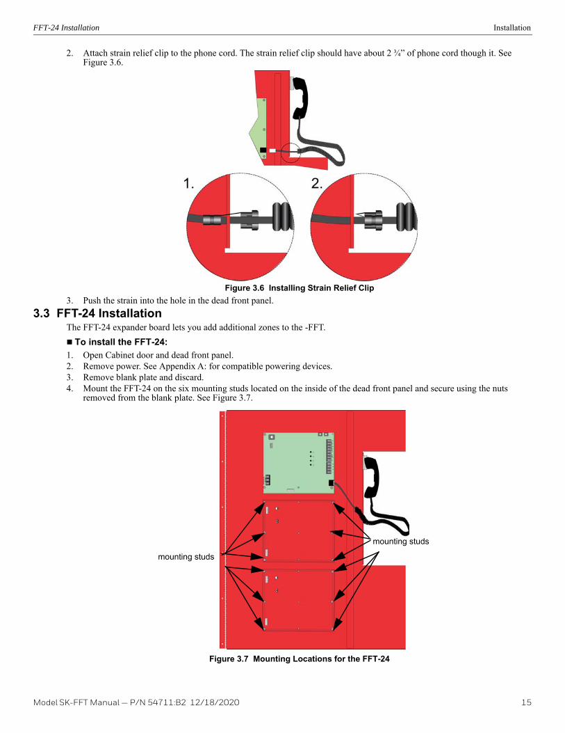
2. Attach strain relief clip to the phone cord. The strain relief clip should have about 2 ¾” of phone cord though it. See Figure 3.6.
Figure 3.6 Installing Strain Relief Clip3. Push the strain into the hole in the dead front panel.
3.3 FFT-24 InstallationThe FFT-24 expander board lets you add additional zones to the -FFT. To install the FFT-24:1. Open Cabinet door and dead front panel.2. Remove power. See Appendix A: for compatible powering devices.3. Remove blank plate and discard.4. Mount the FFT-24 on the six mounting studs located on the inside of the dead front panel and secure using the nuts
removed from the blank plate. See Figure 3.7.
Figure 3.7 Mounting Locations for the FFT-24
mounting studs
mounting studs
Model SK-FFT Manual — P/N 54711:B2 12/18/2020 15

Installation Installing the SK-FFT
5. Connect one end of the wiring harness (P/N 130398 supplied) to the SK-FFT and the other end to the FFT-24 as shown in Figure 3.8.
Figure 3.8 Wire Harness Connection from SK-FFT to FFT-24 Zones 25- 486. Restore power. See Section 3.5.
3.4 Installing the SK-FFTSK-FFT installation involves the following steps:• Make physical connection to any outputs that will power* the SK-FFT. (See Section 3.5).• Set the DIP switch ID for the SK-FFT (See Section 3.6.1).*See Appendix A: in the back of this manual for compatible powering devices. Manuals can also be found on the website www.silentknight.com.
3.5 Operating Power This section provides instructions to install the appropriate DC power source.1. Connect the SK-FFT to the appropriate DC power source. See Section 2.4.1 for power requirements. For compatible
product see Appendix A.2. Use the on-board DIP switch to assign the configuration setting to the SK-FFT. (See Section 3.6.1).
3.6 DIP switch settings on SK-FFTThis section describes how to configure the DIP switch setting on the SK-FFT.1. Refer to Section 2.3 for location of the DIP switches on the SK-FFT board.2. Configure the SK-FFT module by adding it to the system through JumpStart feature. See Section 6.3 for JumpStart
Operation. Table 3.1 list possible DIP switch configurations.
3.6.1 DIP Switch
Figure 3.9 DIP Switch
SK-FFT
DIP Switch ON OFF
1 SLC Devices Installed SLC Devices not Installed2 Trouble PZT Enabled Trouble PZT Disabled
3 SLC Class A Supervision SLC Class B Supervision4 Phone Circuit Class A Supervision Phone Circuit Class B Supervision
5 First FFT-24 Expander Installed First FFT-24 Expander not InstalledTable 3.1 SK-FFT DIP Switch Configurations
16 Model SK-FFT Manual — P/N 54711:B2 12/18/2020

SK-FFT Fire Fighter Telephone Module Connection Installation
3.7 SK-FFT Fire Fighter Telephone Module ConnectionThe SK-FFT provides connection for a single Class B or Class A telephone audio circuit. See Section 4 and Section 5 for examples of audio zone configurations. A monitor module can be used to monitor the connection of the Fire Fighter Telephone remote handset (FFT-RHS) into the FFT-FPJ, which is then displayed on the SK-FFT active zone LED during the JumpStart feature.
Figure 3.10 SK-FFT Connections
To FFT - SLC Terminal TB4 Connectors or
The wiring between the monitor module and FFT-FPJ is supervised by the monitor module. A 47K Ω End-of-Line resistor is built into the FFT-FPJ.
To FFT-Phone TB4 phone In/Out + –
connections or other FFT-FPJ’s or FFT-STS’s
To FFT - SLC Terminal TB4 Connectors or other -MM
Model SK-FFT Manual — P/N 54711:B2 12/18/2020 17

Installation FFT-FPJ Installation
3.8 FFT-FPJ InstallationThe FFT-FPJ Firefighter Phone Jack mounts to a single-gang electrical box (4" x 2-1/8" x 2-½") or, when the addressable mini-monitor module is installed with it, a deep single-gang electrical box (4" x 2-1/8” x 3-¾”).Connect the telephone audio loop between the FFT-FPJ and FFT as detailed in Figure 3.12.All circuits are power-limited and supervised.
Figure 3.11 FFT-FPJ (Phone Jack) and FFT-RHS (Handset)
Figure 3.12 FFT to FFT-FPJ Connection3.9 Installation of FFT-STS
The Single Telephone Station comes in a series of parts. The telephone chassis, backbox, break glass kit and door with key lock are all ordered separately. Up to ten remote handsets may be operated simultaneously.
3.9.1 Assembly of Units with Coiled Cord HandsetsThe following assembly steps are for telephones with coiled cord handsets. These steps must be accomplished once the enclo-sure has been mounted and the system wiring is in place 1. Attach system wiring to the terminal strip on the telephone chassis assembly2. Install 6-32 nut in backbox. Do not tighten.3. Install telephone chassis assembly in backbox.4. Install trim ring on backbox with 6-32 wing nuts. Do not tighten.
To FFT-SLC Terminal TB4 Connectors or other IDP-MM or SK-MM.
4.7KW, 1/2 wat ELR(Install on the last device for Class B telephone circuit only).
18 Model SK-FFT Manual — P/N 54711:B2 12/18/2020

Installation of FFT-STS Installation
5. Install door assembly. Tighten wing nuts..
Figure 3.13 FFT-STS Telephone Connection
Figure 3.14 EOL Example
Contact EOL set to Connected*See Figure 3.14 for EOL
Model SK-FFT Manual — P/N 54711:B2 12/18/2020 19
Section 4: SLC Device Installation
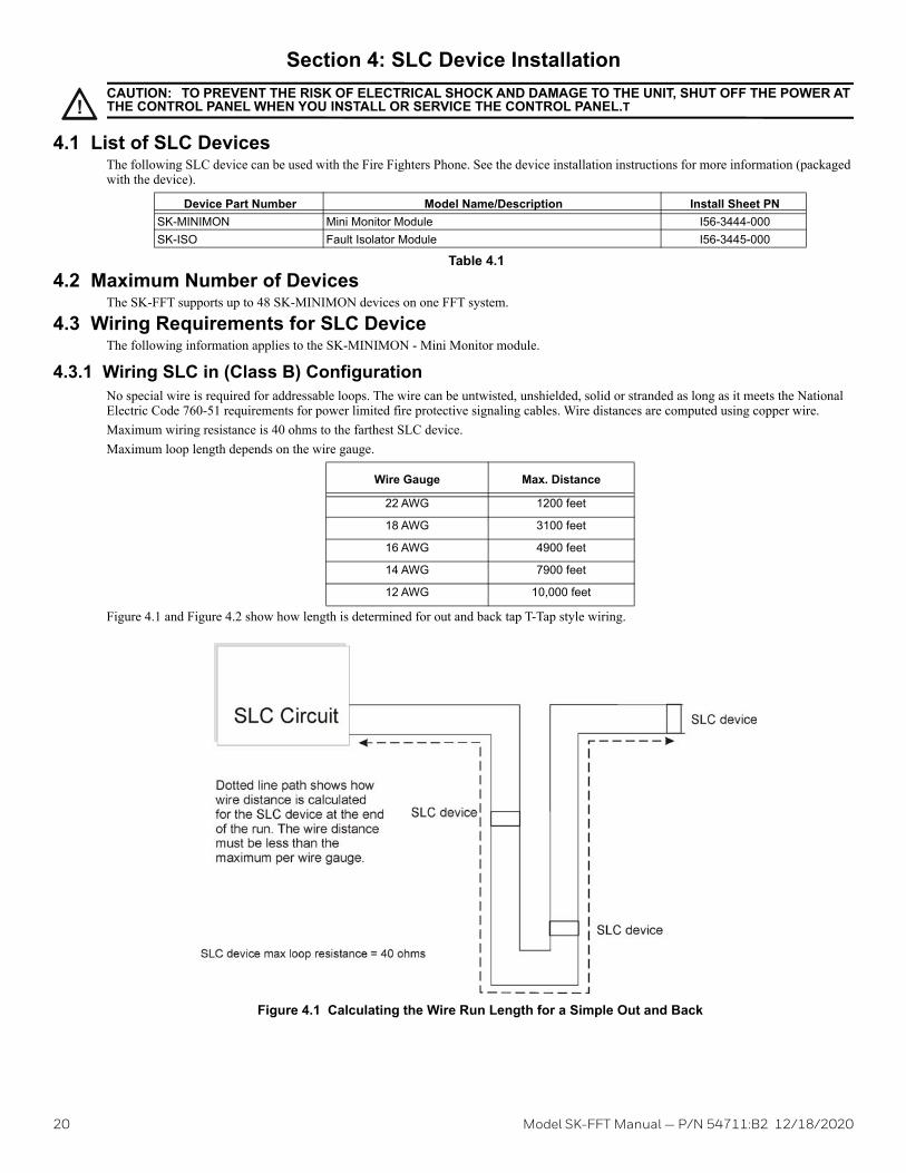
4.1 List of SLC DevicesThe following SLC device can be used with the Fire Fighters Phone. See the device installation instructions for more information (packaged with the device).
4.2 Maximum Number of DevicesThe SK-FFT supports up to 48 SK-MINIMON devices on one FFT system.
4.3 Wiring Requirements for SLC DeviceThe following information applies to the SK-MINIMON - Mini Monitor module.
4.3.1 Wiring SLC in (Class B) ConfigurationNo special wire is required for addressable loops. The wire can be untwisted, unshielded, solid or stranded as long as it meets the National Electric Code 760-51 requirements for power limited fire protective signaling cables. Wire distances are computed using copper wire.Maximum wiring resistance is 40 ohms to the farthest SLC device.Maximum loop length depends on the wire gauge.
Figure 4.1 and Figure 4.2 show how length is determined for out and back tap T-Tap style wiring..
Figure 4.1 Calculating the Wire Run Length for a Simple Out and Back
!CAUTION: TO PREVENT THE RISK OF ELECTRICAL SHOCK AND DAMAGE TO THE UNIT, SHUT OFF THE POWER AT THE CONTROL PANEL WHEN YOU INSTALL OR SERVICE THE CONTROL PANEL.T
Device Part Number Model Name/Description Install Sheet PNSK-MINIMON Mini Monitor Module I56-3444-000SK-ISO Fault Isolator Module I56-3445-000
Table 4.1
Wire Gauge Max. Distance
22 AWG 1200 feet
18 AWG 3100 feet
16 AWG 4900 feet
14 AWG 7900 feet
12 AWG 10,000 feet
20 Model SK-FFT Manual — P/N 54711:B2 12/18/2020

Wiring Requirements for SLC Device SLC Device Installation
When using T-taps, the total length of all taps and the main bus must not exceed 40,000 feet. This requirement must be met in addition to the maximum distance requirements for the various wire gauges.
Figure 4.2 Calculating Wire Run Length for a T-tap
4.3.2 Wiring SLC Devices in (Class A) ConfigurationFigure 4.3 illustrates how to wire the SLC loop for Class A installations. .
Figure 4.3 Class A SLC Configuration
Model SK-FFT Manual — P/N 54711:B2 12/18/2020 21

SLC Device Installation Addressing SK-MINIMON SLC Devices
NOTE 1: Class A does not require the use of isolator modules..
4.4 Addressing SK-MINIMON SLC DevicesAll SK-MINIMON devices are addressed using the two rotary dials that appear on the device board. Use the ONES rotary dial to set the ones place in a one or two digit number, and use the TENS rotary dial to set the tens place in a two digit number. SK-MINIMON modules can be assigned any unique address from 1 to 48. Example 1: To select device address 10, turn the ONES rotary dial to 0 and the TENS rotary dial to 1 as shown in Figure 4.4.Example 2: To select device address 42, turn the ONES rotary dial to 2 and the TENS rotary dial to 4 as show in Figure 4.4.
Figure 4.4 SK-MINIMON SLC Device Addressing using the Rotary Dials
NOTE 2: There are no T-taps allowed on Class A SLC loops.
!CAUTION:For proper system supervision do not use looped wire under terminals marked SLC + and – of the SLC device connectors. Break wire runs to provide supervision of connections.
Example 1: Device set to 10
Example 2: Device Set to 42
22 Model SK-FFT Manual — P/N 54711:B2 12/18/2020

Section 5: Audio Phone Circuit Installation5.1 List of Devices
5.2 Maximum Number of DevicesThe SK-FFT supports up to 48 zones. Each zone consists of one addressable monitor module (SK-MINIMON) and a minimum of one Fire Fighter Telephone Jack (FFT-FPJ).
5.3 Wiring Requirements for the Audio Telephone CircuitThe following information applies to the FFT-FPJ Fire Fighter Phone Jack.
5.3.1 Single Phone Jack Audio Circuit in Class B ConfigurationNo special wire is required for the Audio Telephone Circuit. The wire can be untwisted, unshielded, twisted or shielded as long as it meets the National Electric code 760-51 requirements for power limited fire protective signaling cables.54 Ohm maximum impedance - 12 to 18 AWG.Twisted, shielded wire is recommended for maximum protection against EMI and AFI emissions and susceptibility.If using shielded cable, attach the shield to Grounding Stud below TB6 of the FFT.
Figure 5.1 illustrates single phone jack configuration wiring the audio circuit and SLC for Class B Configuration. Audio circuits must be connected to FFT phone out terminals for all Class B audio configurations.
Figure 5.1 Single Phone Jack Audio Circuit Wired in Class B
Figure 5.2 EOL Example
Part Number DescriptionFFT-FPJ Fire Fighters Telephone Jack
Table 5.1 Devices
NOTE: Do not ground shield on both ends.
Contact EOL Connected(see Figure 5.2 for EOL example)
Caution!For System Supervision-For Terminals 2 and 3, do not use looped wire under the terminals. Break wire run to provide supervision of communications.
4.7K W, 1/2 watt ELR (Install on the last device for Class B telephone circuit only).
PRELIMINARY: Model SK-FFT Manual — P/N 54711:B2 12/18/2020 23

Audio Phone Circuit Installation Wiring Requirements for the Audio Telephone Circuit
5.3.2 Single Phone Jack Audio Circuit Wired in Class A ConfigurationFor information on the wiring specifications, see section 5.3.1. Figure 5.3 illustrates the phone jack audio circuit (Class A) and SLC for (Class A) configuration.
Figure 5.3 Single Phone Jack Audio Circuit in Class A
Contact EOL Connected
24 PRELIMINARY: Model SK-FFT Manual — P/N 54711:B2 12/18/2020

Wiring Requirements for the Audio Telephone Circuit Audio Phone Circuit Installation
5.3.3 Multi-Phone Jack Audio Circuit Wired in Class B ConfigurationFor information on the wiring specifications, see section 5.3.1. Figure 5.4 illustrates how to wire the Multi-Phone Jack audio circuit (Class B) and SLC for (Class B) configuration. In the Multi-Phone Jack configuration, the maximum mini-monitor contact wiring resistance between to first and last FPJ must be less that 100 ohms.
Figure 5.4 Multi-Phone Jack Audio Circuit Wired in Class B
Caution!For System Supervision-For Terminals 2 and 3, do not use looped wire under the terminals. Break wire run to provide supervision of communications.
4.7K W, 1/2 watt ELR (Install on the last device for Class B telephone circuit only).
PRELIMINARY: Model SK-FFT Manual — P/N 54711:B2 12/18/2020 25

Audio Phone Circuit Installation Wiring Requirements for the Audio Telephone Circuit
5.3.4 Multi-Phone Jack Audio Circuit in Class A ConfigurationFor wiring specifications see section 5.3.1. Figure 5.5 illustrates how to wire the Multi-Phone Jack audio circuit (Class A) and SLC for (Class A) configuration. In the Multi-Phone Jack configuration, the maximum Mini-Monitor Contact wiring resistance between the first and last FPJ must be less that 100 ohms..
Figure 5.5 Multi-Phone jack Audio Circuit Wired in Class A5.3.5 Telephone Jack Only Audio Circuit
The FFT can also be configured using only the Fire Fighters Phone Jack (FFT-FPJ). In this configuration, the SK-MINIMON module is not required for system operation. To configure the FFT for Telephone Jack only, the DIP Switch position 1 must be off (SLC Devices not Installed). See Table 3.1.Audio wiring for this configuration is detailed below. See Figure 5.6 and Figure 5.7.
26 PRELIMINARY: Model SK-FFT Manual — P/N 54711:B2 12/18/2020

Wiring Requirements for the Audio Telephone Circuit Audio Phone Circuit Installation
Figure 5.6 Telephone Jack Only Audio Circuit Wired in Class B
Figure 5.7 Telephone Jack Only Audio Circuit Wired in Class A
Caution!For System Supervision-For Terminals 2 and 3, do not use looped wire under the terminals. Break wire run to provide supervision of communications.
4.7K W, 1/2 watt ELR(Install on the last devicefor Class B telephone circuit only).
PRELIMINARY: Model SK-FFT Manual — P/N 54711:B2 12/18/2020 27

Section 6: System OperationThe operation of the SK-FFT Fire Fighter Telephone System allows the audio communication from 24 remote connections through remote handsets from a single local handset. Up to 10 remote handsets can be connected and communicating at one time. The remote audio connec-tions can be expanded to 48 with the optional FFT-24 Zone Expander.
6.1 Key Switch Operations6.1.1 JumpStart Key Switch (on inside of FFT Dead Front Panel).
The JumpStart key will cause the FFT to search the SLC loop for devices. The Active LED (green) will then blink for each zone where a device was found. Press and hold the JumpStart Key for 2 seconds in order to initiate JumpStart.
6.1.2 Accept Key Switch (on inside of FFT dead front panel).The Accept key is used after JumpStart. It will save the current SLC device configuration and re-initialize the FFT. If the user does not press the Accept key within one minute after the JumpStart is complete, its configuration will be discarded and the FFT will be restarted.
6.1.3 Answer Switch When a Remote Handset is connected to one of the FFT-FPJ phone jacks, the Answer LED will blink and the FFT's PZT will sound. Pressing the Answer Switch will connect the local handset to the phone circuit, turn the answer LED on solid, and silence the PZT. Communication between the local and remote handset is now possible. Up to six remote handsets can be connected to the phone circuit simultaneously. After the initial remote handset, the connection of additional handsets does not cause the PZT to sound or the Answer LED to blink.
6.1.4 Silence SwitchThe Silenced Switch is used to silence a system type trouble that has occurred in the FFT system. Once pressed the PZT will silence.
6.2 LED Operations6.2.1 Power Status LED
The Power Status LED is located on the left side of the FFT board. On Power-UP the Power Status LED will blink at a 50% on/off rate until FFT initialization is complete (which takes approximately 20 seconds). Once initialization is complete the Power Status LED will blink at a 10% on and 90% off rate.No key input will be valid until the FFT completes its initialization.
6.2.2 AnswerWhen a Remote Handset connects to the audio channel the Answer LED will blink and the PZT will sound. The operator at the FFT then picks up the local handset and presses the Answer Switch which causes the Answer LED to remain on solid and the PZT goes silent. Com-munication between the local and remote handset is now established. Additional remote handsets can be attached to the audio connection without any intervention at the FFT. Once the last remote handset has disconnected from the FFT, the answer LED will go blank and the sys-tem will be back to normal.
6.2.3 Power The Power LED indicates that 24 VDC is connected to the FFT.
6.2.4 Local Handset TroubleThe local handset trouble LED will activate and blink when there is a problem with the local handset.
6.2.5 Remote Handset TroubleThe remote handset trouble LED will activate and blink when there is a problem with the phone circuit.
6.2.6 General Trouble The General Trouble LED will blink active when system troubles are detected. When the Silence Key is pressed, the General Trouble LED will become constant. Once all system troubles have been restored, the General Trouble LED will deactivate.
6.2.7 Status LEDs (on Inside of FFT dead front panel)LED 1 - SLC Supervision*LED 2 - SLC Extra Point DetectedLED 3 - FFT-24 missingLED 4 - Audio Circuit Supervision
6.2.8 Zone Active Each zone has an Active LED (see Figure 6.1 on page 29). The zone's Active LED will illuminate when a remote handset is plugged into that zone. The LED will turn off when the handset is removed from the zone.
NOTE: * Troubles that will turn LED on: SLC shorted, SLC Class A open trouble and wrong device type.
28 Model SK-FFT Manual — P/N 54711:B2 12/18/2020

JumpStart® Operation System Operation
6.2.9 Zone TroubleEach zone has a Trouble LED (see Figure 6.1). The zone's Trouble LED will blink when specific SLC issues occur such as a missing device or double address. Pressing the Silence Key will cause the zone trouble LED to be on solid. Once the zone trouble is corrected, the LED will turn off.
Figure 6.1 LED Operations6.3 JumpStart® Operation
The JumpStart feature will attempt to locate all SLC Mini-Monitor devices installed in the system, indicate all devices found on the FFT and all FFT-24 Active LED's and allow the user to accept the configuration, repeat the JumpStart or allow the configuration to be discarded.1. To perform the FFT JumpStart press and hold the JumpStart button for 2 seconds. 2. The FFT will search for installed SLC devices and activate the Active LED’s of all zone/point addresses found. 3. When the JumpStart is complete, the first four status LED’s will blink. The user can now press the ACCEPT key causing the FFT to
save the configuration and restart.4. The user presses the JumpStart key again to repeat the SLC search process.5. If the user does not press the Accept key within one minute after the JumpStart is complete, its configuration will be discarded and the
FFT will be restarted.
Answer LED
Active(green)
Trouble(amber)
Model SK-FFT Manual — P/N 54711:B2 12/18/2020 29

30 Model SK-FFT Manual — P/N 54711:B2 12/18/2020
Appendix A: Compatible Powering Devices
A.1 Compatible Power DevicesTable A.1 lists the available Honeywell Silent Knight series compatible power devices used with the SK-FFT.
Model Manual PN5820XL / 5820XL-EVS Addressable Fire Control Panel / Emergency Voice System
151209 / LS10061-001SK-E
5808 Addressable Fire Control Panel 1512745700 Addressable Fire Control Panel 1512955600 25-Point Addressable Fire Control Panel 1514505895XL Power Supply 151142
Table A.1 Compatible Powering Devices

Manufacturer Warranties and Limitation of LiabilityManufacturer Warranties. Subject to the limitations set forth herein, Manufacturerwarrants that the Products manufactured by it in its Northford, Connecticut facilityand sold by it to its authorized Distributors shall be free, under normal use andservice, from defects in material and workmanship for a period of thirty six months(36) months from the date of manufacture (effective Jan. 1, 2009). The Productsmanufactured and sold by Manufacturer are date stamped at the time of production.Manufacturer does not warrant Products that are not manufactured by it in itsNorthford, Connecticut facility but assigns to its Distributor, to the extent possible,any warranty offered by the manufacturer of such product. This warranty shall bevoid if a Product is altered, serviced or repaired by anyone other than Manufactureror its authorized Distributors. This warranty shall also be void if there is a failure tomaintain the Products and the systems in which they operate in proper workingconditions.
MANUFACTURER MAKES NO FURTHER WARRANTIES, AND DISCLAIMS ANYAND ALL OTHER WARRANTIES, EITHER EXPRESSED OR IMPLIED, WITHRESPECT TO THE PRODUCTS, TRADEMARKS, PROGRAMS AND SERVICESRENDERED BY MANUFACTURER INCLUDING WITHOUT LIMITATION,INFRINGEMENT, TITLE, MERCHANTABILITY, OR FITNESS FOR ANYPARTICULAR PURPOSE. MANUFACTURER SHALL NOT BE LIABLE FOR ANYPERSONAL INJURY OR DEATH WHICH MAY ARISE IN THE COURSE OF, OR ASA RESULT OF, PERSONAL, COMMERCIAL OR INDUSTRIAL USES OF ITSPRODUCTS.
This document constitutes the only warranty made by Manufacturer with respect toits products and replaces all previous warranties and is the only warranty made byManufacturer. No increase or alteration, written or verbal, of the obligation of thiswarranty is authorized. Manufacturer does not represent that its products willprevent any loss by fire or otherwise.
Warranty Claims. Manufacturer shall replace or repair, at Manufacturer's discretion,each part returned by its authorized Distributor and acknowledged by Manufacturerto be defective, provided that such part shall have been returned to Manufacturerwith all charges prepaid and the authorized Distributor has completed Manufacturer'sReturn Material Authorization form. The replacement part shall come fromManufacturer's stock and may be new or refurbished. THE FOREGOING ISDISTRIBUTOR'S SOLE AND EXCLUSIVE REMEDY IN THE EVENT OF AWARRANTY CLAIM.
Warn-HL-08-2009.fm
PRELIMINARY: Model SK-FFT Manual — P/N 54711:B2 12/18/2020 31

Honey12 Clin
Northf
203.48
www.s
54711 | B2 | 06-21©2021 Honeywell International Inc.
well Silent Knighttonville Road
ord, CT 06472-1610
4.7161
ilentknight.com