model test of a 5mw floating offshore wind turbine moored ... · a new 5-mw floating offshore wind...
TRANSCRIPT
18th Australasian Fluid Mechanics Conference Launceston, Australia 3-7 December 2012
Model Test of a 5MW Floating Offshore Wind Turbine
Moored by a Spring-tensioned-leg
Pham Thanh Dam
1, Hyunkyoung Shin
*1
*1, 1 School of Naval Architecture and Ocean Engineering, University of Ulsan, Ulsan, South Korea
Abstract
A new 5-MW floating offshore wind turbine moored by a spring-tensioned-leg was proposed for installation in 50m water depth. Its substructure is a platform of the inverted conical cylinder type with massive ballast weight plate at the bottom. A 1:128 scale model was built for the preliminary engineering development. The model tests in regular waves were carried out to estimate motion characteristics of this platform in the wide tank of the University of Ulsan. Its motions were measured respectively and the RAOs were compared. The proposed floating offshore wind
turbine showed a good stability and small amplitude responses in waves, wind and operating conditions of wind turbine.
Key words: Spring-tensioned-leg; floating offshore wind turbine; 5-MW; model test; Response Amplitude Operator.
Acronyms
CB = center of buoyancy CG = center of gravity
FOWT = floating offshore wind turbine MSL = mean sea level RAO = response amplitude operator RNA = rotor nacelle assembly STL = spring tension leg TLP = tension leg platform UOU = University of Ulsan
Introduction
Recently, some floating concepts of offshore wind turbines have been designed and deployed in deep sea greater than 50 meters, while a large number of offshore wind turbines with fixed foundations have been installed in water depths up to 40 meters supporting 3~5 MW RNA.
Several researches on FOWT have been made. Bulder analysed a tri-floater platform wind turbine [1]; Lee studied a 1.5-MW wind turbine [6]; Wayman [9][10], Sclavounos [7], Jonkman [4][5],
Jensen [2] and Wang[8] analysed various TLP, spar, semi-submersible and barge substructures of FOWT.
To produce electricity with higher efficiency at lower costs in deep sea, however, it is necessary to consider building wind farms which are composed with plenty of single FOWTs, not a single FOWT. Then, each a single FOWT should not only have smaller foot prints to reduce and prevent mutual interferences among them, but also have lower installation charges than
existing FOWTs.
In this paper, a new substructure design of FOWT to support a 5-MW RNA [4] for installation in 50 m water depth is suggested while satisfying both smaller foot prints and lower installation
charges. Characteristics of the substructure of FOWT are as
follows:
1. To have a small foot print with quick installation and reduce dynamic tension, a tensioned mooring line with a spring. It also helps to lower total costs of FOWT including installation charges.
2. To ensure that CG is lower than CB in connection with sustaining stability of the FOWT, inverted conical cylinder type with massive ballast weight at its bottom is chosen.
Model scale experiment with a 1/128 scale ratio was carried out in the Ocean Engineering Wide Tank of UOU to study the characteristic of motions of the FOWT platform by obtaining its RAOs and significant motions.
Model test
Floating offshore wind turbine model
The geometric model scale ratio is λ =1: 128 based on Froude
number, time, frequency, velocity and force are derived. Table 1 shows scaling factors for UOU’s model test
Parameter Unit(s) Scale Factor
Length (include wave height …) L λ
Area L2 λ2
Volume L3 λ3
Density M/ L3 1
Mass M λ3
Time T λ0.5
Frequency (rotor rotational speed) 1T-1 λ-0.5
Velocity (wind speed, wave celerity) LT-1 λ0.5
Force (wind, wave) ML/T2 λ3
Mass moment of inertia ML2 λ5
Table 1, Scaling factors for model test of FOWT.
Principal particulars of the floating offshore wind turbine are given in Table 2 and figure 4.
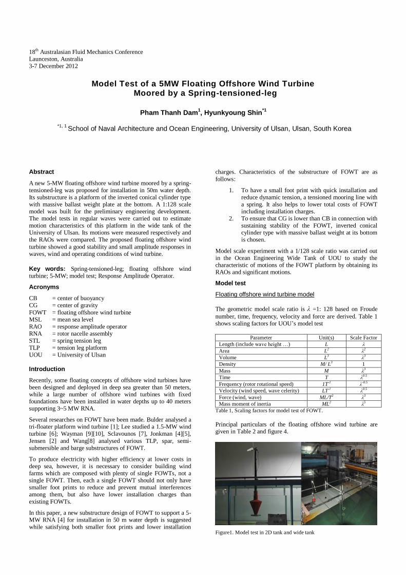
Figure1. Model test in 2D tank and wide tank

Item Full-Scale Model(1:128)
Water Depth 50 m 0.3906 m
Rotor mass 110,000 kg 0.0525 kg
Rotor Diameter 126 m 0.984375 m
Nacelle Mass 240,000 kg 0.1144 kg
Tower Length 77.6 m 0.6063 m
Tower mass 249,718 kg 0.12 kg
Tower Top Diameter 3.87 m 0.0302 m
Tower Base Diameter 6.5 m 0.051 m
Platform Length 45.6 m 0.356m
Platform Top Cylinder Diameter 9.4 m 0.073 m
Platform Top Conical Cylinder 28.67m 0.224m
Platform Weight Plate Diameter 22.53m 0.176m
Platform Mass including Ballast 6,732,000 kg 3.21 kg
Total Structure Mass 7,319000 kg 3.49 kg
Draft with Mooring lines 36.4 m 0.284 m
Center of Buoyancy (from MSL) -16.9m -0.132m
Center of Mass (from MSL) -23.6 m -0.184 m
Roll Inertia of whole system (about MSL) 11.13E9 kgm2 0.324 kgm
2
Pitch Inertia of whole system (about MSL) 11.13E9 kgm2 0.324 kgm
2
Yaw Inertia of whole system (about MSL) 446.7E6 kgm2 0.013 kgm
2
Number of Mooring Lines 1 1
Tensioned Leg Length 13.7 m 0.107 m
Tensioned Leg Diameter 0.128 m 0.001 m
Pretension of Tensioned Leg 9458 KN 4.51 N
Mooring Point (from MSL) -36.35 m -0.284 m
Spring constant 670 KN/m 0.041 N/m
Table 2 Principal particulars of FOWT
The 1:128 scale model was built and installed in 2D tank and wide tank (figure 1). Figure 2 illuminates its detailed drawing with a spring case inside.
Figure 2. FOWT platform of the inverted conical cylinder type.
The model tests were performed in the wide tank which is 30m in
length, 20 m in width, and 2.5 m in height. We use a shallow floor to create the shallow water condition. The model is installed on the floor of wide tank with 18 m in length, 2 m in width and 0.391 m in water depth.
Figure 3. Test set in wide tank.
The model was set at 15 m downstream of the wave generator and a wave probe was placed to measure the wave elevation as shown in figure 3. Four passive makers were mounted on the tower of the model to measure the motions in six degrees of freedom by means of eight VICON cameras (figure 3). Test data
was recorded in 100s with the sampling frequency of 100Hz. Before carrying out the model test, wind speed was measured by 12 anemometers at the position where the model would be installed. A wind generator produces uniform wind up to 10 m/s. Its dimension is 2.0 m in height and 3.5 m in width.
Figure 4. Principal dimensions of model and appendage (unit = mm).
The principal dimensions are shown in figure 4. Four small plates were fastened to the bottom of platform. The material is light plastic.
Load Cases
The model test was carried out in regular waves with wind to obtain the RAO. Wave generator produces 13 regular waves as
shown in Table 3.
Full scale Model test
Period Freq Wave
height Period Freq
Wave
height
(sec) (rad/s) (m) (sec) (rad/s) (m)
7~34 0.90~0.18 2.56 0.62~3.0 10.15~2.09 0.02
Table 3 Model Test Wave Condition (regular wave)
The 5MW wind turbine rotor operates with rotor speed 12.1rpm in 11.4 m/s mean wind speed. Using Froude Number, rotor speed and mean wind speed of model test are determined as hereunder:
Rotor speed of scale model = 136.9 rpm; mean wind speed of scale model = 1.007 m/s. Then 2 load cases are defined as follow: LC1: Regular wave, no wind, parked rotor. LC2: Regular waves, mean wind speed and rotating rotor
Irregular wave
Full scale model Model test (1:128)
No Sea state (s) (m) (s) (m)
1 5 9.7 3.66 0.857 0.029
2 6 11.3 5.49 0.999 0.043
3 7 13.6 9.14 1.202 0.071
4 8 17 15.24 1.503 0.119
Table 4 Irregular waves
Hs - Significant wave height
Tp - Peak-spectral wave period
The model test was also carried out in irregular wave to obtain
the significant responses of the models. ISSC wave spectrum was applied to produce 4 irregular waves as in Table 4. Based on these waves, 2 load cases were defined as follow: LC3: Irregular waves, no wind, parked rotor.
LC4: Irregular waves, mean wind speed, rotating rotor. Results
RAO (Response Amplitude Operator) The motion of FOWT moored by a spring-tensioned-leg (STL) in waves was measured and figure 5 shows the RAOs (surge, heave,
pitch and yaw) of the model in wide tank and in 2D tank respectively.
Heave RAOs were small because of its large diameter of the bottom ballast weight. The surge and pitch motions of the platform of the inverted conical cylinder type were larger in 2D tank. Below 0.3 rad/s surge and pitch RAOs in wide tank tend to reduce but those in 2D tank increase abruptly. The reason may come from channel effect of 2D tank.
The peak frequencies of all modes tend to be smaller than 0.28 rad/s. It shows that FOWT moored by such a STL has a good performance in waves which period is less than 20 s.
There was a very small yaw restoring moment to a spring-tensioned-leg mooring line because of the model’s symmetry in shape. In real condition, it needs to install a torque-matched tensioned leg and/or a yaw controlling device to keep the turbine operating in upwind direction.
Figure 5. RAOs of the inverted conical cylinder with STL in 2D tank and
wide tank in only regular wave,LC1.
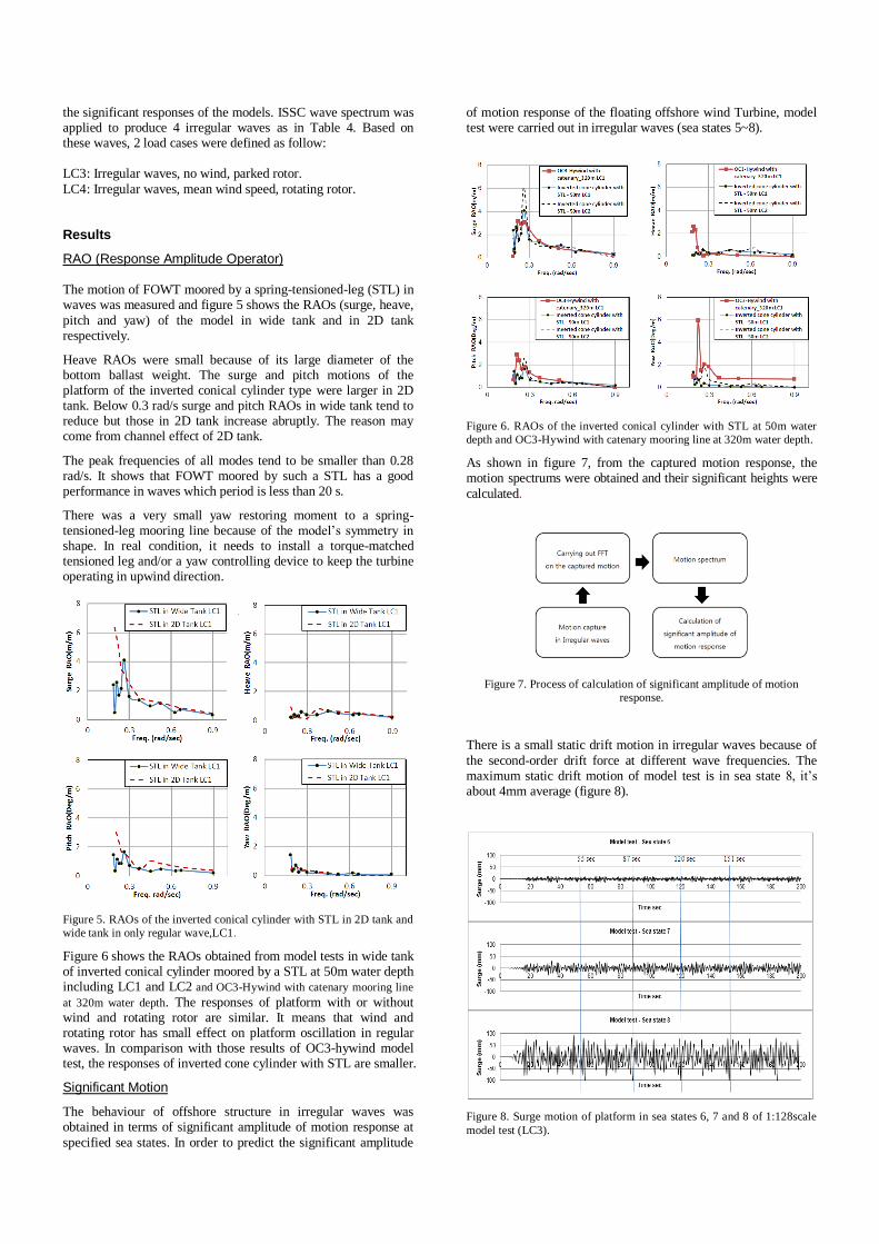
Figure 6 shows the RAOs obtained from model tests in wide tank of inverted conical cylinder moored by a STL at 50m water depth including LC1 and LC2 and OC3-Hywind with catenary mooring line
at 320m water depth. The responses of platform with or without wind and rotating rotor are similar. It means that wind and rotating rotor has small effect on platform oscillation in regular waves. In comparison with those results of OC3-hywind model test, the responses of inverted cone cylinder with STL are smaller.
Significant Motion
The behaviour of offshore structure in irregular waves was obtained in terms of significant amplitude of motion response at
specified sea states. In order to predict the significant amplitude
of motion response of the floating offshore wind Turbine, model test were carried out in irregular waves (sea states 5~8).
Figure 6. RAOs of the inverted conical cylinder with STL at 50m water
depth and OC3-Hywind with catenary mooring line at 320m water depth.
As shown in figure 7, from the captured motion response, the motion spectrums were obtained and their significant heights were
calculated.
Figure 7. Process of calculation of significant amplitude of motion
response.
There is a small static drift motion in irregular waves because of
the second-order drift force at different wave frequencies. The maximum static drift motion of model test is in sea state 8, it’s about 4mm average (figure 8).
Figure 8. Surge motion of platform in sea states 6, 7 and 8 of 1:128scale
model test (LC3).

Time
Static drift motion in mm (average values)
Sea state 6 Sea state 7 Sea state 8
55~58 sec -0.05 -0.294 -4.362
55~120 sec -0.046 -0.32 -3.84
55~151 sec -0.049 -0.34 -3.45
Table 5 Static drift motion of 1:128 scale model in LC3-only irregular
waves
Figure 9 presents significant motions of platform in LC3 and LC4. Surge and pitch significant motions in LC4 are larger than those in LC3 because wind drifts. Heave significant motion in sea states 5 and 6 are similar but heave motion in sea states 7 and 8
are smaller when wind turbine rotating under mean wind speed.
Figure 9. Significant motion height of the inverted conical cylinder
moored by STL at 50m water depth in LC3 and LC4.
Conclusions
A new concept of floating offshore wind turbines (FOWT) of the inverted conical cylinder type moored by a spring-tensioned-leg (STL) was proposed for shallow water application. In order to estimate its motion characteristics, model tests in regular and irregular waves were performed in the wide tank of the
University of Ulsan. To reduce surge and pitch motions in long wave periods, 4 appendage plates were fastened to the platform. The responses of the inverted conical cylinder in wide tank are smaller than those in 2D tank because of channel effect of 2D tank. The ballast weight plate with the large diameter ensured the
proposed FOWT the good stability and small heave motions. Its heave natural frequency of FOWT of the inverted conical cylinder type moored by a STL at 50m water depth remained smaller than 0.18 rad/s.
Effective RAOs of simulation and model test are in good agreement above 0.3 rad/s of wave frequency. Effective RAOs of platform with or without wind and rotating rotor are similar. The proposed floating offshore wind turbine showed a good
stability and small amplitude responses in waves, wind and operating condition of wind turbine.
Acknowledgments
This work was supported by the New & Renewable Energy of the Korea Institute of Energy Technology Evaluation and Planning (KETEP) grant funded by the Korea Government Ministry of Knowledge and Economy. (No. 20114020200050)
References
[1] Bulder, B, van Hees, MTh, Henderson, AR, Huijsmans, RHM, Pierik, JTG, Snijders, EJB,Wijnants, GH, and Wolf, MJ, (2002). “Study to Feasibility of and Boundary Conditions for Floating Offshore Wind Turbines,”ECN,MARIN,TNO,TUD,MSC,Lagerway the Windmaster.
[2] Jensen, JJ, Olsen, AS, and Mansour, AE, (2011). “Extreme Wave and Wind Response Predictions,” Ocean Engineering 38 (2011).
[3] Jonkman, J, (2010). “Definition of the Floating System for Phase IV of OC3,”,National Renewable Energy Laboratory (NREL), Technical Report NREL/TP-500-47535.
[4] Jonkman, J, Butterfield, S, Musial, W, and Scott, G, (2009). “Definition of a 5-MW Reference Wind Turbine for
Offshore System Development,” Technical Report NREL/TP-500-38060.
[5] Jonkman, J, (2009). “Dynamic of Offshore Floating Wind Turbine-Model Development and Verification,” DOI: 10.1002/we.347.
[6] Lee, KH, (2005). “ Responses of Floating Wind Turbines to Wind and Wave Excitation,” MSc Thesis. University of Michigan.
[7] Sclavounos, PD, Tracy, C, and Lee, SH, (2007). “Floating
Offshore Wind Turbines: Responses in a Seastate Pareto Optimal Designs and Economic Assessment,”, Department of Mechanical Engineering, Massachusetts Institute of Technology.
[8] Wang, L, and Sweetman, B, (2012). “ Simulation of large-amplitude Motion of Floating Wind Turbines Using Conservation of Momentum,” Ocean engineering 42 (2012).
[9] Wayman, E, Sclavounos, P, Butterfield, S, Jonkman, J,
Musial, W, (2006). “Coupled Dynamic Modeling of Floating Wind Turbine Systems,” Offshore Technology Conference, Houston, Texas.
[10] Wayman, E, (2006). “Coupled Dynamics and Economic Analysis of Floating Wind Turbine Systems,” M.S. Thesis. MIT.