model: tlm-570, tlm-590, tlm-2-590 refrigerated shaking … · 2019-09-23 · the thermoline tlm...
TRANSCRIPT
OPERATING
INSTRUCTIONS FOR:
MODEL: TLM-570, TLM-590, TLM-2-590 REFRIGERATED SHAKING INCUBATOR
Thermoline Scientific Equipment Pty. Ltd. ABN 80 000 859 129
10-12 Ross Place Wetherill Park NSW 2164. P.O. Box 1851 Wetherill Park DC NSW 1851 Phone: (02) 9604 3911 International: 61 2 9604 3911 Fax: (02) 9725 1706 International: 61 2 9725 1706
Email: [email protected] Web: www.thermoline.com.au
Models TLM-570, TLM-590 & TLM-2-590 Refrigerated Shaking Incubator Manual
26-1-16 2
Introduction: Thank you for selecting this equipment from the large range of products
manufactured & imported by Thermoline Scientific. This manual covers the operation, cleaning, & maintenance instructions for this
equipment. Incorrect operation or use can cause harm or damage to the equipment, therefore it is very important that you read, understand, and implement the instructions, to ensure reliable operation. Please keep this manual in a safe place for future reference.
LIST OF CONTENTS: INTRODUCTION: 2 LIST OF CONTENTS: 2 UNPACKING: 2 USE AND FUNCTION: 2 LOCATION & INSTALLATION:
• Location: • Level: • Mains connection:
3 & 4
OPERATION: • Controls: • Switches: • Changing the temperature: • Setting the speed control: • High Temp Safety:
4 to 10
CLEANING & MAINTAINANCE: 10 & 11 CALIBRATION: 11 to 13 WARRANTY: 13 & 14
UNPACKING: Remove the equipment from the packing material and check for damage. Notify the detail of any damage to your supplier or to Thermoline Scientific without delay. Retain the packing materials until the equipment has been thoroughly tested.
USE & FUNCTION: The Thermoline TLM-570 & TLM-590 refrigerated shaking incubators are upright style incubators with a heavy duty orbital shaking mechanism, that are ideal for laboratory applications where stable and uniform control is required over a wide temperature range.
• Temperatures can be controlled accurately from +5ºC to +70ºC (can be operated at 0ºC for short periods of time without the need for defrost).
• Digital temperature control with set temperature and internal temperature displayed to one decimal place.
• Adjustable shaking speed with duration timer. • Electronic control of heating element for optimum temperature control. • Fan forced air circulation. • Viewing door. • Castors fitted for easy movement. (TLM-590 model only).
Models TLM-570, TLM-590 & TLM-2-590 Refrigerated Shaking Incubator Manual
26-1-16 3
LOCATION & INSTALLATION: Location: All refrigerated equipment generates heat as part of the normal operation. It is vital for correct performance and reliability that adequate ventilation is provided to allow this heat to dissipate.
Any refrigerated equipment that is operated in a small unventilated area, especially in warm weather, can cause the compressor to overheat and may result in premature failure. NOTE: Failure to observe ventilation guidelines will void the manufacturer’s warranty!
You will notice that there are ventilation slots on the sides and/or rear of the base of the incubators. Make sure that none of these vents are blocked to ensure adequate air flow to dissipate heat generated by the refrigeration unit. Level: The incubator should be standing on a firm level surface. The TLM-590 incubator is fitted with castors to allow for easy movement, where the TLM-570 incubator is meant to be mounted on or under a bench and has no castors.
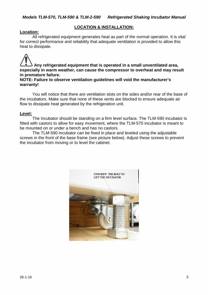
The TLM-590 incubator can be fixed in place and leveled using the adjustable screws in the front of the base frame (see picture below). Adjust these screws to prevent the incubator from moving or to level the cabinet.
Models TLM-570, TLM-590 & TLM-2-590 Refrigerated Shaking Incubator Manual
26-1-16 4
Mains connection: Both models are suitable for connection to a standard 240 volt, 50Hz, supply. A dedicated outlet should be used for the supply, do not use power boards or the like. A 3-pin moulded plug is fitted as standard to the mains lead.
OPERATION: 1: Locate the incubator as previously described, and plug the mains lead into the power supply but do not turn the power on just yet. 2: Attach the shaker tray and adjust the shelf positions to suit your storage needs by moving the shelf clips provided. Controls:
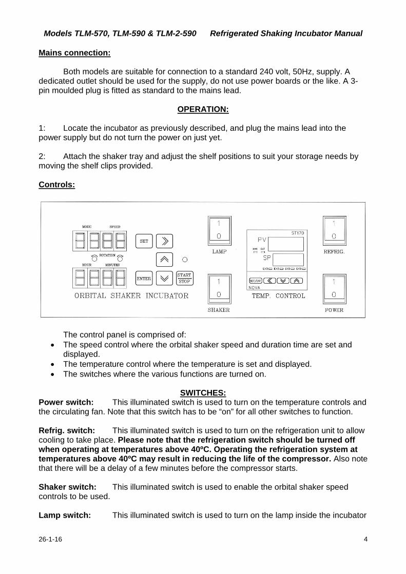
The control panel is comprised of:
• The speed control where the orbital shaker speed and duration time are set and displayed.
• The temperature control where the temperature is set and displayed. • The switches where the various functions are turned on.
SWITCHES:
Power switch: This illuminated switch is used to turn on the temperature controls and the circulating fan. Note that this switch has to be “on” for all other switches to function. Refrig. switch: This illuminated switch is used to turn on the refrigeration unit to allow cooling to take place. Please note that the refrigeration switch should be turned off when operating at temperatures above 40ºC. Operating the refrigeration system at temperatures above 40ºC may result in reducing the life of the compressor. Also note that there will be a delay of a few minutes before the compressor starts. Shaker switch: This illuminated switch is used to enable the orbital shaker speed controls to be used. Lamp switch: This illuminated switch is used to turn on the lamp inside the incubator
Models TLM-570, TLM-590 & TLM-2-590 Refrigerated Shaking Incubator Manual
26-1-16 5
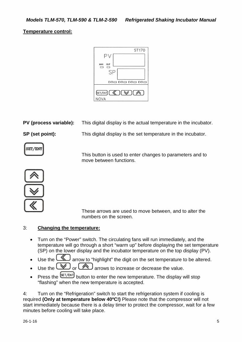
Temperature control:
PV (process variable): This digital display is the actual temperature in the incubator. SP (set point): This digital display is the set temperature in the incubator.
This button is used to enter changes to parameters and to move between functions.
These arrows are used to move between, and to alter the numbers on the screen.
3: Changing the temperature:
• Turn on the “Power” switch. The circulating fans will run immediately, and the temperature will go through a short “warm up” before displaying the set temperature (SP) on the lower display and the incubator temperature on the top display (PV).
• Use the arrow to “highlight” the digit on the set temperature to be altered.
• Use the or arrows to increase or decrease the value.
• Press the button to enter the new temperature. The display will stop “flashing” when the new temperature is accepted.
4: Turn on the “Refrigeration” switch to start the refrigeration system if cooling is required (Only at temperature below 40ºC!) Please note that the compressor will not start immediately because there is a delay timer to protect the compressor, wait for a few minutes before cooling will take place.
Models TLM-570, TLM-590 & TLM-2-590 Refrigerated Shaking Incubator Manual
26-1-16 6
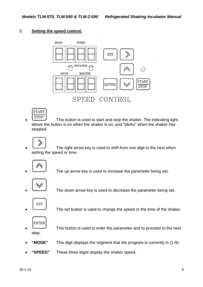
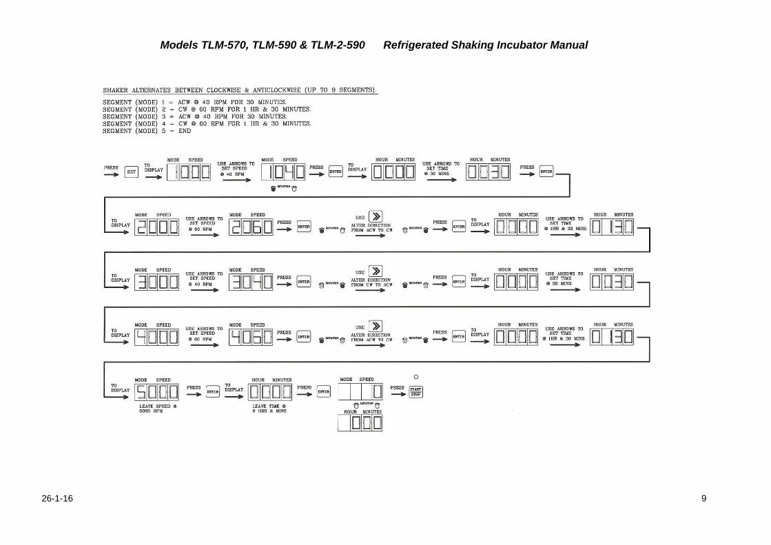
5: Setting the speed control:
• This button is used to start and stop the shaker. The indicating light above the button is on when the shaker is on, and “blinks” when the shaker has stopped.
• The right arrow key is used to shift from one digit to the next when setting the speed or time.
• The up arrow key is used to increase the parameter being set.
• The down arrow key is used to decrease the parameter being set.
• The set button is used to change the speed or the time of the shaker.
• This button is used to enter the parameter and to proceed to the next step.
• “MODE” This digit displays the segment that the program is currently in (1-9).
• “SPEED” These three digits display the shaker speed.
Models TLM-570, TLM-590 & TLM-2-590 Refrigerated Shaking Incubator Manual
26-1-16 7
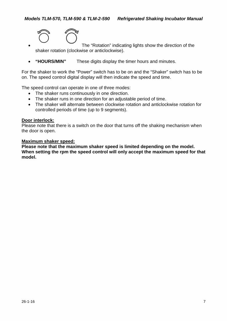
• The “Rotation” indicating lights show the direction of the shaker rotation (clockwise or anticlockwise).
• “HOURS/MIN” These digits display the timer hours and minutes.
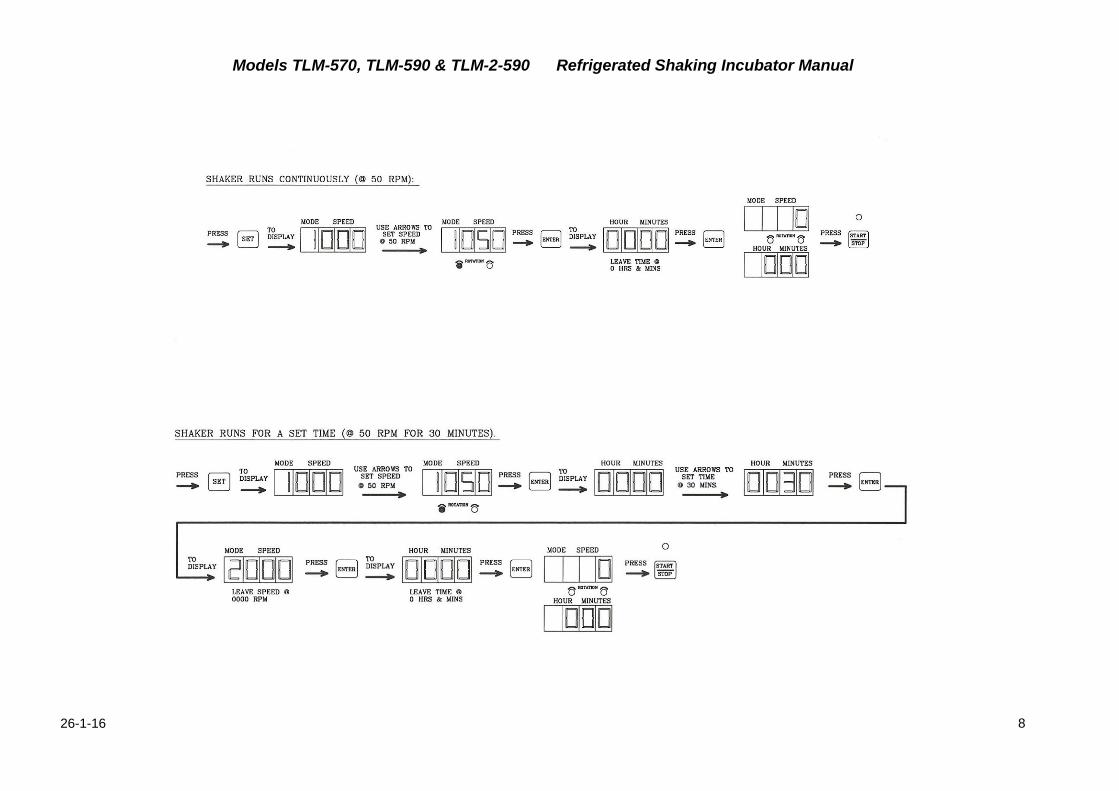
For the shaker to work the “Power” switch has to be on and the “Shaker” switch has to be on. The speed control digital display will then indicate the speed and time. The speed control can operate in one of three modes:
• The shaker runs continuously in one direction. • The shaker runs in one direction for an adjustable period of time. • The shaker will alternate between clockwise rotation and anticlockwise rotation for
controlled periods of time (up to 9 segments). Door interlock: Please note that there is a switch on the door that turns off the shaking mechanism when the door is open. Maximum shaker speed: Please note that the maximum shaker speed is limited depending on the model. When setting the rpm the speed control will only accept the maximum speed for that model.
Models TLM-570, TLM-590 & TLM-2-590 Refrigerated Shaking Incubator Manual
26-1-16 8
Models TLM-570, TLM-590 & TLM-2-590 Refrigerated Shaking Incubator Manual
26-1-16 9
Models TLM-570, TLM-590 & TLM-2-590 Refrigerated Shaking Incubator Manual
26-1-16 10
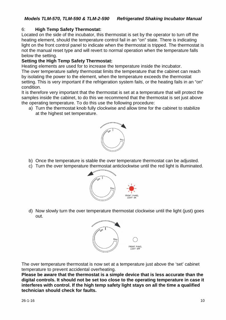
6: High Temp Safety Thermostat: Located on the side of the incubator, this thermostat is set by the operator to turn off the heating element, should the temperature control fail in an “on” state. There is indicating light on the front control panel to indicate when the thermostat is tripped. The thermostat is not the manual reset type and will revert to normal operation when the temperature falls below the setting. Setting the High Temp Safety Thermostat: Heating elements are used for to increase the temperature inside the incubator. The over temperature safety thermostat limits the temperature that the cabinet can reach by isolating the power to the element, when the temperature exceeds the thermostat setting. This is very important if the refrigeration system fails, or the heating fails in an “on” condition. It is therefore very important that the thermostat is set at a temperature that will protect the samples inside the cabinet, to do this we recommend that the thermostat is set just above the operating temperature. To do this use the following procedure:
a) Turn the thermostat knob fully clockwise and allow time for the cabinet to stabilize at the highest set temperature.
b) Once the temperature is stable the over temperature thermostat can be adjusted. c) Turn the over temperature thermostat anticlockwise until the red light is illuminated.
d) Now slowly turn the over temperature thermostat clockwise until the light (just) goes out.
The over temperature thermostat is now set at a temperature just above the ‘set’ cabinet temperature to prevent accidental overheating. Please be aware that the thermostat is a simple device that is less accurate than the digital controls. It should not be set too close to the operating temperature in case it interferes with control. If the high temp safety light stays on all the time a qualified technician should check for faults.
Models TLM-570, TLM-590 & TLM-2-590 Refrigerated Shaking Incubator Manual
26-1-16 11
7: Internal light: The internal light is turned on by using the “Lamp” switch on the control panel.
CLEANING & MAINTENANCE: General cleaning: The interior liner and exterior case can be cleaned using a soft cloth. Never use abrasive cleaners or scouring pads as these will scratch the surface and may result in corrosion. Never use caustic type cleaning agents.
This refrigerated incubator has electrical components such as the temperature control and refrigeration condensing unit. These items should not be subjected to any levels of moisture. For example do not use a hose to wash down the incubator. Evidence of moisture entry into any electrical device will void the manufacturer’s warranty!
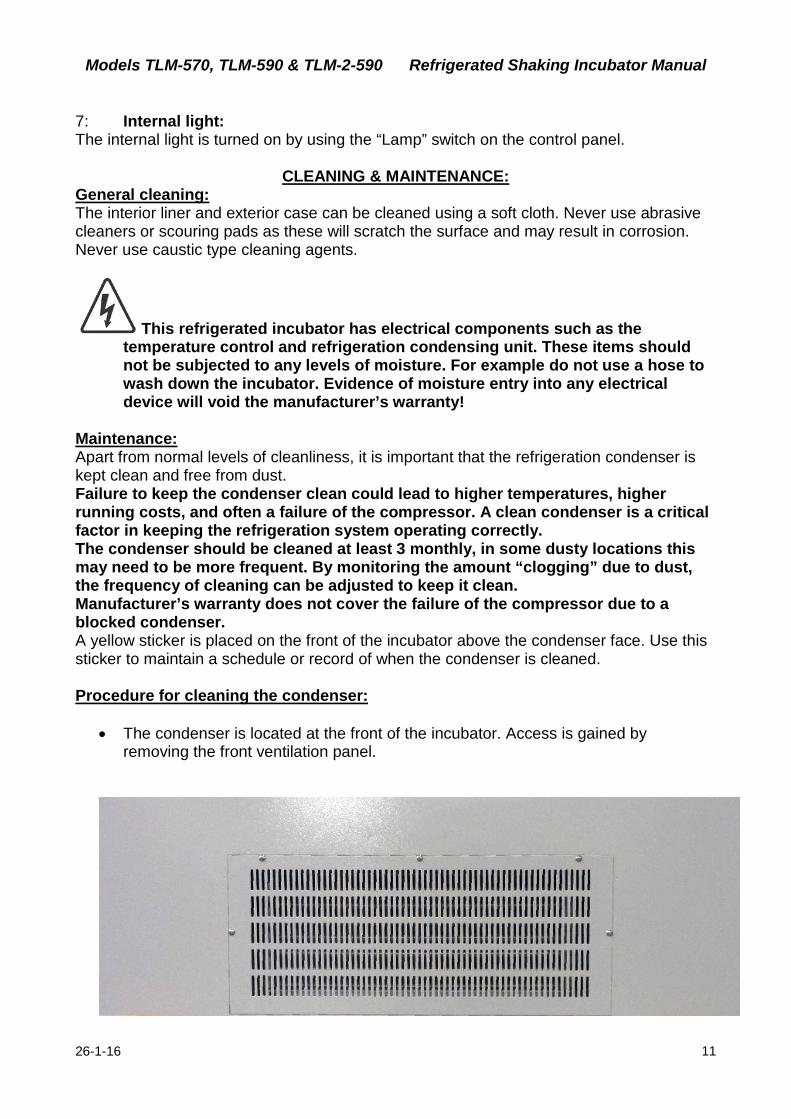
Maintenance: Apart from normal levels of cleanliness, it is important that the refrigeration condenser is kept clean and free from dust. Failure to keep the condenser clean could lead to higher temperatures, higher running costs, and often a failure of the compressor. A clean condenser is a critical factor in keeping the refrigeration system operating correctly. The condenser should be cleaned at least 3 monthly, in some dusty locations this may need to be more frequent. By monitoring the amount “clogging” due to dust, the frequency of cleaning can be adjusted to keep it clean. Manufacturer’s warranty does not cover the failure of the compressor due to a blocked condenser. A yellow sticker is placed on the front of the incubator above the condenser face. Use this sticker to maintain a schedule or record of when the condenser is cleaned. Procedure for cleaning the condenser:
• The condenser is located at the front of the incubator. Access is gained by removing the front ventilation panel.
Models TLM-570, TLM-590 & TLM-2-590 Refrigerated Shaking Incubator Manual
26-1-16 12
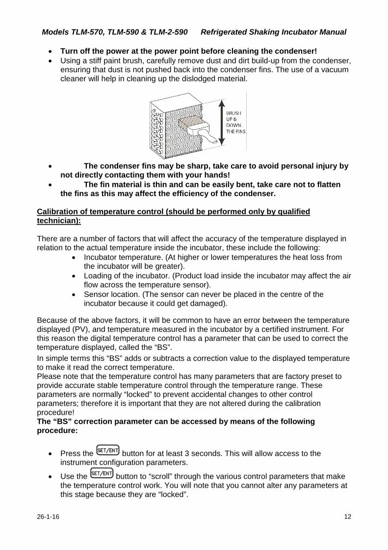
• Turn off the power at the power point before cleaning the condenser! • Using a stiff paint brush, carefully remove dust and dirt build-up from the condenser,
ensuring that dust is not pushed back into the condenser fins. The use of a vacuum cleaner will help in cleaning up the dislodged material.
• The condenser fins may be sharp, take care to avoid personal injury by
not directly contacting them with your hands! • The fin material is thin and can be easily bent, take care not to flatten
the fins as this may affect the efficiency of the condenser. Calibration of temperature control (should be performed only by qualified technician): There are a number of factors that will affect the accuracy of the temperature displayed in relation to the actual temperature inside the incubator, these include the following:
• Incubator temperature. (At higher or lower temperatures the heat loss from the incubator will be greater).
• Loading of the incubator. (Product load inside the incubator may affect the air flow across the temperature sensor).
• Sensor location. (The sensor can never be placed in the centre of the incubator because it could get damaged).
Because of the above factors, it will be common to have an error between the temperature displayed (PV), and temperature measured in the incubator by a certified instrument. For this reason the digital temperature control has a parameter that can be used to correct the temperature displayed, called the “BS”. In simple terms this “BS” adds or subtracts a correction value to the displayed temperature to make it read the correct temperature. Please note that the temperature control has many parameters that are factory preset to provide accurate stable temperature control through the temperature range. These parameters are normally “locked” to prevent accidental changes to other control parameters; therefore it is important that they are not altered during the calibration procedure! The “BS” correction parameter can be accessed by means of the following procedure:
• Press the button for at least 3 seconds. This will allow access to the instrument configuration parameters.
• Use the button to “scroll” through the various control parameters that make the temperature control work. You will note that you cannot alter any parameters at this stage because they are “locked”.
Models TLM-570, TLM-590 & TLM-2-590 Refrigerated Shaking Incubator Manual
26-1-16 13
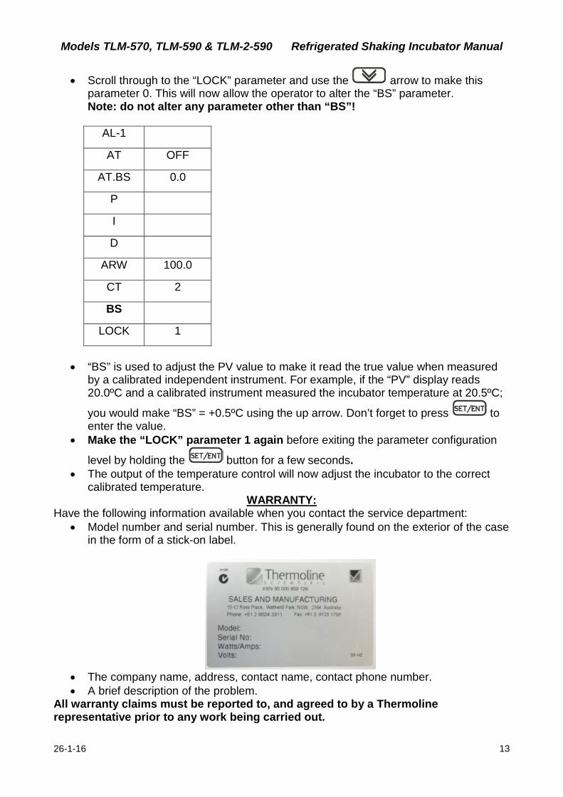
• Scroll through to the “LOCK” parameter and use the arrow to make this parameter 0. This will now allow the operator to alter the “BS” parameter. Note: do not alter any parameter other than “BS”!
AL-1
AT OFF
AT.BS 0.0
P
I
D
ARW 100.0
CT 2
BS
LOCK 1
• “BS” is used to adjust the PV value to make it read the true value when measured
by a calibrated independent instrument. For example, if the “PV” display reads 20.0ºC and a calibrated instrument measured the incubator temperature at 20.5ºC;
you would make “BS” = +0.5ºC using the up arrow. Don’t forget to press to enter the value.
• Make the “LOCK” parameter 1 again before exiting the parameter configuration
level by holding the button for a few seconds. • The output of the temperature control will now adjust the incubator to the correct
calibrated temperature. WARRANTY:
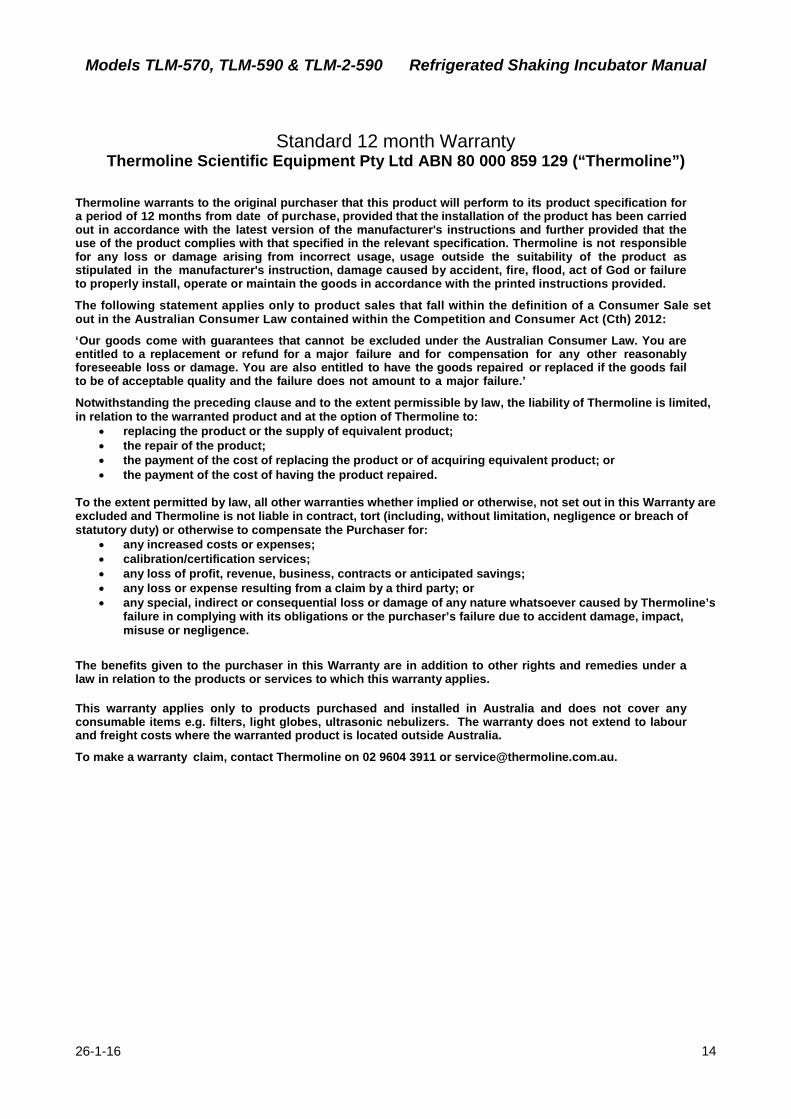
Have the following information available when you contact the service department: • Model number and serial number. This is generally found on the exterior of the case
in the form of a stick-on label.
• The company name, address, contact name, contact phone number. • A brief description of the problem.
All warranty claims must be reported to, and agreed to by a Thermoline representative prior to any work being carried out.
Models TLM-570, TLM-590 & TLM-2-590 Refrigerated Shaking Incubator Manual
26-1-16 14
Standard 12 month Warranty Thermoline Scientific Equipment Pty Ltd ABN 80 000 859 129 (“Thermoline”)
Thermoline warrants to the original purchaser that this product will perform to its product specification for a period of 12 months from date of purchase, provided that the installation of the product has been carried out in accordance with the latest version of the manufacturer's instructions and further provided that the use of the product complies with that specified in the relevant specification. Thermoline is not responsible for any loss or damage arising from incorrect usage, usage outside the suitability of the product as stipulated in the manufacturer's instruction, damage caused by accident, fire, flood, act of God or failure to properly install, operate or maintain the goods in accordance with the printed instructions provided.
The following statement applies only to product sales that fall within the definition of a Consumer Sale set out in the Australian Consumer Law contained within the Competition and Consumer Act (Cth) 2012:
‘Our goods come with guarantees that cannot be excluded under the Australian Consumer Law. You are entitled to a replacement or refund for a major failure and for compensation for any other reasonably foreseeable loss or damage. You are also entitled to have the goods repaired or replaced if the goods fail to be of acceptable quality and the failure does not amount to a major failure.’
Notwithstanding the preceding clause and to the extent permissible by law, the liability of Thermoline is limited, in relation to the warranted product and at the option of Thermoline to:
• replacing the product or the supply of equivalent product; • the repair of the product; • the payment of the cost of replacing the product or of acquiring equivalent product; or • the payment of the cost of having the product repaired.
To the extent permitted by law, all other warranties whether implied or otherwise, not set out in this Warranty are excluded and Thermoline is not liable in contract, tort (including, without limitation, negligence or breach of statutory duty) or otherwise to compensate the Purchaser for:
• any increased costs or expenses; • calibration/certification services; • any loss of profit, revenue, business, contracts or anticipated savings; • any loss or expense resulting from a claim by a third party; or • any special, indirect or consequential loss or damage of any nature whatsoever caused by Thermoline’s
failure in complying with its obligations or the purchaser’s failure due to accident damage, impact, misuse or negligence.
The benefits given to the purchaser in this Warranty are in addition to other rights and remedies under a law in relation to the products or services to which this warranty applies.
This warranty applies only to products purchased and installed in Australia and does not cover any consumable items e.g. filters, light globes, ultrasonic nebulizers. The warranty does not extend to labour and freight costs where the warranted product is located outside Australia.
To make a warranty claim, contact Thermoline on 02 9604 3911 or [email protected].