model trimmer - foster dental · place the model trimmer in a suitable counter top location next to...
TRANSCRIPT

MODEL TRIMMER
MODEL MT10, MT12, and MT15
Operating and Maintenance Instructions
Sales, Service, and Technical Assistance Call Toll Free 800 / 654-4519
Ray Foster Dental Equipment
5421 Commercial Drive Huntington Beach, CA 92649
714 / 897-7795, Fax 714 / 898-6013

INTRODUCTION
Thank you for purchasing a quality Foster product. Your Foster Model Trimmer is designed to give years of trouble free service with minimal care and maintenance. Before putting your new machine to work, please become familiar with this operator's manual to obtain maximum performance and satisfaction.
IMPORTANT SAFTEY INSTRUCTIONS WARNING! When using electrical tools, basic safety precautions should always be followed to reduce the risk of fire, electrical shock, and personal injury including the following: � Read and Save this manual for future reference. � Use Proper Grounding. Your Foster Model Trimmer is equipped with a
three-conductor grounded cord and plug. It should be plugged into a three hole grounded receptacle of the same voltage as inscribed on the machine.
� Power Cord. Power supply, plug configuration, and electrical codes vary from country to country. The cord supplied with your Foster Alloy Grinder is approved for use in the country of destination. Use only this power cord or one that is approved for use in your country.
� Plug into a Branch Circuit with 16A Circuit Breaker. To reduce the risk of
fire and to protect the units electrical system plug into a branch circuit with a 16 amp circuit breaker.
� Disconnect the Power Cord. Before performing any maintenance or repairs
turn the unit off and unplug the power cord to prevent electrical shock or unintentional starting.
� Wear Additional Eye Protection. Protect your eyes from model trimming
debris and the possibility of a fractured wheel by utilizing approved safety glasses or goggles when operating the Foster Model Trimmer.
� Wear Respirator Dust Mask. To protect against the inhalation of dust and
fumes a dust mask should be worn while grinding. � Keep Your Fingers Away From the Grinding Wheel. Use caution when
operating the model trimmer. If the abrasive wheel appears dull, don’t compensate by applying more pressure, change the wheel.
� Always Keep the Door Securely Closed . Be certain that the door is closed
and secured with the door secure knob before turning the machine on. NEVER turn the motor on with the door open.

� Wear Proper Clothing. Do not wear loose clothing or jewelry, which may get caught in rotating parts. Tie back long hair.
� Maintain the Unit. Inspect periodically for damaged or worn parts. Follow
the instructions for maintenance. Don’t use if the power cord, motor, switch, or other parts are in poor condition. Don’t use if the unit has been dropped or damaged. Have a qualified service person inspect and replace parts when necessary.
� For Laboratory Use Only. The Foster Model Trimmer is intended for use by
trained professional laboratory personnel only.
INSTALLATION Place the model trimmer in a suitable counter top location next to a sink and near a water source. Water is supplied to your Foster model trimmer through a flexible polyethylene hose, which is fitted with a 1/4" male pipefitting. If the available water source is other than a 1/4" female pipe fitting, an adapter must be obtained to complete the installation. A local plumbing supply will usually have the required adapter. NOTE: It is recommended that you do NOT use copper tubing to connect the model trimmer to the water supply. The problem with copper tubing is that it is not flexible. This nullifies the feature of the hinged door because the hose must flex when opening the door. Water is discharge from the model trimmer through a 24" x 1” ID flexible hose. Be sure that the hose slopes downward to the drain allowing gravity to drain the model trimmer. Longer lengths of both water supply and drain hose are available from Ray Foster Dental Equipment if needed.
PREVENTIVE MAINTENANCE
FLUSH THE MODEL TRIMMER DAILY Your Foster model trimmer is a workhorse in the dental laboratory. It requires daily flushing and cleaning to prevent gypsum buildup and clogging. At the end of each use allow the motor to remain on and open the water adjustment to maximum for about 20 seconds. Turn the water off and allow the motor to run for an additional 10 seconds. Wipe the exterior of the model trimmer off at the end of each workday.

ELECTRIC MOTOR The motor installed on Foster model trimmers is equipped with permanently lubricated, sealed ball bearings. No lubrication or maintenance is required.
DOOR SECURE When closing and securing the door, do NOT tighten the door secure knob. It is only necessary for the door to "touch" the base casting for a leak free fit. Over tightening may cause leakage.
USE PLENTY OF WATER The use of an adequate amount of water while trimming will keep the wheel clean and cutting. An inadequate volume of water will result in a clogged unusable wheel.
CHECK THE WATER SPRAY TUBE It's a good idea to occasionally check the water spray tube to be sure all holes are open. A straighten paper clip is useful in opening plugged holes.
WATER VALVE The brass water valve located on the door of the model trimmer is intended to be used as a flow control only, and not intended to be used as a water shut-off valve.
MODEL AND SERIAL NUMBER When ordering parts or requesting service always give the machine model number and serial number which are inscribed on the identification plate located on the front of the Lab Master Model Trimmer.
EXCESSIVE VIBRATION
Excess vibration from your model trimmer is a result of one or both of the following: 1. An imbalance in the aluminum back plate as a result of accumulation of
plaster and stone on the back. 2. An out-of-balance abrasive wheel due to stone build-up and/or wear, or an
improperly balanced or non-balanced wheel. NOTE: Abrasive wheels purchase from us are precision balanced for smooth running. This is done by removing a portion of the heavy edge. As a result of the balancing process the wheel may be out-of-round, but is in balance.
To determine and correct an imbalance follow this procedure: 1. Remove the abrasive wheel from the model trimmer, close and secure the
door, and turn the model trimmer on with the wheel removed. If the vibration has ceased, the problem lies with the grinding wheel, and a replacement is needed. NOTE: Sometimes the center mounting devise of the wheel (P/N M095 - Lock Button) is worn and does not center the wheel properly. A wheel that is mounted off center will also cause vibration. To check the Lock Button, remove it together with the wheel, and check it's fit in the center hole of the
wheel. It should slip into the center hole with no play. If it is not a snug fit, it should be replaced.
2. If the vibration is still present with the wheel removed, the problem lies with the aluminum back plate (P/N M222 for MT10, P/N M221 for MT12 and MT15). The backing plate must be removed and cleaned of all plaster, or replaced. To remove the aluminum back plate a Back Plate Removal Tool (item M816) is needed. Please refer to the "Accessories" section of this manual.
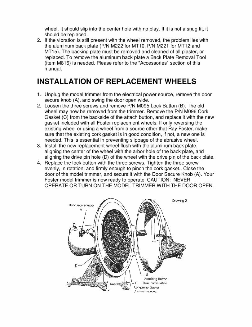
INSTALLATION OF REPLACEMENT WHEELS 1. Unplug the model trimmer from the electrical power source, remove the door
secure knob (A), and swing the door open wide. 2. Loosen the three screws and remove P/N M095 Lock Button (B). The old
wheel may now be removed from the trimmer. Remove the P/N M096 Cork Gasket (C) from the backside of the attach button, and replace it with the new gasket included with all Foster replacement wheels. If only reversing the existing wheel or using a wheel from a source other that Ray Foster, make sure that the existing cork gasket is in good condition, if not, a new one is needed. This is essential in preventing slippage of the abrasive wheel.
3. Install the new replacement wheel flush with the aluminum back plate, aligning the center of the wheel with the arbor hole of the back plate, and aligning the drive pin hole (D) of the wheel with the drive pin of the back plate.
4. Replace the lock button with the three screws. Tighten the three screw evenly, in rotation, and firmly enough to pinch the cork gasket.. Close the door of the model trimmer, and secure it with the Door Secure Knob (A). Your Foster model trimmer is now ready to operate. CAUTION: NEVER OPERATE OR TURN ON THE MODEL TRIMMER WITH THE DOOR OPEN.

ACCESSORIES FOR FOSTER MODEL TRIMMERS
Automatic Solenoid Water Valve – Cat. No. M008 Turns the water on and off automatically and simultaneously with the motor. A great convenience item. Comes complete with illustrated instructions for easy installation. Sediment Tray – Cat. No. M006 Helps keep the counter free of splash and drippings. Handy tray in front for models. Made of sturdy cast aluminum and powder coated to match your Foster model trimmer. Foot Switch – Cat. No. M802 Maintained operation: Push-on / push-off, rated at 10 amps. Orthodontic Work Table Complete – Cat. No. O100 Convert your 12” Foster Model Trimmer to an Orthodontic Model Trimmer capable of trimming accurate and attractive study models. Back Plate Removal Tool – Cat. No. M816 If the Aluminum Back Plate (P/N M221 / M222) must be removed for imbalance corrections, repairs, etc., a Back Plate Removal Tool is essential. Simple illustrated instructions included. Splash Shield – Cat. No. M005 Protect your face and clothing from splatter with an easily installed, fully adjustable splash shield. Diamond Abrasive Wheel Cat. No. D912 – 12” Diameter, Coarse Cat. No. D910 – 10” Diameter, Coarse Coated Abrasive Adhesive Discs Cat. No. A025 – 12” Diameter, Coarse #50 Grit, 4 Pcs Cat. No. A028 – 10” Diameter, Coarse #50 Grit, 6 Pcs Cat. No. A031 -- 12" Diameter X 3/16" Plastic Mounting Wheel Cat. No. A032 -- 10" Diameter X 3/16" Plastic Mounting Wheel

PARTS DIAGRAM

PARTS LIST
REF. PART NUMBER NUMBER DESCRIPTION
1 M009.................................................................................Screw, Switch Box Attach 2 M020........................................................................................Switch Mounting Box 3 M024....................................................................................... Rubber Switch Cover 4 M081.................................................................................................... Motor Switch 5 M138..........................................................................................Electric Power Cord 6 M201...........................................................................Motor Mount Bolt (4 required) 7 M202......................................................................................... Washer (8 required) 8 M203........................................................Rubber Motor Mount Bushing (8 required) 9 M210......................................Base Casting for 10" M.T. (sold as set only with Door) M212……... ............................Base Casting for 12" M.T. (sold as set only with Door) 10 M211......................................................................................................... Hinge Pin 11 M204..............................................................................Nut, Motor Mount Retaining 12 M216...................................................................... Set Screw, Back Plate Retaining 13 M221....................................................................Aluminum Back-Plate for 12" M.T. M222....................................................................Aluminum Back-Plate for 10" M.T. 14 E022 ............................................................... Abrasive Wheel, 12" Medium Coarse E21A ............................................................... Abrasive Wheel, 10" Medium Coarse 15 M097................................................................................... Screw, Wheel Mounting 16 M104KIT .................................................................... Door Gasket, Silicone Rubber 17 M240......................................Door for 12" M.T. (sold as set only with Base Casting) M241......................................Door for 10" M.T. (sold as set only with Base Casting) 18 M018............................................................... Water Spray Tube & Valve Assembly M019............................................................... Water Spray Tube & Valve Assembly 19 M244................................................................................ Plastic Knob, Tray Secure 20 M245................................................................................................. Washer, Nylon 21 M117.............................................................................. Water Supply Hose, 3 Feet 22 M108................................................................................................. Door Lock Bolt 23 M095................................................................... Lock Button with Screws & Gasket 24 M096..........................................................................................Lock Button Gasket 25 M247...................................................................... Standard Work Tray for 10" M.T. M248...................................................................... Standard Work Tray for 12" M.T. 26 M249.......................................................................................................... Drive Pin 27 M255...........................................................................................Rubber Water Seal 28 M257........................................................................................ Cap Nut (4 required) 29 M258................................................................................... Rubber Feet (4 required 30 M259.......................................................... Screw, Front Feet Mounting (2 required) 31 M260...........................................................Screw, Rear Feet Mounting (2 required) 32 M136.................................................................................................Clean Out Plug 33 M263.........................................................................................Adapter, Drain Hose 34 M130...........................................................................................Drain Hose, 2 Feet 35 M109............................................................................... Plastic Knob, Door Secure 36 M100.................................................................................Motor 1/3 HP for 10" M.T. M120.................................................................................Motor 1/2 HP for 12" M.T. M816................................................................................. Back Plate Removal Tool
When ordering replacement parts always include machine model number and serial number as well as individual part number.

Warranty
Ray Foster Dental Equipment warrants Foster Model Trimmers to be free of defects in material and workmanship for a period of one year from the date of purchase by the original user. To obtain warranty service, the Model Trimmer or defective part, together with proof of date of purchase, must be delivered freight prepaid to the factory in Huntington Beach, California. At its option, Ray Foster Dental Equipment Company will replace or repair the defect free of charge, providing the Model Trimmer has not been subjected to abuse, neglect,
damage, or used in a capacity other than which was intended.
Ray Foster Dental Equipment
5421 Commercial Dr, Huntington Beach, CA 92649 714 / 897-7795, Fax 714 / 898-6013