model yk (style e) r-134a cooling only with optiview ...2 york international form 160.54-o2(1102)...
TRANSCRIPT

OPERATING & MAINTENANCE
MAXETM
CENTRIFUGAL LIQUID CHILLERS
Supersedes: NOTHING Form 160.54-O2 (1102)
MODEL YK (STYLE E)R-134a COOLING ONLY
WITH OPTIVIEWTM CONTROL CENTERFOR ELECTRO-MECHANICAL STARTER,
SOLID STATE STARTER & VARIABLE SPEED DRIVE
00611VIP
LDO5842

YORK INTERNATIONAL2
FORM 160.54-O2(1102) FORM 160.54-O2(1102)
3YORK INTERNATIONAL
This equipment is a relatively complicated apparatus. During installation, operation, maintenance or service, individuals may be exposed to certain components or conditions including, but not limited to: refrigerants, oils, materials under pressure, rotating components, and both high and low voltage. Each of these items has the potential, if misused or handled improperly, to cause bodily injury or death. It is the obligation and responsibility of operating/service personnel to identify and recognize these inherent hazards, protect themselves, and proceed safely in completing their tasks. Failure to comply with any of these require-ments could result in serious damage to the equip-ment and the property in which it is situated, as well
IMPORTANT!READ BEFORE PROCEEDING!
GENERAL SAFETY GUIDELINESas severe personal injury or death to themselves and people at the site.
This document is intended for use by owner-authorized operating/service personnel. It is expected that this in-dividual possesses independent training that will enable them to perform their assigned tasks properly and safely. It is essential that, prior to performing any task on this equipment, this individual shall have read and under-stood this document and any referenced materials. This individual shall also be familiar with and comply with all applicable governmental standards and regulations pertaining to the task in question.
SAFETY SYMBOLS
The following symbols are used in this document to alert the reader to areas of potential hazard:
WARNING indicates a potentially hazardous situation which, if not avoided, could result in death or se-rious injury.
DANGER indicates an imminently hazardous situation which, if not avoided, will result in death or serious injury.
CAUTION identifies a hazard which could lead to damage to the machine, damage to other equipment and/or environmental pollution. Usually an instruction will be given, together with a brief explanation.
External wiring, unless specified as an optional connection in the manufacturer’s product line, is NOT to be connected inside the micro panel cabinet. Devices such as relays, switches, transducers and controls may NOT be installed inside the micro panel. NO external wiring is allowed to be run through the micro panel. All wiring must be in accordance with YORK’s published specifications and must be performed ONLY by qualified YORK personnel. YORK will not be responsible for damages/problems resulting from improper connections to the controls or application of improper control signals. Failure to follow this will void the manufacturer’s warranty and cause serious damage to property or injury to persons.
NOTE is used to highlight additional information which may be helpful to you.

YORK INTERNATIONAL2
FORM 160.54-O2(1102) FORM 160.54-O2(1102)
3YORK INTERNATIONAL
CHANGEABILITY OF THIS DOCUMENTIt is the responsibility of operating/service person-nel as to the applicability of these documents to the equipment in question. If there is any question in the mind of operating/service personnel as to the appli-cability of these documents, then, prior to working on the equipment, they should verify with the owner whether the equipment has been modified and if cur-rent literature is available.
DESIGN LEVEL (E)
POWER SUPPLY – for 60 Hz 5 for 50 Hz
COMPRESSOR CODE G4, H0, H1, H2, H3, H4, H5 H6, H8, J1, J2, J3, J4, P1, P2, P3, P4, P5, P6, P7 CONDENSER CODE AB, AC, AD, BB, BC, BD, CR, CG, CH, DF, DG, DH CB, CC, CD, DB, DC, DD, EB, EC, ED, FB, FC, FD, GB, GC, GD, HB, HC, HD, JB, JC, JD, TB, TC, TD, VB, VC, VD EVAPORATOR CODE AB, AC, AD, BB, BC, BD, CR, CG, CH, DF, DG, DH MODEL CB, CC, CD, CE, DB, DC, DD, DE, FB, FC, FD GB, GC, GD, GF, GH, HB, HC, HF, HH, JF, JG JH, TF, TG, TH, VF, VH, WF, WH
NOMENCLATURE YK CB CB G4 – CM E
MOTOR CODE 60 Hz 50 Hz CH CX 5CE 5CT CJ CY 5CF 5CU CK CZ 5CG 5CV CL CA 5CH 5CW CM CB 5CI 5CX CN DA 5CJ 5DA CP DB 5CK 5DB CR DC 5CL 5DC CS DD 5CM 5DD CT DE 5CN 5DE CU DF 5CO 5DF CV DH 5CP 5DG CW DJ 5CQ 5DH CF CG 5CR 5OJ 5CS
In complying with YORK’s policy for continuous product improvement, the information contained in this document is subject to change without notice. While YORK makes no commitment to update or provide current information automatically to the manual owner, that information, if applicable, can be obtained by contacting the nearest YORK Applied Systems Service office.
REFERENCE INSTRUCTIONS DESCRIPTION FORM NO.
SOLID STATE STARTER (MOD “A”) – OPERATION & MAINTENANCE 160.46-OM3.1
SOLID STATE STARTER (MOD “B”) – OPERATION & MAINTENANCE 160.00-O2
VARIABLE SPEED DRIVE – OPERATION 160.00-O1
VARIABLE SPEED DRIVE – SERVICE INSTRUCTIONS 160.00-M1
INSTALLATION 160.54-N1
OPTIVIEW CONTROL CENTER - SERVICE INSTRUCTIONS 160-54-M1
WIRING DIAGRAM – UNIT WITH ELECTRO-MECHANICAL STARTER 160.54-PW1
WIRING DIAGRAM – UNIT WITH MOD “A” SOLID STATE STARTER 160.54-PW2
WIRING DIAGRAM – UNIT WITH MOD “B” SOLID STATE STARTER 160.54-PW2.1
WIRING DIAGRAM – UNIT WITH VARIABLE SPEED DRIVE 160.54-PW3
RENEWAL PARTS – UNIT 160.49-RP4
RENEWAL PARTS – OPTIVIEW CONTROL CENTER 160.54-RP1
WIRING DIAGRAM – UNIT (P Compressors) with ELECTRO-MECHANICAL STARTER 160.54-PW8
WIRING DIAGRAM – UNIT (P Compressors) with MOD “B” SOLID STATE STARTER 160.54-PW9
WIRING DIAGRAM – UNIT (P Compressors) with VARIABLE SPEED DRIVE 160.54-PW10
OPTIVIEW™ PANEL - OPERATION & MAINTENANCE 160.54.O1

YORK INTERNATIONAL4
FORM 160.54-O2(1102) FORM 160.54-O2(1102)
5YORK INTERNATIONAL
SECTION 1 Description of System and Fundamentals of Operation............................... 7
SECTION 2 System Operating Procedures ...................................................................... 9
SECTION 3 System Components Description ............................................................... 15
SECTION 4 Operational Maintenance ........................................................................... 21
SECTION 5 Troubleshooting.......................................................................................... 23
SECTION 6 Maintenance ............................................................................................... 25
SECTION 7 Preventive Maintenance ............................................................................. 34
TABLE OF CONTENTS
YORK INTERNATIONAL4
FORM 160.54-O2(1102) FORM 160.54-O2(1102)
5YORK INTERNATIONAL
LIST OF FIGURES FIG. 1 – MODEL YK MAXETM CHILLER ............................ 7
DETAIL A – COMPRESSOR PREROTATION VANES.................................................................. 8
FIG. 2 – REFRIGERANT FLOW-THROUGH CHILLER..... 9
FIG. 3 – CHILLER STARTING SEQUENCE & SHUTDOWN SEQUENCE (EM STARTER & SOLID STATE STARTER)...... 10
FIG. 4 – CHILLER STARTING SEQUENCE & SHUTDOWN SEQUENCE (VARIABLE SPEED DRIVE)................................11
FIG. 5 – LIQUID CHILLER LOG SHEETS ....................... 12
FIG. 6 – SYSTEM COMPONENTS.................................. 15
FIG. 7 – SCHEMATIC DRAWING (YK) COMPRESSOR LUBRICATION SYSTEM.................................... 16
FIG. 8 – OIL RETURN SYSTEM ...................................... 18
FIG. 9 – CHARGING OIL RESERVOIR WITH OIL .......... 21
FIG. 10 – EVACUATION OF CHILLER .............................. 22
FIG. 11 – SYSTEM PRESSURES...................................... 25
FIG. 12 – SATURATION CURVE ....................................... 27
FIG. 13 – DIAGRAM - MEGGING MOTOR WINDINGS .... 29
FIG. 14 – MOTOR STATOR TEMPERATURE & INSULATION RESISTANCE .............................. 30
YORK INTERNATIONAL6
FORM 160.54-O2(1102) FORM 160.54-O2(1102)
7YORK INTERNATIONAL
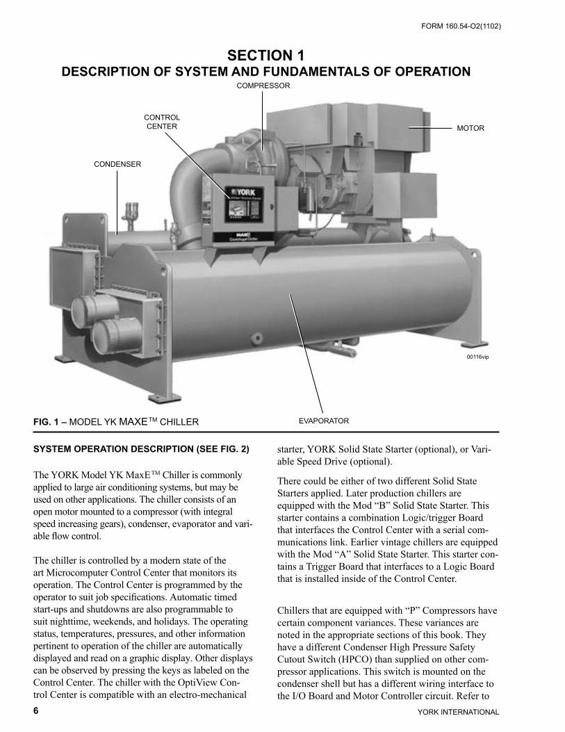
starter, YORK Solid State Starter (optional), or Vari-able Speed Drive (optional).
There could be either of two different Solid State Starters applied. Later production chillers are equipped with the Mod “B” Solid State Starter. This starter contains a combination Logic/trigger Board that interfaces the Control Center with a serial com-munications link. Earlier vintage chillers are equipped with the Mod “A” Solid State Starter. This starter con-tains a Trigger Board that interfaces to a Logic Board that is installed inside of the Control Center.
Chillers that are equipped with “P” Compressors have certain component variances. These variances are noted in the appropriate sections of this book. They have a different Condenser High Pressure Safety Cutout Switch (HPCO) than supplied on other com-pressor applications. This switch is mounted on the condenser shell but has a different wiring interface to the I/O Board and Motor Controller circuit. Refer to
SECTION 1DESCRIPTION OF SYSTEM AND FUNDAMENTALS OF OPERATION
00116vip
CONDENSER
CONTROLCENTER
COMPRESSOR
MOTOR
EVAPORATORFIG. 1 – MODEL YK MAXETM CHILLER
SYSTEM OPERATION DESCRIPTION (SEE FIG. 2)
The YORK Model YK MaxETM Chiller is commonly applied to large air conditioning systems, but may be used on other applications. The chiller consists of an open motor mounted to a compressor (with integral speed increasing gears), condenser, evaporator and vari-able flow control.
The chiller is controlled by a modern state of the art Microcomputer Control Center that monitors its operation. The Control Center is programmed by the operator to suit job specifications. Automatic timed start-ups and shutdowns are also programmable to suit nighttime, weekends, and holidays. The operating status, temperatures, pressures, and other information pertinent to operation of the chiller are automatically displayed and read on a graphic display. Other displays can be observed by pressing the keys as labeled on the Control Center. The chiller with the OptiView Con-trol Center is compatible with an electro-mechanical

YORK INTERNATIONAL6
FORM 160.54-O2(1102) FORM 160.54-O2(1102)
7YORK INTERNATIONAL
1
the I/O Board section of this book. Also, “P” com-pressor applications are equipped with a High Speed Thrust Bearing Limit Switch instead of the Proximity Probe supplied on other compressors. This device de-tects abnormal bearing position through probe contact instead of distance measurement as performed with the Proximity Probe.
In operation, a liquid (water or brine to be chilled) flows through the evaporator, where boiling refriger-ant absorbs heat from the liquid. The chilled liquid is then piped to fan coil units or other air conditioning terminal units, where it flows through finned coils, absorbing heat from the air. The warmed liquid is then returned to the chiller to complete the chilled liquid circuit.
7619A(D)
DETAIL A – COMPRESSOR PREROTATION VANES
Description of System and Fundamentals of Operation
The refrigerant vapor, which is produced by the boil-ing action in the evaporator, flows to the compressor where the rotating impeller increases its pressure and temperature and discharges it into the condenser. Wa-ter flowing through the condenser tubes absorbs heat from the refrigerant vapor, causing it to condense. The condenser water is supplied to the chiller from an ex-ternal source, usually a cooling tower. The condensed refrigerant drains from the condenser into the liquid return line, where the variable orifice meters the flow of liquid refrigerant to the evaporator to complete the refrigerant circuit.
The major components of a chiller are selected to handle the refrigerant, which would be evaporated at full load design conditions. However, most systems will be called upon to deliver full load capacity for only a relatively small part of the time the unit is in operation.
CAPACITY CONTROLThe major components of a chiller are selected for full load capacities, therefore capacity must be controlled to maintain a constant chilled liquid temperature leav-ing the evaporator. Prerotation vanes (PRV), located at the entrance to the compressor impeller, compensate for variation in load (See Detail A).
The position of these vanes is automatically con-trolled through a lever arm attached to an electric motor located outside the compressor housing. The automatic adjustment of the vane position in effect provides the performance of many different compres-sors to match various load conditions from full load with vanes wide open to minimum load with vanes completely closed.

YORK INTERNATIONAL8
FORM 160.54-O2(1102) FORM 160.54-O2(1102)
9YORK INTERNATIONAL
FIG. 2 – REFRIGERANT FLOW-THRU CHILLER
PREROTATION VANES(See Detail A)
SUCTION
EVAPORATOR
ELIMINATOR
OIL COOLER
LD00924
FLOW CONTROLORIFICE
SUB-COOLER
CONDENSER
DISCHARGEBAFFLE
DISCHARGE
COMPRESSOR
YORK INTERNATIONAL8
FORM 160.54-O2(1102) FORM 160.54-O2(1102)
9YORK INTERNATIONAL
SECTION 2SYSTEM OPERATING PROCEDURES
OIL HEATERS
If the oil heater is de-energized during a shutdown pe-riod, it must be energized for 12 hours prior to starting compressor, or remove all oil and recharge compressor with new oil. (See “Oil Charging Procedure”, page 22.)
OIL HEATER OPERATION
The oil heater operation is controlled by the OptiView™ Control Center. The heater is turned on and off to maintain the oil temperature to a value 50°F (10°C) above the condenser saturation tempera-ture. This is the target value and if the oil temperature falls to 4°F (-15.5°C) or more below the target, the heater is turned on. It is turned off when the oil temperature increases to 3°F (-16°C) above the target value.
If the target value is greater than 160°F (71°C), the target defaults to 160°F (71°C). If the target value
is less than 110°F (43.3°C), it defaults to 110°F (43.3°C).To prevent overheating of the oil in the event of a control center component failure, the oil heater ther-mostat (1HTR) is set to open at 180°F (82°C).
CHECKING THE OIL LEVEL IN THE OIL RESERVOIR
Proper operating oil level – the upper and lower sight glasses.If the oil is excessively high after start-up, the excess oil may be drained from the oil filter drain valve while the compressor is running.If oil level is low, oil should be added to the com-pressor. (See “Oil Charging Procedure”, page 22)
Comply with EPA and Local regu-lations when removing or dispos-ing of Refrigeration System oil!
START-UP PROCEDURE
Pre-StartingPrior to starting the chiller, observe the OptiView Control Center. Make sure the display reads SYS-TEM READY TO START.
To pre-start the chiller, use the following procedure:
1. Oil Heater – The oil heater must be energized for 12 hours prior to starting the chiller.
2. Prior to start, the clock must be programmed for the proper day and time. Any setpoints which are desired to be changed may be programmed. All Control Center setpoints should be programmed before the chiller is started. (Refer to Form 160.54-O1).
Vent ant air from the chiller water boxes prior to starting the water pumps. Failure to do so will result in pass baffle damage.
START-UP
1. If the chilled water pump is manually operated, start the pump. The Control Center will not allow the chiller to start unless chilled liquid flow is es-tablished through the unit. (A field supplied chilled water flow switch is required.) If the chilled liquid pump is wired to the Microcomputer Control Cen-ter the pump will automatically start, therefore, this step is not necessary.
System Operating Procedures
YORK INTERNATIONAL10
FORM 160.54-O2(1102) FORM 160.54-O2(1102)
11YORK INTERNATIONAL
2. To start the chiller, press the COMPRESSOR START switch. This switch will automatically spring return to the RUN position. (If the unit was previously started, press the STOP/RESET side of the COMPRESSOR switch and then press the START side of the switch to start the chiller.) When the start switch is energized, the Control Center is placed in an operating mode and any malfunction will be noted by messages on a graphic display.
Any malfunctions which occur dur-ing STOP/RESET are also displayed.
When the chiller is shut down, the prerotation vanes will close automatically to prevent loading the com-pressor on start-up.
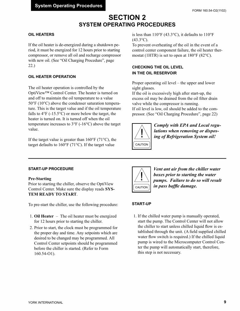
When the chiller starts to operate, the following au-tomatic sequences are initiated: (Refer to Fig. 3 & 4, “Chiller Starting & Shutdown Sequence Chart”.) 1. The OptiView Control Center display message
will read SYSTEM PRELUBE for the first 50 seconds of the starting sequence.
2. The oil pump will start to circulate oil for a 50 second pre-run to establish oil flow and adequate lubrication to all bearings, gears, and rotating sur-faces within the compressor.
The high and low oil pressure transducers (OP) and the oil temperature sensor (RT3) will sense any malfunction in the lubrication system.
3. The anti-recycle timer software function will op-erate after the 50 seconds of pre-run time. At this time, the timer will be initiated and will run for 30 minutes after the compressor starts. If the chiller shuts down during this period of time, it cannot be started until the timer completes the 30 minute cycle.
4. The chilled liquid pump contacts will close, start-ing the chilled liquid pump, to allow liquid flow through the evaporator when the COMPRESSOR start switch is energized.
5. After the first 50 seconds of operation, the com-pressor will start.
6. For display messages and information pertaining to the operation of the OptiView™ Control Center, refer to Form 160.54-O1.
FIG. 3 – CHILLER STARTING SEQUENCE & SHUTDOWN SEQUENCE (EM STARTER & SOLID STATE STARTER)
LD04040
** NOT FOR ALL SHUTDOWNS. REFER TO “DISPLAY MES-SAGES” SECTION OF THIS MANUAL.

YORK INTERNATIONAL10
FORM 160.54-O2(1102) FORM 160.54-O2(1102)
11YORK INTERNATIONAL
2
FIG. 4 – CHILLER STARTING SEQUENCE & SHUTDOWN SEQUENCE (VARIABLE SPEED DRIVE)
LD04130
CHILLER OPERATION
After the compressor reaches its operating speed, the Prerotation Vanes will begin to open under the control of the Microprocessor Board which senses the leav-ing chilled liquid temperature. The unit capacity will vary to maintain the leaving CHILLED LIQUID TEMPERATURE setpoint. The Prerotation Vanes are modulated by an actuator under the control of the Microprocessor Board. The vane control routine employs proportional plus derivative (rate) control action. A drop in chilled liquid temperature will cause the actuator to close the Prerotation Vanes to decrease chiller capacity. When the chilled liquid temperature rises, the actuator will open the Prerotation Vanes to increase the capacity of the chiller.
However, the current draw (amperes) by the com-pressor motor cannot exceed the setting of the % CURRENT LIMIT at any time during the unit operation, since the Microcomputer Control Center 40 to 100% three-phase peak current limit software function, plus the 3-phase 100% solid state overload current limiter (CM-2), on Electro-Mechanical Starter applications, or the Solid State Starter current Limit function will override the temperature control func-tion and prevent the Prerotation Vanes from opening beyond the % CURRENT LIMIT setting.
** NOT FOR ALL SHUTDOWNS. REFER TO “DISPLAY MES-SAGES” SECTION OF THIS MANUAL.
System Operating Procedures
If the load continues to decrease, after the Prerotation Vanes are entirely closed, the chiller will be shut down by the Leaving Chilled Liquid – Low Temperature Control.
CONDENSER WATER TEMPERATURE CONTROL
The YORK MaxETM chiller is designed to use less power by taking advantage of lower than design temperatures that are naturally produced by cooling towers throughout the operating year. Exact control of condenser water such as a cooling tower bypass, is not necessary for most installations. The chiller requires only that the minimum condenser water temperature be no lower than the value determined by referring to the formula below:
where:
Min. ECWT = LCWT – C RANGE + 17ºFMin. ECWT = LCWT – C RANGE + 9.4ºC
ECWT = Entering Condensing Water Temperature LCWT = Leaving Chilled Water TemperatureC Range = Condensing water temperature range at the given load condition.
YORK INTERNATIONAL12
FORM 160.54-O2(1102) FORM 160.54-O2(1102)
13YORK INTERNATIONAL
OPERATING INSPECTIONS – See Section 2
By following a regular inspection using the display readings of the Microcomputer Control Center, and maintenance procedure, the operator will avoid seri-ous operating difficulty. The following list of inspec-tions and procedures should be used as a guide.
Daily
1. Check OptiView™ Control Center displays. 2. If the compressor is in operation, check the bear-
ing oil pressure on the SYSTEM Screen. Also check the oil level in the oil reservoir. Operating oil level should be between the upper and lower sight glasses. Drain or add oil if necessary.
3. Check entering and leaving condenser water pres-sure and temperatures for comparison with job design conditions. Condenser water temperatures can be checked on the SYSTEM Screen.
4. Check the entering and leaving chilled liquid tem-peratures and evaporator pressure for comparison with job design conditions on the SYSTEM Screen.
5. Check the condenser saturation temperature (based upon condenser pressure sensed by the condenser transducer) on the SYSTEM Screen.
6. Check the compressor discharge temperature on the SYSTEM Screen. During normal operation discharge temperature should not exceed 220°F (104°C).
At start-up, the entering condenser water tempera-ture may be as much as 25°F (14°C) colder than the standby return chilled water temperature. Cooling tower fan cycling will normally provide adequate control of the entering condenser water temperature on most installations.
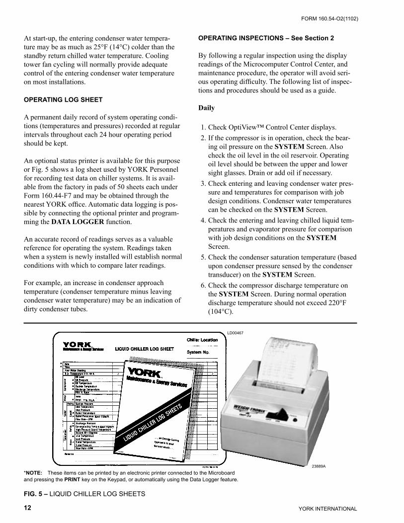
OPERATING LOG SHEET
A permanent daily record of system operating condi-tions (temperatures and pressures) recorded at regular intervals throughout each 24 hour operating period should be kept.
An optional status printer is available for this purpose or Fig. 5 shows a log sheet used by YORK Personnel for recording test data on chiller systems. It is avail-able from the factory in pads of 50 sheets each under Form 160.44-F7 and may be obtained through the nearest YORK office. Automatic data logging is pos-sible by connecting the optional printer and program-ming the DATA LOGGER function.
An accurate record of readings serves as a valuable reference for operating the system. Readings taken when a system is newly installed will establish normal conditions with which to compare later readings.
For example, an increase in condenser approach temperature (condenser temperature minus leaving condenser water temperature) may be an indication of dirty condenser tubes.
FIG. 5 – LIQUID CHILLER LOG SHEETS
*NOTE: These items can be printed by an electronic printer connected to the Microboard and pressing the PRINT key on the Keypad, or automatically using the Data Logger feature.
LD00467
23889A
YORK INTERNATIONAL12
FORM 160.54-O2(1102) FORM 160.54-O2(1102)
13YORK INTERNATIONAL
2
7. Check the compressor motor current on the SYSTEM Screen.
8. Check for any signs of dirty or fouled condenser tubes. (The temperature difference between water leaving condenser and saturated condensing tem-perature should not exceed the difference recorded for a new unit by more than 4°F, 2.2°C).
Weekly
1. Check the refrigerant charge. (See “Checking The Refrigerant Charge”,page 28.)
2. Leak check the entire chiller.
Quarterly
1. Perform chemical analysis of oil.
Semi-Annually (or more often as required)
1. Change and inspect compressor oil filter element.
2. Oil return system.
a. Change dehydrator.
b. Check nozzle of eductor for foreign particles.
3. Check controls and safety cutouts.
Annually (more often if necessary)
If quarterly inspection indicates oil is fine, replacing the oil is not necessary.
1.Drain and replace the oil in the compressor oil sump. (See “Oil Charging Procedure” page 22.)
2. Evaporator and Condenser.
a. Inspect and clean water strainers.
b. Inspect and clean tubes as required.
c. Inspect end sheets.
3. Compressor Drive Motor (See motor manufacturers maintenance and service instruction supplied with unit)
a. Clean air passages and windings per manufac-turers instructions.
b. Meg motor windings – See Fig. 13 for details.
c. Lubricate per motor manufacturer recommenda-tions.
4. Inspect and service electrical components as necessary.
5. Perform refrigerant analysis.
NEED FOR MAINTENANCE OR SERVICE
If the system is malfunctioning in any manner or the unit is stopped by one of the safety controls, consult the “Operation Analysis Chart”, (Table 1), pages 23 and 24 of this instruction. After consulting this chart, if you are unable to make the proper repairs or adjust-ments to start the compressor or the particular trouble continues to hinder the performance of the unit, please call the nearest YORK District Office. Failure to report constant troubles could damage the unit and increase the cost of repairs.
STOPPING THE SYSTEM
The Optiview™ Control Center can be programmed to start and stop automatically (maximum, once each day) whenever desired. Refer to Form 160.54-O1. To stop the chiller, proceed as follows:
1. Push the COMPRESSOR STOP/RESET switch. The compressor will stop automatically. The oil pump will continue to run for coastdown period. The oil pump will then stop automatically.
2. Stop the chilled water pump (if not wired into the Microcomputer Control Center, in which case it will shut off automatically simultaneously with the oil pump.) (The actual water pump contact opera-tion is dependent upon the position of Microboard jumper J54.)
3. Open the switch to the cooling tower fan motors, if used.
4. The compressor sump oil heater is energized when the unit is stopped.
PROLONGED SHUTDOWN
If the chiller is to be shut down for an extended period of time (for example, over the winter season), the following paragraphs outline the procedure to be fol-lowed.
System Operating Procedures
YORK INTERNATIONAL14
FORM 160.54-O2(1102) FORM 160.54-O2(1102)
15YORK INTERNATIONAL
1. Test all system joints for refrigerant leaks with a leak detector. If any leaks are found, they should be repaired before allowing the system to stand for a long period of time.
During long idle periods, the tightness of the sys-tem should be checked periodically.
2. If freezing temperatures are encountered while the system is idle, carefully drain the cooling water from the cooling tower, condenser, condenser pump, and the chilled water system-chilled water pump and coils.
Open the drains on the evaporator and condenser liquid heads to assure complete drainage. (If a Variable Speed Drive, drain its water cooling sys-tem. If Solid State Starter. drain water from starter cooling loop.)
3. On the SETUP Screen, disable the clock. This conserves the battery.
4. Open the main disconnect switches to the com-pressor motor, condenser water pump and the chilled water pump. Open the 115 volt circuit to the Control Center.
YORK INTERNATIONAL14
FORM 160.54-O2(1102) FORM 160.54-O2(1102)
15YORK INTERNATIONAL
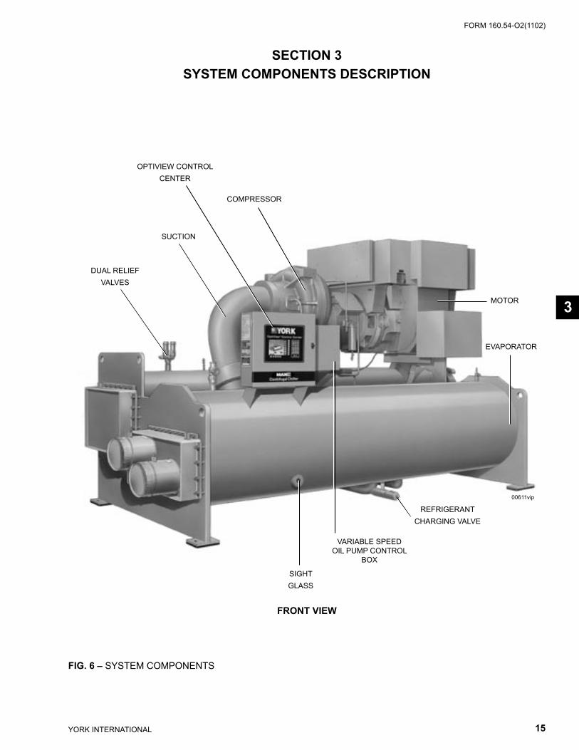
SECTION 3SYSTEM COMPONENTS DESCRIPTION
MOTOR
EVAPORATOR
COMPRESSOR
SUCTION
DUAL RELIEFVALVES
SIGHTGLASS
VARIABLE SPEED OIL PUMP CONTROL
BOX
REFRIGERANTCHARGING VALVE
00611vip
FRONT VIEW
FIG. 6 – SYSTEM COMPONENTS
OPTIVIEW CONTROLCENTER
3
YORK INTERNATIONAL16
FORM 160.54-O2(1102) FORM 160.54-O2(1102)
17YORK INTERNATIONAL
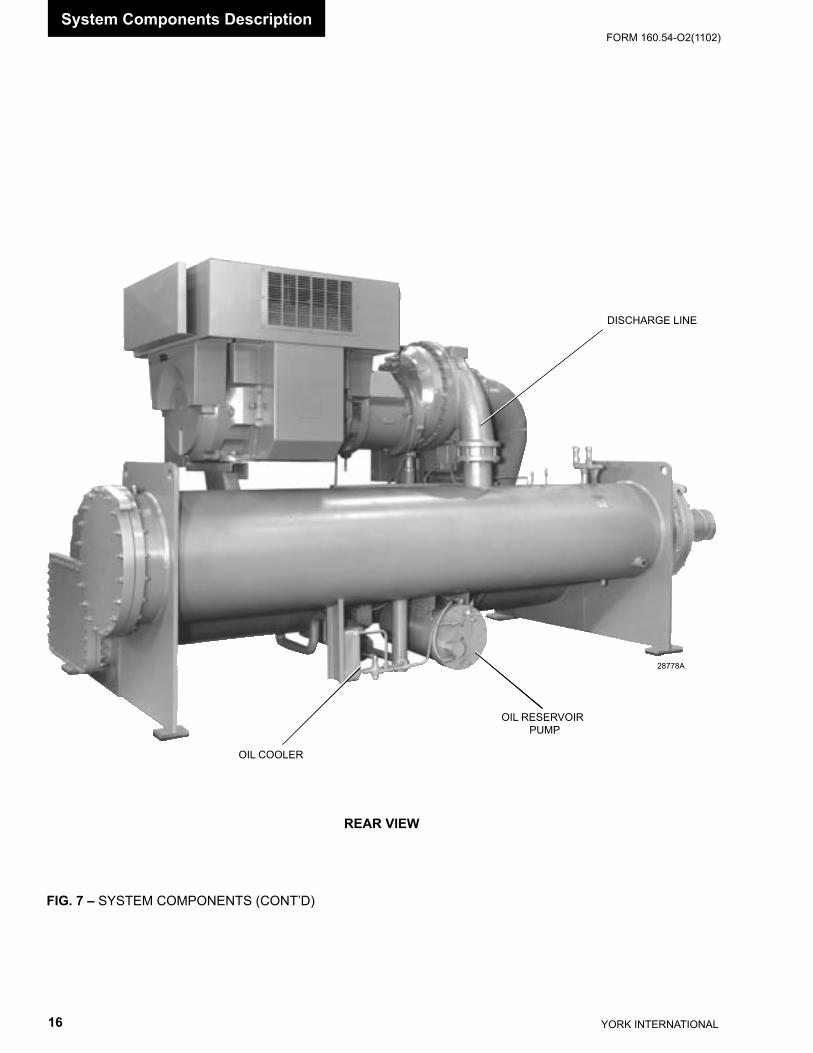
FIG. 7 – SYSTEM COMPONENTS (CONT’D)
28778A
DISCHARGE LINE
OIL COOLER
OIL RESERVOIR PUMP
REAR VIEW
System Components Description
YORK INTERNATIONAL16
FORM 160.54-O2(1102) FORM 160.54-O2(1102)
17YORK INTERNATIONAL
GENERAL
The YORK Model YK MaxETM Centrifugal Liquid Chiller is completely factory-packaged including evapo-rator, condenser, compressor, motor, lubrication system, OptiView Control Center, and all interconnecting unit piping and wiring.
COMPRESSOR
The compressor is a single-stage centrifugal type pow-ered by an open-drive electric motor.
The rotor assembly consists of a heat-treated alloy steel drive shaft and impeller shaft with a cast aluminum, fully shrouded impeller. The impeller is designed for balanced thrust and is dynamically balanced and over-speed tested. The inserted type journal and thrust bear-ings are fabricated of aluminum alloy. Single helical gears with crowned teeth are designed so that more than one tooth is in contact at all times. Gears are integrally assembled in the compressor rotor support and are film lubricated. Each gear is individually mounted in its own journal and thrust bearings.
The open-drive compressor shaft seal is a double bellows cartridge style with ceramic internal and atmospheric seal faces. The seal is oil-flooded at all times and is pressure-lubricated during operation.
CAPACITY CONTROL
Prerotation vanes (PRV) modulate chiller capacity from 100% to as low as 15% of design for normal air condi-tioning applications. Operation is by an external, electric PRV actuator which automatically controls the vane position to maintain a constant leaving chilled liquid temperature.
COMPRESSOR LUBRICATION SYSTEM (See Fig. 8)
The chiller lubrication system consists of the oil pump, oil filter, oil cooler and all interconnecting oil piping and passages. There are main points within the motor-com-pressor which must be supplied with forced lubrication as follows:
1. Compressor Drive Shaft (Low Speed) a. Shaft seal. b. Front and rear journal bearings – one on each
side of driving gear. c. Low speed thrust bearing (forward and reverse). 2. Compressor Driven Shaft (High Speed) a. Forward and reverse high speed thrust
bearing. b. Two journal bearings. 3. Speed Increasing Gears a. Meshing surfaces of drive and pinion gear teeth.
To provide the required amount of oil under the necessary pressure to properly lubricate these parts, a motor driven submersible oil pump is located in a remote oil sump.
Upon pressing of the COMPRESSOR START switch on the Control Center, the oil pump is imme-diately energized. After a 50 second pre-lube period, the compressor motor will start. The oil pump will continue to run during the entire operation of the compressor, and for 150 seconds during compressor coastdown.
The submerged oil pump takes suction from the sur-rounding oil and discharges it to the oil cooler where heat is rejected. The oil flows from the oil cooler to the oil filter. The oil leaves the filter and flows to the emergency oil reservoir where it is distributed to the compressor bearings. The oil lubricates the compres-sor rotating components and is returned to the oil sump.
There is an emergency oil reservoir located at the highest point in the lubrication system internally in the compressor. It provides an oil supply to the various bearings and gears in the event of a system shutdown due to power failure. The reservoir, located on the top of the compressor, allows the oil to be distributed through the passages by gravity flow, thus providing necessary lubrication during the compressor coastdown.
3

YORK INTERNATIONAL18
FORM 160.54-O2(1102) FORM 160.54-O2(1102)
19YORK INTERNATIONAL
LOW SPEEDGEAR REARBEARING
DOUBLE BELLOWS SHAFT SEAL
FIG. 8 – SCHEMATIC DRAWING – (YK) COMPRESSOR LUBRICATION SYSTEM LD08577
System Components Description
YORK INTERNATIONAL18
FORM 160.54-O2(1102) FORM 160.54-O2(1102)
19YORK INTERNATIONAL
OIL PUMP
For normal operation, the oil pump should operate at all times during chiller operation.
On shutdown of the system for any reason, the oil pump operates and continues to run for 150 seconds. The system cannot restart during that time interval.
OIL HEATER
During long idle periods, the oil in the compressor oil reservoir tends to absorb as much refrigerant as it can hold, depending upon the temperature of the oil and the pressure in the reservoir. As the oil temperature is lowered, the amount of refrigerant absorbed will be increased. If the quantity of refrigerant in the oil be-comes excessive, violent oil foaming will result as the pressure within the system is lowered on starting. This foaming is caused by refrigerant boiling out of the oil as the pressure is lowered. If this foam reaches the oil pump suction, the bearing oil pressure will fluctuate with possible temporary loss of lubrication, causing the oil pressure safety cutout to actuate and stop the system. See “Control Center” Form 160.54-O1.
MOTOR DRIVELINE
The compressor motor is an open-drip-proof, squir-rel cage, induction type constructed to YORK design specifications. 60 hertz motors operate at 3570 rpm. 50 hertz motors operate at 2975 rpm.
The open motor is provided with a D-flange, cast iron adapter mounted to the compressor and supported by a motor support.
Motor drive shaft is directly connected to the com-pressor shaft with a flexible disc coupling. This cou-pling has all metal construction with no wearing parts to assure long life, and no lubrication requirements to provide low maintenance.
For units utilizing remote Electro-Mechanical starters, a terminal box is provided for field connected con-duit. Motor terminals are brought through the motor casing into the terminal box. Jumpers are furnished for three-lead type of starting. Motor terminal lugs are not furnished. Overload/overcurrent transformers are furnished with all units.
HEAT EXCHANGERS
Evaporator and condenser shells are fabricated from rolled carbon steel plates with fusion welded seams.
Heat exchanger tubes are internally enhanced type.
The evaporator is a shell and tube, flooded type heat exchanger. A distributor trough provides uniform distribution of refrigerant over the entire shell length. Stainless steel mesh eliminators or suction baffles are located above the tube bundle to prevent liquid refrig-erant carryover into the compressor. A 2" liquid level sight glass is located on the side of the shell to aid in determining proper refrigerant charge. The evaporator shell contains dual refrigerant relief valves.
The condenser is a shell and tube type, with a dis-charge gas baffle to prevent direct high velocity impingement on the tubes. A separate subcooler is located in the condenser to enhance performance. Dual refrigerant relief valves are located on condenser shells with optional isolation refrigerant isolation valves.
The removable compact water boxes are fabricated of steel. The design working pressure is 150 PSIG (1034 kPa) and the boxes are tested at 225 PSIG (1551 kPa). Integral steel water baffles provide the required pass arrangements. Stub-out water nozzle connections with Victaulic grooves are welded to the water boxes. These nozzle connections are suitable for Victaulic couplings, welding or flanges, and are capped for shipment. Plugged 3/4" drain and vent connections are provided in each water box.
REFRIGERANT FLOW CONTROL Refrigerant flow to the evaporator is controlled by a variable orifice.
A level sensor senses the refrigerant level in the condenser and outputs an analog voltage to the Mi-croboard that represents this level (0% = empty; 100% = full). Under program control, the Microboard modu-lates a variable orifice to control the condenser refrig-erant level to a programmed setpoint. Other setpoints affect the control sensitivity and response. These setpoints must be entered at chiller commissioning by a qualified service technician. Only a qualified service technician may modify these settings.
3
YORK INTERNATIONAL20
FORM 160.54-O2(1102) FORM 160.54-O2(1102)
21YORK INTERNATIONAL
While the chiller is shut down, the orifice will be in the fully open position causing the sensed level to be approximately 0%. When the chiller is started, after the vane motor end switch (VMS) opens when enter-ing SYSTEM RUN, if actual level is less than the level setpoint, a linearly increasing ramp is applied to the level setpoint. This ramp causes the setpoint to go from the initial refrigerant level (approximately 0%) to the programmed setpoint over a period of 15 minutes.
If the actual level is greater than the setpoint when the VMS opens, there is no pulldown period, it imme-diately begins to control to the programmed setpoint.
While the chiller is running, the refrigerant level is normally controlled to the level setpoint. However, anytime the vanes fully close (VMS closes), normal level control is terminated, any refrigerant level set-point pulldown in effect is cancelled and the outputs to the level control will be opposite that which is supplied to the vane motor (i.e., when a close pulse is applied to the vane motor, an open pulse is applied to the level control, etc.). When the VMS opens, if the refriger-ant level is less than the level setpoint, a refrigerant level setpoint pulldown is initiated as described above. Otherwise, the level is controlled to the programmed setpoint.
OPTIONAL SERVICE ISOLATION VALVES
If your chiller is equipped with optional service iso-lation valves on the discharge and liquid line, these valves must remain open during operation. These valves are used for isolating the refrigerant charge in either the evaporator or condenser to allow service access to the system. A refrigerant pump-out unit will be required to isolate the refrigerant.
Isolation of the refrigerant in this system must be performed by a quali-fied service technician.
OPTIONAL HOT GAS BYPASSHot gas bypass is optional and is used to eliminate compressor surge during light load or high head operation. The OptiView control panel will automati-cally modulate the hot gas valve open and closed as required. Adjustment of the hot gas control valve must be performed by a qualified service technician fol-lowing the Hot Gas Set-up procedure.
Changes in chilled water flow will require readjustment of the hot gas control to insure proper operation.
OTIVIEW CONTROL CENTER(See Section 2)
The OptiView Control Center is factory-mounted, wired and tested. The electronic panel automatically controls the operation of the unit in meeting system cooling requirements while minimizing energy usage. For detailed information on the Control Center, refer to “Section 2” of this manual.
SOLID STATE STARTER (Optional)
The Solid State Starter is a reduced voltage starter that controls and maintains a constant current flow to the motor during start-up. It is mounted on the chiller. Power and control wiring between the starter and chiller are factory installed. Available for 380-600 volts, the starter enclosure is NEMA-1 with a hinged access door with lock and key. Electrical lugs for incoming power wiring are provided.
VARIABLE SPEED DRIVE (Optional)
A 460V – 3-Ph – 60/50 Hz Variable Speed Drive can be factory packaged with the chiller. It is designed to vary the compressor motor speed and prerotation vane position by controlling the frequency and voltage of the electrical power to the motor. Operational infor-mation is contained in Form 160.00-O1. The control logic automatically adjusts motor speed and compres-sor prerotation vane position for maximum part load efficiency by analyzing information fed to it by sen-sors located throughout the chiller.
System Components Description

YORK INTERNATIONAL20
FORM 160.54-O2(1102) FORM 160.54-O2(1102)
21YORK INTERNATIONAL
OIL EDUCTOR BLOCK
SOLENOID VALVE
SOLENOID VALVE
DEHYDRATOR
STOP VALVE
STOP VALVE
CHECK VALVE
COMPRESSOR
FIG. 9 – OIL RETURN SYSTEMLD08578
SECTION 4OPERATIONAL MAINTENANCE
OIL RETURN SYSTEM
The oil return system continuously maintains the proper oil level in the compressor oil sump. (See Fig. 9.)
High pressure condenser gas flows continuously through the eductor inducing the low pressure, oil rich liquid to flow from the evaporator, through the dehy-drator to the compressor sump.
CHANGING THE DEHYDRATOR
To change the dehydrator, use the following pro-cedure:
1. Shut the stop valves on the condenser gas line, oil return line to rotor support and inlet end of the dehydrator.
2. Remove the dehydrator. Refer to Fig. 9.
3. Assemble the new filter-drier.
4. Open condenser stop valve and check dehydrator connections for refrigerant leaks.
5. Open all the dehydrator stop valves to allow the liquid refrigerant to flow through the dehydrator and condenser-gas through the eductor.
4

YORK INTERNATIONAL22
FORM 160.54-O2(1102) FORM 160.54-O2(1102)
23YORK INTERNATIONAL
THE OIL CHARGE
The nominal oil charge for all YK compressors is 20 gal., type “York K”.
New YORK Refrigeration oil must be used in the cen-trifugal compressor. Since oil absorbs moisture when exposed to the atmosphere, it should be kept tightly capped until used.
OIL CHARGING PROCEDURE
The compressor oil level must be maintained between the oil reservoir’s upper and lower sight glasses. If the oil level falls into the lower sight glass, it is neces-sary to add oil to the compressor oil reservoir. The oil should be charged into the oil reservoir using the YORK Oil Charging Pump – YORK Part No. 070-10654. To charge oil into the oil reservoir, proceed as follows:
1. The unit must be shut down. 2. Immerse the suction connection of the oil charging
pump in a clean container of new oil and connect
the pump discharge connection to the oil charging valve (A) located on the remote oil reservoir cover plate. (See Fig. 9.) Do not tighten the connection at the charging valve until after the air is forced out by pumping a few strokes of the oil pump. This fills the lines with oil and prevents air from being pumped into the system.
3. Open the oil charging valve and pump oil into the system until oil level in the compressor oil res-ervoir is about midway in the upper sight glass. Then, close the charging valve and disconnect the hand oil pump.
4. As soon as oil charging is complete, close the power supply to the starter to energize the oil heater. This will keep the concentration of refriger-ant in the oil to a minimum.
When the oil reservoir is initially charged with oil, the oil pump should be started manually to fill the lines, passages, oil cooler and oil filter. This will lower the oil level in the reservoir. It will then be necessary to add oil to bring the level back to the center of the up-per sight glass.
FIG. 10 – CHARGING OIL RESERVOIR WITH OIL
LD0857925721AOIL CHARGING VALVE
Operational Maintenance

YORK INTERNATIONAL22
FORM 160.54-O2(1102) FORM 160.54-O2(1102)
23YORK INTERNATIONAL
TABLE 1 – OPERATION ANALYSIS CHART
RESULTS POSSIBLE CAUSE REMEDY
1. SYMPTOM: ABNORMALLY HIGH DISCHARGE PRESSURE Temperature difference between conden- Air in condenser. sing temperature and water off condenser higher than normal.
High discharge pressure. Condenser tubes dirty or Clean condenser tubes. Check water scaled conditioning. High condenser water Reduce condenser water inlet temperature. temperature. (Check cooling tower and water circulation.)
Temperature difference between conden- Insufficient condensing Increase the quantity of water through ser water on and water off higher than water flow. the condenser to proper value. normal, with normal evaporator pressure.
2. SYMPTOM: ABNORMALLY LOW SUCTION PRESSURE
Temperature difference between leaving Insufficient charge of Check for leaks and charge chilled water and refrigerant in evaporator refrigerant. refrigerant into system. greater than normal with high discharge Variable orifice problem. Remove obstruction. temperature.
Temperature difference between leaving Evaporator tubes dirty or Clean evaporator tubes. chilled water and refrigerant in the evaporator restricted. greater than normal with normal discharge temperature.
Temperature of chilled water too low with Insufficient load for Check prerotation vane motor opera- with low motor amperes. system capacity. tion and setting of low water temper- ature cutout.
3. SYMPTOM: HIGH EVAPORATOR PRESSURE
High chilled water temperature. Prerotation vanes fail to Check the prerotation vane motor open. positioning circuit. System overload. Be sure the vanes are wide open (without overloading the motor) until the load decreases.
4. SYMPTOM: NO OIL PRESSURE WHEN SYSTEM START BUTTON PUSHED
Low oil pressure displayed on control Oil pump running in wrong Check rotation of oil pump center; compressor will not start. direction. (Electrical Connections).
Oil pump not running. Troubleshoot electrical problem with oil pump VSD.
SECTION 5 – TROUBLESHOOTING
5
YORK INTERNATIONAL24
FORM 160.54-O2(1102) FORM 160.54-O2(1102)
25YORK INTERNATIONAL
TABLE 1 – OPERATION ANALYSIS CHART (CONTINUED)
RESULTS POSSIBLE CAUSE REMEDY
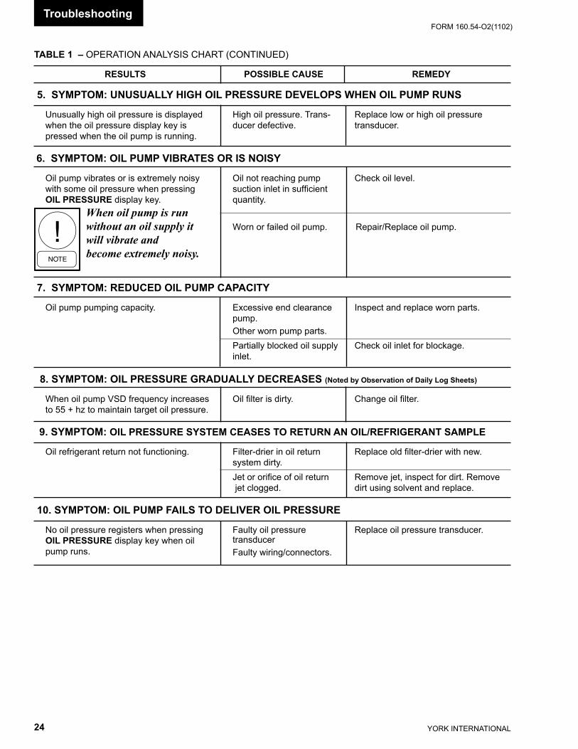
5. SYMPTOM: UNUSUALLY HIGH OIL PRESSURE DEVELOPS WHEN OIL PUMP RUNS
Unusually high oil pressure is displayed High oil pressure. Trans- Replace low or high oil pressure when the oil pressure display key is ducer defective. transducer. pressed when the oil pump is running.
6. SYMPTOM: OIL PUMP VIBRATES OR IS NOISY
Oil pump vibrates or is extremely noisy Oil not reaching pump Check oil level. with some oil pressure when pressing suction inlet in sufficient OIL PRESSURE display key. quantity.
When oil pump is run without an oil supply it Worn or failed oil pump. Repair/Replace oil pump.will vibrate and become extremely noisy.
7. SYMPTOM: REDUCED OIL PUMP CAPACITY
Oil pump pumping capacity. Excessive end clearance Inspect and replace worn parts. pump. Other worn pump parts. Partially blocked oil supply Check oil inlet for blockage. inlet. 8. SYMPTOM: OIL PRESSURE GRADUALLY DECREASES (Noted by Observation of Daily Log Sheets)
When oil pump VSD frequency increases Oil filter is dirty. Change oil filter. to 55 + hz to maintain target oil pressure.
9. SYMPTOM: OIL PRESSURE SYSTEM CEASES TO RETURN AN OIL/REFRIGERANT SAMPLE
Oil refrigerant return not functioning. Filter-drier in oil return Replace old filter-drier with new. system dirty. Jet or orifice of oil return Remove jet, inspect for dirt. Remove jet clogged. dirt using solvent and replace. 10. SYMPTOM: OIL PUMP FAILS TO DELIVER OIL PRESSURE
No oil pressure registers when pressing Faulty oil pressure Replace oil pressure transducer. OIL PRESSURE display key when oil transducer pump runs. Faulty wiring/connectors.
Troubleshooting
YORK INTERNATIONAL24
FORM 160.54-O2(1102) FORM 160.54-O2(1102)
25YORK INTERNATIONAL
SECTION 6MAINTENANCE
RENEWAL PARTS
For any required Renewal Parts, refer to YORK Re-newal Parts Unit Components Manual 160.73-RP1.
CHECKING SYSTEM FOR LEAKS
Leak Testing During OperationThe refrigerant side of the system is carefully pressure tested and evacuated at the factory.
After the system has been charged, the system should be carefully leak tested with a R-134a compatible leak detector to be sure all joints are tight.
If any leaks are indicated, they must be repaired im-mediately. Usually, leaks can be stopped by tighten-ing flare nuts or flange bolts. However, for any major repair, the refrigerant charge must be removed. (See “Handling Refrigerant for Dismantling and Repair”, page 29.)
CONDUCTING R-22 PRESSURE TEST
With the R-134a charge removed and all known leaks repaired, the system should be charged with a small amount of R-22 mixed with dry nitrogen so that a halide torch or electronic leak detector can be used to
detect any leaks too small to be found by the soap test.To test with R-22, proceed as follows:
1. With no pressure in the system, charge R-22 gas into the system through the charging valve to a pressure of 2 PSIG (14 kPa).
2. Build up the system pressure with dry nitrogen to approximately 75 to 100 PSIG (517 to 690 kPa). To be sure that the concentration of refrigerant has reached all part of the system, slightly open the oil charging valve and test for the presence of refrig-erant with a leak detector.
3. Test around each joint and factory weld. It is important that this test be thoroughly and carefully done, spending as much time as necessary and us-ing a good leak detector.
4. To check for refrigerant leaks in the evaporator and condenser, open the vents in the evaporator and condenser heads and test for the presence of refrig-erant. If no refrigerant is present, the tubes and tube sheets may be considered tight. If refrigerant is de-tected at the vents, the heads must be removed, the leak located (by means of soap test or leak detector) and repaired.
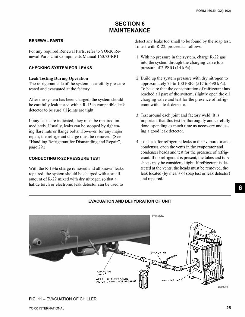
EVACUATION AND DEHYDRATION OF UNIT
FIG. 11 – EVACUATION OF CHILLER
27385A(D)
LD00949
6

YORK INTERNATIONAL26
FORM 160.54-O2(1102) FORM 160.54-O2(1102)
27YORK INTERNATIONAL
VACUUM TESTING
After the pressure test has been completed, the vac-uum test should be conducted as follows:
1. Connect a high capacity vacuum pump, with indi-cator, to the system charging valve as shown in Fig. 11 and start the pump. (See “Vacuum Dehy-dration”.)
2. Open wide all system valves. Be sure all valves to the atmosphere are closed.
3. Operate the vacuum pump in accordance with VACUUM DEHYDRATION until a wet bulb temperature of +32°F or a pressure of 5 mm Hg is reached. See Table 2 for corresponding values of pressure.
4. To improve evacuation circulate hot water (not to exceed 125°F, 51.7ºC) through the evaporator and condenser tubes to thoroughly dehydrate the shells. If a source of hot water is not readily avail-able, a portable water heater should be employed. DO NOT USE STEAM. A suggested method is to connect a hose between the source of hot water under pressure and the evaporator head drain con-nection, out the evaporator vent connection, into
the condenser head drain and out the condenser vent. To avoid the possibility of causing leaks, the temperature should be brought up slowly so that the tubes and shell are heated evenly.
5. Close the system charging valve and the stop valve between the vacuum indicator and the vacuum pump. Then disconnect the vacuum pump leaving the vacuum indicator in place.
6. Hold the vacuum obtained in Step 3 in the system for 8 hours; the slightest rise in pressure indicates a leak or the presence of moisture, or both. If, after 24 hours the wet bulb temperature in the vacuum indi-cator has not risen above 40°F (4.4°C) or a pressure of 6.3 mm Hg, the system may be considered tight.
Be sure the vacuum indicator is valved off while holding the system vacuum and be sure to open the valve between the vacuum indicator and the system when checking the vacuum after the 8 hour period.
7. If the vacuum does not hold for 8 hours within the limits specified in Step 6 above, the leak must be found and repaired.
TABLE 2 – SYSTEM PRESSURES
*GAUGE ABSOLUTE BOILING INCHES OF TEMPERATURES MERCURY (HG) MILLIMETERS OF BELOW ONE PSIA OF MERCURY MICRONS WATER STANDARD (HG) °F ATMOSPHERE
0 14.696 760. 760,000 212 10.24" 9.629 500. 500,000 192 22.05" 3.865 200. 200,000 151 25.98" 1.935 100. 100,000 124 27.95" .968 50. 50,000 101 28.94" .481 25. 25,000 78 29.53" .192 10. 10,000 52 29.67" .122 6.3 6,300 40 29.72" .099 5. 5,000 35 29.842" .039 2. 2,000 15 29.882" .019 1.0 1,000 +1 29.901" .010 .5 500 –11 29.917" .002 .1 100 –38 29.919" .001 .05 50 –50 29.9206" .0002 .01 10 –70 29.921" 0 0 0 *One standard atmosphere = 14.696 PSIA
= 760 mm Hg. absolute pressure at 32°F
= 29.921 inches Hg. absolute at 32°F
NOTES: PSIA = Lbs. per sq. in. gauge pressure = Pressure above atmosphere PSIA = Lbs. per sq. in. absolute pressure = Sum of gauge plus atmospheric pressure
Maintenance

YORK INTERNATIONAL26
FORM 160.54-O2(1102) FORM 160.54-O2(1102)
27YORK INTERNATIONAL
VACUUM DEHYDRATION
To obtain a sufficiently dry system, the following in-structions have been assembled to provide an effective method for evacuating and dehydrating a system in the field. Although there are several methods of dehy-drating a system, we are recommending the following, as it produces one of the best results, and affords a means of obtaining accurate readings as to the extent of dehydration.
The equipment required to follow this method of de-hydration consists of a wet bulb indicator or vacuum gauge, a chart showing the relation between dew point temperature and pressure in inches of mercury (vacuum), (See Table 2) and a vacuum pump capable of pumping a suitable vacuum on the system.
OPERATION
Dehydration of a refrigerant system can be obtained by this method because the water present in the system reacts much as a refrigerant would. By pull-ing down the pressure in the system to a point where its saturation temperature is considerably below that of room temperature, heat will flow from the room through the walls of the system and vaporize the wa-ter, allowing a large percentage of it to be removed by the vacuum pump. The length of time necessary for the dehydration of a system is dependent on the size or volume of the system, the capacity and efficiency of the vacuum pump, the room temperature and the quantity of water present in the system. By the use of the vacuum indicator as suggested, the test tube will be evacuated to the same pressure as the system, and the distilled water will be maintained at the same saturation temperature as any free water in the system, and this temperature can be observed on the thermom-eter.
If the system has been pressure tested and found to be tight prior to evacuation, then the saturation tempera-ture recordings should follow a curve similar to the typical saturation curve shown as Fig. 12.
The temperature of the water in the test tube will drop as the pressure decreases, until the boiling point is reached, at which point the temperature will level off and remain at this level until all of the water in the shell is vaporized. When this final vaporization has taken place the pressure and temperature will continue
to drop until eventually a temperature of 35°F (1.6°C) or a pressure of 5 mm Hg. is reached.When this point is reached, practically all of the air has been evacuated from the system, but there is still a small amount of moisture left. In order to provide a medium for carrying this residual moisture to the vacuum pump, nitrogen should be introduced into the system to bring it to atmospheric pressure and the indi-cator temperature will return to approximately ambient temperature. Close off the system again, and start the second evacuation.
The relatively small amount of moisture left will be carried out through the vacuum pump and the tem-perature or pressure shown by the indicator should drop uniformly until it reaches a temperature of 35°F (1.6°C) or a pressure of 5 mm Hg.
When the vacuum indicator registers this temperature or pressure, it is a positive sign that the system is evacuated and dehydrated to the recommended limit. If this level cannot be reached, it is evident that there is a leak somewhere in the system. Any leaks must be corrected before the indicator can be pulled down to 35°F or 5 mm Hg. in the primary evacuation.
During the primary pulldown, keep a careful watch on the wet bulb indicator temperature, and do not let it fall below 35°F (1.6°C). If the temperature is al-lowed to fall to 32°F (0°C), the water in the test tube will freeze, and the result will be a faulty temperature reading.
FIG. 12 – SATURATION CURVE
LD00474
6

YORK INTERNATIONAL28
FORM 160.54-O2(1102) FORM 160.54-O2(1102)
29YORK INTERNATIONAL
REFRIGERANT CHARGINGTo avoid the possibility if freezing liquid within the evaporator tubes when charging an evacuated sys-tem, only refrigerant vapor from the top of the drum or cylinder must be admitted to the system pressure until the system pressure is raised above the point corresponding to the freezing point of the evaporator liquid. For water, the pressure corresponding to the freezing point is 8.54 PSIG (58.9 kPa) for R-134a (at sea level).
While charging, every precaution must be taken to pre-vent moisture laden air from entering the system. Make up a suitable charging connection from new copper tubing to fit between the system charging valve and the fitting on the charging drum. This connection should be as short as possible but long enough to permit sufficient flexibility for changing drums. The charging con-nection should be purged each time a full container of refrigerant is connected and changing containers should be done as quickly as possible to minimize the loss of refrigerant.
Refrigerant may be furnished in cylinders containing either 30, 50, 125 or 1750 lbs. (207, 345, 862, or 12,066 kg) of refrigerant.
TABLE 3 – REFRIGERANT CHARGE
CHECKING THE REFRIGERANT CHARGEDURING UNIT SHUTDOWN
The refrigerant charge is specified for each chiller model (See Table 3). Charge the correct amount of refrigerant and record the level in the evaporator sight glass.
The refrigerant charge should always be checked and trimmed when the system is shut down.
The refrigerant charge level must be checked after the pressure and temperature have equalized between the
condenser and evaporator. This would be expected to be 4 hours or more after the compressor and water pumps are stopped. The level should visible in the sight glass.
Charge the refrigerant in accordance with the method shown under the “Refrigerant Charging”, above. The refrigerant level should be observed and the level recorded after initial charging.
Maintenance
R-134aSHELL CODES
LBS. / KGEVAPORATOR CONDENSER
* A * A 1250 / 567* B * B 1550 / 703* C * C 1600 / 726* D * D 1900 / 862C C 1350 / 612C D 1400 / 635D C 1420 / 644D D 1470 / 666D E 1590 / 721E D 1590 / 721E E 1690 / 766E F 1790 / 811F E 1900 / 861F F 2020 / 916F G 2150 / 975G F 2290 / 1038G G 2415 / 1095H G 2625 / 1190G H 2560 / 1161H H 2825 / 1285H J 3010 / 1365J H 3310 / 1501J J 3495 / 1585T T 3995 / 1812T V 4290 / 1945V T 3820 / 1732V V 4150 / 1882W V 4460 / 2023
* - Chillers with P1, P2, P3, P4, P5, P6, and P7 compressors only.
YORK INTERNATIONAL28
FORM 160.54-O2(1102) FORM 160.54-O2(1102)
29YORK INTERNATIONAL
HANDLING REFRIGERANT FORDISMANTLING AND REPAIRS
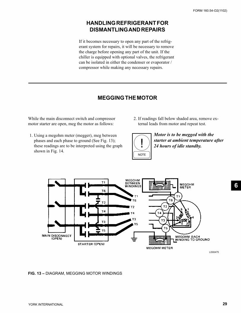
MEGGING THE MOTOR
If it becomes necessary to open any part of the refrig-erant system for repairs, it will be necessary to remove the charge before opening any part of the unit. If the chiller is equipped with optional valves, the refrigerant can be isolated in either the condenser or evaporator / compressor while making any necessary repairs.
While the main disconnect switch and compressor motor starter are open, meg the motor as follows:
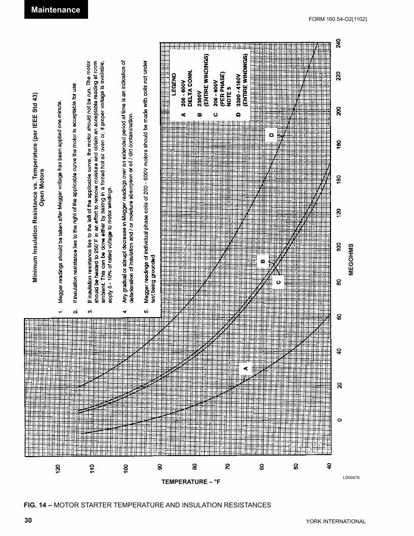
1. Using a megohm meter (megger), meg between phases and each phase to ground (See Fig. 13); these readings are to be interpreted using the graph shown in Fig. 14.
2. If readings fall below shaded area, remove ex-ternal leads from motor and repeat test.
Motor is to be megged with the starter at ambient temperature after 24 hours of idle standby.
FIG. 13 – DIAGRAM, MEGGING MOTOR WINDINGS
LD00475
6
YORK INTERNATIONAL30
FORM 160.54-O2(1102) FORM 160.54-O2(1102)
31YORK INTERNATIONAL
LD00476
FIG. 14 – MOTOR STARTER TEMPERATURE AND INSULATION RESISTANCES
Min
imum
Insu
latio
n R
esis
tanc
e vs
. Tem
pera
ture
(per
IEEE
Std
43)
Ope
n M
otor
s
Maintenance
TEMPERATURE – °F
MEG
OH
MS
YORK INTERNATIONAL30
FORM 160.54-O2(1102) FORM 160.54-O2(1102)
31YORK INTERNATIONAL
CONDENSERS AND EVAPORATORSGENERAL
Maintenance of condenser and evaporator shells is important to provide trouble free operation of the chiller. The water side of the tubes in the shell must be kept clean and free from scale. Proper maintenance such as tube cleaning, and testing for leaks, is covered on the following pages.
CHEMICAL WATER TREATMENT
Since the mineral content of the water circulated through evaporators and condensers varies with almost every source of supply, it is possible that the water being used may corrode the tubes or deposit heat resistant scale in them. Reliable water treatment companies are available in most larger cities to supply a water treating process which will greatly reduce the corrosive and scale form-ing properties of almost any type of water.
As a preventive measure against scale and corrosion and to prolong the life of evaporator and condenser tubes, a chemical analysis of the water should be made pref-erably before the system is installed. A reliable water treatment company can be consulted to determine wheth-er water treatment is necessary, and if so, to furnish the proper treatment for the particular water condition.
CLEANING EVAPORATOR AND CONDENSER TUBES
EvaporatorIt is difficult to determine by any particular test whether possible lack of performance of the water evaporator is due to fouled tubes alone or due to a combination of troubles. Trouble which may be due to fouled tubes is indicated when, over a period of time, the cooling capacity decreases and the split (temperature difference between water leaving the evaporator and the refrigerant temperature in the evaporator) increases. A gradual drop-off in cooling capacity can also be caused by a gradual leak of refrigerant from the system or by a combination of fouled tubes and shortage of refrigerant charge. An excessive quantity of oil in the evaporator can also con-tribute to erratic performance.
CondenserIn a condenser, trouble due to fouled tubes is usually indicated by a steady rise in head pressure, over a period of time, accompanied by a steady rise in condensing temperature, and noisy operation. These symptoms may also be due to foul gas buildup. Purging will remove the foul gas revealing the effect of fouling.
TUBE FOULING
Fouling of the tubes can be due to deposits of two types as follows: 1. Rust or sludge – which finds its way into the tubes
and accumulates there. This material usually does not build up on the inner tube surfaces as scale, but does interfere with the heat transfer. Rust or sludge can generally be removed from the tubes by a thor-ough brushing process.
2. Scale – due to mineral deposits. These deposits, even though very thin and scarcely detectable upon physical inspection, are highly resistant to heat transfer. They can be removed most effectively by circulating an acid solution through the tubes.
TUBE CLEANING PROCEDURES
Brush Cleaning of TubesIf the tube consists of dirt and sludge, it can usually be removed by means of the brushing process. Drain the water sides of the circuit to be cleaned (cooling water or chilled water) remove the heads and thoroughly clean each tube with a soft bristle bronze or nylon brush. DO NOT USE A STEEL BRISTLE BRUSH. A steel brush may damage the tubes.
Improved results can be obtained by admitting water into the tube during the cleaning process. This can be done by mounting the brush on a suitable length of 1/8" pipe with a few small holes at the brush end and connecting the other end by means of a hose to the water supply.
The tubes should always be brush cleaned before acid cleaning.
ACID CLEANING OF TUBES
If the tubes are fouled with a hard scale deposit, they may require acid cleaning. It is important that before acid cleaning, the tubes be cleaned by the brushing process described above. If the relatively loose foreign material is removed before the acid cleaning, the acid solution will have less material to dissolve and flush from the tubes with the result that a more satisfactory cleaning job will be accomplished with a probable saving of time.
Acid cleaning should only be per-formed by an expert. Please consult your local water treatment represent-ative for assistance in removing scale buildup and preventative maintenance programs to eliminate future prob-lems.
6
YORK INTERNATIONAL32
FORM 160.54-O2(1102) FORM 160.54-O2(1102)
33YORK INTERNATIONAL
COMMERCIAL ACID CLEANING
In many major cities, commercial organizations now offer a specialized service of acid cleaning evapora-tors and condensers. If acid cleaning is required, YORK recommends the use of this type of organiza-tion. The Dow Industries Service Division of the Dow Chemical Company, Tulsa, Oklahoma, with branches in principal cities is one of the most reliable of these companies.
TESTING FOR EVAPORATOR AND CONDENSER TUBE LEAKS
Evaporator and condenser tube leaks in R-134a systems may result in refrigerant leaking into the water circuit, or water leaking into the shell depend-ing on the pressure levels. If refrigerant is leaking into the water, it can be detected at the liquid head vents after a period of shutdown. If water is leaking into the refrigerant, system capacity and efficiency will drop off sharply. If a tube is leaking and water has entered the system, the evaporator and condenser should be valved off from the rest of the water circuit and drained immediately to prevent severe rusting and corrosion. The refrigerant system should then be drained and purged with dry nitrogen to prevent se-vere rusting and corrosion. If a tube leak is indicated, the exact location of the leak may be determined as follows:
1. Remove the heads and listen at each section of tubes for a hissing sound that would indicate gas leakage. This will assist in locating the section of tubes to be further investigated. If the probable location of the leaky tubes has been determined, treat that section in the following manner (if the location is not definite, all the tubes will require investigations).
2. Wash off both tube heads and the ends of all tubes with water.
Do not use carbon tetrachloride for this purpose since its fumes give the same flame discoloration that the refrigerant does.
3. With nitrogen or dry air, blow out the tubes to clear them of traces of refrigerant laden moisture from the circulation water. As soon as the tubes are clear, a cork should be driven into each end of the tube. Pressurize the dry system with 50 to 100 PSIG (345 to 690 kPa) of nitrogen. Repeat this with all of the other tubes in the suspected section or, if necessary, with all the tubes in the evaporator or condenser. Allow the evaporator or condenser to remain corked up to 12 to 24 hours before proceeding. Depending upon the amount of leak-age, the corks may blow from the end of a tube, indicating the location of the leakage. If not, if will be necessary to make a very thorough test with the leak detector.
4. After the tubes have been corked for 12 to 24 hours, it is recommended that two men working at both ends of the evaporator carefully test each tube – one man removing corks at one end and the other at the opposite end to remove corks and handle the leak detector. Start with the top row of tubes in the section being investigated. Remove the corks at the ends of one tube simultaneously and insert the exploring tube for 5 seconds – this should be long enough to draw into the detector any refrigerant gas that might have leaked through the tube walls. A fan placed at the end of the evaporator opposite the detector will assure that any leakage will travel through the tube to the detector.
5. Mark any leaking tubes for later identification.
6. If any of the tube sheet joints are leaking, the leak should be indicated by the detector. If a tube sheet leak is suspected, its exact location may be found by using a soap solution. A continuous buildup of bubbles around a tube indicates a tube sheet leak.
Maintenance

YORK INTERNATIONAL32
FORM 160.54-O2(1102) FORM 160.54-O2(1102)
33YORK INTERNATIONAL
COMPRESSOR
ELECTRICAL CONTROLS
Maintenance for the compressor assembly consists of checking the operation of the oil return system and changing the dehydrator, checking and changing the oil, checking and changing the oil filters, checking the operation of the oil heater, checking the operation of the oil pump, and observing the operation of the com-pressor.
Internal wearing of compressor parts could be a serious problem caused by improper lubrication, brought about by restricted oil lines, passages, or dirty
oil filters. If the unit is shutting down on (HOT) High Oil Temperature or Low Oil Pressure (OP), change the oil filter element. Examine the oil filter element for the presence of aluminum particles. Aluminum gas seal rings can contact the impeller and account for some aluminum particles to accumulate in the oil filter, espe-cially during the initial start up and first several months of operation. However, if aluminum particles continue to accumulate and the same conditions continue to stop the unit operation after a new filter is installed, notify the nearest YORK office to request the presence of a YORK Service Technician.
For information covering the OptiView™ Control Center operation, refer to Form 160.54-O1.
6

YORK INTERNATIONAL34
FORM 160.54-O2(1102) FORM 160.54-O2(1102)
35YORK INTERNATIONAL
SECTION 7PREVENTIVE MAINTENANCE
It is the responsibility of the owner to provide the necessary daily, monthly and yearly maintenance requirements of the system. IMPORTANT – If a unit failure occurs due to improper maintenance during the warranty period; YORK will not be liable for costs incurred to return the system to satisfactory operation.
In any operating system it is most important to provide a planned maintenance and inspection of its functioning parts to keep it operating at its peak ef-ficiency. Therefore, the following maintenance should be performed when prescribed.
COMPRESSOR
1. Oil Filter – When oil pump VSD frequency in-creases to 55 hz to maintain target oil pressure.
When the oil filter is changed, it should be in-spected thoroughly for any aluminum particles which would indicate possible bearing wear. If aluminum particles are found this should be brought to the attention of the nearest YORK of-fice for their further investigation and recommen-dations.
2. Oil Changing – The oil in the compressor must be changed annually or earlier if it becomes dark or cloudy. However, quarterly oil analysis can elim-inate the need for an annual change provided the analysis indicates there is no problem with the oil.
COMPRESSOR MOTOR
1. Check motor mounting screws frequently to insure tightness.
2. Meg motor windings annually to check for dete-rioration of windings.
GREASED BEARINGS ON RELIANCE Q5800 MOTORS
Motor Operation and Maintenance manuals are sup-plied with the chillers providing maintenance sched-ules and instructions for the specific motors. The fol-lowing are lubrication schedules for the most common motors:
Toshiba Motor LubricationFrame 143T thru 256T are furnished with double sealed ball bearings, pre-lubricated prior to installa-
tion. Grease fittings are not supplied and bearings are designed for long life under standard conditions.
Frames 284T thru 587UZ are furnished with double shielded or open ball or roller bearings. It is neces-sary to re-lubricate anti-friction bearings periodically. (See Table 4)
Frame Size
Standard 8hr/Day
Continuous 24hr Day
Grease Qty. oz.
143T-256T *7 Years *3 Years *1284TS - 286TS 210 Days 70 Days 1
324TS - 587USS 150 Days 50 Days 2
* - On frame sizes 143T - 256T, changing bearings at these inter-vals is recommended. However, removing the seal, cleaning and refilling the bearing and the cavity with recommended grease can re-lubricate these bearings.
Reliance motors in the 5800 frame size are equipped entirely with grease-lubricated ball-bearings. The fol-lowing outlines the lubrication requirements for these bearings:• The motor bearings are properly lubricated as
received from YORK. There is no need to add lubricant to the motor bearings at start-up. Too much grease in the motor bearing cavity may cause excessive bearing temperature.
• If the motor has been in storage for 6 months prior to commissioning, lubricate the motor bearings per the following instructions prior to start-up.
• If the motor is inactive for 30 days, the motor shaft is to be rotated 15 revolutions in order to distribute the grease within the bearing.
• Some bearing squeal may be noted at start-up. This is often due to the bearing cage, as it vibrates against the moving bearing elements. This noise should sub-side after a few days of operation. Inter-mittent bear-ing squeal is not cause for alarm.
• Use only Texaco Premium RB (Code 1939) grease to lubricate the motor bearings, as indicated in Reliance literature for these motors. The grease is readily available throughout most of the world, from Texaco distributors – and in Africa, Australia, and the Pacific Rim countries from Caltex dis-tributors. Other types of grease may be chemically and mechanically incompatible with this Texaco Premium RB grease, and are not to be used.
Preventive Maintenance
TABLE 4 – BEARING LUBRICATION

YORK INTERNATIONAL34
FORM 160.54-O2(1102) FORM 160.54-O2(1102)
35YORK INTERNATIONAL
• Add 1.5 cubic inches of Texaco Premium RB grease every 1800 hours of operation of the motor. Do not expect to see grease exiting the grease relief port during these re-lubrications.
Additional information on motor lubrication and other service issues can be found in the A-C Motors Instruction Manual.
Recommended greases for standard applications:OPERATING AMBIENT TEMP. -30ºC to 50ºC
Chevron SRI (Chevron)Exxon Unirex #2 (Exxon Corp.)Exxon Polyrex (Exxon Corp.)Shell Dolum R (Shell Oil Co.)
Mixing different greases is not recommended
Westinghouse Motor Lubrication:• Re-greasing should occur at 1000 operating hour
intervals. • Westinghouse recommends using Westinghouse
Grease No. 53701. • Motors with shaft diameters less than 2 3/8 inch
require 1 oz of grease per bearing while motors with shaft diameters between 2 3/8 and 3 inches require 1.5 oz.
LEAK TESTINGThe unit should be leak tested quarterly. Any leaks found must be repaired immediately.
EVAPORATOR AND CONDENSERThe major portion of maintenance on the condenser and evaporator will deal with the maintaining the water side of the condenser and evaporator in a clean condition.
The use of untreated water in cooling towers, closed water systems, etc. frequently results in one or more of the following:
1. Scale Formation. 2. Corrosion or Rusting. 3. Slime and Algae Formation.
It is therefore to the benefit of the user to provide for proper water treatment to provide for a longer and more economical life of the equipment. The following recommendation should be followed in determining the condition of the water side of the condenser and evaporator tubes.
1. The condenser tubes should be cleaned annually or earlier if conditions warrant. If the temperature difference between the water off the condenser and the condenser liquid temperature is more than 4°F (2°C) greater than the difference recorded on a new unit, it is a good indication that the condenser tubes require cleaning. Refer to the Maintenance section of this manual for condenser tube cleaning instructions.
2. The evaporator tubes under normal circumstances will not require cleaning. If however the tem-perature difference between the refrigerant and the chilled water increases slowly over the operating season, it is an indication that the evaporator tubes may be fouling or that there may be a water bypass in the water box requiring gasket replacement or refrigerant may have leaked from the chiller.
OIL RETURN SYSTEM
1. Change the dehydrator in the oil return system semiannually or earlier if the oil return system fails to operate.
2. When the dehydrator is changed, the nozzle of the eductor should be checked for any foreign par-ticles that may be obstructing the jet.
ELECTRICAL CONTROLS
1. All electrical controls should be inspected for obvious malfunctions.
2. It is important that the factory settings of controls (operation and safety) not be changed. If the set-tings are changed without YORK’s approval, the warranty will be jeopardized.
7
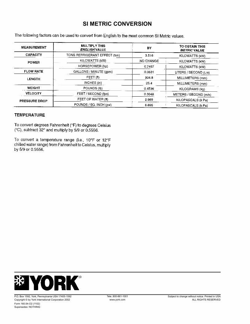
SI METRIC CONVERSION
Tele. 800-861-1001www.york.com
P.O. Box 1592, York, Pennsylvania USA 17405-1592 Subject to change without notice. Printed in USACopyright © by York International Corporation 2002 ALL RIGHTS RESERVEDForm 160.54-O2 (1102) Supersedes: NOTHING