modeling activities of the institute of power engineering ... · pdf filemodeling activities...
TRANSCRIPT

Modeling activities of the Institute of Power Engineering in ONSITE Project
Jakub KupeckiKonrad Motylioski
Marcin Błesznowski
Department of High Temperature Electrochemical Processes, Warsaw, Poland
Previously:Thermal Processes Department, Warsaw, Poland
Rome, September 22nd, 2017

Modeling activities realized within
ONSITE project (Operation of a Novel SOFC-battery Integrated hybrid for Telecommunication Energy systems)
financed through:
Grant agreement number: 325325
2 of 42

Modeling activities (Aspen® Hysys 8.8 and ANSYS® Fluent 17)
o SOFC stack stationary modelo SOFC stack dynamic modelo SoNick battery moduleo SOFC/SNC hybrid systemo SOFC/SNC thermal integration
Deliverables
o D2.2 Preliminary, stationary model of SOFC stacko D2.3 Preliminary, BoP model of the SOFC/battery systemo D2.5 Final report of SOFC/SNC hybrid system modeling
Publications and conferences
Summary
Presentation plan
3 of 42
4 of 42
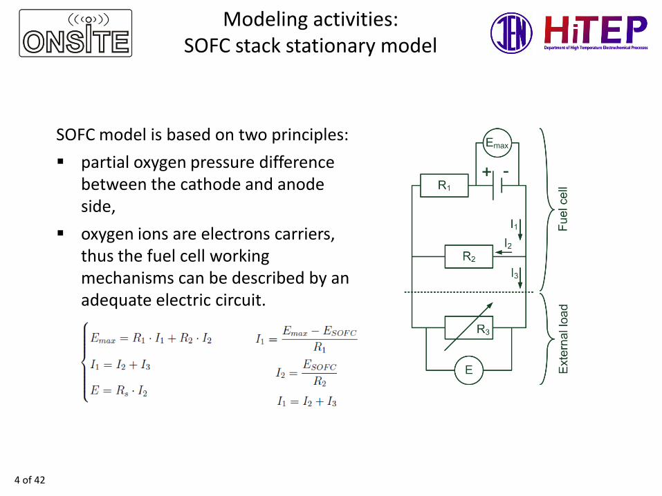
SOFC model is based on two principles:
partial oxygen pressure difference between the cathode and anode side,
oxygen ions are electrons carriers, thus the fuel cell working mechanisms can be described by an adequate electric circuit.
Modeling activities:SOFC stack stationary model

Modeling activities:SOFC stack stationary model
5 of 42
SOFC voltage (based on Ohms and Kirchhoff's Laws):
Maximal voltage of the fuel cell determined by maximal work realized in isothermal process (based on Nernst equation):
Maximal current density (based on Faraday’s Law)
SOFC current is correlated with fuel flow, thus fuel utilization ratio was proposed:
Open circuit voltage:
Equation of state Peng-Robinson:

Modeling activities:SOFC stack stationary model
6 of 42
SOFC voltage (based on Ohms and Kirchhoff's Laws):
Parameters of SOFC are included in the model
Kupecki J., Milewski J., Jewulski J., Investigation of SOFC material properties for plant-level
modeling, Central European Journal of Chemistry, 2013;11(5):664-671.

7 of 42
Modeling activities: SOFC stackstationary model - stack parameters
Item Specification CommentStack 2x Mk200, 60 cells in totalCells Electrolyte supported cells (ESC) Cells with 3YSZ electrolyteSeals for interconnectors Glass / ceramic Stamped sheet
metalCrofer 22 APU
Item Specification CommentElectrical power, W ≥1300 At current interfaceVoltage, V ≥38 At current interfaceAnode gas composition 40% H2 in N2 Without humidificationAnode gas inlet temperature, °C 750 Anode inlet thermocoupleCathode composition Atmospheric
(ambient air)Alternative: dry compressed air
Cathode flow rate during full load, Nl/min
≈245 Flow rate is adjusted to control stack operating temperature
Cathode inlet temperature, °C 650 Cathode inlet thermocoupleOperating temperature, °C 850 – 860 Whichever stack core temperature is
the highest from four thermocouples inside the stack
Operating pressure, mbar gauge 5 –10Volume, dm3 85.5Mass, kg 65

8 of 42
Modeling activities: SOFC stackstationary model - stack parameters
Item Limit CommentMaximum cathode inlet temperature, °C 850Maximum cathode exhaust temperature, °C 840Maximum anode inlet temperature, °C 850Maximum stack core temperature, °C 860Maximum cathode inlet temperature gradients, K/min
10 Heating up to the operating temperature
Maximum cathode inlet temperature gradients, K/min
5 Cooling down from the operating temperature
Maximum temperature difference anode inlet–cathode inlet, K
50 Anode inlet thermocouple
Maximum pressure difference anode–cathode, hPa
30
Maximum operating pressure, hPa gauge 30 Related to ambient pressureMinimum operation voltage, V 6 Per 10-cell blockMinimum operation voltage, V 36 At current interfaceCurrent ramp, A/min 2 Increasing currentCurrent ramp, A/min 30 Decreasing currentMaximum air utilization, % 30Maximum fuel utilization, % 80

9 of 42
Relative model error lower than 5%
Modeling activities: SOFC stackstationary model - validation

10 of 42
Modeling activities: Fully physicalSOFC stack dynamic model

11 of 42
Modeling activities: SOFC stack dynamicmodel - calculation algorithm

12 of 42
Modeling activities: SOFC stack dynamicmodel - control module

13 of 42
Relative model error was lower than 10% during transient operation and 4.5% during quasi steady-state without rapid load changes
Modeling activities: SOFC stackdynamic model - validation

14 of 42
Modeling activities: SoNickbattery module dynamic model
In ONSITE project, FIAMM has suggested and delivered a 48TL200 model of the SoNick battery type. The main parameters of 48TL200 battery are listed below:• nominal Voltage: 48 VDC• open Circuit Voltage: 51.6V• bus Voltage Range: 53 to 59 V• nominal Capacity: 200 Ah at C4 to 42V• faradic Charge Efficiency: 100%

15 of 42
Modeling activities: SoNickbattery module dynamic model
Experimental data Results generated by the dynamic model
Empirical numerical model of the SoNickmodule is based on experimental data,including SOC, voltage, internal temperaturefor various operating parameters.

16 of 42
Modeling activities:SOFC/SNC hybrid system

17 of 42
Modeling activities:SOFC/SNC thermal integration
Inlet
Outlet
Flow and temperature data of residual gas from cogeneration system with SOFC cell stack
Connection concept of set of two SNC batteries to a cogeneration system with a SOFC stack
Numerical simulations of SOFC/SNC thermalintegration were performed using commercialsoftware (ASNYS Fluent®) and own computationalcodes
Material data of insulation (microporous plates)and measured waste gas parameters wereimplemented in the calculation model:o temperature of gas: 239°Co mass flow: 0.025 kg/so gas composition:
• O2 17.1 %vol.
• CO2 2.2 %vol.
• CO 15 ppm

18 of 42
Modeling activities:SOFC/SNC thermal integration
Four conceptions of gas distribution in the duct between the internal and external insulation of the SNC battery
1st 2nd 3rd 4th
19 of 42
Deliverable D2.2 Preliminary, stationary model of SOFC stack
Description of the deliverable:
• Development and implementation of the SOFC stack stationary model
• Performed simulations of SOFC stack performance under nominal working conditions and during off-design operation
• Designed stationary model was used as a base for the SOFC stack dynamic model

20 of 42
Deliverable D2.2 Preliminary, stationary model of SOFC stack
Stack voltage vs. fuel flow obtained from the model for 700°C and 800°C

21 of 42
Deliverable D2.2 Preliminary, stationary model of SOFC stack
Stack power vs. fuel flow obtained from the model for 700°C and 800°C

22 of 42
Deliverable D2.3 Preliminary, BoPmodel of the SOFC/battery system
Description of the deliverable:
• Development and implementation of the SOFC stack dynamic model
• Development and implementation of the SoNick battery module dynamic model
• Performed simulations of SOFC stack transient performance under various operating scenarios
• Performed simulations of SOFC/SoNick hybrid system responding to different power demand profiles of base-load telecommunication system

23 of 42
Deliverable D2.3 Preliminary, BoPmodel of the SOFC/battery system
Model prediction for three thermal cycles of a SOFC stack with degradation rate of 0.525% per cycle

24 of 42
Deliverable D2.3 Preliminary, BoPmodel of the SOFC/battery system
Parameters of the inlet and outlet streams in co-current flow configuration

25 of 42
Deliverable D2.3 Preliminary, BoPmodel of the SOFC/battery system
Parameters of the inlet and outlet streams in counter-current flow configuration

26 of 42
Deliverable D2.3 Preliminary, BoPmodel of the SOFC/battery system
Parameters of the inlet and outlet streams in cross-flow configuration

27 of 42
Deliverable D2.3 Preliminary, BoPmodel of the SOFC/battery system
Comparison of anode outlet temperature obtained from the model for co–, counter–current and cross–flow configuration
28 of 42
Deliverable D2.3 Preliminary, BoPmodel of the SOFC/battery system
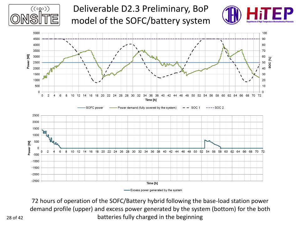
72 hours of operation of the SOFC/Battery hybrid following the base-load station power demand profile (upper) and excess power generated by the system (bottom) for the both
batteries fully charged in the beginning

29 of 42
Deliverable D2.3 Preliminary, BoPmodel of the SOFC/battery system
72 hours of operation of the SOFC/Battery hybrid following the base-load station power demand profile (upper) and excess power generated by the system (bottom) for the main
battery (1) fully discharged and additional battery (2) fully charged in the beginning

30 of 42
Deliverable D2.3 Preliminary, BoPmodel of the SOFC/battery system
72 hours of operation of the SOFC/Battery hybrid following the base-load station power demand profile (upper) and excess power generated by the system (bottom) for the both
batteries fully discharged in the beginning
31 of 42
Deliverable D2.5 Final report ofSOFC/SNC hybrid system modeling
Description of the deliverable:
• Expansion of SOFC stack dynamic model with PID-based control module and direct internal reforming mechanisms
• Performed additional simulations of SOFC stack operation for different scenarios (i.e. failure modes, 2-stack integration)
• Performed additional simulations of SOFC/SNC hybrid system for extended base-load telecommunication system operation up to 2 weeks
• Development and implementation of SOFC/SNC thermal integration CFD model

32 of 42
Deliverable D2.5 Final report ofSOFC/SNC hybrid system modeling
After 30 minutes of operation, a partialleakage occurs in the oxidant pipe, and only30% of the oxidant stream is delivered to thestack. As a result the in-stack temperaturerises above the allowed level and theregulator reduces the stack current in orderto prevent the overheating
After 50 and 60 minutes of operation, the fault of two 6-cell modules occurs. In order to maintain 1 kW ofgenerated power, regulator adjust the stack current to theproper level for each of the defected module
SOFC stack system failure modes

33 of 42
Deliverable D2.5 Final report ofSOFC/SNC hybrid system modeling
After 20 and 40 minutes of operation, stack’scurrent drops drastically. As a result,temperature of outlet gases also decreases,but proper regulators keep it high enough inorder not to exceed the lower limits of thetemperature for the SOFC stack operation
After 30 minutes of stack operation, the steam reformerfails, thus biogas is fueling directly the SOFC stack. As aresult, power decreases and the regulators of the inlettemperature adjust temperature to recover thermalbalance of the unit
SOFC stack system failure modes

34 of 42
Deliverable D2.5 Final report ofSOFC/SNC hybrid system modeling
Model prediction for two stacks operating in series during start-up phase
0
200
400
600
800
1000
1200
0
100
200
300
400
500
600
700
800
0 5000 10000 15000 20000
Sta
ck
po
we
r [W
]
Te
mp
era
ture
[ C
]
Time [s]
First stack anode outlet temperature First stack cathode outlet temperature
Second stack anode outlet temperature Second stack cathode outlet temperature
First stack power Second stack power

35 of 42
Deliverable D2.5 Final report ofSOFC/SNC hybrid system modeling
2 weeks long operation of the SOFC-SNC hybrid following the base-load station power demand profile (upper) and excess power
generated by the system (bottom)

36 of 42
Deliverable D2.5 Final report ofSOFC/SNC hybrid system modeling
2 weeks long operation of the SOFC-SNC hybrid following the base-load station power demand profile (upper) and excess power
generated by the system (bottom)

37 of 42
Deliverable D2.5 Final report ofSOFC/SNC hybrid system modeling
Profile of temperature and flow in case of heating the battery (operating at 200°C) with waste gas 239°C (3rd concept of gas distribution)
Temperature [K] Velocity [m/s]

38 of 42
Deliverable D2.5 Final report ofSOFC/SNC hybrid system modeling
Profile of temperature and flow in case of heating the battery (operating at 350°C) with waste gas 239°C (3rd concept of gas distribution)
Temperature [K] Velocity [m/s]

39 of 42
Deliverable D2.5 Final report ofSOFC/SNC hybrid system modeling
Temperature profile of SNC battery with all layers of insulation(4th concept of gas distribution)

40 of 42
Publications and conferences
• Kupecki J., Milewski J., Szczęśniak A., Bernat R., Motylioski K., Dynamic numerical analysis of cross-, co-, and counter-current flow configuration of a 1 kW-class solid oxide fuel cell stack, International Journalof Hydrogen Energy 2015;40(45):15834-15844
• Kupecki J., Motylinski K., Ferraro M., Sergi F., Zanon N., Use of NaNiCl battery for mitigation of SOFC stack cycling in base-load telecommunication power system – a preliminary evaluation, Journal of Power Technologies 2016;96(1):63-71
• Kupecki J., Motylinski K., Milewski J., Dynamic analysis of direct internal reforming in a SOFC stack with electrolyte-supported cells using a quasi-1D model, Applied Energy 2017, In press
• (Presentation) Kupecki J., Motylinski K., Zanon N., Dona I., Modeling of transitional states of a molten salt battery as a part of cogenerative power system with solid oxide fuel cells, 6th World Hydrogen Technologies Convention, Sydney, Australia, 11-14.10.2015
• (Presentation) Kupecki J., Motylinski K., Use of a molten salt battery solid oxide fuel cell stack hybrid for base-load telecommunication system - a numerical study, XII Research & Development In Power Engineering Conference (RDPE 2015), Warsaw, 8-11.12.2015
• (Presentation) Milewski J., Kupecki J., Szczesniak A., Motylinski K., Bernat R., The influence of electrolyte type on dynamic response of 1 kW-size SOFC stack, 6th European Fuel Cell Piero LunghiConference (EFC15), Naples, Italy, 16-18.12.2015
• (Presentation) Motylinski K., Kupecki J., Milewski J., Stefanski M., Bonja M., Control-oriented dynamicmodel of a 1 kW-class SOFC stack for simulation of failure modes, Proceedings of XXI World HydrogenEnergy Conference (WHEC 2016), Saragossa, Spain, 13-16.06.2016
• (Presentation) Brunaccini G., Sergi F., Aloisio D., Ferraro M., Blesznowski M., Kupecki J., Motylinski K., Antonucci V., Electrical and thermal integration modeling of a hybrid supply system, EuropeanMaterials Research Society (EMRS) Fall Meeting 2016, Warsaw, Poland, 19-22.09.2016

41 of 42
Summary
• Fully physical, SOFC dynamic model was designed and implemented in Aspen Hysys modeling software
• Model validation and simulations for different operating scenarios were performed
• Dynamic SOFC-SNC electrical model was designed and used for simulations of long-term various power demands scenarios of base-load telecommunication system
• CFD thermal analysis of battery heating system was performed, including different configuration of hot gas channels/zones

Modeling activities of the Institute of Power Engineering in ONSITE Project
Jakub KupeckiKonrad Motylioski
Marcin Błesznowski
Thank you for your attention