modeling and analysis of a rocket based combined cycle ... · carried out in fluent 13.0. ......
TRANSCRIPT

IOSR Journal of Mechanical and Civil Engineering (IOSR-JMCE)
e-ISSN: 2278-1684,p-ISSN: 2320-334X, Volume 11, Issue 1 Ver. I (Jan. 2014), PP 01-12
www.iosrjournals.org
www.iosrjournals.org 1 | Page
Modeling and Analysis of a Rocket Based Combined Cycle
Rocket Nozzle
A Kalyan Charan, D Madhava Reddy, CH Rakesh (Mechanical Department, KNRCER/JNTUH, INDIA)
Abstract : This project develops a rocket nozzle. The nozzle is designed in such a way that the divergent
portion of the nozzle geometry must pass through a clover that is placed on the perimeter, thus creating a space
for air intake into the centre of an annular rocket exhaust stream. The main objective of this project is to
determine the best one from (3clover, 4clover and 5 clovers) and comparison of numerical simulation to a
predefined Mach number distribution of in viscid solution and viscous simulation using the k-
model will be attempted. Geometry designs and Meshing were made in ICEM CFD 13.0 and an analysis is
carried out in FLUENT 13.0. Based on the flow analysis it is found that nozzle with 4 clovers/gates provides
better results when compared with the other i.e., 3 or 5 clovers/gates and it is one of the suggested and effective
design of the nozzle. In viscid area-averaged computational results are within 2.1% of the predefined outlet
Mach number of 2.75 and 7.6% of the isentropic pressure predicted at the outlet. Viscous computational results
obtained using the k-e turbulence model under-predict the predefined outlet Mach number by 4% which is
acceptable.
Keywords: CFD, Mach, RBCC, Rocket Nozzle.
I. Introduction: Since propellants can account for upwards of 90% of the vehicle’s initial mass
[1, 3] and the high costs
required for launch, extensive efforts have gone into the improvement of rocket systems. Major work since the
inception of rockets has gone into several fields: (1) Propellant choice; (2) Feed system design; (3) Increasing
thrust chamber performance; (4) Maximizing area expansion ratio through improved nozzle design; and (5)
Multistaging. Concepts still in development include (6) rocket-based combined cycles and (7) liquid-air cycle
engines. The motivation behind these seven concepts is to increase the performance qualifiers thrust FT or
specific impulse ISP or reduce initial rocket mass. Five of the seven fields for improving rocket design
propellant choice, feed system design, thrust chamber performance, nozzle improvements , and multistaging
have been well examined and implemented to the extent that there is very little room for additional
improvement. The focus of this research is based on the expectation that entraining air into the centre of an
annular rocket exhaust stream causes the ejector effect necessary for the ejector mode of RBCC operation.
Anticipated benefits to pursuing this concept include higher thrust due to increased mixing ability between the
higher annular rocket exhaust velocity and entrained air along the central axis as compared to entraining air on
the annulus with the rocket located along the central axis and a more convenient mounting configuration for an
axisymmetric ejector duct since it can be attached directly to the outer wall of the rocket nozzle.
II. Proposed Rocket Nozzle Rbcc:
This project is based on the expectation that entraining air into the centre of an annular rocket exhaust
stream as shown in Fig. causes the ejector effect necessary for the ejector mode of RBCC operation.
Fig.1 Proposed Rocket Nozzle RBCC.
Modeling And Analysis Of A Rocket Based Combined Cycle Rocket Nozzle
www.iosrjournals.org 2 | Page
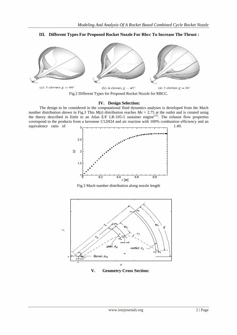
III. Different Types For Proposed Rocket Nozzle For Rbcc To Increase The Thrust :
Fig.2 Different Types for Proposed Rocket Nozzle for RBCC.
IV. Design Selection: The design to be considered in the computational fluid dynamics analyses is developed from the Mach
number distribution shown in Fig.3 This M(z) distribution reaches Me = 2.75 at the outlet and is created using
the theory described in Etele to an Atlas E/F LR-105-5 sustainer engine[11]
. The exhaust flow properties
correspond to the products from a kerosene C12H24 and air reaction with 100% combustion efficiency and an
equivalence ratio of 1.49.
Fig.3 Mach number distribution along nozzle length
V. Geometry Cross Section:

Modeling And Analysis Of A Rocket Based Combined Cycle Rocket Nozzle
www.iosrjournals.org 3 | Page
Fig.4 Geometry Cross Section.
Table 1. Geometry reference values for the sensitivity analysis.
Input Variable Value Input Variable Value
450
g
th
z
r 9.5
g
th
r
r 6.5
e 20
g 200
e
th
r
r 10
0
f
th
r
r 2.5
e 440
Table2. Input geometry variables for selected design.
Variable Value Variable Value
rth[m] 0.0551 ze[m] 0.9
rf[m] 0.17 zg[m] 0.5
rg[m] 0.37 re[m] 0.5
ψ g 17.6◦ ψe 44.5◦
φe 1◦
VI. Computational Implementation
A. The Geometry designs and Meshing were made in ICEM CFD 13.0.
B. Analyses is carried out in FLUENT 13.0
VII. Fluid Properties The reference values for enthalpy href and entropy sref are with respect to a pressure of 1[atm]
and temperature of 298 [K] and are non-zero because the Fluid mixture considers the products of a C12H24/air
reaction. Products by molar fractions consist of 13% carbon dioxide, 13% water vapour, 73.4% nitrogen, and
0.6% of unburned C12H24 hydrocarbon.
VIII. Boundary Conditions For the computations presented throughout this thesis, the throat surface is specified as an inlet boundary
condition. A uniform flow with V = 1114m/s acting normal to the throat cross section is used. This value
equates to M = 1.05 and is used instead of M = 1 to avoid potential shock wave issues due to the fact that the
flow at the throat is within the transonic range. Static pressure and total temperature P = 2577 [kPa] and T0
=3668 [K] are specified as the two remaining throat parameters.
IX. Calculations

Modeling And Analysis Of A Rocket Based Combined Cycle Rocket Nozzle
www.iosrjournals.org 4 | Page
Speed of Sound depends on temperature and can be calculated using the following formula:
θ+273.15 θc=331.5 =331.5 1+
273.15 273.15 θ in
oc
By using above formula
Speed of Sound has been calculated as 1060.95 m/sec. For Mach Number 1.05, Velocity at nozzle throat
has
been calculated as 1114 m/sec.
X. To Determine The Best Design Option Configuration From (3clover, 4clover And 5
Clover)
Fig.5 shows rocket nozzle with 3 clovers Fig.6 shows rocket nozzle with 4 clovers
Fig.7 shows rocket nozzle with 5 clovers
XI. The Below Figs Shows 3, 4 And 5 Clovers/Gates Rocket Nozzle After Meshing.
Fig.8 shows rocket nozzle with 3 clovers Fig.9 shows rocket nozzle with 4 clovers

Modeling And Analysis Of A Rocket Based Combined Cycle Rocket Nozzle
www.iosrjournals.org 5 | Page
Fig.10 shows rocket nozzle with 5 clovers
Fig.11 Streamlines for 3 clover nozzle
If you observe the above figures the streamlines across nozzle for 3 clovers are not well streamlined
clearly shown in Fig 11. Due to this randomness behavior of streamlines and vortex flows it affects the pressure
and velocity distribution across the nozzle.
Fig.12 Streamlines for 5 clover nozzle.
If you observe the above figures the streamlines across nozzle for 5 clovers are some that streamlined
clearly shown in Fig 12 as compared to 3 clover nozzle.
Fig.13 Streamlines for 4 clover nozzle
Modeling And Analysis Of A Rocket Based Combined Cycle Rocket Nozzle
www.iosrjournals.org 6 | Page
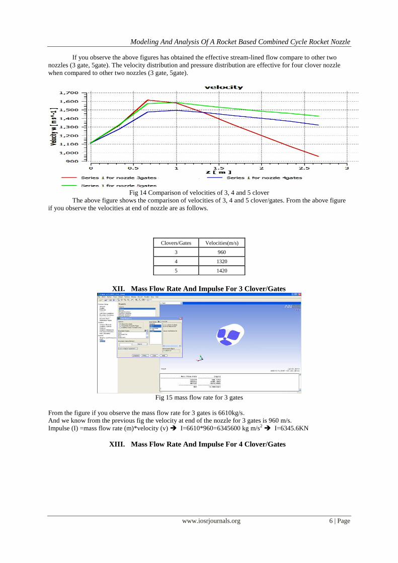
If you observe the above figures has obtained the effective stream-lined flow compare to other two
nozzles (3 gate, 5gate). The velocity distribution and pressure distribution are effective for four clover nozzle
when compared to other two nozzles (3 gate, 5gate).
Fig 14 Comparison of velocities of 3, 4 and 5 clover
The above figure shows the comparison of velocities of 3, 4 and 5 clover/gates. From the above figure
if you observe the velocities at end of nozzle are as follows.
XII. Mass Flow Rate And Impulse For 3 Clover/Gates
Fig 15 mass flow rate for 3 gates
From the figure if you observe the mass flow rate for 3 gates is 6610kg/s.
And we know from the previous fig the velocity at end of the nozzle for 3 gates is 960 m/s.
Impulse (I) =mass flow rate (m)*velocity (v) I=6610*960=6345600 kg m/s2 I=6345.6KN
XIII. Mass Flow Rate And Impulse For 4 Clover/Gates
Clovers/Gates Velocities(m/s)
3 960
4 1320
5 1420

Modeling And Analysis Of A Rocket Based Combined Cycle Rocket Nozzle
www.iosrjournals.org 7 | Page
Fig 16 mass flow rate for 4 gates
From the figure if you observe the mass flow rate for 4 gates is 6457kg/s
And we know from the previous fig the velocity at end of the nozzle for 4 gates is 1320 m/s
Impulse (I) =mass flow rate (m)*velocity (v) I=6457*1320=8523240 kgm/s2 I=8523.2KN
XIV. Mass Flow Rate And Impulse For 5 Clover/Gates
Fig 17 mass flow rate for 5 gates
From the figure if you observe the mass flow rate for 5 gates is 5842kg/s
And we know from the previous fig the velocity at end of the nozzle for 5 gates is 1420 m/s
Impulse (I) =mass flow rate (m)*velocity (v) I=5842*1420=8295640 kgm/s2 I=8295.6KN
XV. Discussion On Nozzles
1. Nozzle with 3 gates: In this nozzle, due to larger space of the gates, the mass flow rate and velocity attained by the nozzle
are 6610kg/s and 960m/s. The velocity attained by the nozzle is lower than as compared to the other two
nozzles, and the Impulse in 3clovers/gates is 6345.6KN is also lower than as compared to the other two nozzles,
and the streamlines are not well streamlined. Hence it is not suggested.
2. Nozzle with 4 gates: In this nozzle, the streamlines across nozzle and pressure distribution and velocity are moderate. This
nozzle obtained the effective stream-lined flow compared to other two nozzles. The velocity drop is also
moderate. The mass flow rate and velocity attained by the nozzle are 6457kg/s and 1320m/s, and the Impulse in
4clovers/gates is 8523.2KN is greater than as compared to the other two nozzles, Vortex flows are less. It is one
of the suggested and effective designs of the nozzle.
3. Nozzle with 5 gates: In this nozzle, the velocity distribution and pressure distribution are as effective as four gate nozzle.
The mass flow rate and velocity attained by the nozzle are 5842kg/s and 1420m/s, and the Impulse in
5clovers/gates is 8295.6KN is lower than 4 clovers/gates. The streamlines are not well streamlined as compared
to the 4 gate nozzle.
XVI. Comparison Of Numerical Simulation To A Predefined Mach Number Distribution Of
Inviscid And Viscous Simulation.
Modeling And Analysis Of A Rocket Based Combined Cycle Rocket Nozzle
www.iosrjournals.org 8 | Page
A. INVISCID SIMULATION CFD Boundary Conditions
Fluid – Kerosene – Vapor
Chemical Formula – C12H24
Density – 7.1 Kg/m3
Thermal Conductivity -0.0178 w/m-k
For Nozzle Throat
Velocity = 1114 m/sec
Supersonic Gauge Pressure = 2475.6 K Pa (2577 Kpa – Operating Pressure (101325 Pa))
Temperature = 3668 K
For Air Intake = Pressure Inlet
For Nozzle Outlet = Pressure Outlet
Operating Pressure = 101325 Pa
Wall Temperature = 500 K
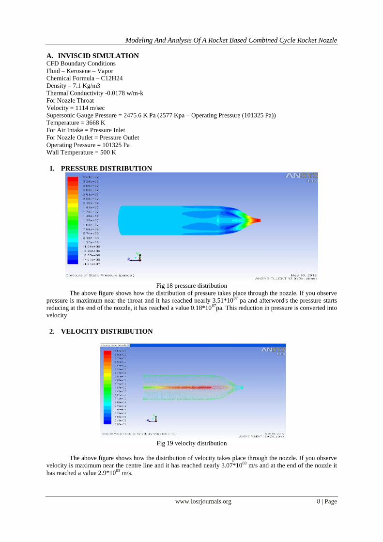
1. PRESSURE DISTRIBUTION
Fig 18 pressure distribution
The above figure shows how the distribution of pressure takes place through the nozzle. If you observe
pressure is maximum near the throat and it has reached nearly 3.51*1007
pa and afterword's the pressure starts
reducing at the end of the nozzle, it has reached a value 0.18*1007
pa. This reduction in pressure is converted into
velocity
2. VELOCITY DISTRIBUTION
Fig 19 velocity distribution
The above figure shows how the distribution of velocity takes place through the nozzle. If you observe
velocity is maximum near the centre line and it has reached nearly 3.07*1003
m/s and at the end of the nozzle it
has reached a value 2.9*1003
m/s.
Modeling And Analysis Of A Rocket Based Combined Cycle Rocket Nozzle
www.iosrjournals.org 9 | Page
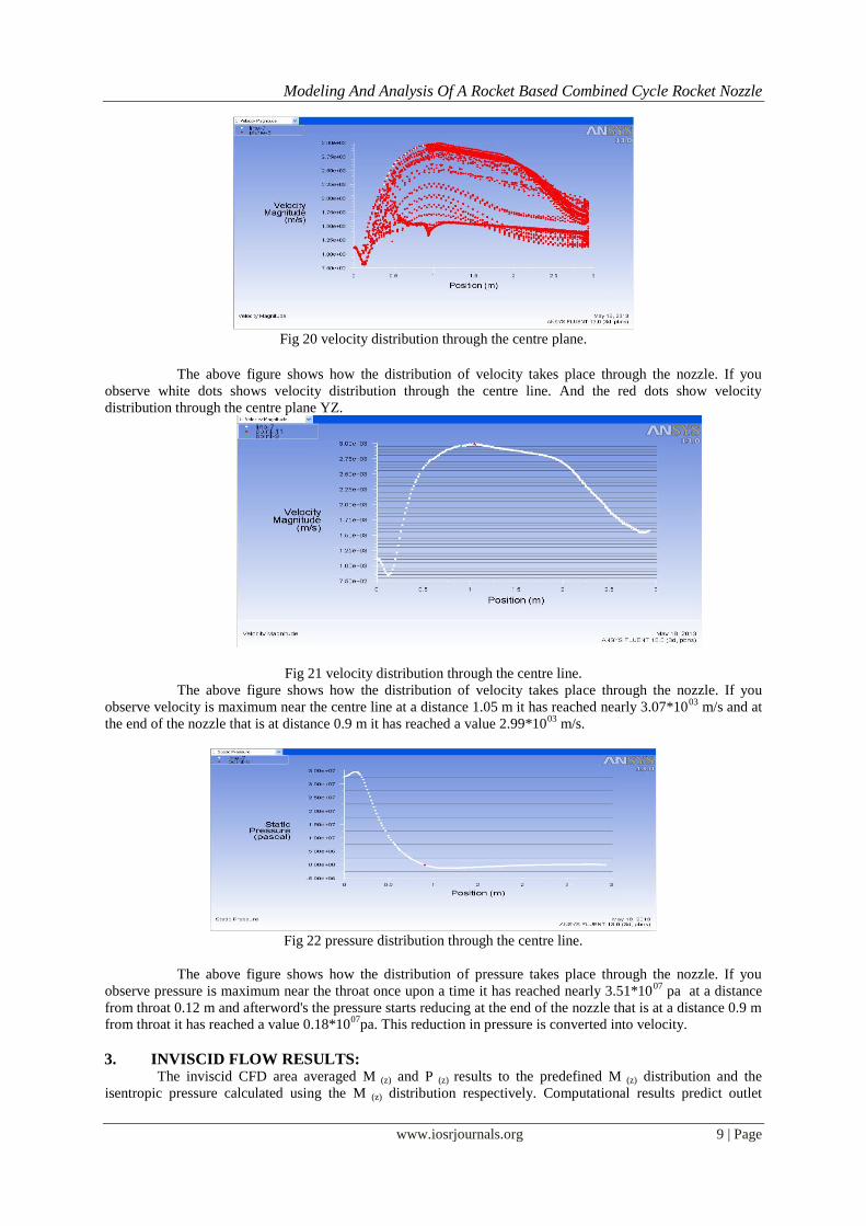
Fig 20 velocity distribution through the centre plane.
The above figure shows how the distribution of velocity takes place through the nozzle. If you
observe white dots shows velocity distribution through the centre line. And the red dots show velocity
distribution through the centre plane YZ.
Fig 21 velocity distribution through the centre line.
The above figure shows how the distribution of velocity takes place through the nozzle. If you
observe velocity is maximum near the centre line at a distance 1.05 m it has reached nearly 3.07*1003
m/s and at
the end of the nozzle that is at distance 0.9 m it has reached a value 2.99*1003
m/s.
Fig 22 pressure distribution through the centre line.
The above figure shows how the distribution of pressure takes place through the nozzle. If you
observe pressure is maximum near the throat once upon a time it has reached nearly 3.51*1007
pa at a distance
from throat 0.12 m and afterword's the pressure starts reducing at the end of the nozzle that is at a distance 0.9 m
from throat it has reached a value 0.18*1007
pa. This reduction in pressure is converted into velocity.
3. INVISCID FLOW RESULTS: The inviscid CFD area averaged M (z) and P (z) results to the predefined M (z) distribution and the
isentropic pressure calculated using the M (z) distribution respectively. Computational results predict outlet
Modeling And Analysis Of A Rocket Based Combined Cycle Rocket Nozzle
www.iosrjournals.org 10 | Page
values of Me=2.69 and pressure Pe=183.1Kpa. In comparison, the predefined M (z) gives Me=2.75 and
Pe=170.0Kpa and translate into differences of 2.1% and 7.6% respectively.
B. VISCOUS SIMULATION CFD Boundary Conditions
Fluid – Kerosene – Vapor
Chemical Formula – C12H24
Density – 7.1 Kg/m3
Thermal Conductivity -0.0178 w/m-k
Viscosity – 7 e-08 Kg/m-s
For Nozzle Throat
Velocity = 1114 m/sec
Supersonic Gauge Pressure = 2475.6 K Pa (2577 Kpa – Operating Pressure (101325 Pa))
Temperature = 3668 K
For Air Intake = Pressure Inlet
For Nozzle Outlet = Pressure Outlet
Operating Pressure = 101325 Pa
Wall Temperature = 500 K
K-ξ Turbulence has been used with 5% as turbulence intensity at boundaries.
1. PRESSURE DISTRIBUTION
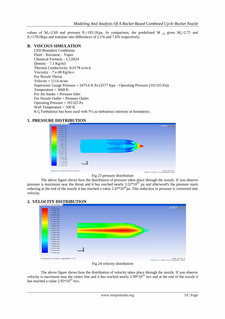
Fig 23 pressure distribution
The above figure shows how the distribution of pressure takes place through the nozzle. If you observe
pressure is maximum near the throat and it has reached nearly 3.52*1007
pa and afterword's the pressure starts
reducing at the end of the nozzle it has reached a value 2.47*1006
pa. This reduction in pressure is converted into
velocity.
2. VELOCITY DISTRIBUTION
Fig 24 velocity distribution
The above figure shows how the distribution of velocity takes place through the nozzle. If you observe
velocity is maximum near the centre line and it has reached nearly 2.99*1003
m/s and at the end of the nozzle it
has reached a value 2.95*1003
m/s.

Modeling And Analysis Of A Rocket Based Combined Cycle Rocket Nozzle
www.iosrjournals.org 11 | Page
Fig 25 velocity distribution through the centre plane.
The above figure shows how the distribution of velocity takes place through the nozzle. If you
observe white dots shows velocity distribution through the centre line. And the red dots show velocity
distribution through the centre plane YZ.
Fig 26 pressure distribution through the centre line.
The above figure shows the distribution of pressure along the nozzle. If you observe pressure is
maximum near the throat and it has reached nearly 3.50*1007
pa at a distance from throat 0.12 m and afterword's
the pressure starts reducing this reduction in pressure is converted into velocity.
Fig.27 velocity distribution through the centre line.
The above figure shows how the distribution of velocity takes place through the nozzle. If you
observe velocity is maximum near the centre line at a distance 1.05 m it has reached nearly 3.00*1003
m/s and at
the end of the nozzle that is at distance 0.9m it has reached a value 2.95*1003
m/s.
3. INVISCID FLOW RESULTS: The inviscid CFD area averaged M(z) and P(z) results to the predefined M(z) distribution and the
isentropic pressure calculated using the M(z) distribution respectively. Computational results predict outlet
values of Me=2.64 and pressure Pe= 247Kpa. In comparison, the predefined M(z) gives Me=2.75 and
Pe=170.0Kpa and translate into differences of 4% and 31.1% respectively.
XVII. Conclusion Based on the provided geometry and fluid property inputs, the present theory is capable of generating three-
dimensional diverging sections of a converging-diverging rocket nozzle.

Modeling And Analysis Of A Rocket Based Combined Cycle Rocket Nozzle
www.iosrjournals.org 12 | Page
Based on the flow analysis and impulse it is found that nozzle with 4 clovers/gates provides better results
when compared with the other i.e., 3 or 5 clovers/gates and it is one of the suggested and effective design of
the nozzle.
Results are provided for one configuration only, which is unlikely to be an optimum configuration and is
not representative of all configurations
Inviscid area-averaged computational results are within 2.1% of the predefined outlet Mach number of 2.75
and 7.6% of the isentropic pressure predicted at the outlet.
Viscous computational results obtained using the k-e turbulence model under-predict the predefined outlet
Mach number by 4% which is acceptable.
Observations from the total pressure field show that the flow does not become fully developed and that
viscous effects are contained within the boundary layers at each wall. Since the flow is not isentropic within
the boundary layer, there is corresponding pressure losses due to the increase in friction and thus a 34.9%
pressure variation at the outlet is observed when compared to the inviscid analysis.
References [1]. Turner, M. J. L., Rocket and Spacecraft Propulsion: Second Edition, Praxis Publishing Ltd., 2005.
[2]. Tajmar, M., Advanced Space Propulsion Systems, Springer-Verlag/Wien, 2003. [3]. Sutton, G. P., History of Liquid Propellant Rocket Engines, American Institute of Aeronautics and Astronautics, 2006.
[4]. Daines, R. and Segal, C., “Combined Rocket and Air breathing Propulsion Systems for Space- Launch Applications,” Journal of
Propulsion and Power, Vol. 14, No. 5, 1998, pp. 605–12. [5]. White, F. M., Fluid Mechanics, Boston: McGraw-Hill, 5th ed., 2003.
[6]. Ejector air intake design method for a novel rocket-based combined-cycle rocket nozzle by Timothy S. Waung, Carleton University
Ottawa, Ontario, Canada April 2010 [7]. Manski, D. and Hagemann, G., “Influence of Rocket Design Parameters on Engine Nozzle Efficiencies,” Journal of Propulsion and
Power, Vol. 12, No. 1, 1996, pp. 41–7.
[8]. Korst, H. H., Addy, A. L., and Chow, W. L., “Installed Performance of Air-Augmented Nozzles Based on Analytical Determination of Internal Ejector Characteristics,” Journal of Aircraft, Vol. 3, No. 6, November–December 1966, pp. 498–506.
[9]. Nayem Jahingir, M. and Huque, Z., “Design Optimization of Rocket-Based Combined-Cycle Inlet/Ejector System,” Journal of
Propulsion and Power, Vol. 21, No. 4, July–August 2005, pp. 650–5. [10]. Etele, J., Computational Study of Variable Area Ejector Rocket Flow fields, Ph.D. thesis, University of Toronto, Institute for
Aerospace Studies, Toronto, 2004.
[11]. Etele, J., Sislian, J. P., and Parent, B., “Effect of Rocket Exhaust Configurations on Ejector Performance in RBCC Engines,” Journal of Propulsion and Power, Vol. 21, No. 4, July– August 2005, pp. 656–66.
[12]. White, F. M., Viscous Fluid Flow, Boston: McGraw-Hill, 3rd ed., 2006. [13]. ANSYS, Inc., ANSYS CFX, Release 11.0 User Guide, 2006.