modeling and optimal control of hybrid uavs with wind
TRANSCRIPT

Modeling and Optimal Control of Hybrid UAVswith Wind Disturbance
Sunsoo Kim1, Niladri Das2 and Raktim Bhattacharya3
Abstract—This paper addresses modeling and control of a six-degree-of-freedom unmanned aerial vehicle capable of verticaltake-off and landing in the presence of wind disturbances. Wedesign a hybrid vehicle that combines the benefits of both thefixed-wing and the rotary-wing UAVs. A non-linear model for thehybrid vehicle is rapidly built, combining rigid body dynamics,aerodynamics of wing, and dynamics of the motor and propeller.Further, we design an H2 optimal controller to make the UAVrobust to wind disturbances. We compare its results against thatof PID and LQR-based control. Our proposed controller resultsin better performance in terms of root mean squared errors andtime responses during two scenarios: hover and level-flight.
Index Terms—Hybrid UAVs, VTOL, Aircraft Modeling, H2
Optimal Control, Wind Disturbances
I. INTRODUCTION
UNMANNED aerial vehicles (UAVs) have proved usefulfor both civil and military purposes [1]. Their popularity
is increasing in applications such as surveillance, search andrescue operations, inspections, security, aerial photograph andvideo, mapping, and cargo system management [2]–[4].
Researchers and tech companies are developing differentUASs to serve different purposes [5], [6]. We divide UAVs intotwo categories on the basis of their configurations: the rotary-wing UASs and the fixed-wing UASs. Rotary wing UAVs cantake-off,land vertically, and hover at one position [7]. Whilethey need a small space for takeoff and landing, these UAVscan neither move fast nor fly long distances since they are notenergy efficient. Compared to them, a fixed-wing of UAV ismore power-efficient, hence it can fly for a longer durationof time and for further distance [8]. Despite these advantages,fixed-wing UAVs cannot take-off and land in small spacesbecause they need a runway to do so. Our proposed hybriddesign aims to combine the advantages of the rotary-wing andthe fixed-wing design.
There are several hybrid UAV concepts [9] such as a the dualsystem (combining fixed wing and rotary-wing), the tail-sitter,and the tilt-rotor. We classify these concepts according to theirthrust direction. The simplest structure involves a dual system,which is a combination of two thrust directions: vertical andforward. In the tail sitter case, the heading of the vehicle is
1Sunsoo Kim is a Ph.D student in the Department of Electrical andComputer Engineering, Texas A&M University, College Station, TX 77843,USA. Email: [email protected]
2Niladri Das is a Ph.D student in the Department of Aerospace Engi-neering, Texas A&M University, College Station, TX 77843, USA. Email:[email protected]
3Raktim Bhattacharya is with the Faculty of Aerospace Engineer-ing, Texas A&M University, College Station, TX 77843, USA. Email:[email protected]
same as that of the thrust direction. A tail sitter vehicle takesoff vertically and then rotates pitch angle of body for the levelflight. Unlike the tail-sitter type, in a tilt rotor/wing type ofvehicle, it is the actuators that control the thrust direction. Ittakes-off, tilts the wing or rotor direction for level flight [10],[11], and lands vertically. For our research, we focus on thedual system type of UAV shown in Fig. 1. This is because thevehicle is mechanically simpler than the other hybrid UAVsand has the capability for VTOL and level flight. This UAVcan take-off and land in smaller areas while having a largerange of operation.
For the modeling of our hybrid UAV, we start with aconceptual design that satisfies our preliminary requirements.First, we calculate the forces and moments coefficients onthe wing using the vortex lattice method (VLM). After thisaerodynamic analysis, we move on to the propulsion system.Here, we experimentally gather data on the thrust and torquefrom motor-propeller pair and generate a lookup table forour final model. Next, we formulate the equations of motionsbased on rigid body dynamics. We use the detailed 3D modelof our vehicle which includes properties like mass and inertiato complete our modeling. To perform simulations on thisrigid body, we import the CAD (Computer Aided Design)model and lookup tables generated during propulsion analysisto SimScape [12]. We exploit the built-in functionality ofSimScape to import 3D design parameters and experimentaldata into the dynamic model of our UAV.
For UAV control, we mostly use the PID control methodbecause of its ease of implementation [13]–[15]. However,tuning PID gains to achieve the desired performance is a fairlychallenging problem. Experimental methods involving trialand error are used to tune these gains [16], [17]. Thus, whenUAVs encounter multiple uncertain stimuli such as wind gust,actuator noise, or just modeling errors, the controller may notwork properly. Therefore, we need a more robust controller.Researchers have developed adaptive control algorithms usingmodel identification to handle uncertainties in the inertia andmotor failure scenario [18], [19]. They have also applied therobust control methods to handle the uncertainty in the systemparameters like mass, inertia [20], and actuator characteristics[21]. However, there is little or no work on controller to rejectwind disturbances with H2 control. Therefore, in this research,we focus on a robust optimal control of our hybrid UAV, whichcan reject wind disturbance.
The paper is organized as follows. In section §II, wepresent modeling of our proposed hybrid UAV. Here, wing andthrust dynamics are presented in detail. This is followed bythe control algorithms, i.e. PID, Linear Quadratic Regulator
arX
iv:2
006.
1119
2v1
[ee
ss.S
Y]
19
Jun
2020

(LQR), and H2 control in section §III. In section §IV, weintroduce the simulation setup and show the results, followedby conclusions.
II. MODELING OF THE HYBRID UAV
In this paper, we consider both fixed and rotary wingdynamics for our hybrid UAV. We choose the flying wingshape, which does not have a tail wing as shown in Fig. 1.In this section, we are going to first discuss its design (itspayload and flight characteristics), followed by its non-lineardynamics. A linearized dynamics model is also developed atthe end of this section.
A. Aircraft Design
Aircraft design is based on the desired capabilities we spec-ify for our vehicle. Our aim is to develop a hybrid UAV whichcombines the advantages of both fixed wing and rotary wingtype UAVs. The desired capabilities of the vehicle are set fora multi-functional application and are listed in Table I. Theyencompass that which is required broadly for applications suchas drone deliveries, air surveillance and aerial photography,etc. We start with an initial configuration. This configuration
TABLE IVEHICLE DESIRED CAPABILITIES
Type of operation VTOL Growth weight 3.2 kg
Flight time 30 min Range 3 km
Level flight speed 22 m/s Flight control Auto Flight
is able to sustain level flight, desired range, and satisfy payloadcharacteristics. The final design of our UAV is selected afteraerodynamic analysis of the initial configuration and throughsuccessive iterations of analysis.
Aerodynamic stability analysis of the initial hybrid UAVconfiguration is an important step. We used a numericalmethod called Vortex lattice method (VLM). This is auniversity-level technique used in computational fluid dynam-ics, which aids in the early stages of aircraft design. In thiswork, AVL (Athena Vortex Lattice) [22], [23] and XFLR5 [24]softwares are used to implement VLM. This numerical methodmodels a wing, the primary lifting surface, as an unboundedthin sheet of discrete vortices and calculates the induceddrag and lift coefficients. It is also capable of calculatingthe air profile around an arbitrary wing with its rudimentaryconfiguration alone.
For our UAV, we create batch codes and check the stabilityof our preliminary designs, followed by calculating forces andmoments coefficients. One can see in Fig. 1 that our UAVdoes not have a tail wing, for the ease of manufacturing.Hence, achieving longitudinal stability turns out to be the mostchallenging aspect of our design iterations. To address thisproblem, we select the re-flexed airfoil, Martin Hepperle (MH)45 [25] and place the center of gravity (CG) in front of theneutral point (NP). The optimal CG point is finally fixed. Thecorresponding level flight speed characteristics are shown inTable II.
For other payloads, we place the flight controller over theCG of the vehicle. The flight controller consists of an IMU (In-ertial Measurement Unit) with integrated 3 axes accelerometerand gyroscope to measure accelerations and angular velocities.A telemetry radio for communication, RC receivers for manualcontrols, and a 6-cell LIPO battery for the power supplyare placed in the vehicle. To ensure both hover flight andlevel flight, four propellers with a diameter of 9 inch andone propeller with a diameter 12 inch are chosen, whichare rotated by 1100 (kv) brush-less-electric motors. In thefollowing subsection, we are going to first develop the rigid-body dynamics followed by modeling the wing dynamics andthe thrust dynamics, which are then all combined to generatethe full non-linear model for our proposed UAV.
TABLE IIWING CONFIGURATION
Wing span (b) 120 cm Wing area (S) 3360 cm2
Root chord (Cr) 28 cm Mean Aerodynamics Chord 21.2 cm
Tip chord (Ct) 15 cm XCG 15 cm
Sweep angle 25 ◦ Height of winglet 15 cm2
B. Rigid body dynamics modeling
We used Newton-Euler equations to develop the rigid bodydynamics of the UAV. The 6-DoF dynamic model is shown inFig. 1 with the inertial frame (Ix, Iy , Iz) and body frame (Bx,By , Bz) which follow the North-East-Down (NED) coordinatesystem. φ, θ, ψ are the Euler angles in the inertial frame, and
Fig. 1. Hybrid UAV configuration
p, q, r are angular velocities in the body frame about each axis.These 6 variables are the states for the rotational motion of theUAV. Similarly, x, y, z are the position in the inertial frame,and u, v, w are velocities in the body frame about each axis.These 6 variables are states for translational motion. Hence atotal of 12 states of the vehicle dynamics are defined as
x := [x y z u v w φ θ ψ p q r]T .
C. Wing dynamics modeling
The VLM is used to generate the aerodynamic coefficientof the wing body. The vortex lattice methods are based onsolutions to Laplaces Equation. Although VLM is a classical

method in computational fluid dynamics, it can derive quiteaccurate results of aerodynamics for 3D Lifting surface, espe-cially, in subsonic flow which we are concerning for modeling[26]. The VLM calculations are mainly processed with theboundary condition and Kutta-Joukowski theorem [27]. Thewing is discretized to small panels as Fig. 2. Vortices areplaced on each panel and the corresponding strength Γi isobtained to satisfy the boundary condition theorem. Finally,forces and moments are computed by the Kutta-Joukowskitheorem, which are presented as
Li = ρV∞ × Γi∆bi (Lift of the panel i), (1a)
L =
N∑i=1
Li (Lift of the Wing) (1b)
Di = ρV∞ × Γi∆bi (Drag of the panel i), (1c)
D =
N∑i=1
Di (Drag of the Wing) (1d)
where, ρ is the air density, V∞ is the free stream velocity, Γi isthe vortex strength in panel i, and b is the length of the vortexsegment along the quarter-chord line. The AVL software is
Fig. 2. The vortex lattice method panel
used to obtain the aerodynamic variables of the wing. Theresult sets, which depend on seven input variables, are madeup of a look-up table. The seven input factors are as follows:angle of attack, side slip angle, roll/pitch/yaw rate, elevator,and aileron deflection angle. One of the aerodynamic resultsfrom AVL is shown in Fig. 3. The resulting coefficients arethen used to calculate the forces and moments for each bodyaxis using
Fx = q∞SCFy , Fy = q∞SCFy , Fz = q∞SCFz , (2a)Mx = q∞SCMx , My = q∞SCMy , Mz = q∞SCMz , (2b)
where q∞the dynamic pressure is q∞ = 12ρV
2∞.
-2 0 2 4 6 8 10
AoA (degree)
-0.6
-0.5
-0.4
-0.3
-0.2
-0.1
0
0.1
Cz
-2 0 2 4 6 8 10
AoA (degree)
-0.3
-0.2
-0.1
0
0.1
0.2
0.3
My
Fig. 3. Aerodynamic coefficient CZ and MY : angle of attack varies from0 to 10 ◦.
D. Thrust dynamic modelingSince the hybrid UAV is intended to perform level flights,
free stream velocity should be considered when the thrust andtorque of propellers are derived. Conventionally, DC motorparameter identification and blade element theory [28] areapplied to get dynamic model. However, for more accuratemodeling, we use the experimental method to derive brushlessDC motor and propellers performance data, wind tunel testdata [29], and generate lookup tables. The result of experimenton brushless DC motor with varying pulse width modulation(PWM) signal input is shown in Fig. 4. The results of thrustand torque from the propeller 12 × 6 SF (Slow Flight) thatdepend on wind velocity acting on the wing (free streamvelocity) and RPM of motor are shown in Fig 5.
Fig. 4. The motor RPM result from the experiment with motor
0 5 10 15 20 25 30 35 40 45
Air speed (m/s)
0
10
20
30
40
50
60
Thr
ust (
N)
Propeller 12x6 SF
RPM 1000
RPM 2000
RPM 3000
RPM 4000
RPM 5000
RPM 6000
RPM 7000
RPM 8000
RPM 9000
RPM 10000
Fig. 5. The propeller thrust from the propeller performance data
E. Final non-linear modelOur hybrid vehicle is developed as a 3D model using CAD.
This 3D model which include mass, inertia, and coordinate in-formation is imported to Simscape software in Simulink [12].The final non-linear 3D model is constructed by combiningwing, motor, and propeller dynamics which are previouslydiscussed as shown in Fig. 6. This is the rapid modelingrepresenting the equations of motion of UAVs.
F. Linearized modelWe linearize the non-linear model of our hybrid UAV. Our
aim is to design the controller for the attitude control during
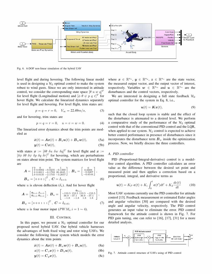
Fig. 6. 6-DOF non-linear simulation of the hybrid UAV
level flight and during hovering. The following linear modelis used in designing a H2 optimal control to make the systemrobust to wind gusts. Since we are only interested in attitudecontrol, we consider the corresponding state space [θ u w q]T
for level flight (Longitudinal motion) and [φ θ ψ p q r]T forhover flight. We calculate the linearized dynamics separatelyfor level flight and hovering. For level flight, trim states are:
p = q = r = 0, V∞ = 22.49m/s, (3)
and for hovering, trim states are
p = q = r = 0, u = v = w = 0. (4)
The linearized error dynamics about the trim points are mod-eled as
x(t) = Ax(t) + Buu(t) + Bww(t), (5a)y(t) = Cx(t), (5b)
with states x := [δθ δu δw δq]T for level flight and x :=[δφ δθ δψ δp δq δr]T for hovering, which are perturbationson states about trim point. The system matrices for level flightare
A =
[0 0 0 10 0.0002 −0.0235 −0.13600 0.0011 −0.1793 20.48450 0.0135 −2.1745 −3.2657
], Bu =
[0
0.0009−0.0407−0.6544
],
Bw = [ 0 0 0 1 ]T, C = I4×4, (6)
where u is elevon deflection (δe). And for hover flight
A =[03×3 I3×3
03×3 03×3
], Bu =
[03×4
−153.5 153.5 153.5 −153.536.9 −37.1 36.9 −37.1−1.8 −1.8 1.8 1.8
],
Bw = [ 0 0 0 1 1 1 ]T, C = I6×6, (7)
where u is four motor input (PWMi, i = 1 ∼ 4).
III. CONTROL
In this paper, we present a H2 optimal controller for ourproposed novel hybrid UAV. Our hybrid vehicle harnessesthe advantages of both fixed wing and rotor wing UAVs. Weconsider the following linear system which models the errordynamics about the trim points
x(t) = Ax(t) + Bww(t) + Buu(t), (8a)z(t) = Czx(t) + Duu(t), (8b)y(t) = Cyx(t), (8c)
where x ∈ Rnx , y ∈ Rny , z ∈ Rnz are the state vector,the measured output vector, and the output vector of interest,respectively. Variables w ∈ Rnw and u ∈ Rnu are thedisturbances and the control vectors, respectively.
We are interested in designing a full state feedback H2
optimal controller for the system in Eq. 8, i.e.,
u(t) = Kx(t), (9)
such that the closed loop system is stable and the effect ofthe disturbance is attenuated to a desired level. We performa comparative study of the performance of the H2 optimalcontrol with that of the conventional PID control and the LQR,when applied to our system. H2 control is expected to achievebetter control performance in presence of disturbances since itincorporates the disturbance term Bw inside the optimizationprocess. Now, we briefly discuss the three controllers.
A. PID controller
PID (Proportional-Integral-derivative) control is a model-free control algorithm. A PID controller calculates an errorvalue as the difference between the desired set point andmeasured point and then applies a correction based on aproportional, integral, and derivative terms as
u(t) = KP e(t) +Ki
∫ t
0
e(t′)dt′ +Kdde(t)
dt(10)
Most UAV systems currently use the PID controller for attitudecontrol [13]. Feedback measurement or estimated Euler anglesand angular velocities [30] are compared with the desiredangle and angular velocity, respectively. The PID controlgenerates an input value to eliminate the error. PID controlframework for the attitude control is shown in Fig. 7. ForPID gain tuning, one can refer to [16], [17], [31] for a moredetailed analysis.
Fig. 7. Attitude control structure of UAVs using of PID control

B. LQR optimal control
The linear quadratic regulator (LQR) is a method used indetermining the state feedback controller u = KLQRx. Thiscontroller is designed to minimize the cost function, J , definedas
J =
∫ ∞0
(xTQx + uTRu)dt (11)
where Q ≥ 0 and R > 0 are symmetric weighting matrices.These matrices are the main design parameters for defining thethe control objective so that the state error and control energyis minimized. This cost function is solved with MATLABfunction lqr(). The LQR problem can be converted to theLMI (Linear Matrix Inequality) form as given by the followingtheorem.
Theorem 1 ( [32]): The following two statements areequivalent:
1) A solution KLQR to the LQR controller exists.2) ∃ a matrix Y , a symmetric matrix W , and a symmetric
matrix Y = P−1 such that:
AY + Y AT + W TBTu + BuW + Y QY + W TRW < 0
(12)
The optimal LQR control gain, KLQR, is determined bysolving the following optimization problem.
minP ,W ,Y
trace (P ) subject to (12).
The gain KLQR is recovered by KLQR = WY −1.This optimal gain minimizes the cost function (11). To solvethis optimized solution, we used CVX [33] and MATLAB toolbox [34].
C. H2 Optimal Control
With the linear system (8) and control law (9), the H2
control closed-loop has the following form,
x(t) = (A + BuK)x(t) + Bzw(t), (13a)z(t) = (Cz + DuK)x(t), (13b)
Therefore, the influence of the disturbance w on the outputz is determined in frequency domain as z = Gzw(s)w(s)where Gzw(s) is the transfer function from the disturbance wto the output z given by
Gzw(s) = Cz(Cz + DuK)[sI − (A + BuK)]−1Bw.(14)
The problem of H2 optimal control design is then, given asystem (14) and a positive scalar γ, find a matrix K = KH2
such that
‖Gzw(s)‖2 < γ. (15)
where ‖G(.)‖2 is the corresponding 2-norm of the system. Theformulation to obtain KH2
is given by the following theorem.Theorem 2 ( [32], [35], [36]): The following two statements
are equivalent:1) A solution KH2
to the H2 controller exists.
2) ∃ a matrix W , a symmetric matrix Z, and a symmetricmatrix X such that:
AX + BuW + (AX + BuW )T + BwBTw < 0[
−Z CzX + DzW∗ −X
]< 0
trace(Z) < γ2 (16)
The minimal attenuation level γ is determined by solving thefollowing optimization problem
minW ,X,Z
γ subject to (16).
The H2 optimal control gain is recovered by KH2= WX−1.
This optimal gain ensures that the closed-loop system isasymptotically stable and attenuates the disturbance. To solvethis optimization problem, we use CVX [33] and Matlab toolbox [34]. LQR and H2 control framework for the attitudecontrol is shown in Fig. 8.
Fig. 8. Attitude control structure of UAVs using LQR and H2 controller
IV. RESULTS
A. Simulation set up
The proposed H2 optimal control is applied to attitudecontrol of the linearized dynamics of our UAV as modeled byEq. 5. We compare its performance with the PID controller andLQR. The comparison is done with respect to the control input,system response, and the amount of wind disturbance rejec-tion, in a Simulink based simulation environment, as shown inFig. 10. In this simulation, the Dryden wind turbulence modelwas used to generate the wind disturbance. The generated winddisturbance is 10 m/s from north. Angular velocity componentsof the wind along X and Y axes are shown in Fig. 9. The
0 2 4 6 8 10 12 14 16 18 20
Time (s)
-0.3
-0.2
-0.1
0
0.1
0.2
0.3
Win
d ve
locit
y (ra
d/s)
0 2 4 6 8 10 12 14 16 18 20
Time (s)
-0.1
-0.05
0
0.05
0.1
0.15
0.2
0.25
Win
d v
eloc
ity (r
ad/s
)
Fig. 9. Angular velocity component of wind disturbance about the X (Left)and Y (Right) axis generated by the Dryden wind turbulence model in theSimulink software.
final simulation environment which includes the UAV system,controller, and disturbance model is shown in Fig. 10.
We simulated two cases: Case I – Level flight (Longitudinalmotion) which considers parameters in Eq. (6) for level flighttrim states in Eq. (3). Input of the system is deflection angle ofelevon surface and measurement is angular velocity q. Initialdeviation of angular velocity about Y axis in body frame p, is0.5 rad/sec. Case II– Hover flight which consider parameters

Fig. 10. 6-DOF non-linear simulation of the hybrid UAV with disturbance
in Eq. (7) for hover at trim states in Eq. (4). Input to thesystem is the PWM signals of four motors and, measurementare all state, Euler angle and angular velocity. Initial deviationof pitch angle θ, is 10◦.
LQR (12), PID (10), and H2 (16) controllers are designedwith these two linearized systems and then tested in the non-linear model in Fig 10.
B. Simulation results
We examine the performance of the H2 control by compar-ing it with that of the PID controller and LQR in terms of rootmean squared (RMS) error and time response.
Case I: Level flight – The simulation results for theproposed H2 control, the PID, and the LQR are shown in Fig.11 and TABLE III. The proposed H2 control has the leastRMS error than the other controllers, as shown in TABLE III.The time response and overshoot of H2 control is noted to beshorter than one of the PID controller and the LQR.
0 0.5 1 1.5 2 2.5 3
Time (s)
-0.2
0
0.2
0.4
An
gu
lar
rate
(ra
d/s
)
Output: Angular rate about Y axis
LQR
PID
H2
0 0.5 1 1.5 2 2.5 3
Time (s)
0
5
10
Ele
va
tor
(de
gre
e)
Input: Elevator deflection
LQR
PID
H2
Fig. 11. Error comparison of LQR, PID, and H2 control with winddisturbance in level flight
TABLE IIIRMS ERROR FOR LEVEL FLIGHT: CASE I.
Algorithm LQR PID H2
q (rad/sec) 0.0573 0.0859 0.0457
Case II: Hover flight – The simulation results for theproposed H2 control, PID, and the LQR are shown in Fig.12 and TABLE IV. The proposed H2 control has the least
RMS error compared to the other controllers, as shown inTABLE IV, especially in yaw angle (ψ). The time responseof proposed H2 control is comparable with one from the PIDcontroller and LQR. Here, note that H2 is implicitly a betteralgorithm to deal with disturbance since it include disturbanceas a design factor.
0 2 4 6 8 10 12 14 16 18 20
Time (s)
-4
-2
0
2
4
Angle
(degre
e)
Phi
LQR
PID
H2
0 2 4 6 8 10 12 14 16 18 20
Time (s)
-5
0
5
10
Angle
(degre
e)
Theta
LQR
PID
H2
0 2 4 6 8 10 12 14 16 18 20
Time (s)
-5
0
5
10
Angle
(degre
e)
Psi
LQR
PID
H2
Fig. 12. Error comparison of LQR, PID, and H2 control with winddisturbance in Hover flight
0 5 10 15 20
Time (s)
1200
1400
1600
PW
M
Motor 1
LQR
PID
H2
0 5 10 15 20
Time (s)
1200
1400
1600
PW
M
Motor 2
LQR
PID
H2
0 5 10 15 20
Time (s)
1000
1200
1400
1600
PW
M
Motor 3
LQR
PID
H2
0 5 10 15 20
Time (s)
1000
1200
1400
1600P
WM
Motor 4
LQR
PID
H2
Fig. 13. Input comparison of LQR, PID, and H2 control with winddisturbance in hover flight
TABLE IVRMS ERROR FOR THE HOVER FLIGHT: CASE II.
Algorithm Roll angle (◦) Pitch angle (◦) Yaw angle (◦)
LQR 0.8964 1.9441 3.0217
PID 0.0349 1.3169 5.7745
H2 0.1878 1.5935 0.4370
V. CONCLUSION
This paper presents an approach to design a vertical take-off and landing hybrid UAV. We elaborately describe itsmodeling and controller design that will make it robust towind disturbances. We discuss methods that rapidly imple-ments the modeling of our proposed hybrid UAV satisfyingthe requirements with sufficient accuracy. We also propose

a robust controller based on H2 optimal theory for ourhybrid UAV. This controller achieves better performance whilerejecting wind gusts compared to that of the PID and the LQRcontroller. For the future work, discrete time system of UAVwill be developed and tested in physical UAV model.
REFERENCES
[1] Shiva Ram Reddy Singireddy and Tugrul U Daim. Technology roadmap:Drone delivery–amazon prime air. In Infrastructure and TechnologyManagement, pages 387–412. Springer, 2018.
[2] US Army. Unmanned aircraft systems roadmap 2010–2035. US ArmyUAS Center of Excellence, Fort Rucker, Alabama, USA, 10:205, 2010.
[3] Luca Canetta, Gianpiero Mattei, and Athos Guanziroli. Exploringcommercial uav market evolution from customer requirements elicitationto collaborative supply network management. In 2017 InternationalConference on Engineering, Technology and Innovation (ICE/ITMC),pages 1016–1022. IEEE, 2017.
[4] Micha Mazur, A Wisniewski, and J McMillan. Pwc global report on thecommercial applications of drone technology. PricewaterhouseCoopers,tech. Rep., 2016.
[5] Hazim Shakhatreh, Ahmad H Sawalmeh, Ala Al-Fuqaha, Zuochao Dou,Eyad Almaita, Issa Khalil, Noor Shamsiah Othman, Abdallah Khreishah,and Mohsen Guizani. Unmanned aerial vehicles (uavs): A survey on civilapplications and key research challenges. IEEE Access, 7:48572–48634,2019.
[6] Chun Fui Liew, Danielle DeLatte, Naoya Takeishi, and Takehisa Yairi.Recent developments in aerial robotics: A survey and prototypesoverview. arXiv preprint arXiv:1711.10085, 2017.
[7] Hossein Bolandi, Mohammad Rezaei, Reza Mohsenipour, Hossein Ne-mati, and S. M. Smailzadeh. Attitude control of a quadrotor with opti-mized PID controller. Intelligent Control and Automation, 04(03):335–342, 2013.
[8] Andrei Dorobantu, Austin Murch, Berenice Mettler, and Gary Balas.System identification for small, low-cost, fixed-wing unmanned aircraft.Journal of Aircraft, 50(4):1117–1130, 2013.
[9] Adnan S Saeed, Ahmad Bani Younes, Chenxiao Cai, and Guowei Cai.A survey of hybrid unmanned aerial vehicles. Progress in AerospaceSciences, 98:91–105, 2018.
[10] Burak Yuksek, Aslihan Vuruskan, Ugur Ozdemir, MA Yukselen, andGokhan Inalhan. Transition flight modeling of a fixed-wing vtol uav.Journal of Intelligent & Robotic Systems, 84(1-4):83–105, 2016.
[11] C. Hancer, K. T. Oner, E. Sirimoglu, E. Cetinsoy, and M. Unel. Robusthovering control of a quad tilt-wing UAV. In IECON 2010 - 36th AnnualConference on IEEE Industrial Electronics Society. IEEE, nov 2010.
[12] MATLAB. Simscape, 2020. [Accessed: 25-Marv-2020].[13] Yibo Li and Shuxi Song. A survey of control algorithms for quadrotor
unmanned helicopter. In 2012 IEEE Fifth International Conference onAdvanced Computational Intelligence (ICACI), pages 365–369. IEEE,2012.
[14] Atheer L Salih, M Moghavvemi, Haider AF Mohamed, and Kha-laf Sallom Gaeid. Modelling and pid controller design for a quadrotorunmanned air vehicle. In 2010 IEEE International Conference onAutomation, Quality and Testing, Robotics (AQTR), volume 1, pages1–5. IEEE, 2010.
[15] Nguyen Xuan-Mung and Sung-Kyung Hong. Improved altitude controlalgorithm for quadcopter unmanned aerial vehicles. Applied Sciences,9(10):2122, 2019.
[16] Gaopeng Bo, Liuyong Xin, Zhang Hui, and Wanglin Ling. Quadrotorhelicopter attitude control using cascade pid. In 2016 Chinese Controland Decision Conference (CCDC), pages 5158–5163. IEEE, 2016.
[17] Pengcheng Wang, Zhihong Man, Zhenwei Cao, Jinchuan Zheng, andYong Zhao. Dynamics modelling and linear control of quadcopter.In 2016 International Conference on Advanced Mechatronic Systems(ICAMechS), pages 498–503. IEEE, 2016.
[18] Matthias Schreier. Modeling and adaptive control of a quadrotor. In2012 IEEE international conference on mechatronics and automation,pages 383–390. IEEE, 2012.
[19] Zachary T Dydek, Anuradha M Annaswamy, and Eugene Lavretsky.Adaptive control of quadrotor uavs: A design trade study with flight eval-uations. IEEE Transactions on control systems technology, 21(4):1400–1406, 2012.
[20] Shafiqul Islam, Peter X Liu, and Abdulmotaleb El Saddik. Robust con-trol of four-rotor unmanned aerial vehicle with disturbance uncertainty.IEEE Transactions on Industrial Electronics, 62(3):1563–1571, 2014.
[21] Hao Liu, Xiafu Wang, and Yisheng Zhong. Quaternion-based robustattitude control for uncertain robotic quadrotors. IEEE Transactions onIndustrial Informatics, 11(2):406–415, 2015.
[22] Mark Drela and Harold Youngren. Athena vortex lattice. SoftwarePackage, Ver, 3, 2004.
[23] Tomas Melin. A vortex lattice matlab implementation for linearaerodynamic wing applications. Royal Institute of Technology, Sweden,2000.
[24] Andre Deperrois. Xflr5 analysis of foils and wings operating at lowreynolds numbers. Guidelines for XFLR5, 2009.
[25] Michael S Selig. Uiuc airfoil data site, 1996.[26] Russell M Cummings, William H Mason, Scott A Morton, and David R
McDaniel. Applied computational aerodynamics: A modern engineeringapproach, volume 53. Cambridge University Press, 2015.
[27] Dale Anderson, Ian Graham, and Brian Williams. Aerodynamics. InFlight and Motion, pages 14–19. Routledge, 2015.
[28] John M Seddon and Simon Newman. Basic helicopter aerodynamics,volume 40. John Wiley & Sons, 2011.
[29] APC Propellers. Apc performance data, 2020. [Accessed: 25-Marv-2020].
[30] Sunsoo Kim, Vaishnav Tadiparthi, and Raktim Bhattacharya. Nonlinearattitude estimation for small uavs with low power microprocessors. arXivpreprint arXiv:2003.13802, 2020.
[31] Sunsoo Kim, Vedang Deshpande, and Raktim Bhattacharya. H2 opti-mized pid control of quad-copter platform with wind disturbance. arXivpreprint arXiv:2003.13801, 2020.
[32] Guang-Ren Duan and Hai-Hua Yu. LMIs in control systems: analysis,design and applications. CRC press, 2013.
[33] Michael Grant, Stephen Boyd, and Yinyu Ye. Cvx: Matlab software fordisciplined convex programming, 2009.
[34] Da-Wei Gu, Petko Petkov, and Mihail M Konstantinov. Robust controldesign with MATLAB®. Springer Science & Business Media, 2005.
[35] Pierre Apkarian, Hoang Duong Tuan, and Jacques Bernussou.Continuous-time analysis, eigenstructure assignment, and h/sub 2/syn-thesis with enhanced linear matrix inequalities (lmi) characterizations.IEEE Transactions on Automatic Control, 46(12):1941–1946, 2001.
[36] Stephen Boyd, Venkataramanan Balakrishnan, Eric Feron, and LaurentElGhaoui. Control system analysis and synthesis via linear matrixinequalities. In 1993 American Control Conference, pages 2147–2154.IEEE, 1993.