modeling and simulation for mission operations work system...
TRANSCRIPT
MODELING AND SIMULATION FOR MISSION OPERATIONS WORK SYSTEM DESIGN 85
Journal of Management Information Systems Spring 2003 Vol 19 No 4 pp 85ndash128
copy 2003 ME Sharpe Inc
0742ndash1222 2003 $950 + 000
Modeling and Simulation for MissionOperations Work System Design
MAARTEN SIERHUIS WILLIAM J CLANCEY CHIN SEAHJAY P TRIMBLE AND MICHAEL H SIMS
MAARTEN SIERHUIS is a senior research scientist at the Research Institute for Ad-vanced Computer Science (RIACS is an institute of the Universities Space ResearchAssociation at NASArsquos Ames Research Center) where he manages the Brahms projecton modeling and simulating work practice His research interests are multiagent mod-eling languages and their application to the development of human-centered systemsBefore joining RIACS he was a member of the Work Systems Design group and theExpert Systems laboratory of NYNEX Science amp Technology He also developedexpert systems as a senior knowledge engineer in the Netherlands and at IBM Hereceived an engineering degree in Higher Informatics from the Hague Polytechnicand his PhD from the Department of Social Science Informatics at the University ofAmsterdam
WILLIAM J CLANCEY is a senior research scientist at the Institute for Human amp Ma-chine Cognition (IHMC) University of West Florida Pensacola and chief scientistfor human-centered computing at NASArsquos Ames Research Center ComputationalSciences Division His current interest is the relation of descriptive cognitive theoriesto human experience and neural processes Before joining IHMC and NASA he wasa founding member of the Institute for Research on Learning where he codevelopedthe work system design methods of business anthropology in corporate environmentsHe also did research in artificial intelligence at Stanford Universityrsquos KnowledgeSystems Laboratory He received his PhD in computer science from Stanford Uni-versity He is a member of the steering committee of the Mars Society and serves as aNASA Visiting Researcher for the Challenger Centerrsquos school outreach program
CHIN SEAH is a computer scientist at Science Applications International Corporation(SAIC) working at NASArsquos Ames Research Center on the Brahms project He isapplying the Brahms work system design and modeling approach to MER missionoperations Before joining the Brahms team he worked as a business process man-agement consultant at Andersen Consulting and before that as a knowledge engineerat Mindbox Inc implementing rule-based expert systems He has a BS in computerscience from Santa Clara University and an MS in computer information sciencefrom the University of Pennsylvania where he did research in natural language pro-cessing and computer graphics
JAY P TRIMBLE is a computer scientist at NASArsquos Ames Research Center where he isthe Project Manager for the Mars Exploration Rover Human Centered ComputingProject and the group lead for the Ubiquitous Computing and User Centered DesignGroup His research interests are in the development and application of human cen-tered design methods for software to support collaboration in space mission systems
86 SIERHUIS ET AL
Before coming to NASA Ames he worked for nine years at the Jet Propulsion Labo-ratory where he served as Lead Operations Director for the successful Shuttle Imag-ing Radar Missions and four years at NASArsquos Johnson Space Center as a flightcontroller for space shuttle payloads He has an MS in computer science from theUniversity of Southern California and a BA in geology from UC Berkeley
MICHAEL H SIMS received a BA in Physics and a PhD in Computer Science andMathematics from Rutgers University and has been at NASArsquos Ames Research Cen-ter since 1987 His research includes robotics machine learning visualization andtools for enhancing and easing scientific modeling He was one of the founding mem-bers of the artificial intelligence group at Ames and was a founder and long-time leadof Amesrsquo Intelligent Mechanisms Group (Robotics) Dr Sims is actively involved inplans for future planetary missions including robotic activities and human settlementson Mars and the Moon He has been a past member of the advisory council to theNational Robotics Engineering Consortium and chair of NASArsquos TeleroboticsIntercenter Working Group He was a participant on the Mars Pathfinder missionPrincipal Investigator for the Victoria Lunar Proposal and is a Coinvestigator on the2003 Mars MER rover mission He is current at the NASA Amesrsquo Center for MarsExploration and the Computational Sciences Division
ABSTRACT Work system analysis and design is complex and nondeterministic Inthis paper we describe Brahms a multiagent modeling and simulation environmentfor designing complex interactions in humanndashmachine systems Brahms was origi-nally conceived as a business process design tool that simulates work practices in-cluding social systems of work We describe our modeling and simulation method formission operations work systems design based on a research case study in which weused Brahms to design mission operations for a proposed discovery mission to theMoon We then describe the results of an actual method application projectmdashtheBrahms Mars Exploration Rover Space mission operations are similar to operationsof traditional organizations we show that the application of Brahms for space mis-sion operations design is relevant and transferable to other types of business pro-cesses in organizations
KEY WORDS AND PHRASES agent languages business process modeling mission op-erations design multiagent simulation work practices
WORK SYSTEMS INVOLVE PEOPLE MACHINES tools documents and facilities inter-acting in activities over time These activities produce goods services ormdashas is thecase in the work system described in this papermdashscientific data Many work systemswe encounter every day have existed over a long period of time Improvement of suchwork systems is often done through business process analysis and reengineering [78 12] But managers must also design work systems de novo
One of the challenges of work system design is that work systems are often largeand complex and persist over a long period of time This makes the design processcomplex and nondeterministic In this paper we describe Brahms a multiagent mod-eling and simulation environment for designing complex interactions in humanndashma-chine systems
MODELING AND SIMULATION FOR MISSION OPERATIONS WORK SYSTEM DESIGN 87
Brahms was originally conceived of as a business process modeling and simulationtool that incorporates the social systems of work by illuminating how formal processflow descriptions relate to peoplersquos actual located activities in the workplace Ourresearch started in the early 1990s as a reaction to experiences with work processmodeling and simulation in the T1-order process redesign project at the NYNEX cor-poration [20] Although an effective tool for convincing management of the potentialcost savings of the newly designed T1-order process the modeling and simulationenvironment NYNEX used (Sparkstrade from Coopers amp Lybrand) was only able todescribe work as a normative workflow However the social systems uncovered inwork practices studied by the T1 design team played a significant role in how workactually got done in NYNEX organizations Multitasking informal assistance andcircumstantial work interactions could not easily be represented in a tool with a strictwork flow modeling structure In response we began to develop a tool that wouldhave the benefits of work process modeling and simulation but be distinctively able torepresent the relations of people locations systems artifacts communication andinformation content [5] In Brahms we model work processes at the work practicelevel We describe our modeling and simulation method for mission operations worksystem design based on a research case study in which we used Brahms to designmission operations for a proposed discovery mission to the Moonmdashthe Victoria Mis-sion We then describe the results of an actual method application project the BrahmsMars Exploration Rover (MER) model of the design of the mission operations worksystem of the MER robotic mission to Mars scheduled to be launched in 2003 [6 16]
Mission operations systems for space missions (robot and human) are comprised ofa complex network of human organizations information and deep-space networksystems and spacecraft hardware From the point of view of the management infor-mation systems (MIS) community one of the problems in mission operations designis how mission information systems are related to work practices From this perspec-tive space mission operations are similar to the operations of organizations that tradi-tionally are the domain of MIS research The application of Brahms for space missionoperations design is relevant and as we discuss in the conclusions section transfer-able to other types of business processes
Work Practice
THE CONCEPT OF WORK PRACTICE ORIGINATES in the research disciplines of socio-tech-nical systems business anthropology and management science Work systems designas presented here has its roots in the design of socio-technical systems This methodwas developed in the 1950s by Eric Trist and Fred Emery [10 19] to understand andleverage the advantages of the social and technical aspects of work Work systems de-sign extends this tradition focusing on both the informal and formal features of workand applying ethnography and participant observation [3 9 11 25 29 ch 16]
Work practice is defined as the collective activities of a group of people who col-laborate and communicate while performing these activities synchronously or asyn-
88 SIERHUIS ET AL
chronously Very often people view work merely as the process of transforminginput to output which is a Tayloristic view Sometimes for example when process-ing a customer order the input and output of the work is necessarily well-definedBut often it is more difficult to describe human interaction Consider a group ofscientists on a discovery mission Exploration involves physical search of a land-scape pursuing broad scientific questions not processing or searching for prefor-mulated data as in office work To describe scientific work we must consider howinstruments (often remotely controlled) create data sets and how distributed teamscollaboratively construct meaningful information
Work practice includes how people behave in specific situations at specific momentsin the real world To describe peoplersquos circumstantial behavior we need to includeecological (environmental) influences on individual activity (not only problem-solvingbehavior) such as collaboration ldquooff-taskrdquo behaviors multitasking interrupted andresumed activities informal interaction use of tools and movements [5 23]
Brahms is a modeling and simulation environment for representing work practiceusing a multiagent rule-based activity language models are simulated using the Brahmsengine This paper discusses how we are using Brahms to design the work system formission operations of robotic space missions to the Moon and Mars The attentivereader may question how we can design a work practice Indeed a work practice isnot designed but it emerges over time The question is can a model at the workpractice level be useful for the design of mission operations We hypothesize that thedetailed holistic representation of work will be especially useful for revealing prob-lems of work flow and timing that a more abstract representation of work would takefor granted [1 2 5 24]
Brahms Language
BRAHMS HAS A MULTIAGENT LANGUAGE for describing agents or objects performingactivities We will briefly explain the modeling concepts of the language For a moredetailed description of the language see Sierhuis [23] and van Hoof and Sierhuis[27] Brahms models are not necessarily as detailed as models of cognitive problem-solving (though a modeler could choose to do this) nor are they as general as func-tional models of business processes (see Figure 1)
Brahms models describe a work process at the work practice level The languageembodies assumptions about how to describe social situations workplaces and workpractice
Agents and Groups
Agents can represent individuals a group of individuals or model-based systemssuch as ldquosoftware agentsrdquo Agents can belong to multiple groups (multiple groupinheritance) such that individual behaviors are blends of different norms belief sys-tems roles and so on
MODELING AND SIMULATION FOR MISSION OPERATIONS WORK SYSTEM DESIGN 89
For example in the domain of missions operations we can represent the scienceoperations team as a single Brahms agent with the teamrsquos behavior represented by theagentrsquos ldquoindividualrdquo behavior The science operations team is actually part of a largergroup called the science team We can represent the science team as a Brahms groupwith more ldquogeneralrdquo behavior By specifying that the science operations team agent isa member of the science team group the agent will have a combined behavioralspectrum of its individual behavior plus the inherited more general science team be-havior The definition of agents and groups is completely under control of the mod-eler and thus the level at which we model agents is model-specific We could easilyrepresent ldquoJoerdquo and ldquoJoannerdquo as individual agents and members of the science opera-tions team group which in turn could be represented as a Brahms group In such amodel we represent individual team members which require more detail
Objects and Classes
Objects are representations of artifacts in the world or data objects created by informa-tion processing and so on Unlike agents objects do not behave based on their repre-sentations of the world (beliefs) but instead are directly affected by the actual worldstate (see Beliefs and Facts section) Objects can be generalized into class hierarchies
For example staying with the mission operations domain we can represent the ac-tual information flow of the ground-based work process by modeling the missionoperation software systems as well as the client-computers that the science teams usefor accessing these systems Brahms allows modeling of object-behavior in a similarway as modeling agent-behavior (see Activities section) Using objects we can modelinformation-processing behavior of software systems as well as the humanndashmachineinteraction between (human) agents (eg the science teams) and the client-comput-ers through which they are accessing the software In general intelligent agents thatact based on their mental state are represented as Brahms agents whereas purelyreactive systems and data objects are most often represented as Brahms objects
Beliefs and Facts
Brahms agents and objects represent the world state internally as propositions calledbeliefs [13 18] For example agent John believes that his car is the color greenPerhaps Mary believes that Johnrsquos car is blue Facts are actual world states and areglobal in the simulation world For example perhaps the world fact states that Johnrsquoscar is white
Figure 1 Relation of Brahms Models to Other Models
90 SIERHUIS ET AL
Agent and object beliefs and world facts are the ingredients of a Brahms model thatmake agents and objects behave over time when the model is executed in a simula-tion run During a simulation every agent and object has a belief set that can bechanged by different events communication fact detection reasoning and activityperformance Similar to Belief-Desire-Intention (BDI) agent architectures beliefs canrepresent an agentrsquos beliefs about the world desires intentions and goals Updates inan agentrsquos belief set are evaluated by the agentrsquos reasoning and work-selection engineand affect an agentrsquos reasoning state and actions [30] Object beliefs on the otherhand are not representing a mental state of objects but rather are a representation ofdata or information processing state Updates in an objectrsquos belief set are evaluated bythe objectrsquos reasoning engine representing an objectrsquos information processing capa-bility Facts are global to the simulated world though as in the real world they areonly perceivable locally As shown in Figure 2 in Brahms there is a separation be-tween the belief set of an individual agent or object and the fact set of the world beingsimulated (ie the world state)
The purpose is to give the modeler the ability to include each agentobjectrsquos ldquointer-pretationrdquo of the state of the world Brahms agents interpret facts in the world by asituated fact-detection mechanism (ie ldquodetectablesrdquo) through which agents can in-ternalize world facts as beliefs Consequently these new beliefs allow an agent to act(ie perform activities see Activities section) Comparatively objects are reactivebecause their actions are based directly on world facts
For a more complete description of how the complex agentobjectrsquos reasoning en-gine works see Sierhuis [23 ch 4]
Activities
Every agent or object behavior is represented as an activity A problem-solving task isa kind of activity but there are many other activities of different character For ex-ample reading e-mail answering the phone having lunch and browsing on the Webare activities but not usually defined as functions (tasks) and may or may not poseproblems during a personrsquos performance [4] An agentrsquos situation-dependent behav-ior is therefore modeled using activities
Brahms has an activity-based subsumption architecture by which an agentrsquos activi-ties can be decomposed into subactivities (see Figure 3) An agent engaged in a low-level activity is still performing the ldquohigher-levelrdquo activities on the activation path ofthe activity tree (eg answering the telephone during a meeting) Activities can beinterrupted and resumed just as humans can multitask by switching between differ-ent activities Activities always take time even a ldquodo nothingrdquo activity An example ofa long-term composite activity from the Victoria model is searching for water ice ina permanently dark crater While in this activity a subactivity is drilling in the lunarsurface A parent activity above the long-term activity is being on a science missionon the South Pole of the Moon
Activities are modeler-defined elements Indeed a Brahms model is the Brahmsmodelerrsquos interpretation of peoplersquos activities in practice (hence the notion of model-
MODELING AND SIMULATION FOR MISSION OPERATIONS WORK SYSTEM DESIGN 91
Figure 2 Beliefs and Facts Venn Diagram
ing work practice) The Brahms language allows for user-defined primitive and com-posite activities describing an agentrsquos behavior There are a number of predefinedprimitive activity types with predefined semantics such as communicate move cre-ate-objectagentarea and get and put Activities may also be written in the Java pro-gramming language
Primitive activities take time which may be specified by the modeler as a definitequantity or a random quantity within a range Activity duration can also be param-eterized with an agentrsquos belief (eg the agent believes a particular meeting will takean hour which is passed as a parameter at the start of the meeting activity) Howeverbecause workframes (see Workframes section) can be interrupted and never resumedwhen an activity will finish cannot be predicted from its start time Primitive activitiesare atomic behaviors that are not decomposed Whether something is modeled as aprimitive activity is a decision made by the modeler A primitive activity also has apriority that is used for determining the priority of workframes An example of aprimitive activity in Brahms source code is1
primitive-activity work-on(Order order)
display ordfWorking on an orderordm a display name
priority 10 a relative priority
random true the duration is between min and max duration
min_duration 3600 in seconds
max_duration 10800 in seconds
resources order OrderSystem resource objects needed
92 SIERHUIS ET AL
This activity specifies an agent working on a specific order (given by the parameterorder) between one and three hours It also specifies that besides needing the order towork on the agent also needs to use the order system as a resource If we were inter-ested in more detail about how the agent performs this activity we could easily de-compose the activity into a composite activity describing how the agent actually workson the order
For a more detailed description of primitive and composite activities and how theyare executed see Sierhuis [23 ch 4]
Workframes
An agent cannot always carry out all activities that are possible given the agentrsquoscognitive state and location Each activity is therefore associated with a conditionalstatement or constraint representing a conditionactivity pair most of the time re-ferred to as a rule [17 22 30] If the conditions of a rule are believed by the agentthen the associated activities are performed In Brahms such rules are calledworkframes Workframes are situation-action rules derived from production rulesbut because they execute activities they take time A workframe precondition tests abelief held by the agent An example of a workframe for an agent working on cus-tomer orders is
Figure 3 Workframe Activity Hierarchy
MODELING AND SIMULATION FOR MISSION OPERATIONS WORK SYSTEM DESIGN 93
workframe Do-Work
variables
foreach(Order) order
when (knownval(order is-assigned-to current))
do
work-on(order)
If three orders are assigned to the agent (ldquocurrentrdquo) and the agent has beliefs forthree of the orders matching the precondition Brahms creates three workframeinstantiations (wfi) of the workframe Do-Work for the agent and in each wfi theforeach variable is bound to one of the three orders and the work-on activity is ex-ecuted once for each order This means that the agent works on all three orders oneorder at a time The order in which the agent works on the three orders is indetermi-nate Besides the foreach-type variable the Brahms language includes collectall andforone respectively allowing the agent to work on all three orders at once or on justone (which one is indeterminate)
A composite activity expresses an activity that may require several activities andworkframes to be accomplished Since activities are called within the do-part (iethe body) of a workframe each is performed at a certain time within the workframeThe body of a workframe has a top-down left-to-right execution sequence Prefer-ence or relative priority of workframes can be modeled by grouping them into or-dered composite activities The workframes within a composite activity howevercan be performed in any order depending on when their preconditions are satisfied Inthis way workframes can explicitly control executions of composite activities andexecution of workframes depends not on their order but on the satisfiability of theirpreconditions and the priorities of their activities (see Figure 3)
For a more detailed description of workframes and how they are executed seeSierhuis [23]
Geography
Where people and things are located affects group performance For example thedesign of the MER mission operation building at the Jet Propulsion Laboratory (JPL)affects how long it takes for people to move from their individual offices to the con-ference room on the second floor where most of the important meetings are heldTime to move to another area is but one of the factors that influences how things getdone Other location-dependent factors include colocation or distribution of peopleand artifacts and use of communication tools
Indeed the fact that we cannot ignore the influence of location in our real-worldactivities is one of the reasons conventional workflow models do not represent workpractice The geography model in Brahms represents where activities occur hencewe speak of located behaviors Agents and objects are located in areas and can move
94 SIERHUIS ET AL
from area to area by performing a move activity Agents and objects can also carryother agents and objects using the get and put activities
The Brahms language allows for the representation of types of user-defined loca-tions (called area definitions) such as buildings rooms and offices but also locationson planets such as craters Area definitions can be represented hierarchically in a inher-itance (is-a) hierarchy Areas are specific location instances of area definitions We canrepresent a complex hierarchical geography by making areas be part of other areas(using the part-of relationship) Thus we can represent a building with floors and roomsusing the part-of relation between the areas For example the Floor-1 area can be partof Building-1 area and Room-1 area can be part of Floor-1 Then when an agent islocated in Room-1 the agent is also located in Floor-1 as well as in Building-1
Communications
Communication is a special type of activity When an agent or object communicatesit either sends or receives beliefs from other agents or objects In Brahms we arespecifically interested in what triggers an activity often it is a communication Wealso model the communication tools as located objects (eg telephones pagers)which are part of a work practice For example in both the Victoria and the MERmodel we model the communication delays to the Moon and Mars respectively aswell as the computer systems used to access and add data to the critical missionoperations systems Human-to-human communication is modeled as colocated face-to-face communication (which means that the agents have to be in the same locationto communicate) phone conversations or e-mail
Mission Operations Work System Design
THE WORK INVOLVED IN ROBOTIC SPACE MISSIONS is distributed over a number ofhuman teams and one or more robots During a mission teams of scientists space-craft engineers computer scientists and roboticists work together 24 hours a day in adedicated work environment The team of scientists headed by the principal investi-gator (PI) is responsible for deciding what science activity the robot needs to per-form Based on the science objectives for a next command cycle teams of engineersdecide on the actual command sequence to be ldquouplinkedrdquo to the robot After the robotreceives the uploaded command sequences it executes the commands At this timethe ground-based teams are monitoring the health and returned science data from therobot Different teams of engineers transform the ldquodownlinkrdquo science data into hu-man-readable form This can be in the form of three-dimensional surface imagestaken by stereographic cameras or particular scientific instrument readings from thescience ldquopayloadrdquo onboard the robot After the returned science data has been con-verted and the health of the robot confirmed the science team performs the next cycleof science decision-making based on the downlink data Thus the uplink cycle startsover again
MODELING AND SIMULATION FOR MISSION OPERATIONS WORK SYSTEM DESIGN 95
The science team is a user of the rover from the perspective that the rover is on theplanetary surface being controlled by the Earth-based science team But by virtue ofbeing peoplersquos arms and eyes on the surface and by having ldquoautonomousrdquo capabilityto carry out commands the rover is more of an assistant than a simple tool In par-ticular the work can be viewed as distributed between people and robot and we canask who is doing what where when and how
The Victoria Lunar Mission
Victoria is the name of a proposed long-term semiautonomous robotic mission to theSouth Pole region of the Moon The primary mission objective of Victoria is to verifythe presence of water ice and other volatiles within permanently shadowed regions onthe Moon This will be accomplished by gathering the necessary lunar data for ana-lyzing the history of water and other volatiles on the Moon and by implication in theinner solar system The Victoria team has decided to use a high-speed semiautono-mous rover
One of the dominating constraints in any robotic mission is power consumption Inevery activity the rover uses energy therefore the sequence of activities for the roveris constrained by the amount of power available to complete the sequence When therobotrsquos batteries are low it needs to return to a sun-exposed spot to recharge its batter-ies During the Victoria mission the rover will traverse into permanently dark regionson the Moon During these traverses the rover will use its neutron detector instrumentto detect hydrogen and the Sample Acquisition and Transfer Mechanism (SATM) todrill into the lunar surface and take surface samples to be investigated using an arrayof science instruments
A basic work system design problem is to configure the mission operations so therobotrsquos activities inside the permanent dark region are most efficient (ie consumethe least amount of energy in order to spend as much time as possible collectingscience data)
Victoria Mission Operations Work System
Figure 4 represents the work system elements and their relative location during theVictoria mission The Science Team consists of colocated sub-teams the ScienceOperations Team (SOT) the Instrument Synergy Team (IST) and the Data Analysisand Interpretation Team (DAIT) There are two other supporting teams the Data andDownlink Team (DDT) and the Vehicle and Spacecraft Operations Team (VSOT)The teams communicate with the Victoria rover on the lunar surface using the Uni-versal Space Network (USN) directly and via a lunar orbiter The flow of data fromthe rover will be dominated by contextual data and science data This data will cometo NASAAmes via the USN data connection and will be automatically converted innear real-time to accessible data formats that can be made available to the teams viadata access and visualization applications
96 SIERHUIS ET AL
Based on previous experience the mission designers hypothesized that many is-sues will affect the decision cycle of the science team one of which is data overload[26] They therefore specifically addressed the following questions in the work sys-tem design for Victoria
1 How will science data be gathered collaboratively with the Earth-based sci-ence team rover teleoperator and the rover on the lunar surface
2 How will science data be made available to the science team3 What is the effect of a particular work system design on the power consump-
tion of the rover during a science traverse into a permanent dark crater
To answer these questions we developed a model of the activities of the teams basedon the description of a planned mission traverse
Purpose of the Victoria Model
The major limitation of current robot energy modeling tools apart from model main-tenance is the inability to include human factors in the calculations of the powerconsumption of the rover Before our case study the influence of Earth-based opera-
Figure 4 Victoria Mission Operations Work System
MODELING AND SIMULATION FOR MISSION OPERATIONS WORK SYSTEM DESIGN 97
tions practice on the energy usage of the rover was unknown The purpose of the casestudy was (1) to prove that we could model this complex work system and (2) todetermine the effect of a particular work system design on the power consumption ofthe rover during a science traverse into a permanent dark crater
The model prescribes a work system design by incorporating a model of the loca-tions and movement of the rover and teams activities of all the Earth-based teamsthe rover their communication actions as well as the hardware and software systemsthat are used Next we give a brief description of the design of the Victoria worksystem For a more detailed description we refer the reader to Sierhuis [23 ch 8]
Agent Model
Figure 5 shows the group membership hierarchy on which the design of the worksystem is based The agents in the model are the Earth-based human teams and theVictoria rover as shown in Figure 4 The teams are represented as single agentsbecause at this moment it is not possible to prescribe the composition and practices ofeach team in more detail For example the ldquoplan a command sequencerdquo activity ofthe SOT represents the work of the team whereas the individual activities of eachteam member remain unspecified
The Victoria rover is modeled as an agent because it has activities including primi-tive actions that change the world movements and communications2
Table 1 shows a possible distribution of the functions over the Victoria teams [28]Details of how different teams collaborate to perform these functions constitute thework practice specified in Brahms workframes of the different agents
An example workframe for the DAIT agent is interpreting the hydrogen data beingdownlinked by the Victoria rover when it is detecting hydrogen
workframe wf_InterpretHydrogenData
variables
foreach(Data) nd
when (knownval(currentnotifyUser = interpretdata) and
knownval(VisualizationSystemneutronDetectorData = nd))
do
InterpretHydrogenData(110 nd)
conclude((currentnotifyUser = receivedhydrogendata)
The workframe states that if the DAIT agent believes that it needs to interpret sciencedata and the DAIT agent believes that the data visualization system has neutron spec-trometry data available the DAIT agent will start the interpretation of the hydrogendata Once it is done with the interpretation it believes that it has received new hydro-gen data which will make the DAIT agent communicate this information to the SOTagent (not shown)
98 SIERHUIS ET AL
Object Model
A Brahms object model consists of the classes and instances of physical artifacts aswell the data objects created during the simulation The Victoria object model shownin Figure 6 includes classes for the science instruments on the rover as well as otherobjects contained in the rover such as the carousel and the battery The data commu-nicator class includes the objects for S-band and UHF communication The modelalso represents software systems that receive convert and visualize mission dataThe Data and CoreSample classes dynamically create data instances and lunar coresample objects during the simulation
For example the uplink command for the Victoria rover contains a dynamicallycreated data object containing beliefs that represent the command sequence data be-ing uplinked
CommandSequence2 instanceof Data
(VictoriaRovernextActivity =
SearchForWaterIceInPermanentDarkAreaActivity)
(VictoriaRoversubActivity = projectsvictoriaDrillingActivity)
(SATMlengthIntoSurface = 100)
(SATMsampleVolume = 10)
In the above example the CommandSequence2 data object contains two commandsThe first command tells the rover its next activity is to search for water ice This will
Figure 5 Victoria Agent Model
MODELING AND SIMULATION FOR MISSION OPERATIONS WORK SYSTEM DESIGN 99
Tabl
e 1
Fun
ctio
nal A
ctiv
ity D
istr
ibut
ion
Ove
r Vic
tori
a Te
ams D
ata
anal
ysis
Veh
icle
and
Scie
nce
Inst
rum
ent
and
data
and
Spac
ecra
ftop
erat
ions
syne
rgy
inte
rpre
tatio
ndo
wnl
ink
oper
atio
nste
amte
amte
amte
amte
amR
over
Upl
ink
1M
aneu
ver
1C
omm
ands
for
1Lo
ng-t
erm
1Te
leco
mm
unic
atio
ns1
Man
euve
r1
Com
man
dpr
oces
sco
mm
ands
engi
neer
ing
plan
ning
for
com
man
dsco
mm
ands
exec
utio
n2
Com
man
dop
erat
ion
ofsc
ienc
e2
Com
man
dse
quen
ces
for
robo
tspa
cecr
aft
oppo
rtun
ities
sequ
ence
s fo
rex
perim
ent
2E
mer
genc
y or
expe
rimen
top
erat
ion
anom
aly
oper
atio
nre
solu
tion
com
man
dsD
ownl
ink
1M
onito
ring
of1
Dat
a qu
ality
1E
xper
imen
t dat
apr
oces
she
alth
and
asse
ssm
ent
colle
ctio
nst
atus
tele
met
ry2
Exp
erim
ent d
ata
2D
ata
proc
essi
ngfr
om r
obot
colle
ctio
nan
d en
hanc
emen
tsu
bsys
tem
s
100 SIERHUIS ET AL
put the rover in a water ice search state The second command is a sub-activity com-mand stating that the rover should start a drilling activity in which it should drill for10 cm into the lunar surface and then should take a 10cc sample (the SATM object isthe lunar surface drill on the rover)
Geography Model
The Victoria geography model shown in Figure 7 represents locations on the Earthand Moon (cf Figure 4) The dotted lines in Figure 7 show class-instance relation-ships and the solid lines show part-of relations
The Victoria teams and systems are located in Building244 the UsnDish1 satellitedish is located in the area UsnSatelliteLocation Locations for the simulated scenarioare represented on the Moon (described in the next section) ShadowEdgeOfCraterSN1represents the location of the rover at the start of the simulation (the shadow edge thatis in crater SN1) ShadowArea1InCraterSN1 represents the location in the permanentshadowed SN1 crater where the rover will perform a drilling activity The LandingSitearea is only represented for completeness
Victoria Model Simulation Results
THE SIMULATION PROVIDES VISIBILITY into the behavior of the work system overtime that is activities communication and movement of each agent and object Af-
Figure 6 Victoria Object Model
MODELING AND SIMULATION FOR MISSION OPERATIONS WORK SYSTEM DESIGN 101
ter the model is developed and compiled the Brahms simulation engine executes themodel A relational simulation history database is created including every simulationevent An end user display tool called the AgentViewer uses this database to displayall groups classes agents objects and areas in a selectable tree view The end usercan select the agents and objects he or she wants to investigate The AgentViewerdisplays a workframe-activity hierarchy time line of the agents and objects selectedoptionally showing agent and object communications Using this view the end usercan investigate what happened during the simulation (see Figure 8) For an explana-tion of the AgentViewer see Figure A1 in the Appendix
In addition to the time line output from the AgentViewer we are able to generatestatistical data graphs based on calculations made during simulation The same rela-tional simulation history database used for the AgentViewer display was used to gen-erate graphs We generated energy consumption of the robot based on the uplinkcommand from the Vehicle Spacecraft Operations Team in Figure 8 (see Figure 9)
The Victoria case study shows how Brahms can be used to model and analyze op-erations for new robotic mission proposals We are able to show the effect of the workprocess of Earth-based teams on activities and energy consumption of the rover Bycombining models of work activities decision-making communication location andmovement of people as well as activities of the robot mission critical systems andmission data we were able to simulate the complex interactions between all the com-ponents in the work system The benefit of the approach lies in the ability to showhow the relations between all the elements change over time through agent interac-tion The simulation allows mission designers to compare different work system de-signs during the proposal phase and provides guidance to mission and robot designersreplacing a spreadsheet approach by a more transparent flexible and reusablemultiagent simulation and work process representation
Figure 7 Victoria Geography Model
102 SIERHUIS ET AL
Figure 8 Simulation of Downlink and Second Uplink Command Activities
Next we discuss how the Brahms modeling and simulation approach is being usedfor mission operations work system design for the next robotic mission to MarsWhereas the Victoria mission was in the proposal stage and not selected to become anactual mission3 the MER mission is a funded mission and is currently in its designand implementation phase
MODELING AND SIMULATION FOR MISSION OPERATIONS WORK SYSTEM DESIGN 103
MER Mission Operations Work System Design
THE MER MISSION TO THE SURFACE OF MARS is a dual-robot mission with unprec-edented capability (Figure 10) With a complement of remote sensing and in situscience instruments and the ability to traverse a distance in one day roughly equiva-lent to the distance traversed by Pathfinderrsquos Sojourner Rover over its entire mission
Figure 9 Energy Consumption Graphed from the Simulation History Database
Figure 10 The MER Missionrsquos Athena Rover Showing Remote Sensing and In SituInstruments
104 SIERHUIS ET AL
lifetime the MERs provide new operational capabilities and challenges The MERmission is planned to start in December 2003 with the launch of the MER-A roverOne month later the MER-B rover will be launched The JPL in Pasadena Californiaoperates the MER mission (Figure 11) At the time of writing this paper the MERmission operations systems (MOS) design team is still working on designing andtesting some of the mission operations concepts
Based on the results from the Victoria case study the Brahms team was asked tomodel the work process of the MER mission to analyze the design of the missionoperations work system Initially analysis reports generated from a Brahms simula-tion are being used in two ways to develop procedures for the different organiza-tional roles and activities and to verify these procedures during their intermediateoperations field tests at JPL
The next section describes the Brahms MER model design and its use during theongoing MER mission operations work system design phase
MER Mission Operations Challenges
The planned operational lifetime of each rover on the surface is 90 days To exploitthe capability of each rover requires two complete separate teams of scientists andengineers to receive and analyze data develop science strategies and uplink move-ment and instrument commands on a daily basis To synchronize the activities onEarth with those of the rovers on Mars the mission clock in Pasadena including theMOS process will be on Mars time With a landing separation of roughly one month
Figure 11 The Science Team on Earth Receives Data from the Rovers and Sends Commandson a Daily Basis
MODELING AND SIMULATION FOR MISSION OPERATIONS WORK SYSTEM DESIGN 105
there will be a significant period of dual rover operations most likely in differentMars time zones
The MER MOS team at JPL is responsible for developing an integrated work sys-tem to operate the MERs This system includes the people operations processesprocedures and tools (see Figure 12) Based on daily analysis of newly returned datascientists will develop strategies for acquisition of more data Engineers develop strat-egies to operate the rover Together they develop time-ordered and constraint-checkedsequences of activities which are then transformed into commands and uplinked tothe rover Throughout the MOS team must keep the rover safe and maximize itsproductivity
The challenge facing MOS designers is to make people processes tools and pro-cedures work together in an operational environment that has never been attemptedbeforemdashdual rover operations on the Martian surface To test and verify the system
Figure 12 MER Mission Operations Work System
106 SIERHUIS ET AL
design training exercises called operations readiness tests (ORTs) will be performedfew months prior to landing on Mars At that point it is too late to make any funda-mental changes in the system software design though procedural changes may stillbe accommodated Given the mission critical nature of the operations system and thelimited opportunities for early testing and verification an effective set of tools to aidin the development and verification of the system early in the design processmdashwhenfundamental design changes are still possiblemdashcould greatly increase the efficiencyand productivity of an MOS Current tools create static representations of peopleprocedures and events and do not take into consideration dynamic interactions amongdifferent elements of the work system An integrated view of the relationship of theground system design to the space system design is also not possible with currenttools
A more complete representation of work system elements simulating the interac-tions between people objects and geography in a complete work system including amodel of the rover has the potential to assist MOS designers in creating designs thatare safer and more efficient The next section describes our human-centered approachto the design of the MER work system The approach is based on socio-technicalsystems approaches from the 1960s and 1970s as well as the participatory designapproaches from the 1980s [25]
Participatory Design
A number of work design approaches have been described in the past decade Most ofthem are developed through qualitative research in interdisciplinary academic fieldsthat combine social science with systems analysis [14] The wave of Scandinavianparticipatory design projects in the late 1980s [9] epitomizes this approach
In redesigning a work system the designers have to understand how the work isactually performed In the case of the MER mission operations this is difficult be-cause the work system will be largely new Therefore we apply the central principleof participatory design by forming a joint team of computer scientists ethnographersand JPL mission operations personnel [11] Including experienced JPL mission op-erations personnel in the design process is essential for influencing and successfullydesigning MER operations Indeed our JPL colleagues may say the converse is truetoo that they require the methods of work systems design modeling and simulationto succeed
Given that the MER MOS exists only as a design specification that is still evolvingand changing rapidly how do we model and simulate it We considered building themodel based on high-level work process specifications from JPL however this hadseveral shortcomings including the rapidly changing nature of the design and thedifficulty in keeping the documentation up-to-date This is a well-known problem insoftware engineering and is one of the reasons why a model-based design approachis helpful [15] The modeling effort not only documents the design it also drives theanalysis and design process itself [21] We decided to conduct interviews with keyMER team members asking them to describe their future MER job activities infor-
MODELING AND SIMULATION FOR MISSION OPERATIONS WORK SYSTEM DESIGN 107
mation needs interfaces and tools Based on this data we were able to build a simu-lation model showing the key MOS positions as agents their interactions with otheragents and objects and the need for specific information during their activities
After the first model was developed we went back to the team members to verifythe model In our first model by comprehensively relating multiple agents acting atdifferent times and places we were already able to reveal some discrepancies in whatthe different team members described as their work activities and information needsSpecifically the interaction between key people during meetings and informal infor-mation exchanges was shown to be problematic (described below)
A key aspect of our participatory design approach is to have the simulation beactively used by the MER team during mission operations reenactments During thesereenactments the output from the simulation (activities time lines information flowand communication) is shown on a large computer-based white board called theMERBoard (see Figure 13)
Scientists and engineers can use this display to display the simulation verify theirpersonal activities and correct the model Thus the output from the simulation modelserves two purposes (1) it serves as a reminder of what the person is supposed to bedoingmdashmuch like a procedure and (2) it allows the MER MOS team to change thedesign of the work system during the reenactment by directly annotating the simula-tion output
In summary we apply a participatory approach to simulation-based work systemsdesign As is common in work environments it is not possible to add to the JPL
Figure 13 MERBoard a Computer-Based White Board Designed to Facilitate Science TeamCollaborations During the MER Mission
108 SIERHUIS ET AL
teamrsquos workload Developing the simulation model so it is integrated with and sup-ports the already occurring design process enables modelers to participate in the de-sign process and provides the MER team with data that they would otherwise nothave Because our model is based on the teamrsquos own perceptions of the work asdescribed in interviews and during reenactments the team has an inherent interest inseeing the results and participates in refining the design through the model Othershave described this problem in business reengineering projects a decade ago [20]
Modeling and Simulation Tools for Mission OperationsDesign and Support
IN THIS LAST SECTION OF THE PAPER we describe the design of the MER Brahmsmodel in more detail We contrast each MER model component with the Victoriamodel The reader is reminded that the Victoria model was a first case study of usingBrahms for designing a work system for a robotic mission Given the positive resultof this case study we started to apply our method to MER an actual mission Al-though we were confident that we could model and simulate the mission operationsfor the MER mission we had no experience in affecting a real-work systems designeffort We started the effort with the Victoria model as our guiding principle chang-ing this model to represent more detailed mission practices Hence it is useful indescribing the MER model to draw contrast with Victoria The last subsection pre-sents the output of the MER MOS simulation and discusses what it reveals
Agent Model
The agent model is based on JPLrsquos organizational design of the MER mission opera-tions team The group membership hierarchy of the model is shown in Figure 14Like the Victoria model the agents modeled are within the Earth-based mission op-erations teams and the Athena rover Only key positions within each team are mod-eled as agents because the details of the composition of each team are still beingidentified as the design of the MER MOS continues Also the work practices of thesekey team members are not completely known at this time However in contrast withagents representing whole teams in the Victoria model agents in the MER modelrepresent specific individuals Five Science Theme Groups lie within the Science OpsWorking Group (SOWG) Each serves as a forum for discipline-specific science analy-sis discussion and planning Only two of the five science theme groups are modeledcurrently the anticipated work practice of the other groups is assumed to be similarAs in the Victoria model the Athena rover is modeled as an agent because it hasactivities including primitive actions that change the world movements and com-munications
As in the Victoria model MER agents participate in two main processesmdashdown-link and uplink The downlink process consists mainly of collection enhancementand analysis of data returned by the rover Besides building commands for the rover
MODELING AND SIMULATION FOR MISSION OPERATIONS WORK SYSTEM DESIGN 109
Fig
ure
14 M
ER
Age
nt M
odel
110 SIERHUIS ET AL
to execute the uplink process also includes decisions and trade-offs to satisfy bothscience and engineering goals based on available image and instrument data Table 2shows the functional activities distributed among the MER operations teams in eachprocess As in the Victoria model the details of agent activities constitute the workpractice specified in workframes
On close inspection of the MER and the Victoria agentsrsquo functional activities simi-larities can be seen in respective groups The MER and the Victoria group hierarchiesare almost equivalent (Table 3)
The Victoria agent model is less detailed than the MER agent model because of theproposal stage of the Victoria project MER is an actual mission so more operationshave been thought through and documented
Object Model
As in the Victoria model the object model for MER consists of classes for physicalobjects artifacts and data plus dynamically created instances of data (Figure 15)
Science instruments and the instrument deployment device on the rover whichall consume energy
Communication devices for both S-band and UHF data between the Earth-basedteam and the rover on Mars
Software systems (Ground Data Systems) to receive data from the rover convertdata for analysis and archival by the Earth-based team and send command datato the rover
Information about rover health and measurements taken by instruments on board
The MER object model expands upon Victoria by replacing the Data ConversionSystem with the Data Acquisition Command Subsystem and the Operations ProductGeneration Subsystem based on the actual systems being developed (cf Figure 6)Also Victoriarsquos Tele-Operation System is contained within the Engineering AnalysisSubsystem and Victoriarsquos Visualization System is part of the Activity Planning Se-quencing Subsystem which provides both visualization and rover activity planningand sequencing functionality
Figure 16 shows a further expansion of Victoriarsquos data object model for MER Inaddition to the objects representing data returned by the rover the model now in-cludes representations of statically and dynamically created reports and activity plansby the Earth-based teams The model will eventually include the fields contained inthese reports and how this information could affect rover activity planning
Agent Beliefs
Unlike the agents in the Victoria model the agents in the MER model are individualpeople (there names are invented and do not denote real people at JPL) Consequentlythe MER model has a higher level of detail which results in a larger belief set for theindividual agents Figure 17 shows part of the inherited attributes for the geology
MODELING AND SIMULATION FOR MISSION OPERATIONS WORK SYSTEM DESIGN 111
Tabl
e 2
Fun
ctio
nal A
ctiv
ity D
istr
ibut
ion
Ove
r M
ER
Mis
sion
Ope
rati
ons
Team
Dow
nlin
k pr
oces
sU
plin
k pr
oces
s
Mul
timis
sion
imag
e pr
oces
sing
C
olle
ctio
n of
rov
er i
mag
e an
d pa
yloa
din
stru
men
tla
bora
tory
(M
IPL)
team
data
Enh
ance
men
t of i
mag
e da
ta
Spa
cecr
aft e
ngin
eerin
g te
am
Ana
lysi
s of
rov
er d
ata
B
uild
rov
er c
omm
ands
for
scie
nce
and
rove
rm
aint
enan
ce
Id
entif
icat
ion
of e
xpec
ted
rove
r da
ta n
ot r
etur
ned
B
uild
rov
er c
omm
ands
for
emer
genc
y or
ano
mal
yre
solu
tion
Sci
ence
ope
ratio
ns s
uppo
rt
Enh
ance
men
t of p
aylo
adin
stru
men
t dat
a
Bui
ld p
aylo
adin
stru
men
t com
man
ds fo
r sc
ienc
ete
am
Ana
lysi
s of
pay
load
inst
rum
ent d
ata
or c
alib
ratio
n
Iden
tific
atio
n of
pay
load
inst
rum
ent e
xpec
ted
data
B
uild
pay
load
inst
rum
ent c
omm
ands
for
not r
etur
ned
emer
genc
y or
ano
mal
y re
solu
tion
Geo
chem
istr
y th
eme
grou
p
Sci
entif
ic a
naly
sis
of im
age
and
payl
oad
inst
rum
ent
R
ecom
men
d bo
th r
over
and
pay
load
inst
rum
ent
data
co
mm
ands
for
scie
nce
expe
rim
ents
Lo
ng-t
erm
pla
nnin
g th
eme
S
cien
tific
ana
lysi
s of
imag
e an
d pa
yloa
din
stru
men
t
Rec
omm
end
rove
r an
d pa
yloa
din
stru
men
tgr
oup
data
co
mm
ands
to fu
lfill
long
-ter
m s
cien
tific
goa
ls
In
tegr
ate
retu
rned
dat
a w
ith lo
ng te
rm s
cien
tific
goa
ls
M
issi
on c
ontr
ol te
am
Tele
com
mun
icat
ions
bet
wee
n E
arth
and
Mar
s
Tele
com
mun
icat
ions
bet
wee
n E
arth
and
Mar
s
Rad
iatio
n of
com
man
ds to
rov
er
R
over
Tr
ansm
issi
on o
f dat
a
Exe
cutio
n of
com
man
ds
112 SIERHUIS ET AL
science theme lead agent (MA_Geology_Lead) Attributes are used to define whatbeliefs (and facts) can be created about the agent For example agents that are mem-bers of the MER_Mission_Team group can have beliefs about the time of day onEarth (perceivedHour perceivedMinute in Figure 17) as well as the current and pre-vious Mars sol number (thisSolNum prevSolNum)
Figure 18 shows the initial beliefs that the MA_Geology_Lead agent gets at thestart of a simulation4 Since the MA_Geology_Lead agent is a member of theMER_Mission_Team group it inherits all the initial beliefs defined at that grouplevel The initial beliefs of agents and objects define the start state of a simulatedscenario Figure 18 shows that the agent believes that the simulation starts at mid-night on Mars and at Mars sol two (ie the second mission day on Mars)
Activities and Workframes
Space withholds us from giving an extensive overview of the agent and objectrsquos ac-tivities and workframes We will only give one example so that the reader gets an ideaof the detailed agent behavior in the model
Every science theme lead needs to be at the SOWG meeting that is held at 7 PMevery sol The SOWG meeting is the meeting where the science team decides what todo in the next sol
Figure 19 shows the SOWG_Meeting composite activity in the Science_Theme_Lead group Every member agent of the group will inherit the activity and thus hasthe ability to attend and participate in the SOWG meeting As described in the BrahmsLanguage section an agent cannot just execute an activity The SOWG_Meeting ac-tivity needs to have a workframe that constraints when the activity can be performedFigure 20 shows this SOWG_Meeting workframe also defined in the Science_Theme_Group The preconditions state that when the agent believes that the clock in hisoffice (ldquoclklocation = currentMyOfficerdquo in Figure 20) shows that it is 7 PM(ldquoclkhour = 19rdquo) the workframe becomes active and based on priority scheduling ofthe engine the agent will perform the SOWG_Meeting activity This simulates that
Table 3 MER and Victoria Agent Model Equivalence
Victoria agent model MER agent model
Victoria team MER mission teamInstrument synergy team Science operations support teamScience operations team Science operations working groupData analysis and interpretation team Spacecraft engineering team and
Science operations support teamVehicle and spacecraft operations team Spacecraft engineer team and
Mission control teamData and downlink team MIPL teamData communicator Data communicator groupRover Rover
MODELING AND SIMULATION FOR MISSION OPERATIONS WORK SYSTEM DESIGN 113
Fig
ure
15 M
ER
Phy
sica
l O
bjec
t M
odel
114 SIERHUIS ET AL
Fig
ure
16 M
ER
Dat
a O
bjec
t Mod
el
MODELING AND SIMULATION FOR MISSION OPERATIONS WORK SYSTEM DESIGN 115
the agent must actually ldquoseerdquo (ie detect) that the clockrsquos time shows 7 PM whichmeans that the agent must be in his office to actually get this belief It also means thatif the agent does not detect the time the agent will not be at the meeting and if theagent detects the clockrsquos time late (ie after 7 PM) the agent will be late for themeeting Thus whether the agent shows up for the meeting and when is a conse-quence of the dynamics of the simulation The principal science investigator told usthat if he is chairing the meeting the SOWG meeting will start on time regardless whois there This behavior is implemented in the model and the simulation shows theinfluence of this practice
Geography Model
As in the Victoria model locations on Earth and Mars are representedFigure 21 shows Hematite the planned landing site of the Athena rover At the start
of the simulation the rover is located at this landing site The Earth-based teams arehoused in Building A and Building B5 The engineering team is in a large room inBuilding A The instrument or ldquopayloadrdquo teams and the science teams are in Building
Figure 17 Group Attributes
116 SIERHUIS ET AL
B Each instrument team has a separate room however science teams are placedtogether in a single large room The conference room where the science teams engi-neering teams and the instrument teams meet is located on a separate floor withinBuilding B Modeling an agentrsquos location and movement within Building B has re-quired a more detailed representation than in the Victoria model part of the represen-tation is shown in Figure 22
The geography model includes the travel time between each room in and betweenbuildings In this way the simulation can keep track of each agentrsquos travel time tomeeting rooms showing the influence of the layout design of the buildings on opera-tions efficiency
MER Simulation Scenario
AS FOR VICTORIA SIMULATION the objective of the MER simulation is to understandthe communication and interactions between people holding key positions within theEarth-based mission operations teams for a 24-hour period outlined in this scenario
Figure 18 Group Initial Beliefs
MODELING AND SIMULATION FOR MISSION OPERATIONS WORK SYSTEM DESIGN 117
The rover has been at the planned landing site called ldquoHematiterdquo for one sol (aMartian day) During that sol the rover used its panoramic camera henceforthknown as the Pancam to take a picture of its surroundings and also uses its mini-thermal emission spectrometer henceforth known as the Mini-TES to penetratethrough dust coatings looking for carbonates silicates organic molecules andminerals that are formed in water on the surface of Martian rocks As eveningapproaches on Mars the rover sends the panoramic image taken by the Pancamand data gathered by its Mini-TES back to the mission operations team on Earth
The data is first received by the engineering and payload teams for enhance-ment After data enhancement analysis of the data is carried out by these teamsto determine what health and configuration activities needs to be carried out bythe rover and its payload for the next sol
At the same time the data is made available to the two different discipline-specific science teams Each discipline-specific science team analyzes the datafor possible scientific investigations to be carried out in the next sol The twodiscipline-specific science teams get together to discuss their respective sci-ence discoveries and together they identify a science target for the next sol The
Figure 19 SOWG Meeting Activity
118 SIERHUIS ET AL
science target is picked because the initial panoramic Mini-TES data indicatesthe possible existence of a mineral formed in water on its surface
After analysis by the engineering payload and science teams is completedthey get together to exchange information The engineering and payload teamsshare information about the health and safety constraints of the rover and itspayload while the science team give their scientific intent for the next sol Withthe understanding of the information presented by the engineering and payloadteams the science teams present their rational to approach the target identifiedpreviously in order to get a closer image and Mini-TES reading
At the end of the discussion various people leave the room and only a coregroup of people from the engineering payload and science teams remain be-hind This core team discusses the final combination of the various activitiesproposed by each team for the rover to perform in the next sol Trade-offsbetween engineering and science activities are discussed and a final sequenceof high-level commands for execution are formed The sequence of high-levelcommands will then be translated into lower-level commands that the roverunderstands
Figure 20 SOWG Meeting Workframe
MODELING AND SIMULATION FOR MISSION OPERATIONS WORK SYSTEM DESIGN 119
By the time this sequence of high-level commands is formed most peoplewould have worked approximately ten hours and a second group of people willcome to take over the translation of commands and transmission to the roverEach person in a key position will go off and hand over information to theircorresponding person in the same position before heading home
Finally the second shift of people build and transmit the commands to therover
Simulation Results
As in the Victoria model the simulation provides a visible representation of the ac-tivities in the work system over time Using the AgentViewer tool to show events thathappen during the simulation on a time line format has revealed interesting commu-nications behavior in the initial design of MER operations
Communication Activities
Synchronizing communication between key personnel was identified as being impor-tant during the collaborative modeling effort between the Brahms modeler and the
Figure 21 MER Geography Model
120 SIERHUIS ET AL
mission operations design team Indeed the simulation output showed some prob-lems Figure 23 shows that after performing an initial ldquoquick health check of roverrdquothe Tactical Downlink Lead tries to ldquoconfer with SOWGrdquo Chair to provide an updateof the status of the roverrsquos health Unfortunately the SOWG Chair is still at home andnot available to receive this update When the SOWG Chair arrives at the ScienceWork Room the SOWG Chair tries to ldquounderstand state of roverrdquo by requesting in-formation from the Tactical Downlink Lead who is not available because he or she isbusy trying to get a ldquopreliminary engineering activity plan updaterdquo from the engi-neers in the Mission Support Area Without information about the status of the rovermdashinformation that may be crucial when problems occurmdashthe simulation shows theSOWG chair nevertheless proceeding to meet with the science theme group membersto decide about the science investigations for the next sol
Handover Activities
The mission operations design team has been concerned about the fatigue of peoplein key positions These people will work about ten hours from the moment they re-ceive data from the rover until making a decision about what the rover should do forthe next sol The mission operations design team decided that a second shift of peoplefulfilling the same key positions will be necessary to relieve the duties of the firstshift Considerable work systems design effort focuses on providing the second shiftwith the contextual information they need to quickly take over the duties of the firstshift One of the early recommendations from this study is to provide the second shiftnot only with a verbal face-to-face update but also to hand over a report Figure 24
Figure 22 Building Brsquos Geography Model
MODELING AND SIMULATION FOR MISSION OPERATIONS WORK SYSTEM DESIGN 121
shows the verbal face-to-face communication of information in the Science WorkRoom between the SOWG Chair and the Science Uplink Representative during ldquoDe-brief shift 2rdquo The SOWG Chair tells the Science Uplink Representative what scienceinvestigations the science team has agreed upon and what rover and payload activitiesneed to be carried out in the next sol All this information was previously discussedduring the ldquoSOWG Meetingrdquo and documented in the ldquoMER A Sol 2 Science ActivityPlanrdquo
Movement Activities
The mission operations design team is aware that locating people who need to inter-act with each other in close proximity will be important during the mission In thedesign the engineering team is in Building A and the science team on the Xth floor ofBuilding B The conference room where meetings are held is on the Zth floor of
Figure 23 Unsynchronized Communication Activities
Figure 24 Handover of Information Activities
122 SIERHUIS ET AL
Building B The simulation reveals as shown in Figure 25 how people spend a sig-nificant amount of time traveling to the conference room to hold a meeting which istwo floors above the floor where they perform most of their work The facility plansmention that during the mission security devices will be installed on doors to restrictaccess from floor to floor within a building These security doors will further increasethe time required for people to move In light of the simulation the mission opera-tions design team decided to move the engineering team from Building A to the Xthfloor in Building B the same building and floor as the science team
Reports Generated
A relational database including every simulation event is created when Brahmsrsquosimulation engine executes the model This database allows reports and statisticalinformation to be generated for analysis In particular the mission operations designteam requested a daily schedule for every key position which we provided from thesimulation output by using database queries For example Figure 26 shows everyactivity that the Tactical Downlink Lead position will perform during a day of mis-sion operations
Besides scheduling activities for every key position the mission operations designteam also wants to ensure that information and reports that each key position needs areavailable when required Another report was generated from the Brahmsrsquo simulationdatabase to assist in the mission operations design teamrsquos effort shown in Figure 27
Conclusions
IN THIS PAPER WE DESCRIBED HOW BRAHMS is used to design a work system forsemiautonomous robotic mission operations The simulations show the influence ofthe work practice of Earth-based teams on activities and energy consumption of therover and allow mission designers to compare different work systems before criticalmission decisions have been implemented
The multiagent object-oriented activity-based approach of Brahms including ex-plicit representations of geography systems and data reveals the interaction of facil-ity layouts schedules reports handovers and procedures
We have presented a collaborative work system design methodology incorporatingsimulation of work practices The Brahms modeling framework provides guidance tomission and robot designers replacing a spreadsheet and informal design approachby a participatory approach that represents the total work system in a formal modelwith adjustable levels of detail We illustrated the representational capabilities of theBrahms environment by describing its use for both the Victoria proposal and theactual MER mission design
The purpose of the simulations is to show the dynamics and interactions betweenindividual entities (people and machines) in the work system as well as calculateduration time energy consumption and other relevant statistics Being able to show
MODELING AND SIMULATION FOR MISSION OPERATIONS WORK SYSTEM DESIGN 123
how a work system will behave over time before it has been implemented provideswork system designers with a powerful design tool Formalizing and then simulatingwork practice descriptions creates a deeper understanding of the dynamic relation-ships that exist in the system Indeed being able to show the obvious in excruciating
Figure 25 Simulation of Move Activities
Figure 26 MER Key Position Schedule for the Tactical Downlink Lead
124 SIERHUIS ET AL
Figure 27 MER Reporting Schedule
detail can be a powerful reminder of how the design influences how the system withits problems develops over time The results from the MER simulation shown in theprevious sections might seem obvious to the reader and one may question its ben-efits Indeed the problems are not especially complex and may have been discoveredwithout the simulation However the fact remains that dysfunctional work systemsare commonplace Our intent is to provide a tool for reflecting on a design and antici-pating problems For example before the simulation included the geography modelthe MER mission operation designers did not believe that separating the teams andconference rooms into different buildings would cause difficulty They may have notedthe distance and security doors that had to be negotiated but they accepted the designwithout concern The simulation calculates how much time is actually lost and thusis able to characterize and formalize the implications of this ldquoobviousrdquo feature With-out a simulation interacting trade-offs are difficult to evaluate and only opinionsprevail The simulation output has brought this to the mission design teamrsquos attentionThe building design is being changed in part due to the simulation
The models described in this paper may not at first seem relevant for more tradi-tional organizations Indeed the mission operations work systems for robotic mis-sions are nonexisting special-case short-term organizations that exist only for theduration of a mission (in case of the MER mission only for 90 days) However wehave shown that both the organizational and information management issues are similarto those in conventional business organizations The SOWG meeting example in theMER model can be seen as any daily business meeting in a traditional organizationsimilarly for the use of the information systems We are therefore convinced besidesthe fact that Brahms research was from the start grounded in the telephone companydomain that the Brahms framework is directly applicable to other types of organiza-tions In particular when an organization already exists a descriptive modeling phaseis possible This enables analyzing organizational change by showing the effects of aprocess redesign on the existing organization at the level of the work practice (asopposed to only showing a static normative workflow)
We emphasize that our approach using Brahms provides substantive groundingwhen a design team includes people who will be doing the future work Combiningmodeling with participatory socio-technical design allows both teamsmdashthe modelers
MODELING AND SIMULATION FOR MISSION OPERATIONS WORK SYSTEM DESIGN 125
and the workersmdashto engage in a joint design effort Without the notion of partnershipand codesign from the start the Brahms model could not have meaningful contentand the results may not be examined and used Hence the Brahms tool is not just away of representing work but an instrument for forming and sustaining an effectivemultidisciplinary team
Acknowledgment Funding for this research was provided by the National Aeronautics andSpace Administration through the Cross-Enterprises and the Information Systems program
NOTES
1 The Brahms modeler does not have to write Brahms source code The Brahms InteractiveDevelopment Environment developed in Java provides a graphical interface for model devel-opment Brahms source code generation editing and compilation
2 Strictly speaking activities of designed objects are only formal processes Activities ofpeople are conceptualizations However in a Brahms model both are abstractions in a formallanguage so the distinction is how we interpret the model what it represents rather than howthe simulation operates
3 There are many mission proposals submitted for robotic space exploration The chancefor a mission proposal to be selected to become a funded NASA mission is less than fivepercent
4 This and the next three figures are screenshots of the MER Agent Model displayed in theBrahms Composer (an interactive modeling environment for Brahms)
5 Due to the sensitivity of the information the actual MER building names and numbersare changed
REFERENCES
1 Clancey WJ The conceptual nature of knowledge situations and activity In P FeltovichR Hoffman and K Ford (eds) Human and Machine Expertise in Context Menlo Park CAAAAI Press 1997 pp 247ndash291
2 Clancey WJ Situated Cognition On Human Knowledge and Computer Representa-tions Cambridge Cambridge University Press 1997
3 Clancey WJ Developing learning technologies in practice In C Bloom and RB Loftin(eds) Facilitating the Development and Use of Interactive Learning Environments HillsdaleNJ Lawrence Erlbaum 1998 pp 3ndash20
4 Clancey WJ Simulating activities Relating motives deliberation and attentive coordi-nation Cognitive Systems Research 3 3 (2002) 471ndash499
5 Clancey WJ Sachs P Sierhuis M and van Hoof R Brahms Simulating practice forwork systems design International Journal on Human-Computer Studies 49 (1998) 831ndash865
6 Cornell University Athena Mars exploration rovers 2001 Cornell University IthacaNY (available at athenacornelledu)
7 Davenport TH Process Innovation Re-Engineering Work Through Information Tech-nology Boston Harvard Business School Press 1993
8 Davenport TH The fad that forgot people Fast Company 1995 1 (November 1995)70
9 Ehn P Work-Oriented Design of Computer Artifacts Stockholm Arbetslivcentrum 198810 Emery FE and Trist EL Socio-technical systems In CW Churchman (ed) Manage-
ment Sciences Models and Techniques London Pergamon 196011 Greenbaum J and Kyng M (eds) Design at Work Cooperative Design of Computer
Systems Hillsdale NJ Lawrence Erlbaum 1991
126 SIERHUIS ET AL
12 Hammer M and Champy J Re-Engineering the Corporation New York Harper Collins1993
13 Hintikka J Knowledge and Belief Ithaca Cornell University Press 196214 Holtzblatt K and Jones S Contextual inquiry A participatory technique for system
design In A Namioka and D Schuller (eds) Participatory Design Principles and PracticesHillsdale NJ Lawrence Erlbaum 1993 pp 177ndash210
15 Jacobson I Object-Oriented Software Engineering A Use Case Driven Approach Read-ing MA Addison-Wesley 1994
16 Jet Propulsion Laboratory 2003 Mars exploration rover Pasadena CA 2003 (availableat marsjplnasagovmissionsfuture2003html)
17 Konolige K A first-order formalization of knowledge and action for a multi-agent plan-ning system In JE Hayes D Mitchie and Y Pao (eds) Machine Intelligence vol 10Chichester UK Ellis Horwood 1982 pp 41ndash72
18 Konolige K A Deduction Model of Belief San Mateo CA Morgan Kaufmann 198619 Pava CHP Managing New Office Technology An Organizational Strategy New York
Free Press 198320 Sachs P Transforming work Collaboration learning and design Communications of
the ACM 38 9 (1995) 36ndash4421 Schreiber G Akkermans H Anjewierden A Hoog RD Shadbolt N Velde WVD
and Wielinga B Knowledge Engineering and Management The Common KADS Methodol-ogy Cambridge MA MIT Press 2000
22 Shoham Y Agent-oriented programming Artificial Intelligence 60 1 (1993) 51ndash9223 Sierhuis M Modeling and Simulating Work Practice Brahms A Multiagent Modeling
and Simulation Language for Work System Analysis and Design PhD dissertation SIKSDissertation Series No 2001ndash10 University of Amsterdam 2001
24 Sierhuis M and Clancey WJ Knowledge practice activities and people In BrianGaines (ed) Proceedings of AAAI Spring Symposium on Artificial Intelligence in KnowledgeManagement Menlo Park CA AAAI 1997 pp 142ndash148
25 Sierhuis M and Clancey WJ Modeling and simulating work practice A human-cen-tered method for work systems design IEEE Intelligent Systems 17 5 (special issue 2002)32ndash41
26 Thomas G Reagan M Bettis EA III Cabrol N and Rathe A Analysis of ScienceTeam Activities During the 1999 Marsokhod Rover Field Experiment Implications for Auto-mated Planetary Surface Exploration Journal of Geophysical Research-Planets Special Issueon 1999 Marsokhod Rover Silver Lake Field Experiment
27 van Hoof R and Sierhuis M Brahms language reference NASAAmes Research Cen-ter Moffett Field CA 2000 (available at wwwagentisolutionscomdocumentationlanguagels_titlehtm)
28 Wall SD and Ledbetter KW Design of Mission Operations Systems for ScientificRemote Sensing London Taylor amp Francis 1991
29 Weisbord MR Productive Workplaces Organizing and Managing for Dignity Mean-ing and Community San Francisco Jossey-Bass 1987
30 Wooldridge M The logical modelling of computational multi-agent systems PhD dis-sertation Department of Computation University of Manchester Institute of Science and Tech-nology Manchester UK 1992
MODELING AND SIMULATION FOR MISSION OPERATIONS WORK SYSTEM DESIGN 127
Appendix Agentviewer Explanation Sheet
Following are the explanations for the Brahms AgentViewer The letters of each ex-planation correspond to those in Figure A1
a Using the menu-bar the end user can parse the simulation history data into ahistory database and open a history database for viewing
b When the database is opened all the agents and objects are loaded into the treeview Using the tree view the end user can select which agents or objects he orshe wants to view in the time line view
c By selecting to view the agentobject communication the (blue) arrows show allthe communication activities and the direction of the communication (senderand receivers) The communicated beliefs are also accessible by clicking on thesquare at the top of the sender side of the communication arrow
d For each agentobject the ldquocurrentrdquo location is shown When the agentobject movesto a new location it is shown as a change in the location name and color
e The time line can show the time in different time intervals therewith zooming inand out
f The tool-tip pops up when the mouse is moved over ldquohot spotsrdquo The hot spots arethose areas where more information is available than can be shown on the screenBy moving the mouse over those areas the hidden information pops up in a tool-tip such as the name of a workframe or activity
Figure A1 AgentViewer Explanation
128 SIERHUIS ET AL
g The Activity-Context Tree is the central piece of the agentobject time line Itshows the workframe and activities hierarchy of the agent or object
h The touch-object line is a (yellow) line that is shown when the agentobject isusing certain objects in its activity ldquoTouch objectsrdquo are used to calculate the timethose objects are used in activities
i The explanation facility view is used to display more detailed information aboutthe execution of workframes By clicking on any workframe (light blue in color)an explanation facility window is opened for the workframe at hand
j By selecting the ldquoActiverdquo tab in the explanation facility view the executed state-ments in the workframe body are shown
k You can select the statements in the workframe body to get more informationl When you select a statement in the body of the workframe the total time the
activity was active is shown Using the other tabs in this view you can find out theexact time the workframe became available as well as the exact time it becameactive and ended
m Workframes are situated-action rules that execute activities The top of a Activity-Context Tree is always a workframe You can recognize a workframe by the ldquowfrdquosymbol followed by the name of the workframe When the zoom-level is too highto contain the name of the workframe it is left out of the display Using the tool-tipthe user can find out the name
n Composite Activities are executed by workframes and contain lower-levelworkframes You can recognize Composite Activities by the ldquocardquo symbol fol-lowed by the name of the activity When the zoom-level is too high to contain thename of the activity it is left out of the display Using the tool-tip the user can findout the name
o Primitive Activities are executed by workframes and are always at the bottom ofthe Activity-Context Hierarchy You can recognize Primitive Activities by the fol-lowing symbols depending on the type of primitive activity ldquopardquo (for a primi-tive activity) ldquomvrdquo (for a move activity) ldquocwrdquo (for a communicate activity)ldquocordquo (for a create object activity) followed by the name of the activity When thezoom-level is too high to contain the name of the activity it is left out of thedisplay Using the tool-tip the user can find out the name
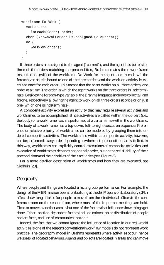
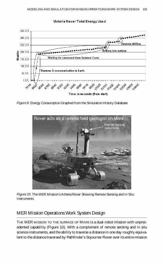