modeling and simulation of thermoelectric device used as a heat pump and an electric generator under...
TRANSCRIPT
Seediscussions,stats,andauthorprofilesforthispublicationat:http://www.researchgate.net/publication/280029098
ModelingandsimulationofthermoelectricdeviceworkingasaheatpumpandanelectricgeneratorunderMediterraneanclimate
ARTICLEinENERGY·JULY2015
ImpactFactor:4.16·DOI:10.1016/j.energy.2015.06.090
4AUTHORS,INCLUDING:
BourhanMohammadTashtoush
JordanUniversityofScienceandTechnology
33PUBLICATIONS276CITATIONS
SEEPROFILE
Availablefrom:BourhanMohammadTashtoush
Retrievedon:21July2015
lable at ScienceDirect
Energy xxx (2015) 1e12
Contents lists avai
Energy
journal homepage: www.elsevier .com/locate/energy
Modeling and simulation of thermoelectric device working as a heatpump and an electric generator under Mediterranean climate
Moh'd A. Al-Nimr, Bourhan M. Tashtoush*, Ahmad A. JaradatMechanical Engineering Department, Jordan University of Science and Technology, Irbid, Jordan
a r t i c l e i n f o
Article history:Received 16 February 2015Received in revised form14 June 2015Accepted 22 June 2015Available online xxx
Keywords:Thermoelectric heat pumpThermoelectric generatorDual usageEvacuated tubeSolar energyEnergy saving
* Corresponding author. Tel.: þ962 2 720 1000.E-mail address: [email protected] (B.M. Tashtou
http://dx.doi.org/10.1016/j.energy.2015.06.0900360-5442/© 2015 Elsevier Ltd. All rights reserved.
Please cite this article in press as: Al-Nimr Mgenerator under Mediterranean climate, En
a b s t r a c t
This paper presents a study of a small thermoelectric device used primarily as a heat pump andsecondarily as an electricity generator when space heating and cooling are not required and incidentsolar radiation is sufficient. As a power generator, the thermoelectric device is integrated with anevacuated solar collector to utilize solar power. Performance of the thermoelectric device as a heat pumpand as an electric generator is simulated using MATLAB/SIMULINK. The purpose of this study is to es-timate the energy savings from using the thermoelectric device in its electricity generation mode. Thepotential of energy saving because of this electricity generation mode function, has been examined inthree different cases. These cases represent the operation of the dual mode thermoelectric system intypical home, school and office buildings in the Mediterranean region. In addition, the effects of differentparameters, such as the solar radiation and ambient conditions, on the device performance wereinvestigated for both modes as well as parameters related to the device itself. Furthermore, hours ofoperation were estimated and the economic feasibility of the device was evaluated. Results of this studyinclude performance curves of the thermoelectric device in both modes as well as the estimation of thepayback period for Mediterranean regions.
© 2015 Elsevier Ltd. All rights reserved.
1. Introduction
TEGs (thermoelectric generators) are thermoelectric devices,which generate electric power from any temperature gradientalong its junctions. Thermoelectric devices can also operate to formtemperature gradients if an electric current is applied. This gradientcan be utilized for heating and cooling by controlling the directionof the current and the positions of the poles.
Thermoelectric devices have various advantages in compare toother devices used for similar applications [1], namely: (1) Ther-moelectric generators utilize low-grade thermal energy, which ischeap and available. (2) Thermoelectric generators are environ-mentally friendly, since they do not emit pollutants during opera-tion. (3) Thermoelectric devices have a longer lifetime; becausethere are no moving parts in compare to conventional thermalsystems, such as conventional heat pumps.
In addition to all advantages previously mentioned, thermo-electric heat pumps have a lighter weight, do not contain any fluids,
sh).
A, et al., Modeling and simulaergy (2015), http://dx.doi.org
and their purposes can be changed easily. Therefore, the reliabilityof thermoelectric devices are relatively higher [2]. Also, thermo-electric devices have the advantage over PV (photovoltaic) moduleswhich need direct solar radiation to operate rather than availabletemperature gradients. On the other hand, low efficiency is a majordisadvantage. The efficiency of thermoelectric generators usuallydoes not exceed 10%. However, rapid advancements in semi-conductors technologies show great chances to help overcome thisdisadvantage.
Thermoelectric devices are based on two principles. The firstone is Peltier Effect, which converts electrical energy to thermalenergy. This implies that a direct current drives heat to flowthrough two different junctions. The second principle is SeebeckEffect, which produces an electric potential when a temperaturegradient across two junctions exists [3].
Using thermoelectric devices as power generators, heaters, orcoolers has been studied by many researchers. The followingliterature review has been included to present their findings. Ac-cording to this review, researchers investigated thermoelectricdevices as power generators or as heat pumps alone; however, tothe best of authors' knowledge, they did not study the utilization ofthermoelectric devices for both modes.
tion of thermoelectric device working as a heat pump and an electric/10.1016/j.energy.2015.06.090
Nomenclature
TH hot side temperature of thermoelectric device, KTL cold side temperature of thermoelectric device, KA cross sectional area of thermoelectric module, cmL length of thermoelectric module, cmQC cooling capacity of thermoelectric heat pump, WN number of modules, Na Seebeck factor for thermoelectric element, V/KaT total Seebeck factor for the module, V/KI electrical current, AR electrical resistance of thermoelectric module, UPINH input electrical power for heating, WPINC input electrical power for cooling, Wn number of thermoelectric elements, nTa ambient temperature, KQh heating capacity for thermoelectric heat pump, WCOPH coefficient of performance for heating, COPHK thermal conductance of thermoelectric module, W/KPout output power from thermoelectric generator, WQH absorbed heat at hot side of thermoelectric generator,
W
V voltage difference between hot and cold sides ofthermoelectric device, V
PELEC output electrical power from thermoelectric generator,W
QL absorbed heat at cold side of thermoelectric generator,W
RL load resistance of thermoelectric generator, Uh thermoelectric generator efficiency, %Ai surface area of internal tube, m2
Re Reynolds number, ReV air velocity, m/sr air density, kg/m3
m dynamic viscosity of the air, N s/m2
hia convection heat transfer coefficient, W/(m2 K)Nu Nusselt number, Nuk thermal conductivity of the air, W/(m K)Qth absorbed heat by thermoelectric generator, WAabs absorption area of solar collector, m2
G solar radiation, W/m2
hthermal thermal efficiency of evacuated tube solar collector
M.A. Al-Nimr et al. / Energy xxx (2015) 1e122
Researchers studied experimental and numerical models ofthermoelectric devices used for air heating and cooling. Better COP(coefficients of performance) were recorded by Cosnier et al. [4],Astrain et al. [5], and Riffat et al. [6].
Russel et al. tested the characteristics of a TEC (thermoelectriccooling device) under different ambient conditions. Effects ofdifferent parameters on the performance of the (TEC) device werestudied, those parameters included: the number of the thermo-electric cooling elements, geometric factors, and the resistance ofthe cold and hot junctions. Their results showed that the systemcould run at the minimum power with minimum operating con-ditions [7]. Yilbas and Sahin [8], investigated the integration of arefrigerator with thermoelectric generator. The results exhibitedthat the position of the thermoelectric generator in the middle ofthe evaporator and condenser reduced the overall coefficient ofperformance for the system, and the position in the middle of theambient and the condenser improved the overall coefficient ofperformance of the system. Miranda et al. [9] modeled a thermo-electric cooling device used for air conditioning. The results showedthe increase of the convection heat transfer coefficient by 10%. Heet al. [10] investigated thermoelectric heat pump considered inheating and cooling modes. Photovoltaic/thermal system used toprovide electrical power to the thermoelectric heat pump andthermal power used for domestic water heating. The investiga-tional results revealed that the coefficient of performance of thethermoelectric heat pump was greater than 0.45 and the watertemperature of the storage tank was approximately 9 �C. Shen et al.[11] modeled and examined an innovative thermoelectric heatpump. The results have shown that the coefficient of performanceof the thermoelectric heat pump was close to that in traditional airconditioner and radiant air conditioner, but its cost is higher. Zhaoet al. [12] investigated the integration of both phase change ma-terial as heat storing system and thermoelectric cooler. The resultsexhibited that the coefficient of performance was in the range of0.87e1.22 and the phase change material reduced the electricityconsumption by 35.3%.
Zhang et al. [13], Zheng et al. [14], and He et al. [15] designedthermoelectric systems in which solar collectors were integrated fordouble functions: the first was Electricity Generation and the second
Please cite this article in press as: Al-Nimr MA, et al., Modeling and simulagenerator under Mediterranean climate, Energy (2015), http://dx.doi.org
was Water Heating. Their results showed that integrating thermo-electric devices with solar collectors was economically feasible, andsuch integration could be used for large-scale applications. Thesestudies also revealed the relationships between the electrical andthermal efficiencies with solar radiation, number of thermoelectricelements, water temperature, and ambient temperature.
Kinsella et al. [16] studied a thermoelectric device to generateelectricity used to charge a battery. Krishna et al. [17] simulated athermoelectric generator and a photovoltaic module using MAT-LAB. Their systemwas designed to harvest thermal energy rejectedfrom car engines and reuse it for air heating, air-cooling, lighting,and charging the battery.
Montecucco and Knox [3], Rezania et al. [18], and Kraemer et al.[19] modeled and simulated a thermoelectric device to produceelectricity with maximum power output. Both electrical and ther-mal models were simulated. Their results showed that the simu-lation results were close to experimental records for the (TEGs).They also showed that the maximum power generation could beachieved at various thermal and electrical resistance values.
Lesage et al. [20], Nia et al. [21], and Date et al. [22] designedthermoelectric generators, which utilized solar energy as a sourcefor electricity generation. Their results showed the relationshipbetween the optimum load and the maximum output power. Theyalso showed that the thermoelectric generator was a promisingtechnology for power generation from renewable energy sourcesrather than fossil fuels.
Martinez et al. [23] presented a thermoelectric generator, whichcould be cooled by itself without the need for extra electrical po-wer. Their results showed that thermoelectric self-cooling systemscould work as temperature controllers.
Francis et al. [24] simulated a refrigeration thermoelectric de-vice at different working conditions using MATLAB. Their resultsshowed that the COP was affected by the temperature differencebetween the heat sink and the heat source; hence, the COP wasmaximized when the temperature difference was minimized.
Maneewan et al. [25] simulated the combination of a thermo-electric generator with a solar collector installed on a rooftop inorder to reduce an attic heat gain. The proposed system generatedenough electricity to run a fan used to cool the system and
tion of thermoelectric device working as a heat pump and an electric/10.1016/j.energy.2015.06.090

Fig. 1. Schematic drawing of the system. (A) Evacuated Tube Solar Collector. (B) ACSource. (C) DC Source. (D) Thermoelectric Device. (E) Battery. (F) Space to beconditioned.
M.A. Al-Nimr et al. / Energy xxx (2015) 1e12 3
minimize the ceiling heat addition. The results showed that thesaved electricity per year was 362-kWh and the payback period ofthe system was 4.36-years.
Singh et al. [26] designed a thermoelectric generator combinedwith thermos-syphon to produce electric power. The temperaturedifference between the hot and the cold junctions was in the rangeof (40e60)-�C. The results showed that the system could generateelectric power from low temperature difference, especially when itwas used in rural areas.
Tayebia et al. [27] studied and optimized a micro fabricatedthermoelectric generator made from thin film. The results revealedthat this kind of fabrication could give an efficiency competitivewith the traditional one and a fewer intermittent as an energysource. Hadjistassou et al. [28] proposed a model to develop theoptimal efficiency of thermoelectric generator. The model was validfor temperature range from 298 K to 623 K. The Results exhibitedthat the suggested model had the maximum efficiency of 5.29% at atemperature difference of 324.6 K. Yusop et al. [29] studied a modelof hybrid thermoelectric generator with solar energy. The shapingmethod dependent on the exponential function of reverse dynamicstudy was used in order to stabilize the electrical voltage. The re-sults exhibited that the suggested method would be applied inorder to track the thermoelectric module performance. Attia et al.[30] designed the low temperature difference of thermoelectricgenerator used for small power generation. The investigationalresults showed that the typical thermoelectric generator couldproduce the highest power. Fisac et al. [31] studied the integrationof thermoelectric modules with photovoltaic modules in order tocool the back side of the photovoltaic modules and increase theirefficiency. In the mean while, the temperature absorbed by ther-moelectric device was used to produce electricity. As a result, thetotal electrical energy production from the system was increased.Raghavendran and Asokan [32] simulated an analytical model ofthermoelectric generator with battery that assisted the medicinalserver. The suggested model used the maximum power pointtracker in order to get the peak power from the system. The resultsshowed that the efficiency of the thermoelectric generator wasimproved with the tracking system.
This paper presents modeling and simulation of a thermoelec-tric device used as a power generator (TEG) and as a heat pump forcooling and heating. The thermoelectric system will be functionalas a power generator when air conditioning is not needed. Usingthermoelectric devices for those two purposes under Mediterra-nean climate is very advantageous. This system is used to generateelectricity when there are moderate weather conditions like thosein spring and autumn. In this time of year there is no need for airconditioning since the temperature is near the thermal comfortlevel. In addition, it can operate as a power generator when thespace is unoccupied by residents like in vacations or off days andafter working hours.
2. System overview
2.1. Components and mechanism
Referring to Fig. 1, the system consists of an evacuated tube solarcollector (A), which receives solar radiation and converts it intothermal energy transferred to the thermoelectric generator (D) togenerate power during its power generation mode. Then, thisgenerated power is transferred to the battery (E) to be stored.During the heat-pumping mode, electric power is provided by anAC source (B), then it is converted into DC and supplied to thethermoelectric device (D) by a DC source (C). The thermoelectricdevice (D) converts electric energy into thermal energy, which isused to change the air temperature of the space (F) using a fan. This
Please cite this article in press as: Al-Nimr MA, et al., Modeling and simulagenerator under Mediterranean climate, Energy (2015), http://dx.doi.org
fan is also used to circulate air around the cold junction in order toextract rejected heat in the power generation mode.
In addition to the mentioned components, there are two morecomponents: the first one is the MPPT (maximum power pointtracker), which is a type of a control system that works on calcu-lating the output current and voltage from the TEG (thermoelectricgenerator). This will change the duty cycle of the converter tomaintain the output power to its maximum. The second compo-nent is the fan controller, which calculates the speed and the cur-rent of the fan to control the speed.
The studied system contains 18 thermoelectric modules and 18evacuated tubes.
2.2. The heat pump
When the ambient temperature is low and falls in the range of(0e19)-�C, the thermoelectric system will be functioning as a heatpump. Under these conditions, the system is used for space heating,and electric power is drawn from the DC source to create a tem-perature gradient across the junctions. Heat is then transferred intothe space e which acts as a heat sink-using the fan.
The system will also be functioning as a heat pump when theambient temperature is high and falls in the range of (26e35)-�C.Under these conditions, the system is used for space cooling; thiscan happen by reversing the direction of the direct current. Thisimplies that the thermoelectric device will start cooling the airinstead of heating it.
2.3. Electricity generator
The thermoelectric system will be functioning as a powergenerator when the ambient temperature is moderate and spaceheating or cooling is not necessary. Under these conditions, thesolar thermal collector absorbs solar radiation to heat water. Thiswater will be circulating to act as a heat source for the (TEG), and itwill be stored in a tank to be used in other domestic applications.The cold junction's temperature can be controlled by exposing it to
tion of thermoelectric device working as a heat pump and an electric/10.1016/j.energy.2015.06.090
M.A. Al-Nimr et al. / Energy xxx (2015) 1e124
outdoor ambient temperature, or by utilizing any other coldreservoir like geothermal cold-water sources such as water wells.
3. Modeling and simulation
3.1. Heat pump model
A simplemodel is proposed for the thermoelectric device, whichis valid for all geometries. The heat balance equations are appliedon both the hot and cold sides.
3.1.1. Assumptions
� The thermal conductivity (k), electrical conductivity (s), and theSeebeck factor (a) are constants and temperature independent.They are found at the average temperature between the hot andcold junctions.
� The model is valid for one or many pairs of legs and severalmodules of thermoelectric devices according to reference [7].
� The value of the hot side temperature is higher than the ambienttemperature, and the cold side temperature is below theambient temperature according to reference [6].
3.1.2. Governing equationsThe system as a cooler is described by the following set of
equations:
TH ¼ Ta þ 13 (1)
K ¼ kAL
(2)
aT ¼ na (3)
TH ¼ LAs
(4)
QC ¼ N�aT ITL � KðTH � TLÞ � 0:5RI2
�(5)
PINC ¼ N�aT IðTH � TLÞ þ RI2
�(6)
COPC ¼ QC
PINC(7)
The above equations are valid for one module with one or manypairs of legs and several thermoelectric modules. Equation (2) isbased on the assumption that the hot side temperature is higherthan the ambient temperature.
The heat balance at the hot or the cold junctions refers to threemain heat sources: (A) Joule Heat. (B) Conduction Heat. (C) PeltierHeat Pumping. The Joule Heat means that the current flows toproduce a resistance along the thermoelectric module. The Con-duction Heat occurs when heat is transferred from the hot junctionto the cold junction across the module. The Peltier effect HeatPumping is when heat is absorbed by one junction and releasedfrom the other junction.
The performance of the thermoelectric system as a heat pump isdescribed by the COP (coefficient of performance). The COP isdefined as the fraction of useful thermal heat, which is absorbed orreleased to the provided electric work.
To describe the system as a heater, the following set of equationsare used in addition to equations (2)e(4) [34]:
Please cite this article in press as: Al-Nimr MA, et al., Modeling and simulagenerator under Mediterranean climate, Energy (2015), http://dx.doi.org
TH ¼ Ta � 3 (8)
QH ¼ N�aT ITH � KðTH � TLÞ þ 0:5RI2
�(9)
PINC ¼ N�aT IðTH � TLÞ þ RI2
�(10)
COPH ¼ QH
PINC(11)
Equation (8) is based on the assumption that the cold sidetemperature is below the ambient temperature.
3.2. Thermoelectric generator model
3.2.1. Assumptions
� The system is runningundermoderateweather conditions (Springand Autumn), or when there are no occupants in the space.
� The thermal conductivity (k), electrical conductivity (s), and theSeebeck factor (a) are constants and temperature independent.They are found at the average temperature between the hot andcold junctions.
3.2.2. Governing equations
QH ¼ N�aT ITH þ KðTH � TLÞ � 0:5RI2
�(12)
QC ¼ N�aT ITL þ KðTH � TLÞ þ 0:5RI2
�(13)
Pout ¼ QH � QL (14)
I ¼ nfðTH � TLÞRþ RL
(15)
V ¼ NðnfðTH � TLÞ � IRÞ (16)
Pelectric ¼NðnfðTH � TLÞÞ2
4R(17)
h ¼ PoutQH
(18)
3.3. Evacuated tube solar collector model
A simple thermal analysis is used to describe the output of theevacuated tube solar collector. The purpose of using the model is topredict the temperatures of the hot and the cold sides of thethermoelectric generator. The model is similar to the one found inreference [33].
Re ¼ rVDi
m(19)
Nu ¼ 0:3Re0:6 (20)
hia ¼ NukDi
(21)
tion of thermoelectric device working as a heat pump and an electric/10.1016/j.energy.2015.06.090

Fig. 3. Building block diagram of the thermoelectric air cooler heat pump, (Cooling Mode) in MATLAB/SIMULINK.
Fig. 2. Building block diagram of the thermoelectric air heater heat pump, (Heating Mode) in MATLAB/SIMULINK.
M.A. Al-Nimr et al. / Energy xxx (2015) 1e12 5
Please cite this article in press as: Al-Nimr MA, et al., Modeling and simulation of thermoelectric device working as a heat pump and an electricgenerator under Mediterranean climate, Energy (2015), http://dx.doi.org/10.1016/j.energy.2015.06.090

M.A. Al-Nimr et al. / Energy xxx (2015) 1e126
Rth ¼ 1h A
(22)
ia iQth ¼ GAabshthN
(23)
TL ¼ Taþ GAabshthN
Rth (24)
TH ¼ Taþ GAabshthN
ðRth þ RÞ (25)
3.4. Simulation
3.4.1. Heat pumpFig. 2 presents a building block diagram of the thermoelectric
heat pump in heating mode. This diagram is simulated usingMATLAB/SIMULINK environment.
Fig. 4. Flow chart for the heat p
Please cite this article in press as: Al-Nimr MA, et al., Modeling and simulagenerator under Mediterranean climate, Energy (2015), http://dx.doi.org
The inputs for the heating mode simulation are the hotside temperature, the ambient temperature, and the elec-tric current. The outputs of the simulation are the cold sidetemperature, the heating capacity, and the coefficient ofperformance.
Fig. 3 shows a complete building block diagram of the ther-moelectric heat pump (cooling mode). This diagram is simulatedusing MATLAB/SIMULINK environment.
Inputs for the cooling mode are the ambient temperature, thecold side temperature, and the electric current. The outputs of thesimulation are the hot side temperature, the cooling capacity, andthe coefficient of performance.
Fig. 4 shows a flow chart designed for the system simulation as aheat pump (Cooling and Heating modes). Programming of thesimulation is based on this flow chart.
3.4.2. Thermoelectric generatorFig. 5 shows a complete building block diagram of the ther-
moelectric generator. This diagram is simulated using MATLAB/SIMULINK environment.
ump simulation algorithm.
tion of thermoelectric device working as a heat pump and an electric/10.1016/j.energy.2015.06.090

Fig. 5. Building block diagram for the thermoelectric generator (TEG) in MATLAB/SIMULINK.
M.A. Al-Nimr et al. / Energy xxx (2015) 1e12 7
The inputs for the power generation mode are the weatherconditions for Irbid city in Jordan. The outputs of the simulation arethe useful heat absorbed by the thermoelectric device, the tem-peratures of the hot and the cold sides, the voltage difference, theelectric current, the power, and the efficiency.
Fig. 6 shows a flow chart designed for the system simulation as apower generator. Programming of the simulation is based on thisflow chart.
3.5. Selected parameters
3.5.1. Thermoelectric moduleThe physical specifications of the selected thermoelectric
module are shown in Table 1, whereas the electrical and thermalspecifications of the thermoelectric module are shown in Table 2.
3.5.2. Evacuated tube solar collectorTable 3 shows the geometrical specifications of the evacuated
tube solar collector selected for this study.
4. Results and discussion
4.1. Heat pump
4.1.1. Heating modeFig. 7 shows the electrical current variation with the electrical
input power. It is noticed that as the electrical current increases theinput power increases and reaches its peak value of 2208 W at themaximum current value of 10 A. In addition, it is noticed that thecoefficient of performance reaches its maximum value of 3.8 whenthe electrical current is low. The coefficient of performance
Please cite this article in press as: Al-Nimr MA, et al., Modeling and simulagenerator under Mediterranean climate, Energy (2015), http://dx.doi.org
decreases and reaches its minimum value of 1.26 when the electriccurrent increases and reaches its maximum value of 10 A.
Fig. 8 shows the relationship between the electric power inputwith the heating capacity and the coefficient of performance forheating mode. It is noticed that when the input power is low, thecoefficient of performance reaches its maximum value. The coeffi-cient of performance decreases to its minimum value as the elec-trical power increases to its peak point. Furthermore, it can benoticed that when the electrical input power to the heat pumpincreases, the heating capacity also increases. Accordingly, thethermoelectric heat pump can operate at the maximum coefficientof performance with low input power, but the heating capacity islow and will not be sufficient for the intended purpose.
Fig. 9 shows the relationship between the heating capacity andinput power of the thermoelectric heat pump with the hot sidejunction temperature. It is concluded that the hot side temperatureincreases when the heating capacity and input electrical powerincrease.
4.1.2. Cooling modeFig. 10 shows the coefficient of performance as a function of the
input power and the cooling capacity. It is noticed that the coeffi-cient of performance reaches its maximum value of 2.35 when thepower input is low. The coefficient of performance decreases to itsminimum value at the input power's peak value, and the coolingcapacity increases to its maximum value.
Fig. 11 shows the relationship between the electric current withcoefficient of performance and cooling capacity. When the elec-trical current is low, the coefficient of performance is high. Thecoefficient of performance decreases to its minimum value of 0.38when the electric current is in its maximum value of 8.5 A. Thecooling capacity also increases to its peak value of 626 W.
tion of thermoelectric device working as a heat pump and an electric/10.1016/j.energy.2015.06.090

Fig. 6. Flow chart for the power generator simulation algorithm.
Table 1Physical specifications of the thermoelectric module that have been chosen for thisstudy, [35].
Physical properties Value Unit
Length 6.27 cmWidth 6.27 cmArea 39.31 cm2
Number of thermocouples 97 N
Table 2Electrical and thermal specifications of the thermoelectric module, which has beenchosen for this study, [35].
Property Value Unit
Power 9 WLoad voltage 3.28 VInternal resistance 1.15 UCurrent 2.9 AOpen circuit voltage 6.5 VEfficiency at 200 �C temperature difference 4.5 %Thermal conductivity 0.018 W/(cm K)Heat flux 5.52 W/cm2
M.A. Al-Nimr et al. / Energy xxx (2015) 1e128
Please cite this article in press as: Al-Nimr MA, et al., Modeling and simulation of thermoelectric device working as a heat pump and an electricgenerator under Mediterranean climate, Energy (2015), http://dx.doi.org/10.1016/j.energy.2015.06.090

Table 3Geometrical specifications of the evacuated tube solar collector, which was selectedfor this study, [13].
Geometrical properties Value Unit
Outer glass tube diameter 0.07 MInner tube diameter 0.058 MLength of the tube 1.95 MNumber of tubes 18 NNumber of solar collectors 1 N
Fig. 7. The relationship between the coefficient of performance and the input powerwith the electric current.
Fig. 8. The relationship between the coefficient of performance and the heating ca-pacity with the input power.
Fig. 9. The relationship between the heating capacity and the input power with thehot side temperature.
Fig. 10. The relationship between the coefficient of performance and the cooling ca-pacity with the input power.
Fig. 11. The relationship between the coefficient of performance and the cooling ca-pacity with the electric current.
M.A. Al-Nimr et al. / Energy xxx (2015) 1e12 9
Please cite this article in press as: Al-Nimr MA, et al., Modeling and simulagenerator under Mediterranean climate, Energy (2015), http://dx.doi.org
Fig. 12 shows the relationships between the cold side junctiontemperature with input electrical power and cooling capacity. It isnoticed that the needed input power increases when the cold sidetemperature increases. This is explained by the increase in thecooling capacity needed to cool the ambient at relatively hightemperature of the cold side.
4.2. Power generator
Fig. 13 shows the relationship between the cold and hot junc-tions temperatures and the absorbed heat. It is noticed that the hotside temperature increases to its maximum value of 433.8 K whenthe absorbed heat reaches its peak value of 845.9W in addition, thecold side temperature increases by conduction to its maximumvalue of 359.8 K.
Fig. 12. The relationship between the input power and the cooling capacity with thecold side temperature.
tion of thermoelectric device working as a heat pump and an electric/10.1016/j.energy.2015.06.090

Fig. 14. The relationship between the electric current and the temperature differentwith the electric power output.
Fig. 15. The relationship between the absorbed heat and the electric power outputwith the thermoelectric generator efficiency.
Fig. 13. The relationship between the hot side temperature and the cold side tem-perature with the absorbed heat.
M.A. Al-Nimr et al. / Energy xxx (2015) 1e1210
The difference in temperature is an important factor since itplays a significant role in generating the output power from thethermoelectric generator. When the difference in temperature in-creases, the electrical current and the power generation increase totheir maximum points of 1.027 A and 21.85 W; respectively at the
Table 4Different operating conditions for the heat pump and the thermoelectric generator in su
The percentage of operation hours for the heat pump (Cooling Mode) 10%Energy consumption from the heat pump (kWh) 3.084The percentage of day light operation hours (%) 0Energy production by thermoelectric generator (kWh) 0The percentage of thermoelectric generator energy production from heat
pump energy consumption (%)0
Please cite this article in press as: Al-Nimr MA, et al., Modeling and simulagenerator under Mediterranean climate, Energy (2015), http://dx.doi.org
maximum temperature difference value of 74 �C, as shown inFig. 14.
Fig. 15 describes the relationship between the generated electricpower and the total heat absorbed by the thermoelectric generator,with the efficiency of thermoelectric generator. It can be seen thatthe heat absorbed by the thermoelectric generator increases to ahigh temperature of the hot side junction, leading to an increase inthe output power and generator efficiency; respectively. Themaximum thermoelectric generator efficiency is 2.58%.
4.3. Energy calculations
Tables 4 and 5 show the energy calculations results for thesystem as a heat pump and as a generator under Summer andWinter conditions; respectively.
It can be seen that the thermoelectric generator contributes inlow percentage of the energy consumption reduction from the heatpump. This percentage is acceptable since using the device forelectricity generation is a secondary purpose. In addition, thethermoelectric generator can be fully operated when there is noneed for the heat pump in Autumn and Spring seasons.
As can be seen from these Tables 6e8, the thermoelectricgenerator saves 19% of energy consumption from the heat pump inboth heating and cooling mode throughout the year in the typicalschool building. Furthermore, the thermoelectric generator saves8% of energy consumption from the heat pump in both heating andcooling modes throughout the year in the typical office building.The thermoelectric generator saves 6% of energy consumption fromthe heat pump in both heating and cooling mode throughout theyear in the typical home building.
4.4. Summary of the results
The results of the thermoelectric heat pump (cooling mode)simulation are shown in Figs. 10e12. The calculated coefficient ofperformance for cooling was 0.48 for a current of 7.5 A. Input powerwas 1285 W and the cooling capacity was 618.94 W. Similarly, theresults of thermoelectric heat pump (heating mode) are shownin Figs. 7e9. The calculated coefficient of performance for heatingwas 1.46 for a current of 7.5 A. Input power was 1268 W and theheating capacity was 1860.4 W.
The results of the thermoelectric generator were obtained andrevealed that the saved energy was 9.9% of the energy consumptionfrom the thermoelectric heat pump (cooling mode), 7.7% of theenergy consumption from the thermoelectric heat pump (heatingmode), and 4.3% of the total energy consumption of the heat pumpfor one year.
5. Economic analysis
An economic study is carried out and presented in this paper.The lifetime of the thermoelectric device is known to be 20-years.The device includes 18 thermoelectric modules which are con-nected electrically in series and thermally in parallel. The total areaof the system is 0.0708m2. The initial investment includes the costs
mmer.
20% 30% 40% 50%6.168 9.252 12.336 15.420
10 10, 20 10, 20, 30 10, 20, 30, 40, 500.025 0.025, 0.05 0.025, 0.05, 0.075 0.025, 0.050 0.075, 0.100 0.1254 3, 5.4 2, 4, 6 1.6, 3.2, 4.9, 6.4, 8.1
tion of thermoelectric device working as a heat pump and an electric/10.1016/j.energy.2015.06.090

Table 7Comparison of energy consumption from thermoelectric heat pump and energy production by thermoelectric generator in an office building in Jordan (Case Study).
Months of the year 1 2 3 4 5 6 7 8 9 10 11 12 Total
Days of the work 24 24 24 24 24 24 24 24 24 24 24 24 264Operation hours 8 8 0 0 0 8 0 8 0 0 0 8 40Energy consumption (kWh) 185 213 0 0 0 577 0 137 0 0 0 275 868Holydays, spring and autumn days 6 6 30 30 30 12 30 6 30 30 30 6 246After work hours 48 48 0 0 0 48 0 48 0 0 0 48 159Energy production (kWh) 2 2 6 7 9 6 12 2.8 7 6 5 2 72Energy saving (%) 1 1 e e e 11 e 2 e e e 1 8
Table 8Comparison of energy consumption from thermoelectric heat pump and energy production by thermoelectric generator in a typical home building in Jordan (Case Study).
Months of the year 1 2 3 4 5 6 7 8 9 10 11 12 Total
Days of the work 30 30 30 30 30 30 30 30 30 30 30 30 365Operation hours for heat pump (H & C) M 8 8 0 0 0 8 8 8 0 0 0 8 40Energy consumption from the heat pump (kWh) 231 266 171 231 171 0 0 0 344 125Holydays, spring and autumn days 30 30 30 30 30 30 30 30 30 30 30 30 30During work hours 5 6 0 0 0 6 6 6 0 0 0 5 34Energy production by generator (kWh) 4. 5 6 7 9 5 6 4 7 6 5 4 74Energy saving by thermoelectric generator (%) 2 2 e e e 8 4 3 e e e 1 6
Table 6Comparison of energy consumption from thermoelectric heat pump and energy production by thermoelectric generator in a typical school in Jordan (Case Study).
Months of the year 1 2 3 4 5 6 7 8 9 10 11 12 Total
Days of the work 5 15 23 22 22 18 0 11 22 17 21 25 201Operation hours 6 6 0 0 0 6 0 6 0 0 0 6 30Energy cons. (kWh) 28.9 99.9 0 0 0 32.5 0 47.1 0 0 0 215 423.7Holydays, spring and autumn days 25 15 30 30 30 12 30 19 30 30 30 5 286After work hours 10 45 0 0 0 10 0 44 0 0 0 50 159Energy prod.(kWh) 4.20 3.99 6.5 7.7 9.5 6.95 12. 6.38 7.5 6.6 5.7 2.1 80.02Energy saving (%) 15 4 e e e 21 e 14 e e e 1 19
Table 5Different operating conditions for the heat pump and the thermoelectric generator in winter.
The percentage of operation hours for the heat pump (Heating Mode) 10% 20% 30% 40% 50%Energy consumption from the heat pump (kWh) 3.04 6.086 9.130 12.173 15.216The percentage of day light operation hours of the
thermoelectric generator (%)0 0.0175 0.0175, 0.0341 0.0175, 0.0341, 0.052 0.0175, 0.0341, 0.052,
0.0691, 0.087Energy production from thermoelectric generator (kWh) 0 0.0175 0.0175, 0.0341 0.0175, 0.0341, 0.052 0.0175, 0.0341, 0.052
0.0691, 0.087The percentage of thermoelectric generator energy production
from heat pump energy consumption (%)0 2.9 1.9, 3.8 1.4, 2.9, 4.3 1.2, 2.3, 3.5, 4.6, 5.8
M.A. Al-Nimr et al. / Energy xxx (2015) 1e12 11
of the thermoelectric device with the fan, the maximum pointpower tracker and the battery. Maintenance costs are assumed tobe neglected.
The annual energy production was 42 kWh for the maximumtemperature difference between the both sides of 74 �C. The annualenergy production became 70 kWh when the maximum temper-ature difference between the two sides became 94 �C. The gener-ated energy from this device is used to charge a small battery,which can be used for household applications.
Table 9Capital cost of thermoelectric device components, [36].
Item No. of units One unitprice (JOD)
Totalprice (JOD)
Thermoelectric modules 18 6 108Small cooling fan 1 4 4Electric battery 1 4 4Fan controller 1 2 2Maximum power point tracker 1 20 20Sum e e 138
6. Closing summary
Modeling of a small thermoelectric system integrated with anevacuated tube solar collector used for heating, cooling and elec-tricity generation is studied and simulated usingMATLAB. This studyincludes mathematical modeling of the system's behavior, simula-tion procedures, energy calculations, and an economic analysis.
Performance curves describing the system operating as a heatpump (heating and cooling) and as an electricity generator are
Please cite this article in press as: Al-Nimr MA, et al., Modeling and simulagenerator under Mediterranean climate, Energy (2015), http://dx.doi.org
obtained. The curves show the relationship between manydifferent variables. In addition, different tables are presented toshow results of the energy calculations and the economic study(Tables 9 and 10).
The studied system operates as a heat pump (cooling mode)when the temperature difference between the hot and cold junc-tions is 28 �C. The calculated values of the coefficient of perfor-mance varied in the range of 0.38e2.35.
tion of thermoelectric device working as a heat pump and an electric/10.1016/j.energy.2015.06.090
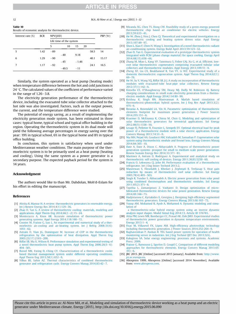
Table 10Results of economic analysis for thermoelectric device.
Interest rate (%) BCR NPV(JOD) PBP (Yr)
Life time of the system
5 10 15 20
5 1.42 �89�40 9.18
58.5 14
6 1.29 �90�45 �1.46
40.1 15.17
7 1.17 �92�49.5 �11
24.1 16.5
M.A. Al-Nimr et al. / Energy xxx (2015) 1e1212
Similarly, the system operated as a heat pump (heating mode)when temperature difference between the hot and cold junctions is24 �C. The calculated values of the coefficient of performance variedin the range of 1.26e3.8.
The electricity generation performance of the thermoelectricdevice, including the evacuated tube solar collector attached to thehot side was also investigated. Factors, such as the output power,the current, and the temperature difference were studied.
The potential of energy saving, as a result of implementing theelectricity generation mode system, has been estimated in threecases: typical home, typical school and typical office building in theregion. Operating the thermoelectric system in its dual mode willyield the following average percentages in energy saving over theyear: 19% in typical school, 6% in the typical home and 8% in typicaloffice building.
In conclusion, this system is satisfactory when used underMediterranean weather conditions. The main purpose of the ther-moelectric system is to be primarily used as a heat pump (heatingand cooling). Using the same system as a power generator is asecondary purpose. The expected payback period for the system is14 years.
Acknowledgment
The authors would like to than Mr. Dahdolan, Moh'd-Eslam forhis effort in editing the manuscript.
References
[1] Ahiska R, Mamur H. A review: thermoelectric generators in renewable energy.Int J Renew Energy Res 2014;4(1):129e36.
[2] Zhao D, Tan G. A review of thermoelectric cooling: materials, modeling andapplications. Appl Therm Eng 2014;66(1e2):15e24.
[3] Montecucco A, Knox AR. Accurate simulation of thermoelectric powergenerating systems. Appl Energy 2014;118:166e72.
[4] Cosnier M, Fraisse G, Luo L. An experimental and numerical study of a ther-moelectric air-cooling and air-heating system. Int J Refrig 2008;31(6):1051e62.
[5] Astrain D, Vian JG, Dominguez M. Increase of COP in the thermoelectricrefrigeration by the optimization of heat dissipation. Appl Therm Eng2003;23(17):2183e200.
[6] Riffat SB, Ma X, Wilson R. Performance simulation and experimental testing ofa novel thermoelectric heat pump system. Appl Therm Eng 2006;26(5e6):494e501.
[7] Russel MK, Ewing D, Ching CY. Characterization of a thermoelectric coolerbased thermal management system under different operating conditions.Appl Therm Eng 2013;50(1):652e9.
[8] Yilbas BS, Sahin AZ. Thermal characteristics of combined thermoelectricgenerator and refrigeration cycle. Energy Convers Manag 2014;83:42e7.
Please cite this article in press as: Al-Nimr MA, et al., Modeling and simulagenerator under Mediterranean climate, Energy (2015), http://dx.doi.org
[9] Miranda �AG, Chen TS, Hong CW. Feasibility study of a green energy poweredthermoelectric chip based air conditioner for electric vehicles. Energy2013;59:633e41.
[10] He W, Zhou J, Hou J, Chen CJ. Theoretical and experimental investigation on athermoelectric cooling and heating system driven solar. Appl Energy2013;107:89e97.
[11] Shen L, Xiao F, Chen H, Wang S. Investigation of a novel thermoelectric radiantair-conditioning system. Energy Build April 2013;59:123e32.
[12] Zhao D, Tan G. Experimental evaluation of a prototype thermoelectric systemintegrated with PCM (phase change material) for space cooling. Energy April2014;68(15):658e66.
[13] Zhang M, Miao L, Kang YP, Tanemura S, Fisher CAJ, Xu G, et al. Efficient, low-cost solar thermoelectric cogenerators comprising evacuated tubular solarcollectors and thermoelectric modules. Appl Energy 2013;109:51e9.
[14] Zheng XF, Liu CX, Boukhanouf R, Yan YY, Li WZ. Experimental study of adomestic thermoelectric cogeneration system. Appl Therm Eng 2014;62(1):69e79.
[15] HeW, Su Y, Wang YQ, Riffat SB, Ji J. A study on incorporation of thermoelectricmodules with evacuated-tube heat-pipe solar collectors. Renew Energy2012;37(1):142e9.
[16] Kinsella CE, O'Shaughnessy SM, Deasy MJ, Duffy M, Robinson AJ. Batterycharging considerations in small scale electricity generation from a thermo-electric module. Appl Energy 2014;114:80e90.
[17] Krishna K, Singh RN, Manivannan A. Matlab based simulation ofthermoelectric-photovoltaic hybrid system. Int J Eng Res Appl 2013;3(2):975e9.
[18] Rezania A, Rosendahl LA, Yin H. Parametric optimization of thermoelectricelements footprint for maximum power generation. J Power Sources2014;255:151e6.
[19] Kraemer D, McEnaney K, Chiesa M, Chen G. Modeling and optimization ofsolar thermoelectric generators for terrestrial applications. Sol Energy2012;86(5):1338e50.
[20] Lesage FJ, Pelletier R, Fournier L, Sempels EV. Optimal electrical load for peakpower of a thermoelectric module with a solar electric application. EnergyConvers Manag 2013;74:51e9.
[21] Nia MH, Nejad AA, Goudarzi AM, Valizadeh M, Samadian P. Cogeneration solarsystem using thermoelectric module and fresnel lens. Energy Convers Manag2014;84:305e10.
[22] Date A, Date A, Dixon C, Akbarzadeh A. Progress of thermoelectric powergeneration systems: prospect for small to medium scale power generation.Renew Sustain Energy Rev 2014;33:371e81.
[23] Martinez A, Astrain D, Rodriguez A. Experimental and analytical study onthermoelectric self cooling of devices. Energy 2011;36(8):5250e60.
[24] Francis O, Lekwuwa CJ, John IH. Performance evaluation of a thermoelectricrefrigerator. Int J Eng Innov Technol 2013;2.
[25] Maneewan S, Hirunlabh J, Khedari J, Zeghmati B, Teekasap S. Heat gainreduction by means of thermoelectric roof solar collector. Sol Energy2005;78(4):495e503.
[26] Singh R, Tundee S, Akbarzadeh A. Electric power generation from solar pondusing combined thermosyphon and thermoelectric modules. Sol Energy2011;85(2):371e8.
[27] Tayebia L, Zamanipourc Z, Vashaeec D. Design optimization of micro-fabricated thermoelectric devices for solar power generation. Renew Energy2014;69:166e73.
[28] Hadjistassou C, Kyriakides E, Georgiou J. Designing high efficiency segmentedthermoelectric generators. Energy Convers Manag 2013;66:165e72.
[29] Yusop AM, Mohamed R, Ayob A, Mohamed A. Dynamic modeling and simu-lation ofa thermoelectric-solar hybrid energy system using an inverse dynamic
analysis input shaper. Model Simul Eng 2014:13. Article ID 376781.[30] Attia PM, Lewis MR, Bomberger CC, Prasad AK, Zide JMO. Experimental studies
of thermoelectric power generation in dynamic temperature environments.Energy 2013:1e4.
[31] Fisac M, Villasevil FX, L�opez AM. High-efficiency photovoltaic technologyincluding thermoelectric generation. J Power Sources 2014;252:264e9.
[32] Raghavendran P, Asokan R. TEG based power system for operation of healthmonitoring server in industries. Int J Eng Technol IJET Dec 2013;5(6).
[33] Kalogirou SA. Solar energy engineering: processes and systems. AcademicPress; 2009.
[34] Fraisse G, Ramousse J, Sgorlon D, Goupil C. Comparison of different modelingapproaches for thermoelectric elements. Energy Convers Manag 2013;65:351e6.
[35] JRC 2015. JRC [Online] [accessed 2015 January]. Available from: http://www.jrc.ec.europa.eu.
[36] Aliexpress 1999, Aliexpress [Online] [accessed 2014 November]. Availablefrom: www.aliexpress.com.
tion of thermoelectric device working as a heat pump and an electric/10.1016/j.energy.2015.06.090