modeling errors influencing active structural methods for ... · control strategy in active...
TRANSCRIPT
Available online at www.sciencedirect.com
2212-8271 © 2014 Published by Elsevier B.V. Open access under CC BY-NC-ND license. Selection and peer-review under responsibility of the International Scientific Committee of the 6th CIRP International Conference on High Performance Cuttingdoi: 10.1016/j.procir.2014.03.037
Procedia CIRP 14 ( 2014 ) 494 – 499
ScienceDirect
6th CIRP International Conference on High Performance Cutting, HPC2014
Modeling Errors influencing Active Structural Methods for Chatter Mitigation in Milling Process
Jérémie Monnina,*, Fredy Kusterb, Konrad Wegenerb aMikron Agie Charmilles, Nidau, Switzerland
bIWF, ETH Zurich, Switzerland
* Corresponding author. Tel.: +41 32 366 14 80; fax: +41 32 366 14 09. E-mail address: [email protected]
Abstract
A concept of active structural method dedicated to the mitigation of regenerative chatter in milling process is presented. Thisconcept proposes an adaptronic high performance motor spindle integrating piezoelectric actuators and accelerometers combined with an optimal control strategy whose objective is to increase the productivity in chatter-free machining conditions. The control strategy, named stabilization, explicitly considers the cutting process in the controller synthesis in order to tailor the dynamics of the spindle according to the encountered machining conditions. As this strategy is based on models of machine tool, workpiece and process, modeling errors play a significant role and might corrupt the stability prediction and influence the performance of such active structural method. A series of machining tests illustrates the problematic and points out the difficulty to accurately and reliably predict the occurrence of chatter in milling process. It also indicates the current limitation of the proposed concept.
© 2014 The Authors. Published by Elsevier B.V. Selection and peer-review under responsibility of the International Scientific Committee of the 6th CIRP International Conference on High Performance Cutting.
Keywords: Milling ; Regenerative chatter ; Active structural method ; Stability chart ; Modeling error
1. Introduction
High performance milling operations are regularly confronted to the occurrence of regenerative chatter vibrations due to the important forces generated by this specific manufacturing process. The method investigated here to prevent this phenomenon to happen attempts to adapt the machine structure dynamics using mechatronic system in order to improve the process stability for some given machining conditions. Such active structural method probably represents one of the most promising ways to deal with chatter, mainly due to its high degree of adaptivity and their great development potential. Several applications of such methods have been proposed.
Ries et al. [1] demonstrate the ability of an active motor milling spindle designed for high speed machining operations to increase the critical axial depth of cut. In the presented construction, the front bearing is actively supported in both radial directions by two orthogonal preloaded piezoelectric
stack actuators. One pair of accelerometers and two pairs of non-contact displacement transducers are used to sense the radial vibrations in the vicinity of the actuators. The controller attempts to increase the structural damping of the spindle shaft support using collocated control strategies to reduce the propensity to chatter.
Another solution is proposed by Dohner et al. [2] wherein the front bearing is actively supported in the radial plane by two orthogonal pairs of electrostrictive stack actuators working in push-pull configuration and guided by hydrostatic bearings. A linear-quadratic-Gaussian control, minimizing the influence of the process disturbance on the tool tip, is implemented and found to provide sufficient trade-off between robustness and performance.
Several works investigated the possibility of integrating the process dynamics into the control design. For instance, Mei et al. [3] synthesize a linear-quadratic optimal controller where the control force takes the time delay induced by the regenerative effect into account.
© 2014 Published by Elsevier B.V. Open access under CC BY-NC-ND license. Selection and peer-review under responsibility of the International Scientific Committee of the 6th CIRP International Conference on High Performance Cutting
495 Jérémie Monnin et al. / Procedia CIRP 14 ( 2014 ) 494 – 499
Shiraishi et al. [4] describe the implementation of an optimal linear-quadratic integral controller using Luenberger state observer for the chatter stabilization and the minimization of the tracking error of the cutter on a bench type lathe.
Chen and Knospe [5] present a robust stabilization design using μ-synthesis with DK-iteration. Using this technique, it is possible to derive a controller guarantying a stable process over a certain range of some varying parameters, such as the depth of cut or the spindle speed. These ranges are thus considered as parametric uncertainties.
The robust stabilization technique presented in [5] is applied by van Dijk and co-workers in [6] to the case of a high speed milling spindle fully supported by active magnetic bearings.
The mechatronic design of the active system proposed by Ries et al. [1] is well suited for an industrial transfer due to its high degree of integration of the actuators and sensors into the spindle structure but the proposed control strategies are limited to collocated controls. As demonstrated by Chen and Knospe, model-based controls taking a machining process model into account present greater potential for chatter mitigation. However, their application to real and representative machining conditions is still missing.
This contribution presents an original concept used to mitigate regenerative chatter in milling operation by the means of an active structural control system integrated into an existing high performance milling motor spindle unit in conjunction with an optimal control strategy which explicitly takes the milling process into account.
The second section describes the proposed concept. The functioning of the control strategy is then presented using a simulation example. Finally, several experimental investigations allow to evaluate the validity of the proposed solution and its limitations regarding to modeling errors.
2. Proposed Concept
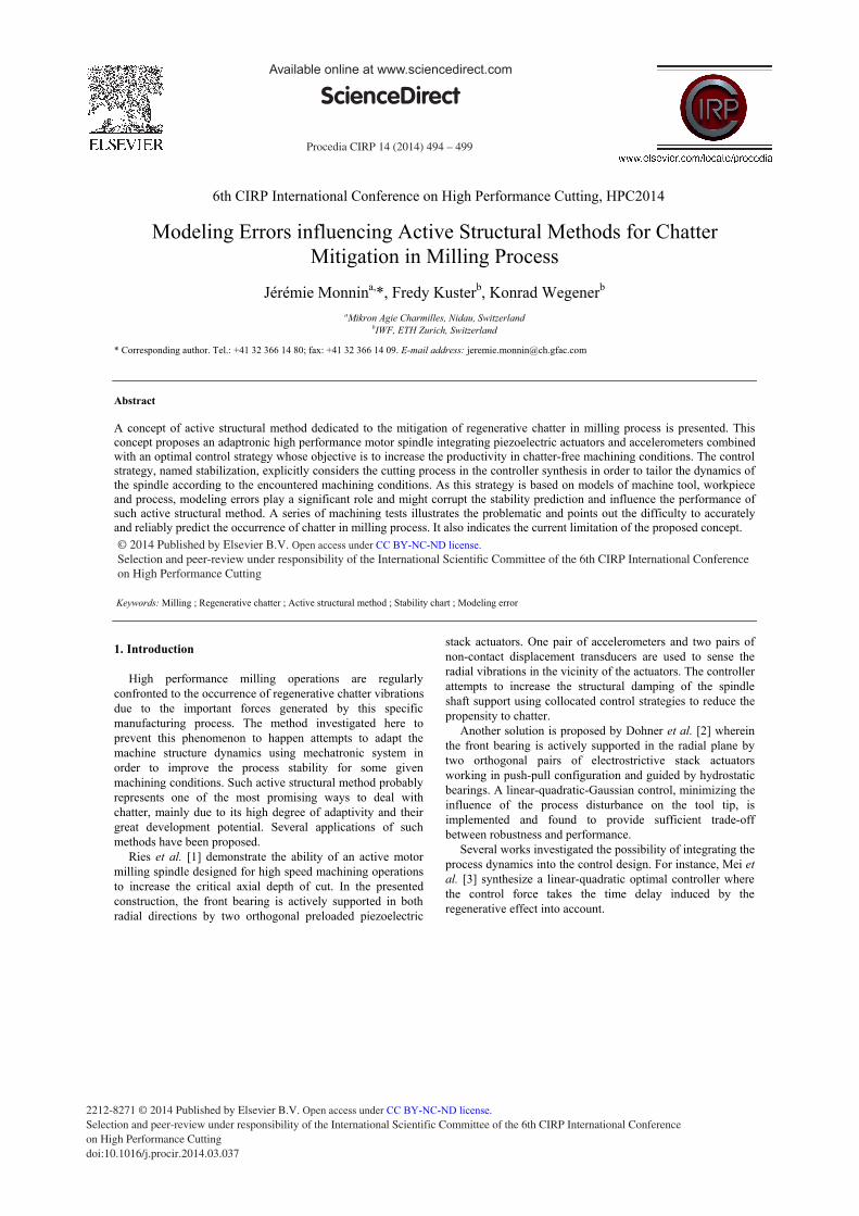
Fig. 1. Flowchart of overall system. C: controller transfer function; G: transfer function of machine structure dynamics; Gkj: transfer function between jth input and kth output of the mechatronic system with j = w, u and k = z, y; P: milling process; R: regenerative effect transfer function; fP: kinematic cutting forces; u: instruction signal delivered to actuating system; w: cutting forces; wR: regenerative cutting forces; y: information provided by sensing system. z: tool center point deviations.
The overall considered system is based on three interconnected subsystems, namely the dynamics of the mechatronic system G, also called plant, the milling process P and the controller C. The interaction of these three subsystems is represented in Fig. 1. The deviations z of the tool center point (TCP) due to the excitation of the cutting forces w influence the effective chip thickness via the regenerative effect R. This makes chatter susceptible to occur. On the other side, some sensors deliver information y on the current state of the machine structure to the controller. Based on this information and a predefined control strategy, the controller provides reference signals u to an actuating system influencing the machine structure dynamics.
In the following subsections, the mechatronic system integrated into the machine tool is described. The proposed control strategy crystallized in the controller is then presented.
2.1. Mechatronic System
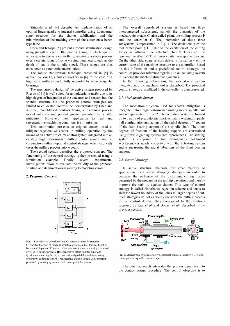
The mechatronic system used for chatter mitigation is integrated into a high performance milling motor spindle unit and is represented in Fig. 2. The actuating system is formed by two pairs of piezoelectric stack actuators working in push-pull configuration and acting on the radial degrees of freedom of the front bearing support of the spindle shaft. The other degrees of freedom of the bearing support are constrained using flexible guiding system (not represented). The sensing system is composed of two orthogonally positioned accelerometers nearly collocated with the actuating system and is measuring the radial vibrations of the front bearing support.
2.2. Control Strategy
In active structural methods, the great majority of applications uses active damping strategies in order to decrease the influence of the disturbing cutting forces generated by the process on the tool tip deviations and thereby improve the stability against chatter. This type of control strategy is called disturbance rejection scheme and tends to shift the lowest boundary of the lobes to larger depths of cut. Such strategies do not explicitly consider the cutting process in the control design. They correspond to the solutions proposed by Ries et al. and Dohner et al., described in the previous section.
Fig. 2. Mechatronic system for active structural control of chatter. TCP: tool center point; n: spindle rotational speed.
The other approach integrates the process dynamics into the control design procedure. The control objective is to
496 Jérémie Monnin et al. / Procedia CIRP 14 ( 2014 ) 494 – 499
guarantee the stability of the overall closed-loop system of Fig. 1 for the considered machining conditions. Such strategy is called stabilization scheme. It corresponds to the solutions proposed by Mei et al., Shiraishi et al. and Chen and Knospe.
The disturbance rejection scheme presents several advantages that may be very useful in practice. The fact that it does not require any process model considerably simplifies its design. More specifically, in the case of stabilization scheme, a new controller must be designed for every considered machining condition. The disturbance rejecting controller designed for a specific tool assembly remains the same for all machining conditions. However, the stability of the selected machining condition must be verified after the synthesis step.
In the present article, stabilization scheme based on an optimal H2 control strategy is investigated. More details relative to the system modeling and the control design of such strategy are presented in [7].
3. Simulation Example
This section presents some results of simulations in order to illustrate the functioning of the selected control strategy. The parameters of the mechatronic structure and the milling process models, used for the controller synthesis and the simulation, are identified from experiments. The machining conditions considered for this example correspond to those detailed in the next section.
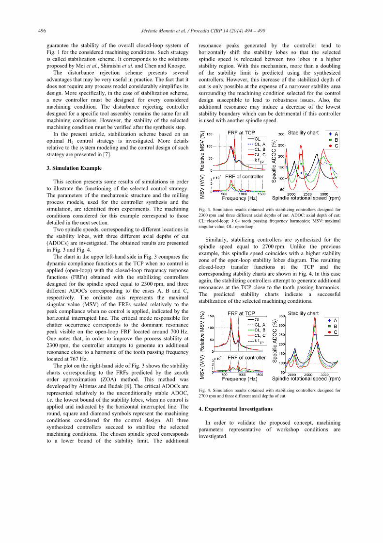
Two spindle speeds, corresponding to different locations in the stability lobes, with three different axial depths of cut (ADOCs) are investigated. The obtained results are presented in Fig. 3 and Fig. 4.
The chart in the upper left-hand side in Fig. 3 compares the dynamic compliance functions at the TCP when no control is applied (open-loop) with the closed-loop frequency response functions (FRFs) obtained with the stabilizing controllers designed for the spindle speed equal to 2300 rpm, and three different ADOCs corresponding to the cases A, B and C, respectively. The ordinate axis represents the maximal singular value (MSV) of the FRFs scaled relatively to the peak compliance when no control is applied, indicated by the horizontal interrupted line. The critical mode responsible for chatter occurrence corresponds to the dominant resonance peak visible on the open-loop FRF located around 700 Hz. One notes that, in order to improve the process stability at 2300 rpm, the controller attempts to generate an additional resonance close to a harmonic of the tooth passing frequency located at 767 Hz.
The plot on the right-hand side of Fig. 3 shows the stability charts corresponding to the FRFs predicted by the zeroth order approximation (ZOA) method. This method was developed by Altintas and Budak [8]. The critical ADOCs are represented relatively to the unconditionally stable ADOC, i.e. the lowest bound of the stability lobes, when no control is applied and indicated by the horizontal interrupted line. The round, square and diamond symbols represent the machining conditions considered for the control design. All three synthesized controllers succeed to stabilize the selected machining conditions. The chosen spindle speed corresponds to a lower bound of the stability limit. The additional
resonance peaks generated by the controller tend to horizontally shift the stability lobes so that the selected spindle speed is relocated between two lobes in a higher stability region. With this mechanism, more than a doubling of the stability limit is predicted using the synthesized controllers. However, this increase of the stabilized depth of cut is only possible at the expense of a narrower stability area surrounding the machining condition selected for the control design susceptible to lead to robustness issues. Also, the additional resonance may induce a decrease of the lowest stability boundary which can be detrimental if this controller is used with another spindle speed.
Fig. 3. Simulation results obtained with stabilizing controllers designed for 2300 rpm and three different axial depths of cut. ADOC: axial depth of cut; CL: closed-loop; k fTP: tooth passing frequency harmonics; MSV: maximal singular value; OL: open-loop.
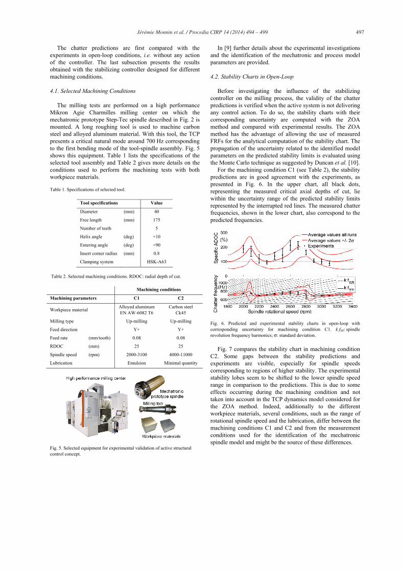
Similarly, stabilizing controllers are synthesized for the spindle speed equal to 2700 rpm. Unlike the previous example, this spindle speed coincides with a higher stability zone of the open-loop stability lobes diagram. The resulting closed-loop transfer functions at the TCP and the corresponding stability charts are shown in Fig. 4. In this case again, the stabilizing controllers attempt to generate additional resonances at the TCP close to the tooth passing harmonics. The predicted stability charts indicate a successful stabilization of the selected machining conditions.
Fig. 4. Simulation results obtained with stabilizing controllers designed for 2700 rpm and three different axial depths of cut.
4. Experimental Investigations
In order to validate the proposed concept, machining parameters representative of workshop conditions are investigated.
497 Jérémie Monnin et al. / Procedia CIRP 14 ( 2014 ) 494 – 499
The chatter predictions are first compared with the experiments in open-loop conditions, i.e. without any action of the controller. The last subsection presents the results obtained with the stabilizing controller designed for different machining conditions.
4.1. Selected Machining Conditions
The milling tests are performed on a high performance Mikron Agie Charmilles milling center on which the mechatronic prototype Step-Tec spindle described in Fig. 2 is mounted. A long roughing tool is used to machine carbon steel and alloyed aluminum material. With this tool, the TCP presents a critical natural mode around 700 Hz corresponding to the first bending mode of the tool-spindle assembly. Fig. 5 shows this equipment. Table 1 lists the specifications of the selected tool assembly and Table 2 gives more details on the conditions used to perform the machining tests with both workpiece materials.
Table 1. Specifications of selected tool.
Tool specifications Value
Diameter (mm) 40
Free length (mm) 175
Number of teeth 5
Helix angle (deg) +10
Entering angle (deg) +90
Insert corner radius (mm) 0.8
Clamping system HSK-A63
Table 2. Selected machining conditions. RDOC: radial depth of cut.
Machining conditions
Machining parameters C1 C2
Workpiece material Alloyed aluminum EN AW-6082 T6
Carbon steel Ck45
Milling type Up-milling Up-milling
Feed direction Y+ Y+
Feed rate (mm/tooth) 0.08 0.08
RDOC (mm) 25 25
Spindle speed (rpm) 2000-3100 4000-11000
Lubrication Emulsion Minimal quantity
Fig. 5. Selected equipment for experimental validation of active structural control concept.
In [9] further details about the experimental investigations and the identification of the mechatronic and process model parameters are provided.
4.2. Stability Charts in Open-Loop
Before investigating the influence of the stabilizing controller on the milling process, the validity of the chatter predictions is verified when the active system is not delivering any control action. To do so, the stability charts with their corresponding uncertainty are computed with the ZOA method and compared with experimental results. The ZOA method has the advantage of allowing the use of measured FRFs for the analytical computation of the stability chart. The propagation of the uncertainty related to the identified model parameters on the predicted stability limits is evaluated using the Monte Carlo technique as suggested by Duncan et al. [10].
For the machining condition C1 (see Table 2), the stability predictions are in good agreement with the experiments, as presented in Fig. 6. In the upper chart, all black dots, representing the measured critical axial depths of cut, lie within the uncertainty range of the predicted stability limits represented by the interrupted red lines. The measured chatter frequencies, shown in the lower chart, also correspond to the predicted frequencies.
Fig. 6. Predicted and experimental stability charts in open-loop with corresponding uncertainty for machining condition C1. k fSR: spindle revolution frequency harmonics; σ: standard deviation.
Fig. 7 compares the stability chart in machining condition C2. Some gaps between the stability predictions and experiments are visible, especially for spindle speeds corresponding to regions of higher stability. The experimental stability lobes seem to be shifted to the lower spindle speed range in comparison to the predictions. This is due to some effects occurring during the machining condition and not taken into account in the TCP dynamics model considered for the ZOA method. Indeed, additionally to the different workpiece materials, several conditions, such as the range of rotational spindle speed and the lubrication, differ between the machining conditions C1 and C2 and from the measurement conditions used for the identification of the mechatronic spindle model and might be the source of these differences.

498 Jérémie Monnin et al. / Procedia CIRP 14 ( 2014 ) 494 – 499
Fig. 7. Predicted and experimental stability charts in open-loop with corresponding uncertainty for machining condition C2.
4.3. Stability Charts in Closed-Loop
The model-based optimal stabilization control strategy is applied for both previously mentioned machining conditions. The results obtained in machining condition C1 are presented in Fig. 8. Six different spindle speed and depth of cut combinations, represented by the magenta circles and corresponding to unstable conditions in open-loop, are used to design the controller. Each chart shows the results obtained for the different controllers. The stability limits predicted by the ZOA method and represented by the interrupted and continuous lines are derived from the identified model used for the controller synthesis. The continuous blue line represents the stability limit without any action of the control loop. The interrupted red line corresponds to the predictions in closed-loop. The experimental results are indicated by the dots. The green dots correspond to stable machining conditions with or without the control action. Conversely, the red squares represent chatter conditions independent of the control action. The blue diamonds correspond to chatter conditions stabilized by the control action.
Fig. 8. Predicted stability charts and experimental results for machining condition C1 with stabilizing controller designed for different spindle speeds and axial depths of cut. ZOA: zeroth order approximation.
A general tendency to get in practice a slightly lower stabilizing performance than expected is noticeable. For instance, at 2100 rpm and 2900 rpm, the controller does not
succeed to stabilize the process up to the ADOC selected for the control design. This is especially true in the regions of higher stability due to the fact that in these regions, less dominant dynamics of the TCP more likely to be corrupted by modeling errors becomes relevant for the chatter stability. In spite of that, for all investigated spindle speeds, an effective increase of the stability limit, representative of the tendency predicted by the control design, is observable. A stability increase up to 91% is achieved at spindle speeds corresponding to a lower bound of the stability charts, i.e. at 2300 and 3100 rpm. These results confirm the validity of the proposed concept for the case of a reliable model.
The case of a less reliable model is investigated with the machining condition C2. Four different spindle speeds are selected for the control design. The results are presented in Fig. 9. The upper left-hand chart corresponds to the controller designed for a spindle speed equal to 5000 rpm. As shown in Fig. 7, at this spindle speed, the stability predictions in open-loop are in good agreement with the experiments. The results in closed-loop confirm the positive influence of the designed controller on the measured stability limit corresponding to the prediction even if the selected depth of cut cannot be stabilized. The same conclusion can be drawn from the lower right-hand side chart corresponding to a selected spindle speed equal to 11000 rpm. In this case also, even if the stabilizing influence is less than expected an increase of the critical axial depth of cut is observed corresponding to the tendency predicted by the control design.
Fig. 9. Predicted stability charts and experimental results for machining condition C2 with stabilizing controller designed for different spindle speeds and axial depths of cut.
The upper right-hand side chart indicates the results obtained with a controller designed for 9000 rpm. As visible on Fig. 7, at this spindle speed, the stability predictions give a larger critical depth of cut than the measurements do. As a result of this obvious gap between the prediction and the experiments in open-loop, a detrimental effect on the controller influence could be expected. However, the experimental results in Fig. 9 indicate a stabilizing action of the controller corresponding to the tendency predicted by the control design but shifted in lower depths of cut due to the gap with the open-loop predictions.

499 Jérémie Monnin et al. / Procedia CIRP 14 ( 2014 ) 494 – 499
The last investigated machining condition corresponds to a spindle speed equal to 7000 rpm shown in the lower left-hand side chart in Fig. 9. From the observations in open-loop, the predicted critical axial depth of cut is in accordance with the measurements. However, the corresponding chatter frequency expected around 800 Hz does not match the frequency measured at approximately 1500 Hz. This indicates that the critical mode responsible for chatter occurrence at this spindle speed is different between the prediction and the experiments. By looking at the closed-loop results presented in Fig. 9, instead of stabilizing the process as expected by the control design, the control action tends to destabilize the milling process, as represented by the black triangles, leading to a 11% reduction of the critical ADOC.
Fig. 10. Predicted and measured FRFs at TCP with stabilizing controller designed for machining condition C2 and 7000 rpm.
This negative influence can be explained by looking at the difference between the predicted and measured frequency response at the TCP presented in Fig. 10. In this figure, one notes that the influence of the controller on the TCP is quite light. Furthermore, even if the comparison of the controller influence between the prediction and the measurements are relatively similar, some frequency ranges denote non negligible gaps. In particular, in the frequency range around 1500 Hz, where the TCP dynamics seems to be determinant for the stability at 7000 rpm, the measurements indicate a light increase of the TCP flexibility while the predictions don’t. This negative effect seems to play a determinant role for the observed stability results achieved by the controller.
Fig. 11. Predicted stability charts based on measured FRFs at TCP and experimental results for machining condition C2 with stabilizing controller designed for 7000 rpm.
This is confirmed by the computation of the stability lobes diagrams in open and closed-loop based on the measured FRF at TCP and presented in Fig. 11.
5. Conclusion
The experimental results presented here demonstrate the validity of the proposed concept of active structural control for the mitigation of chatter in milling process using a mechatronic spindle combined with a model-based optimal control strategy. With this system a chatter-free productivity increase up to 91% is achieved.
Even if this concept presents a great potential, it must still face several limitations making its integration into a production environment ambitious. The system must be efficient for all spindle speeds in order to guarantee its attractiveness among other type of methods, such as active damping strategies. However, mainly because of model reliability issues, only the lower bounds of the stability lobes are satisfactorily improved. The reliability of the stability prediction in closed-loop conditions, i.e. by considering the whole dynamics of the mechatronic system interacting with the milling process over a sufficiently wide frequency range, is probably the greatest challenge that needs to be overcome.
Acknowledgements
The authors want to express their special gratitude to Step-Tec AG for its contribution in the development of the prototype spindle.
This work was supported by the Commission for Technology and Innovation (CTI) of the Federal Department of Economic Affairs of Switzerland.
References
[1] Ries M, Pankoke S. Increasing the Stability of the Milling Process by an Active Milling Spindle. Proceedings of the 1st International Conference on Process Machine Interactions 2008:95-102.
[2] Dohner J, Lauffer J, Hinnerichs T, Shankar N, Regelbrugge M, Kwan C-M, Xu R, Winterbauer B, Bridger K. Mitigation of Chatter Instabilities in Milling by Active Structural Control. J. Sound Vib. 2004;269:197-211.
[3] Mei C, Cherng J, Wang Y. Active Control of Regenerative Chatter During Metal Cutting Process. J. Manuf. Sci. Eng. 2006;128:346-349.
[4] Shiraishi M, Yamanaka K, Fujita H. Optimal Control of Chatter in Turning. Int. J. Mach. Tools Manuf. 1991;31:31-43.
[5] Chen M, Knospe C. Control Approaches to the Suppression of Machining Chatter Using Active Magnetic Bearings. IEEE Trans. Contr. Syst. Technol. 2007;15:220-232.
[6] van Dijk N, van de Wouw N, Doppenberg E, Oosterling J, Nijmeijer H. Robust Active Chatter Control in the High-Speed Milling Process. IEEE Trans. Contr. Syst. Technol. 2012;20:901-917.
[7] Monnin J, Kuster F, Wegener K. Optimal Control for Chatter Mitigation in Milling, Part 1: Modeling and Control Design. Control Eng. Pract. 2014; 24:156-166.
[8] Altintas Y, Budak E. Analytical Prediction of Stability Lobes in Milling. CIRP Ann. Manuf. Technol. 1995;44:357-362.
[9] Monnin J, Kuster F, Wegener K. Optimal Control for Chatter Mitigation in Milling, Part 2: Experimental Validation. Control Eng. Pract. 2014; 24:167-175.
[10] Ducan G, Kurdi M, Schmitz T. Uncertainty Propagation for Selected Analytical Milling Stability Limit Analysis. Transactions of NAMRI/SME 2006;34:17-24.