modeling, fabrication, and optimization of niobium
TRANSCRIPT

Transmutation Sciences Materials (TRP) Transmutation Research Program Projects
2003
Modeling, Fabrication, and Optimization of Niobium Cavities: Final Modeling, Fabrication, and Optimization of Niobium Cavities: Final
Phase Phase
Robert A. Schill Jr. University of Nevada, Las Vegas, [email protected]
Mohamed Trabia University of Nevada, Las Vegas, [email protected]
Follow this and additional works at: https://digitalscholarship.unlv.edu/hrc_trp_sciences_materials
Part of the Electrical and Computer Engineering Commons, Mechanical Engineering Commons,
Metallurgy Commons, and the Nuclear Engineering Commons
Repository Citation Repository Citation Schill, R. A., Trabia, M. (2003). Modeling, Fabrication, and Optimization of Niobium Cavities: Final Phase. 1-20. Available at:Available at: https://digitalscholarship.unlv.edu/hrc_trp_sciences_materials/3
This Grant is protected by copyright and/or related rights. It has been brought to you by Digital Scholarship@UNLV with permission from the rights-holder(s). You are free to use this Grant in any way that is permitted by the copyright and related rights legislation that applies to your use. For other uses you need to obtain permission from the rights-holder(s) directly, unless additional rights are indicated by a Creative Commons license in the record and/or on the work itself. This Grant has been accepted for inclusion in Transmutation Sciences Materials (TRP) by an authorized administrator of Digital Scholarship@UNLV. For more information, please contact [email protected].
1
Modeling, Fabrication, and Optimization of Niobium Cavities – Final Phase
Principal Investigators (PI): Robert A. Schill, Jr.Department of Electrical & Computer Engineering, UNLV4505 Maryland Parkway, Las Vegas, NV 89154-4026Phone: (702) 895-1526Email: [email protected]
Mohamed B. TrabiaDepartment of Mechanical Engineering, UNLV4505 Maryland Parkway, Las Vegas, NV 89154-4027Phone: (702) 895-0957Email: [email protected]
Investigator: William CulbrethDepartment of Mechanical Engineering, UNLV4505 Maryland Parkway, Las Vegas, NV 89154-4027Phone: (702) 895-3426Email: [email protected]
Current Students: S. Subramanian (Graduate Student)Anoop George (Graduate Student)Myong Holl (Undergraduate Student)
Collaborators (DOE): Dr. Tsuyoshi Tajima, Team LeaderAccelerator Physics & EngineeringLANSCE-1Los Alamos National LaboratoryMS H817Los Alamos, NM 87545Phone: (505) 667-6559Email: [email protected]
TRP Research Area: Accelerator / Transmutation Sciences
Budget Request: $ 161,147

2
AbstractNiobium cavities are important parts of the integrated NC/SC high-power linacs. Over the
years, researchers in several countries have tested various cavity shapes. They concluded thatelliptically shaped cells are the most appropriate shape for superconducting cavities. The needfor very clean surfaces lead to the use of a buffered chemical polishing produce for surfacecleaning to get good performance of the cavities. This is the third and final phase of the study.The first phase has resulted in improving the basic understanding of multipacting and theprocess of chemical etching. The second phase has resulted in an experimental setup of a fluidflow experiment with experimentation to be completed in the third year. Other experimentalactivities include the evaluation of a vacuum system and various vacuum equipment purchasesand modifications. An optimization code for a five cell niobium cavity based on resonantfrequency and mode number was developed. Based on our conclusions so far, as well as ourinteraction with personnel at Los Alamos National Laboratory (LANL), we propose to focus onthe following topics in the third phase of this project:
1. Optimize the cavity shape based on the desired resonant frequency and examinemultipacting of that structure.
2. Studying secondary electronic emission from a niobium test piece under cryogenicconditions.
3. Experimental study of the etching process using flow visualization techniques.4. Redesign the etching process to maximize surface uniformity.
IntroductionThe nuclear industry provides a significant percentage of the world, including the United
States, with electricity. Nuclear power plants produce thousands of tons of spent fuel. Some ofthis spent fuel can be radioactive for thousands of years. The US DOE is currently exploringthe possibility of creating a permanent storage site at Yucca Mountain, Nevada for nuclearspent fuel. Accelerator Transmutation of Waste is one complementary approach to deal withspent nuclear fuel. In this approach, a particle accelerator produces protons that react with aheavy metal target to produce neutrons. These neutrons are used to transmute long-livedradioactive isotopes into shorter-lived isotopes that are easier to be handled. A majorcomponent of the system is a linear accelerator (linac) that can accelerate a 100-mA beam ofprotons up to 1 GeV [1]. Los Alamos National Laboratory (LANL) is an active participant indeveloping a superconducting rf (SCRF) high-current linear accelerator. SCRF has three majorcomponents: niobium cavities, power couplers, and cryomodules. This proposal mainly dealswith niobium cavities.
Niobium cavities have several advantages including small power dissipation compared tonormal conducting copper cavities. These cavities are usually made of multiple elliptical cells.Refer to Figure 1. They are formed from sheet metal using various techniques such as deepdrawing or spinning. The cells then are welded using electron-beams. Multi-cell units areusually tuned by stretching or squeezing them. Niobium cavities need very clean surfaces,which can be achieved by chemical polishing and high pressure rinsing with ultra-pure water.

3
Figure 1. Schematic Diagram of Niobium Cavities (Executive Summary: Development andPerformance of Medium-Beta Superconducting Cavities (LANL))
Under operation very high electromagnetic fields are present in these cavities. Besides theintended acceleration of a particle beam, these fields can also accelerate electrons emitted fromthe niobium surfaces. An electron emitted from the surface of the cavity wall is guided andaccelerated by these RF-fields until it impacts on the cavity surface again. This re-impact canlead to the generation of one or more secondary electrons that in turn act as primary electronsthat possibly might generate more electrons in a localized region. The number of secondaryelectrons is determined by the impact energy of the electron and by the secondary emissioncoefficient of the cavity material. If secondary electrons are created in phase with the RF-fields,and the impact is localized, a rapidly rising multiplication of electrons will occur. Thislocalized resonant process is known as multipacting (multiple impacting). As a consequence,RF power is absorbed and it becomes impossible to increase the cavity fields by raising theincident power. The electron collisions with the structure walls lead to a temperature rise andeventually to a breakdown of the superconductivity. As a result, the Q0 (quality factor) of thecavity is significantly reduced at the multipacting thresholds. Also, structural damage of thesurface can occur. A good cavity design should be able to eliminate, or at least minimizemultipacting. The factors that affect multipacting include: shape, surface finish, and coating.
While models have been suggested for minimizing multipacting [2], practical means ofmanufacturing the cavity walls to obtain optimal designs are still an issue. Attempting toimprove the performance of multiple niobium cavities may be a daunting task because of thecomputational load associated with the evaluation of a particular design and the large numberof variables and constraints involved. We propose approaching this task in a systematic wayusing principles of nonlinear programming. The consequence of this effort will allow theSuperconducting RF Engineering Development and Demonstration group at LANL and thefaculty at UNLV to target potential cavity cell configurations that improve upon existingdesigns.
Summary of Achievements of Phases I and II:
1. Optimization of the shape of the cavity to produce the desired resonant frequency andmode of operation: This is a unique study with no precedent in the available literature.We have created a framework for interacting with two dimensional field codes

4
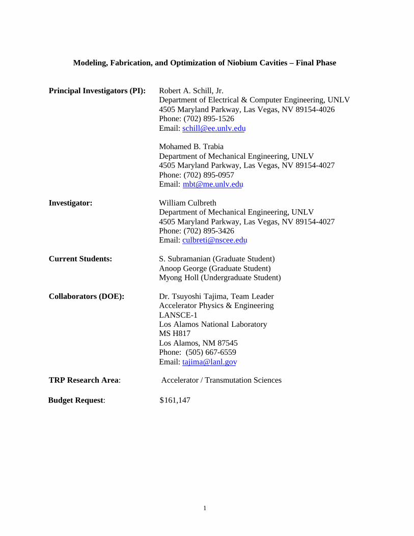
developed by Field Precision Inc. and an optimization program within a MATLABenvironment. Figure 2a illustrates the outcome of a seed geometry, Fig. 2b, as theoptimization routine hones in on the target frequency (700 MHz) and mode (pi mode).It is to be noted that the optimization process was stopped after a few days of iteration.At the time the code was terminated, the resonant frequency was approaching the target700 MHz frequency but the pi mode was not found. It is observed that as the endcavities and the end pipes terminating the five cell geometry approach the same radius,both the target resonant frequency and the pi mode constraint will be found but for athree cavity geometry system as compared to the five cavity system. This implies thatthe optimization code is properly converging but it is converging to a geometry that isnot of interest. The cavity geometry currently being employed at the LANL is illustratedin Fig. 2c. The end cells of the seed geometry (Fig. 2b) differ significantly from theexisting geometry (Fig. 2c). The optimization process is being further constrained so toconverge on a more desirable solution.
(a) Five-cell niobium cavity approaching an optimized geometry
(b) Five-cell niobium cavity seed geometry
5
(c) Five-cell niobium cavity original beta 64 LANL cavity geometryFigure 2
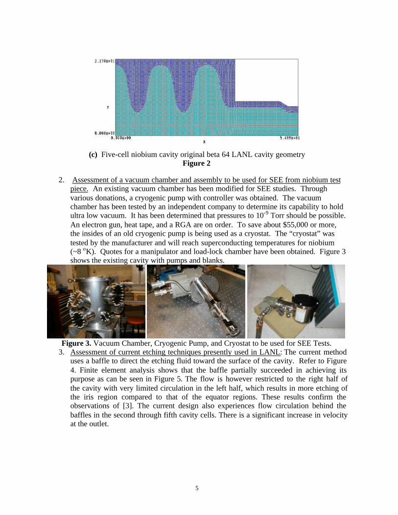
2. Assessment of a vacuum chamber and assembly to be used for SEE from niobium testpiece. An existing vacuum chamber has been modified for SEE studies. Throughvarious donations, a cryogenic pump with controller was obtained. The vacuumchamber has been tested by an independent company to determine its capability to holdultra low vacuum. It has been determined that pressures to 10-9 Torr should be possible.An electron gun, heat tape, and a RGA are on order. To save about $55,000 or more,the insides of an old cryogenic pump is being used as a cryostat. The “cryostat” wastested by the manufacturer and will reach superconducting temperatures for niobium(~8 oK). Quotes for a manipulator and load-lock chamber have been obtained. Figure 3shows the existing cavity with pumps and blanks.
Figure 3. Vacuum Chamber, Cryogenic Pump, and Cryostat to be used for SEE Tests.
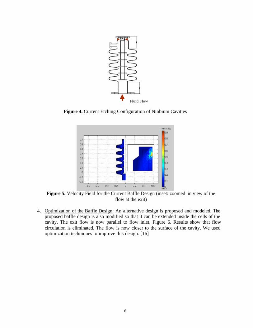
3. Assessment of current etching techniques presently used in LANL: The current methoduses a baffle to direct the etching fluid toward the surface of the cavity. Refer to Figure4. Finite element analysis shows that the baffle partially succeeded in achieving itspurpose as can be seen in Figure 5. The flow is however restricted to the right half ofthe cavity with very limited circulation in the left half, which results in more etching ofthe iris region compared to that of the equator regions. These results confirm theobservations of [3]. The current design also experiences flow circulation behind thebaffles in the second through fifth cavity cells. There is a significant increase in velocityat the outlet.
6
Figure 4. Current Etching Configuration of Niobium Cavities
Figure 5. Velocity Field for the Current Baffle Design (inset: zoomed–in view of theflow at the exit)
4. Optimization of the Baffle Design: An alternative design is proposed and modeled. Theproposed baffle design is also modified so that it can be extended inside the cells of thecavity. The exit flow is now parallel to flow inlet, Figure 6. Results show that flowcirculation is eliminated. The flow is now closer to the surface of the cavity. We usedoptimization techniques to improve this design. [16]
Fluid Flow
7
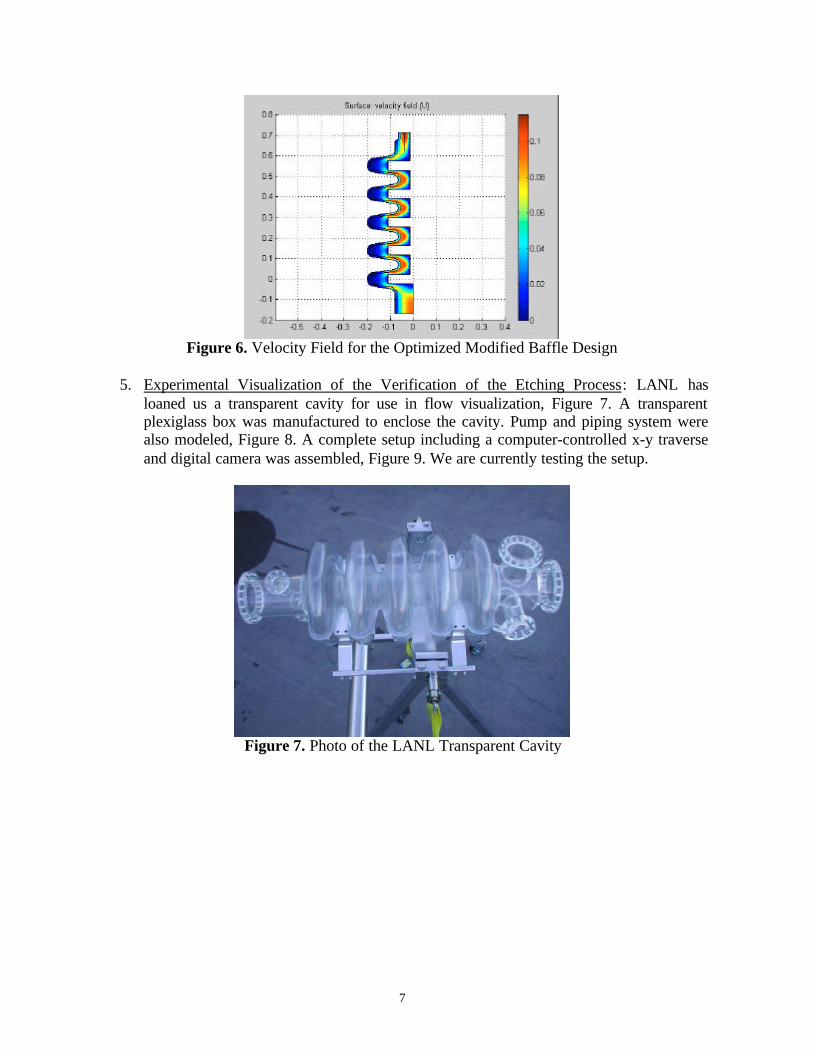
Figure 6. Velocity Field for the Optimized Modified Baffle Design
5. Experimental Visualization of the Verification of the Etching Process: LANL hasloaned us a transparent cavity for use in flow visualization, Figure 7. A transparentplexiglass box was manufactured to enclose the cavity. Pump and piping system werealso modeled, Figure 8. A complete setup including a computer-controlled x-y traverseand digital camera was assembled, Figure 9. We are currently testing the setup.
Figure 7. Photo of the LANL Transparent Cavity

8
Figure 8. A Model of the Experimental Setup
Figure 9. A Model of the Experimental Setup
6. These research activities are disseminated through:• One paper that was presented in the International Congress on Advanced Nuclear
Power Plants (ICAPP), Hollywood, Florida, June 2002. The title of the paper is,“Modeling and Optimization of the Chemical Etching Process in Niobium Cavities.”
• Discussions with LANL personnel, especially Dr. Tsuyoshi Tajima.• Abstract accepted at the American Nuclear Society, Accelerator Applications
Division, AccApp’03,“Accelerator Applications in a Nuclear Renaissance”, SanDiego, California – June 1-5, 2003. Abstract entitled: Optimization of a Five CellNiobium Cavity. [Abstract No. 79389]

9
Research ObjectivesThe research objectives are:
1. Continue current research on the phenomenon of multipacting.2. Optimize the shape of the cavity based on the desired resonant frequency and mode and
examine multipacting properties.3. Experimentally study of secondary electron emission from a niobium piece (1 cm2) that
has been surface-conditioned by LANL.4. Use the flow visualization experimental setup to evaluate flow patterns of the etching
fluid inside a plastic model of the niobium cavity with various baffle designs.5. Redesign the etching process to maximize surface uniformity by considering the effects
of rotating the baffle within the cavity.
Technical ImpactThe proposed work will make a major contribution to the understanding and design of
niobium cavities. This area is very critical with many recent developments, e.g. [4], [5], and[6]. The proposed research will provide a means to benchmark the codes for LANL specificobjectives. To our knowledge, few if any studies have examined secondary electron emissionof niobium in the superconducting state. It is believed that the physics of the material is fardifferent in this state as compared to that at room temperature. Also, empirical data obtainedfrom experiments will be incorporated into the Track_RF code. The proposed research willresult in a method for optimal design of superconducting RF-resonators. Our research is multi-disciplinary, combining expertise from three distinct areas (electromagnetics, fluid dynamics,and optimization). Graduate students involved in this project will be exposed to these threeareas and will be expected to work as a team. It is expected that this interaction will result inseveral publications gaining recognition of UNLV activities in this area as well as attractingadditional funds to the university.
It is anticipated that the developed modeling tool will impact the efficiency of futuresuperconducting cavity designs of interest to the Superconducting RF EngineeringDevelopment and Demonstration (SRFEDD) group at LANL and elsewhere. Such a study willguide the (SRFEDD) group and their UNLV collaborators to establish fabrication strategies formanufacturing. These efforts should also lay the foundation for examining multipacting in RFwindows in the future.
Research ApproachThe proposed research can be divided into several interconnected tasks as shown in Figure
10. The remainder of this section details our approach to each task.

10
Multipacting
Optimal Design of theNiobium Cavities
CFD Study ofChemical Etching
Experimental Studiesof Multipacting
Experimental Studiesof Chemical Etching
Figure 10. Research Tasks
Task 1. MultipactingNumerical models of multipacting are of great interest for the design of RF cavities for high
energy proton accelerators. Multipacting is a resonant phenomena of an electron avalanche asa result of localized impact due to secondary electron emission. The growth of a localizedcurrent originating and terminating on the cavity wall absorbs and dissipates a part of theelectromagnetic energy stored in the cavity. Multipacting lowers the Q0 of the cavity limitingthe energy stored by the cavity. It can also cause damage to the RF-surface. By conditioningthe cavity (operating the RF cavity at its highest achievable field level in the absence of thebeam), soft barrier healing of the cavity may be possible lowering the secondary emissioncoefficient. This may be a time intensive process. The shape of the cavity structure, itsmaterial composition, and the surface treatment play significant roles in mitigating multipactingprocesses. It has been shown that cavities with a more circular wall geometry along the cavityaxis inhibits multipacting relative to elliptical cavities, [7]. The SEE (Secondary ElectronEmission) curve for niobium at room temperature is well known. Even so, multipacting isdependent of the surface treatment of the cavity. Different niobium surface treatments can alterthe SEE coefficient by nearly a factor of three, [8]. This is significant since niobium has amaximum SEE coefficient of 1.1 at an electron impact energy of about 500 eV. Further, thesurface treatments examined in 1986, [8], are not necessarily the same types of treatmentscurrently used on superconducting cavities at LANL. Moreover, it is known that surfacekinetics plays a significant role in the secondary emission. Besides the impact energy, also theimpact angle may have to be considered for proper modeling, [9]. In practice, the niobiumcavities are operated at cryogenic temperatures yielding a superconducting state. Little to noinformation is readily available on the SEE in this state. It is anticipated that the SEEcoefficient will be different than that at room temperature. This is because the physics ofsuperconductors at cryogenic temperatures dictates that the electric force on charges is onlybalanced only by their inertia since charge collisions within the material are negligible to zero.Therefore, as an electron approaches the superconducting material, conduction electrons will beCoulomb repelled within the material away from the point of impact. Secondary electronsemitted from the site of impact may require more energy to be emitted from the surface as aresult compared to room temperature niobium. It is therefore of interest to study the niobiummaterial in the state similar to that in the accelerator.
11
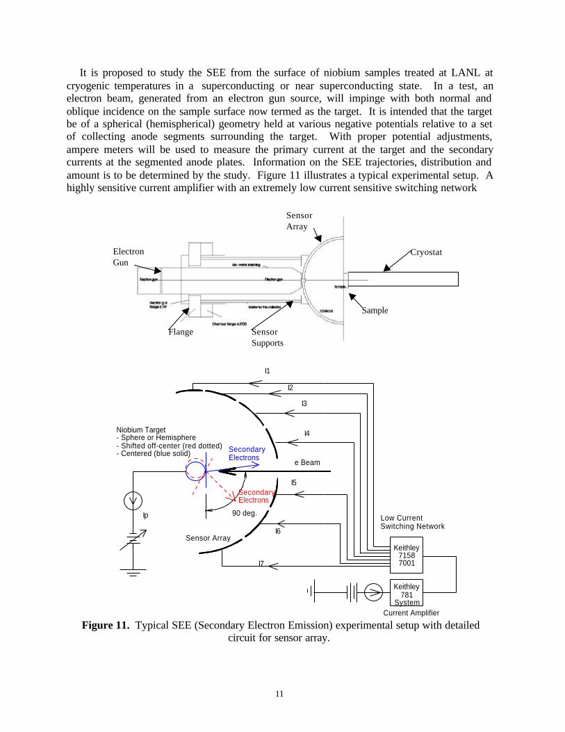
It is proposed to study the SEE from the surface of niobium samples treated at LANL atcryogenic temperatures in a superconducting or near superconducting state. In a test, anelectron beam, generated from an electron gun source, will impinge with both normal andoblique incidence on the sample surface now termed as the target. It is intended that the targetbe of a spherical (hemispherical) geometry held at various negative potentials relative to a setof collecting anode segments surrounding the target. With proper potential adjustments,ampere meters will be used to measure the primary current at the target and the secondarycurrents at the segmented anode plates. Information on the SEE trajectories, distribution andamount is to be determined by the study. Figure 11 illustrates a typical experimental setup. Ahighly sensitive current amplifier with an extremely low current sensitive switching network
Figure 11. Typical SEE (Secondary Electron Emission) experimental setup with detailedcircuit for sensor array.
Flange
ElectronGun
SensorArray
Cryostat
Sample
SensorSupports
Keithley781
SystemCurrent Amplifier
e Beam
I4Niobium Target- Sphere or Hemisphere- Shifted off-center (red dotted)- Centered (blue solid)
Sensor Array
Ip
I7
I6
SecondaryElectrons
90 deg.
SecondaryElectrons
I5
I3
I1
I2
Low CurrentSwitching Network
Keithley71587001
12
will be used to amplify and convert the current signals to measurable voltage signals. Thetarget under test must be held at cryogenic temperatures in a vacuum environment; ~10-8 to 10-9
Torr. Studying the distribution of the SEE will give a clue on how to statistically handlechanges in the grain structure of the material. Experimental conditions similar to that in RFsuperconducting cavities are sought.
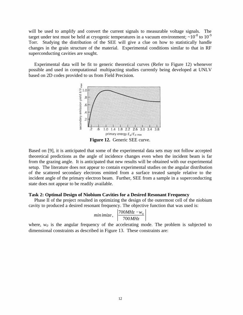
Experimental data will be fit to generic theoretical curves (Refer to Figure 12) wheneverpossible and used in computational multipacting studies currently being developed at UNLVbased on 2D codes provided to us from Field Precision.
Figure 12. Generic SEE curve.
Based on [9], it is anticipated that some of the experimental data sets may not follow acceptedtheoretical predictions as the angle of incidence changes even when the incident beam is farfrom the grazing angle. It is anticipated that new results will be obtained with our experimentalsetup. The literature does not appear to contain experimental studies on the angular distributionof the scattered secondary electrons emitted from a surface treated sample relative to theincident angle of the primary electron beam. Further, SEE from a sample in a superconductingstate does not appear to be readily available.
Task 2: Optimal Design of Niobium Cavities for a Desired Resonant FrequencyPhase II of the project resulted in optimizing the design of the outermost cell of the niobium
cavity to produced a desired resonant frequency. The objective function that was used is:
MHzMHz
,imizemin700
700 0ω−
where, ω0 is the angular frequency of the accelerating mode. The problem is subjected todimensional constraints as described in Figure 13. These constraints are:
13
88
77
66
55
44
33
22
11
BA
BABrA
Bba
A
BxA
BbyABLxA
BryA
L
a
a
e
e
e
ee
oe
aa
≤≤
≤≤≤≤
≤≤
≤≤
≤−≤≤+≤
≤+≤
φ
φ
The optimization algorithm used in this problem is Fuzzy Simplex [13], which incorporatesfuzzy logic to make the simplex search flexible. Results, Figures 2a-c, show that theoptimization search radically modified the design of the cell. The next stage is to incorporatethe inner cells into the process. Similar set of constraints will be added to represent these cells.The final design will be assessed to ensure that multipacting is minimized.
There are a number of criteria that need to be considered, when optimizing niobiumcavities. The most important ones are the quality factor, Q0 [2] and the ratios of peak surfacefields to the average accelerating field in the cavity. As a first step in optimizing the niobiumcavities the quality factor is used as a performance measure. It is defined as
cPU
Q 00
ω=
where, U is the stored energy and Pc is the power both dissipated in the cavity walls andabsorbed by the multipacting electrons, and ω0 is the angular frequency of the acceleratingmode. The peak field ratios will be considered according to a strategy that will be defined incollaboration with LANL. The above equation shows that minimizing the lost energy andmaximizing the stored energy can maximize the quality factor. An alternative measure ofmultipacting used is the global multipacting factor, [11], which is the averaging over the totalnumber of initially emitted electrons over the distributed cavity surface,
( )∏=
k
mmKN
10 δ
Because we are optimizing the geometry of the cavity to reduce or eliminate multipacting, theabove measure will be modified to monitor multipacting at localized regions on the cavitysurface. To take into consideration that secondary electrons may be responsible for initiatingmultipacting, a number of particles with varying phase will be launched at positions where thesecondary electron emission is greater than unity. This will allow us to artificially tracksecondary electrons that may potentially cause multipacting.

14
Figure 13. Variables that Describe the Cavity
Task 3: Optimal Design of the Etching ProcessThe ultimate goal of the primary optimization is a cavity shape that fulfills all mechanical
and RF requirements. The optimization of the chemical etching will be conducted for thiscavity design. The velocity of the flow should be as uniform as possible in the case of laminarflow to ensure a uniform etching. Velocity distribution will allow mass transfer rates to becalculated to determine etching rates of the surface.
Task 4: Redesign the Etching Process to Maximize Surface UniformityThe surface finish of the niobium cavity plays an important role for achieving the best
performance. Even microscopic contaminants on the surface of the cavity can seriously affectits performance due to magnetic heating or electron field emission. As a consequence, a surfacefinish treatment is needed after fabrication of the cavity. Studies in the first phase of this projectusing computational fluid dynamics (CFD) helped in better understanding the process. Ourpreliminary studies also showed that the quality of etching could be further improved. Wepropose to look at several questions during this phase of the project including:
1. Redesign of the Baffle2. Study the effect of turbulence on etching3. Flow visualization
The remainder of this section details the proposed approach for these subtasks.
4.1. Redesign of the Baffle:As seen in an earlier section, we already started the process of redesigning the baffle. The
new design results in a more laminar flow (Figure 6) which may be achieved by extending the
ra
φa
ya
φL
L
(xe,ye)
Lo
ae: minor radiusof the ellipsebe: major radiusof the ellipse
15
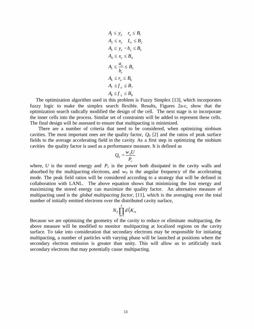
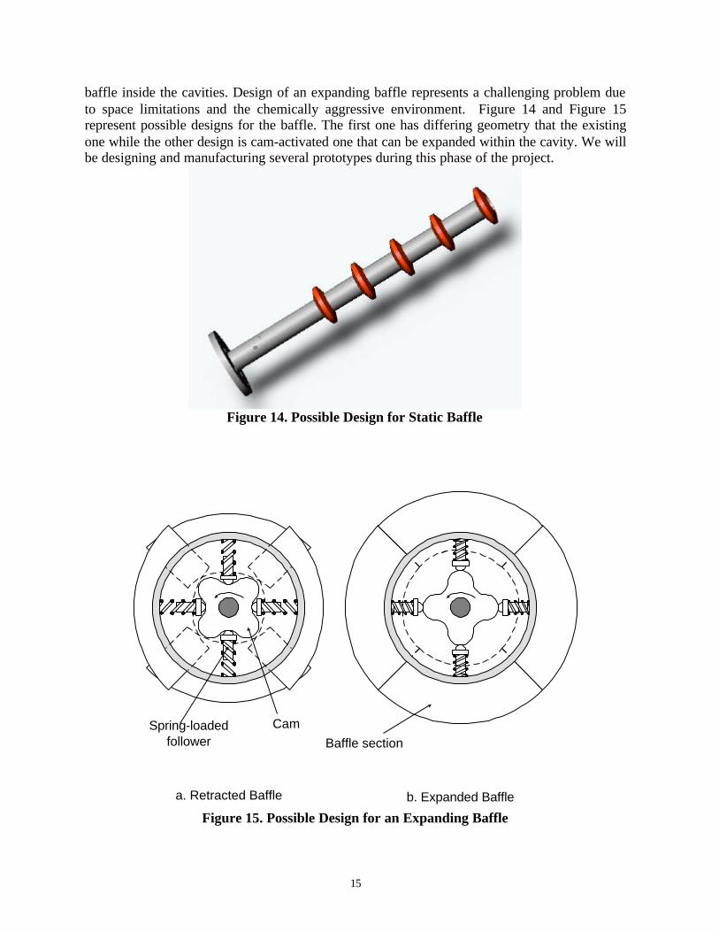
baffle inside the cavities. Design of an expanding baffle represents a challenging problem dueto space limitations and the chemically aggressive environment. Figure 14 and Figure 15represent possible designs for the baffle. The first one has differing geometry that the existingone while the other design is cam-activated one that can be expanded within the cavity. We willbe designing and manufacturing several prototypes during this phase of the project.
Figure 14. Possible Design for Static Baffle
a. Retracted Baffle b. Expanded Baffle
Baffle sectionCamSpring-loaded
follower
Figure 15. Possible Design for an Expanding Baffle
16
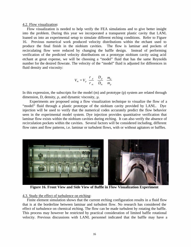
4.2. Flow visualization:Flow visualization is needed to help verify the FEA simulations and to give better insight
into the problem. During this year we incorporated a transparent plastic cavity that LANLloaned us into an experimental setup to simulate different etching conditions. Refer to Figure16. Previous numerical work produced velocity distributions within the etchant used toproduce the final finish in the niobium cavities. The flow is laminar and pockets ofrecirculating flow were reduced by changing the baffle design. Instead of performingverification of the predicted velocity distributions on a prototype niobium cavity using acidetchant at great expense, we will be choosing a “model” fluid that has the same Reynoldsnumber for the desired flowrate. The velocity of the “model” fluid is adjusted for differences influid density and viscosity:
=
p
m
m
p
m
ppm D
DVV
µµ
ρ
ρ
In this expression, the subscripts for the model (m) and prototype (p) system are related throughdimension, D, density, ρ, and dynamic viscosity, µ. Experiments are proposed using a flow visualization technique to visualize the flow of a“model” fluid through a plastic prototype of the niobium cavity provided by LANL. Dyeinjection will be used to verify that the numerical codes accurately predict the flow behaviorseen in the experimental model system. Dye injection provides quantitative verification thatlaminar flow exists within the niobium cavities during etching. It can also verify the absence ofrecirculation pockets within the cavities. Several factors will be considered including, differentflow rates and flow patterns, i.e. laminar or turbulent flows, with or without agitators or baffles.
Figure 16. Front View and Side View of Baffle in Flow Visualization Experiment
4.3. Study the effect of turbulence on etching:Finite element simulation shows that the current etching configuration results in a fluid flow
that is at the borderline between laminar and turbulent flow. No research has considered theeffect of turbulence on chemical etching. The flow can be made turbulent by rotating the baffle.This process may however be restricted by practical consideration of limited baffle rotationalvelocity. Previous discussions with LANL personnel indicated that the baffle may have a
17
rotational speed of 10 rps. CFD simulation of the process will be conducted to assess theusefulness of turbulent flow.
Capabilities at the University and Los Alamos:
LANL is already active in the area of designing SCRF cavities. Lab personnel havecollaborated with US industry in the area of cavity fabrication. Some of the research facilitiesneeded to pursue this project are available at UNLV.
Equipment Requested for AAA User Labs:• Secondary Electron Emission Experiment : A switching network is required to minimized
the number of ampmeters and current amplifiers needed to measure the currents resultingfrom secondary electron emission. The currents generated as a result of SEE will be verysmall and need to be amplified. A special current amplifier is needed for the study. Inorder to move the niobium piece under test in situ, a manipulator arm with load-lockchamber is needed. The following hardware is needed for implementing SEEexperiments: flanges and pipe connections, high voltage feed-throughs, overall clean-upand maintenance cost, pressure gauges, materials for building electrode system, cryogenicfeed-throughs.
• CFD simulation of chemical etching: We are using FEMLAB (plus Chemical EngineeringModule) and MATLAB for this purpose. We have licenses for one year. Softwarelicenses will need to be updated.
• Redesign of the Baffle: Materials are required for creating different prototypes.• Flow Visualization: Dyes and seeding particles are needed in support of fluid flow
experiments. Additional equipment such as pumps, pipes, and fittings may be needed ifthe experimental setup is to be modified.
Project Timeline:Timeline NarrativeThe proposed research is planned to cover one year, starting in Summer 2003. Research will beconducted with close interaction with appropriate personnel at LANL.
Expected Technical Results:
• Secondary Electron Emission results for niobium material.• Optimization code based on the resonant frequency of the cavity and pi mode operation.• New baffle design.• Flow visualization in modeled cavity structure.
Milestones (Based on starting date of May 15th, 2003)
• Have a working optimization code based on the cavity resonance. September 2003.• Complete fluid flow experiments. September 2003• Ordered most of the vacuum equipment and assemble vacuum system. September 2003• Finish thesis on fluid flow studies December 2003
18
• Complete SEE experiments February 2004• Incorporate SEE results in multipacting code. May 2004• Complete thesis on SEE by May 2004.
Note: Researchers will produce quarterly progress reports to help monitor the progress of theproject.
DeliverablesIn addition to the quarterly and final reports, researchers expect to publish the results of this
project at the appropriate technical conferences and journals. This project will lead to M.S.theses for the graduate students participating in this project. Final report due April 2004.
References[1] “A Roadmap for Developing Accelerator Transmuting of Waste (ATW) Technology,”
DOE/RW-0519, October 1999.[2] Hasan Padamsee, Jens Knobloch, and Tom Hays, RF Superconductivity for Accelerators ,
Wiley Interscience Publication, John Wiley, N.Y. 1998.[3] B. Aune et al., “The Superconducting TESLA Cavities,”
http://documents.cern.ch/archive/electronic/physics/0003/0003011.pdf[4] P. Kneisel et al., Nuclear Instrumentation Methods Physical Resources, 188 (1981) p. 669.[5] Q. Shu et al., “Highest performance of TESLA 9-cell superconducting RF cavities by
overcoming quenches in superfluid Lhe,” IEEE Transactions on Applied Superconductivityv 7, n 2, p 371-374, 1997.
[6] P. Kneisel, “High gradient superconducting niobium cavities a review of the presentstatus,” IEEE Transactions on Applied Superconductivity v 9, n 2, p 1023-1029, 1999.
[7] U. Kelin and D. Proch in Proceedings of the Conference of Future Possibilities for ElectronAccelerators, Charlottesville, pp. N1-17 (1979).
[8] R. Calder et al., Nuclear Instrumentation Methods Physics Res. B, Beam Interaction Matter.At., 13:631 (1986).
[9] R.E. Kirby and F.K. King, “Secondary Electron Emission Yields from PEP-II AcceleratorMaterials,” SLAC-PUB-8212, October 2000.
[10] P.A. Tipler, Foundations of Modern Physics, Worth, 1969, p. 128.[11] S. Humpheries, and D. Rees, “Electron Multipactor Code for High-Power RF Devices,”
Proceedings of PAC 97, Vancouver, Canada.[12] Field Precision Finite Element Software for Magnetic and Electric Field Analysis,
http://www.fieldp.com/.[13] Trabia, M. and X. Lu, "A Fuzzy Adaptive Simplex Search Optimization Algorithm,"
ASME Journal of Mechanical Design, June 2001, pp. 216-225.[14] Mekhilef, M., and M. Trabia, “Successive Twinkling Simplex Search Optimization
Algorithms,” ASME 27th Design Automation Conference, Pittsburgh, Pennsylvania,September 2001.
[15] Ceylan, Z., and M. Trabia, “Optimization of the Closure-Weld Region of CylindricalContainers for Long-Term Corrosion Resistance,” ASME 27th Design AutomationConference, Pittsburgh, Pennsylvania, September 2001.
19
[16] S. Subramanian, Q. Xue, M. Trabia, Y. Chen, and R. Schill, “Modeling and Optimizationof the Chemical Etching Process in Niobium Cavities,” International Congress onAdvanced Nuclear Power Plants (ICAPP), Hollywood, Florida, June 2002.

37
Appendix: A. Copy of Support Letter from Dr. Tsuyoshi Tajima, Team Leader AcceleratorPhysics & EngineeringLANSCE-1, LANL