modeling full-scale blast heave with three … · modeling full-scale blast heave with...
TRANSCRIPT
MODELING FULL-SCALE BLAST HEAVE WITH THREE-DIMENSIONAL DISTINCT ELEMENTS AND PARALLEL PROCESSING 26 August 2015 Dale S. Preece, PhD, Senior Research Fellow and Manager Blasting Apps NA/EMEA Ayman Tawadrous, PhD, Consultant Stewart A. Silling, PhD, Distinguished Member of Technical Staff, Sandia National Labs Brandon Wheeler, Graduate Engineer
FRAGBLAST11

© Orica Limited Group 2
Outline • DMC-3D Computer Code Basics Parallel Processing Ore/Waste Separation and Dillution Similations Hundreds of Blastholes Millions of Particles Accurate Treatment of Delay Timing
• Quantifying Ore Waste and Dilution Overlay sphere array with Hexahedrons Sort Ore and Waste particles
• Conclusions
© Orica Limited Group 3
PREECE EQUATION
FUN = 𝑵𝑵𝑵𝑵𝑵𝑵𝑵𝑾𝑵𝑾𝑾

© Orica Limited Group 4
ORICA NA “MATRIX” COMPUTER LAB
© Orica Limited Group 5
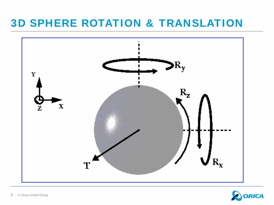
3D SPHERE ROTATION & TRANSLATION

© Orica Limited Group 6
INTERACTION OF 3D SPHERES

© Orica Limited Group 7
DMC-3D - SPHERICAL PARTICLE INTERACTION

© Orica Limited Group 8
DMC-3D PARALLEL PROCESSING
150 Blastholes, 1,68 million three-dimensional spherical elements

© Orica Limited Group 9
BLASTHOLE DELAY TIMES ROW ON ROW DELAY TIMING
Note: Circles show area of influence instead of blasthole diameter
© Orica Limited Group 10
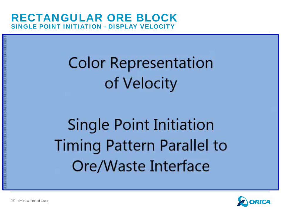
RECTANGULAR ORE BLOCK SINGLE POINT INITIATION - DISPLAY VELOCITY
© Orica Limited Group 11
RECTANGULAR ORE BLOCK SINGLE POINT INITIATION - DISPLAY ORE
© Orica Limited Group 12
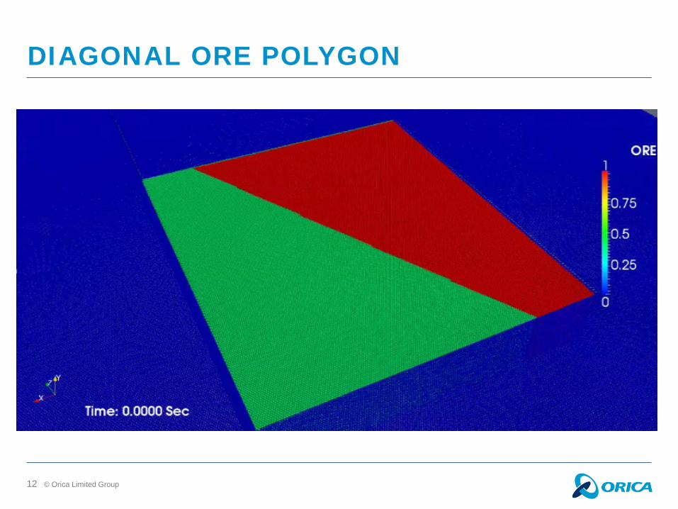
DIAGONAL ORE POLYGON

© Orica Limited Group 14
DIAGONAL ORE BLOCK SINGLE POINT INITIATION - DISPLAY ORE

© Orica Limited Group 15
RECTANGULAR ORE POLYGON ORE/WASTE SEGREGATION TIMING
Two Point Initiation
© Orica Limited Group 16
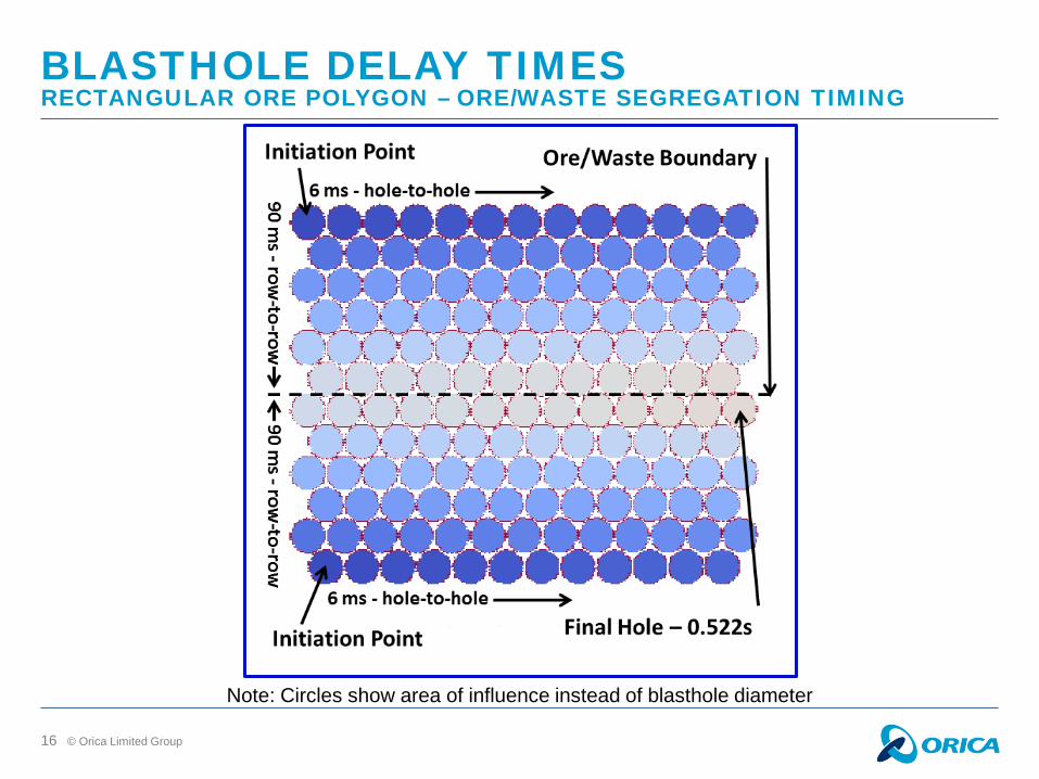
BLASTHOLE DELAY TIMES RECTANGULAR ORE POLYGON – ORE/WASTE SEGREGATION TIMING
Note: Circles show area of influence instead of blasthole diameter

© Orica Limited Group 17
RECTANGULAR ORE BLOCK DUAL POINT INITIATION - DISPLAY VELOCITY
© Orica Limited Group 18
RECTANGULAR ORE BLOCK DUAL POINT INITIATION - DISPLAY ORE

© Orica Limited Group 19
DIAGONAL ORE POLYGON ORE/WASTE SEGREGATION TIMING
Two Point Initiation
© Orica Limited Group 20
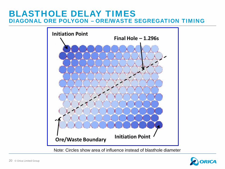
BLASTHOLE DELAY TIMES DIAGONAL ORE POLYGON – ORE/WASTE SEGREGATION TIMING
Note: Circles show area of influence instead of blasthole diameter
© Orica Limited Group 21
DIAGONAL ORE BLOCK DUAL POINT INITIATION - DISPLAY VELOCITY

© Orica Limited Group 22
DIAGONAL ORE BLOCK DUAL POINT INITIATION - DISPLAY ORE
© Orica Limited Group
23
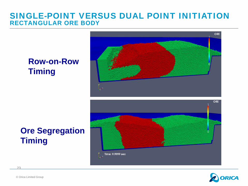
SINGLE-POINT VERSUS DUAL POINT INITIATION RECTANGULAR ORE BODY
Row-on-Row Timing
Ore Segregation Timing
© Orica Limited Group 24
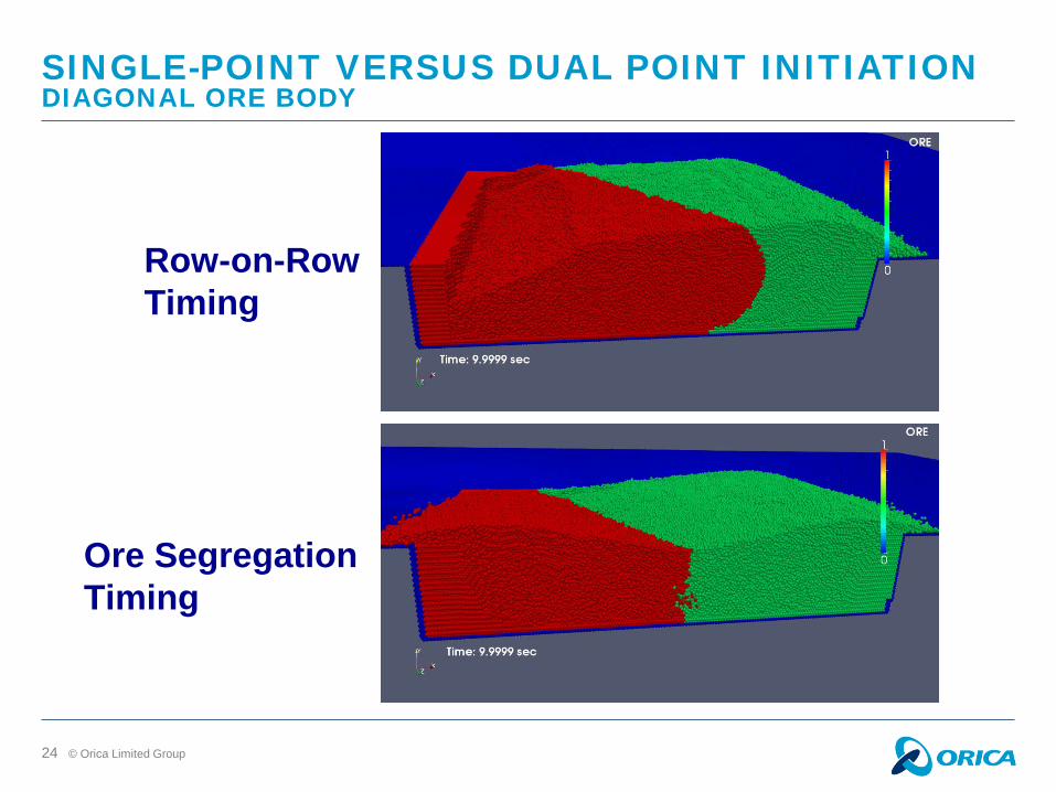
SINGLE-POINT VERSUS DUAL POINT INITIATION DIAGONAL ORE BODY
Row-on-Row Timing
Ore Segregation Timing

© Orica Limited Group 25
DMC-3D COMPUTATION TIMES Single Processor Version CPU Efficiency = 1.81 CPUs/particle
Parallel Processor Version ( Beginning with a thorough efficiency study & improvem = > speedup = 24) Four Processors: Real Time Treated = 10 s Number of Particles = ~1.67 million CPU Time = 20 hours = 72,000 CPUs CPU Efficiency = 0.0431 CPUs/particle Speedup = 1.81/0.0431 = 42

© Orica Limited Group
1,679,534 spheres
248,561 hexahedrons
26
QUANTIFYING ORE WASTE AND DILUTION DIAGONAL ORE POLYGON
Create a hexahedron mesh occupying the same space as the displaced spheres
At initial and final times: • Sort spheres into hex’s • In each hex determine:
1. Total number of spheres 2. Total number of ore spheres

© Orica Limited Group 27
QUANTIFYING ORE WASTE AND DILUTION DIAGONAL ORE POLYGON
Geometry threshold plots of %ore Color for %ore
Geometry Threshold Plots of %waste Color for %Ore

© Orica Limited Group 28
QUANTIFYING ORE WASTE AND DILUTION ASSUMING NO POST-BLAST MOVEMENT OF ORE POLYGON
Ore Wasted = 22.9%

© Orica Limited Group 29
QUANTIFYING ORE WASTE AND DILUTION ASSUMING NO POST-BLAST MOVEMENT OF ORE POLYGON
Segregation Delay Timing
Geometry threshold plot of %ore Color for %ore
Geometry threshold plot of %ore wasted Color for %ore
Ore Wasted = 2.9 %
Diagonal Ore Polygon

© Orica Limited Group 30
QUANTIFYING ORE WASTE AND DILUTION ASSUMING NO POST-BLAST MOVEMENT OF ORE POLYGON
Geometry threshold plot of %ore Color for %ore
Geometry threshold plot of %ore wasted Color for %ore
Ore Wasted = 30.2 %
Geometry threshold plot of %ore diluted Color for %ore
Ore Diluted = 25.7 %
Total Ore Loss = 30.2 + 25.7 = 55.9%
Row-on-Row Delay Timing
Rectangular Ore Polygon
© Orica Limited Group 31
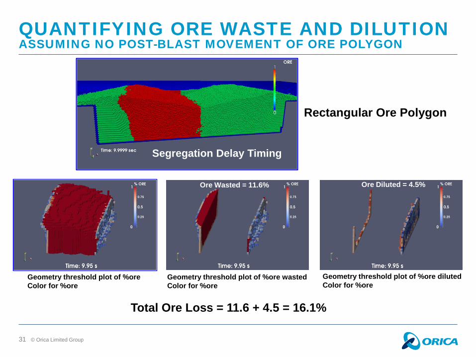
QUANTIFYING ORE WASTE AND DILUTION ASSUMING NO POST-BLAST MOVEMENT OF ORE POLYGON
Segregation Delay Timing
Rectangular Ore Polygon
Geometry threshold plot of %ore Color for %ore
Ore Wasted = 11.6%
Geometry threshold plot of %ore wasted Color for %ore
Ore Diluted = 4.5%
Geometry threshold plot of %ore diluted Color for %ore
Total Ore Loss = 11.6 + 4.5 = 16.1%

© Orica Limited Group 32
CONCLUSIONS
3D Distinct Element Parallel Processor Modelling of Rock Movement is Becoming Available for Routine Use: 42 times faster than single processor version Must be run on a multi-processor server Sculpting of muck in mineral blasting Blast Designs for ore/waste segregation
substantially reduce ore waste and dilution Quantifying ore waste and/or dilution for
different delay timing patterns

© Orica Limited Group 33
FUTURE WORK
Run DMC-3D-Parallel on other common blasting patterns
and quantify ore waste and dilution Echelon V Patterns Perpendicular to Strike
Move the Ore Polygon after Blasting for processing ore waste and dilution
Run code on more complex ore polygons and quantify
ore waste and dilution The ore polygon algorithm can accomodate any
complexity Couple MBF (Multiple Blasthole Fragmentation) with
DMC-3D-Parallel