modeling of block-based dsp systems - … of block-based dsp systems dong-ik ko and shuvra s....
TRANSCRIPT

MODELING OF BLOCK-BASED DSP SYSTEMSDong-Ik Ko and Shuvra S. Bhattacharyya
Department of Electrical and Computer Engineering, and Institute for Advanced Computer Studies
University of Maryland, College Park, 20742, USA
ABSTRACT
Modeling semantics based on dataflow graphs are used widely in design tools for digital signal
processing (DSP). This paper develops efficient techniques for representing and manipulating
block-based operations in dataflow-based DSP design tools. In this context, a block refers to a
finite-length sequence of data items, such as a sequence of speech samples, an image, or a group
of video frames, as part of an enclosing data stream. We develop in this paper a meta-modeling
technique called blocked dataflow (BLDF) for augmenting DSP design tools with more effective
blocked data support in an efficient and general manner. We compare BLDF against alternative
modeling approaches through a detailed case study of an MPEG 2 video encoder system.
KEYWORDS: DSP software synthesis, dataflow modeling, memory management, quasi-static
scheduling.
1. INTRODUCTION
In the digital signal processing (DSP) domain, rapid prototyping tools based on coarse-grain data-
flow semantics are widely used [2]. One important requirement in these tools is support for block-
based processing, such as that involved in image and video applications. We develop in this paper
a blocked dataflow (BLDF) modeling approach for efficient handling of block-based data in data-
flow-based DSP design tools. BLDF combines meta-modeling, block-based processing, multidi-
mensional representation, and dynamic parameter reconfiguration in a single, unified framework
that leads to more efficient dataflow graphs for scheduling and software synthesis.
In this paper, by a dataflow model of computation (dataflow MoC), we mean a programming
model based on dataflow semantics. Programs in a dataflow MoC are thus represented as directed
graphs in which vertices, called dataflow actors, represent computational tasks, and edges repre-
sent logical FIFO communication channels between tasks.
A decidable dataflow model is one in which deadlock and unbounded buffer accumulation
can be determined in finite time for every specification in the model. Examples of decidable data-
flow models are CSDF [3], SDF [8], MDSDF [9] and SSDF [12]. For consistent specifications in
each of these models, there is a unique, integer-valued repetitions vector that is indexed by the
graph actors and gives the number of times each actor needs to be invoked to form a minimal peri-
odic schedule for the graph.
A number of efforts have examined block processing at the level of individual actors. The
objective in such vectorization is to improve throughput and reduce context-switching overhead
by executing actors many times in succession. The scalable synchronous dataflow (SSDF) [12]
model formalized this concept in the context of multirate dataflow graphs, and algorithms have
been developed to extract the maximum vectorization potential from an SSDF graph [11]. More
recently, retiming techniques have been explored for manipulating homogeneous dataflow graphs
(graphs in which the production and consumption parameters are all equal to one) to improve vec-
torizability [6]. BLDF differs from these approaches in its applicability beyond the level of indi-
vidual actors, and into arbitrary subsystems at any level of the modeling hierarchy. BLDF also
differs in its close integration with parameterized dataflow semantics [1], which allows for power-
ful dynamic reconfiguration capabilities.
As dataflow modeling alternatives emerge further it is highly desirable to identify new mod-
eling features that can be achieved through novel applications of existing models rather than
defining a totally new dataflow variant for each new extension. This promotes reuse and integra-
tion rather than reinvention of the growing body of knowledge on established dataflow styles.
BLDF adheres to this approach by defining general mechanisms that can be used to augment
existing dataflow models with systematic data grouping capabilities. It is in this sense that we
refer to BLDF as a meta-model. BLDF can be used with the well-known decidable dataflow mod-
els, SDF, CSDF, MDSDF, and SSDF, as described above. Its use with other, more dynamic mod-
els such as boolean dataflow [4] and SBF [5] may be possible, although efficient application to
such models requires further investigation.
2. BLOCKED DATAFLOW
Blocked dataflow builds on parameterized dataflow semantics [1]. In a blocked dataflow sub-
system, blocks of input data are treated as subsystem parameters, and the initialization graphs (the
subinit or init graphs, as described below) are used in-between processing of successive blocks to
change the value of the associated block-parameter. Thus successive blocks of data are translated
into successive reconfigurations of block-parameter values.
For example, consider an image processing system that performs a given filtering operation
on a stream of input images. A blocked dataflow representation might define the processing of a
single image using a dataflow graph . The graph operates on input from a special image
source actor that is parameterized with an image . The image source actor simply transfers its
Gc Gc
I

image parameter to its output according to the desired protocol. The transfer protocol involves
both rasterization aspects, and may also involve sub-blocking (e.g., outputting the image as a
sequence of row blocks). Such sub-blocking can be used to defined nested BLDF subsystems.
BLDF inherits most features of parameterized dataflow [1]. Thus, a BLDF specification (or
subsystem) Φ also consists of three distinct graphs: 1) the init graph Φi; 2) the subinit graph Φs;
and 3) the body graph Φb. Intuitively, the body graph models the main functional behavior of the
subsystem, whereas the init and subinit graphs control the behavior of the body graph by appro-
priately configuring the body graph parameters. The init graph is invoked prior to each invocation
of the associated (hierarchical) parent subsystem, , while the subinit graph is invoked
prior to each invocation of the associated body subsystem Φb, thus allowing for two distinct “fre-
quency levels” of reconfiguration control [1].
2.1 Iteration control
The major enhancement in BLDF is the delivery method of data tokens into body graphs. In
BLDF, blocked data tokens such as sequential MPEG2 video streams are delivered via the param-
eter value updating process of init or subinit graphs so that an init or a subinit graph can extract
information concerned for the associated body graph from raw data tokens delivered, and then
convert raw data tokens as well as the information extracted into sets of new parameter values for
the body graph. Thus, raw data tokens are delivered to the associated body graph as parameters
along with other parameters extracted from them before the body graph starts running.
Figure 1 shows the mechanism by which BLDF builds on parameterized dataflow semantics.
Since the body graph of Figure 1(a) takes image frames directly from the outside without any
parameterization process within an init or subinit graph, it is not possible to extract important
information such as iterations of the associated body graph and also not possible to define detailed
parent Φ( )

operation of each actor within that body graph by setting iteration limits.
On the other hand, in a Figure 1(b), image frames are transferred to the subinit graph and then
converted into a block of parameters, which are set as parameters of each relevant actor in the
associated body graph. Figure 1(b) allows dynamic configuration of parameters for the associated
body graph such as image resolution and block size as basic processing units along with other
provisional parameters at the stage of the subinit graph, which directs detailed operation of the
associated body graph before that body graph starts an invocation of itself.
At the same time, iterations of each actor within a body graph can be obtained along with
other parameters. Suppose, for example, that an init or a subinit graph takes a Z pixel frame from
its input port. An init or a subinit graph can obtain Z / N2 iterations of the associated body graph
actor by setting the block size parameter for the body graph as N by which image frames are
divided into sub-image frames. Each actor within the body graph then operates on the basis of
sub-image frames for high throughput and more parallelism. Iteration numbers may be used fur-
ther as factors in a quasi-static looped schedule by a BLDF scheduler. Obtaining parameters rele-
vant to the scheduling of the associated body graph before it runs and reconfiguring those
parameters dynamically based on concerned payloads of tokens delivered at runtime gives an
application developer enhanced flexibility and efficiency in the design phase.
Figure 1. PSDF and BLDF.
ΦbA
B
out
in
Φs Φi A
B
out
in
Φb
Φs Φi
a) PSDF approach b) BLDF approach
A: major data tokens (e.g. image frames)B: general data tokens for parameterization
2.2 Token delivery
One of the advantages of BLDF is its efficiency in token delivery. First, in token delivery, BLDF
enables us to reduce buffers required for delivering tokens among actors. This is because tokens
can be delivered from parent graphs to nested body graphs by parameterization. Figure 2 shows
how BLDF reduces buffering requirements in this way. In Figure 2, the “D” actor requires both
“a” and “b” tokens, while the “A”, “B” and “C” actors require only token “a”. Here, suppose also
that a sample rate change from “A” to “D” exists in the specification. Then in Figure 2(a), “A”,
“B” and “C” actors must have additional input/output ports only for delivering token “b” to “D”
without sample rate inconsistency. This in turn causes “redundant” or “extra” buffers between
intermediate actors. However, in Figure 2(b), the subinit graph Φs converts input data into two
parameters “a” and “b”, and then token “a” is set to actor “A” as a parameter while token “b” is
set to the actor “D” directly as a parameter, while maintaining sample rate consistency. This
parameterization process enables us to remove redundant connections and buffers between actors
in BLDF.
2.3 Data tokens with nested headers
Most multimedia data tokens consist of a header part and a payload part. The header part has the
information for handling the payload. However, the payload also may have sub-header and sub-
payload components. Therefore, each level of composite actors implemented hierarchically or
heterogeneously may process a different area of a packetized multimedia data token. BLDF pro-
vides an efficient way for delivering data tokens to composite actors of lower hierarchical levels
by parameterization. Only the relevant part needs to be decoded for configuration and the remain-
ing parts can be encapsulated as parameters for composite actors of lower hierarchical levels in
the dataflow specification. Figure 3 shows how data tokens with nested headers can be handled in

BLDF. Decoding headers sequentially according to the need for the associated header information
allows us to implement each module within an application consistently, which is easy to under-
stand for future code reuse. This approach also reduces the number of connections and buffers
required between actors by parameterization.
3. APPLICATION EXAMPLE
3.1 Brief review of MPEG2 video streams
The MPEG2 specification has been widely selected as a standard for coding/decoding moving
picture frames. Therefore, many modern embedded systems handling multi media integrate
MPEG2 decoders. This paper has selected MPEG2 as one example of a real field application for
an embedded system. The MPEG2 specification roughly consists of three parts: the video, audio
and system parts. In this paper, we focus on the video part to show differences in efficiency, flexi-
bility and extensibility among alternative modeling formats.
Moving pictures are made from combinations of consecutive image frames. Each image
frame is composed of pixels and each pixel has its own value representing the degree of RGB or
YCrCb. Pixel values are not independent but are correlated with their neighbors. Therefore, the
value of a pixel is predictable, given the values of neighboring pixels. Image frames usually have
Φ
Φs
Φi
A Β C
D
in out
in param(a)
param(b)
out
Φ
Φb
a a
a
Φ
A Β C
D
in out
in
out
Φ
ab
ab
ab
Figure 2. BLDF and SDF: param(): parameterization; Φs: subinit graph, Φb: body graph; “a”, “b”: tokens being delivered.
a) SDF b) BLDF

redundant information in view of image compression, which can be categorized into two redun-
dancies: spatial redundancy and temporal redundancy, based on whether they are exploited in
relation with neighboring frames or not. Spatial redundancy is redundant information lying in an
intra frame while temporal redundancy is redundant information lying between inter-frames.
The MPEG2 specification separates image frames into three different types (I, P and B
frames). I frames exploit only spatial redundancy, while P and B frames exploit both spatial
redundancy and temporal redundancy. Thus, an I frame does not refer to neighboring image
frames for reducing redundant information within itself and plays a role of an anchor frame to
separate groups of pictures from continuous image frames.
Even though the P and the B frames exploit both spatial redundancy and temporal redun-
dancy, there are different features between P and B frames in view of control flow. The P frame
reduces redundant information by referring to a previous I or P image frame as a reference frame,
differentiating pixel values between the current P frame and the reference frame, and exploiting
spatial redundancy like the I frame. In contrast, the B frame requires two reference frames (a pre-
vious I or P frame and a future I or P frame) as reference frames for reducing temporal redun-
dancy. The difference in the number of reference frames required among frame types makes it
difficult to express an MPEG2 encoder in pure SDF form.
Header 1st level
A B C
Header 2nd level
Header 3rd level
1st level payload2nd level payload
in
B1 B2
Φ s1Φb1
Φ i1
param
Φ s2
Φ i2
param
out
B
Φb2
Figure 3. Data tokens with nested headers.

3.2 Problems in design of an MPEG video encoder with SDF
The problems from designing an MPEG2 video encoder using only SDF semantics occur from the
dynamic change in MPEG2 video streams. Some actors inside the MPEG2 encoder dynamically
change their operation based on the content of data tokens being delivered to them while other
actors maintain their operation consistently. Also, motion compensation demands that image
frames are encoded in different sequences from sequences transferred to the encoder. More spe-
cifically, problems in designing an MPEG2 video encoder under SDF are as follows.
• P1. Control problem. Every actor under SDF must consume and produce at least one
token, which means that every connection between actors has to deliver at least one token during
one invocation of the enclosing system. However, it is possible that some actors need special
tokens from their input ports only in special cases and in other cases do not need any token. This
situation arises in actors of an MPEG2 video encoder.
• P2. Consistent schedule problem. Data tokens can be categorized into two sub-classes:
major data tokens every actor is concerned with, and additional data tokens that are relevant for
proper subsets of actors. Some actors of an MPEG2 video encoder require additional input or out-
put ports that are only for delivering additional tokens. Those tokens have features of parameters
and are usually used for setting internal state of actors. With such additional input or output ports
only for delivering tokens to other actors, as the layout of applications get more and more com-
plex, the possibility of introducing sample rate inconsistency into the dataflow signal processing
increases. SPDF (Synchronous Piggybacked Data Flow) [10] suggested a piggybacked way to
solve this problem. However, [10] also cannot avoid unnecessary and redundant delivery of the
information, even if the methods of [10] are used to reduce buffers required by a piggybacked
way, which delivers only a pointer of an entry in the global state table.

• P3. Iteration counts. Obtaining actor iteration counts at a compile time is a major advan-
tage in SDF. It reduces overhead of scheduling problems at runtime. However, in general, the
invocations of each actor can vary dynamically based on data being delivered. Such scenarios are
not handled by SDF.
Also, an application developer may wish to manually set or dynamically change iteration
numbers of special actors for low power requirements or quick user response time, which will
affect iteration counts of subsequent actors. Such situations are also not permitted in SDF.
However, in BLDF, iteration numbers of subsequent actors can be determined at the “init” or
“subinit” stage by extracting corresponding information from data tokens delivered and reconfig-
uring the associated parameters, while allowing for low overhead quasi-static scheduling, as in
parameterized dataflow [1]. This is possible through blocked parameter delivery in BLDF, which
takes a block of input tokens, e.g. image frames at the init or subinit stage, and then converts them
as blocked parameters along with other parameters. At the same time, important configuration
information such as the resolution of an image frame and basic processing unit size (block size)
can be used for dynamically calculating iteration counts of relevant actors in the associated body
graph.
• P4. Saving buffers and reducing unnecessary delivery. BLDF allows us to optimize data
token delivery by “parameterization”. By “parameterization”, low overhead, “low frequency”
connections between actors can be used. As mentioned in P2, we have two kinds of data tokens:
tokens every actor requires and tokens that are relevant for individual actors. The second type of
tokens can be directly delivered to the associated actors by parameter settings processed at the init
or subinit stage. This allows us to remove unnecessary data delivery as well as unnecessary buff-
ering requirements, as will be demonstrated in Section 4.

4. EXPERIMENTS
We have prototyped a preliminary version of BLDF semantics in Ptolemy II [7], a widely-used
tool for developing and integrating models of computation.
4.1 MPEG2 Video encoder implementation
We have implemented an MPEG2 Video encoder under the Ptolemy II environment in three dif-
ferent ways, including using BLDF, and have compared the resulting models in efficiency and
flexibility.
Method 1. FSM and SDF combination
An application developer often considers FSMs (Finite State Machines) when designing an appli-
cation with nontrivial control flow. An MPEG video encoder clearly has features of dataflow,
along with nontrivial control flow. In this method of implementation, we have used the two com-
bined models of computation, SDF and FSM, in a heterogeneous and hierarchical way, using the
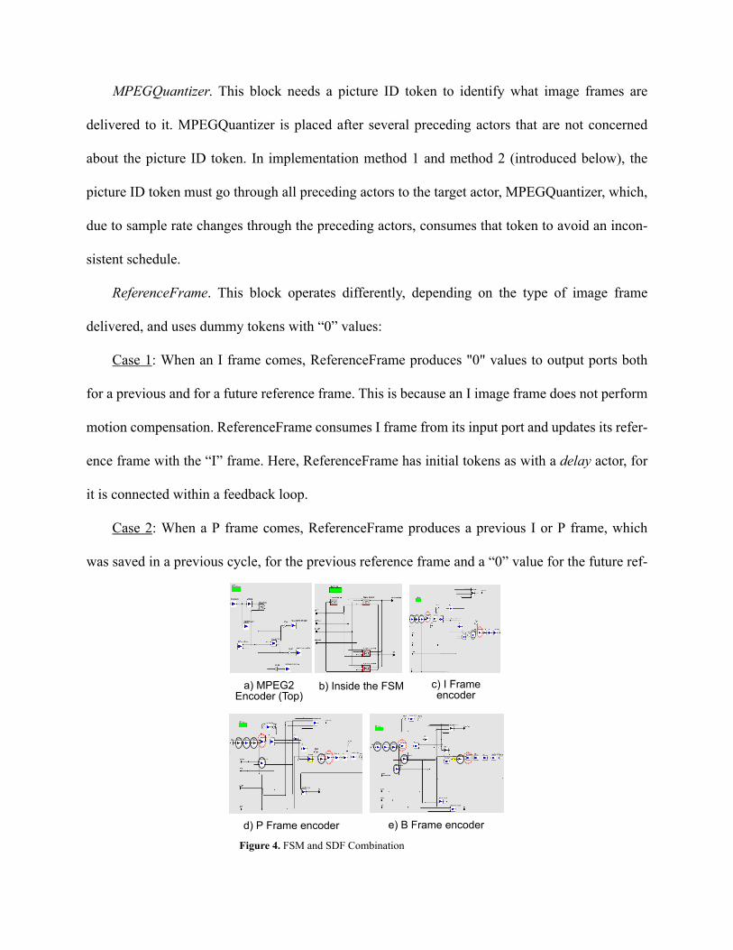
heterogeneous modeling capabilities of Ptolemy II. Figure 4 illustrates our resulting design.
Our FSM representation within the MPEG2 video encoder has three states where each state is
refined to three different SDF subgraphs, depending on the type of image frame: I, P or B. Since
an I frame is coded by exploiting only spatial redundancy, the SDF graph shown in figure 4(c) for
I frame processing does not have a motion compensator module. The SDF graph shown in figure
4(d) for P frame processing, which refers to only a previous I or P frame, has one motion compen-
sator module, while the SDF graph shown in figure 4(e) for B frame processing, which refers to
both a previous and a future I or P frame, has two motion compensator modules.
Here, it is useful to focus on two special functional blocks: MPEGQuantizer and Reference-
Frame, which help to distinguish our alternative encoder implementations.
MPEGQuantizer. This block needs a picture ID token to identify what image frames are
delivered to it. MPEGQuantizer is placed after several preceding actors that are not concerned
about the picture ID token. In implementation method 1 and method 2 (introduced below), the
picture ID token must go through all preceding actors to the target actor, MPEGQuantizer, which,
due to sample rate changes through the preceding actors, consumes that token to avoid an incon-
sistent schedule.
ReferenceFrame. This block operates differently, depending on the type of image frame
delivered, and uses dummy tokens with “0” values:
Case 1: When an I frame comes, ReferenceFrame produces "0" values to output ports both
for a previous and for a future reference frame. This is because an I image frame does not perform
motion compensation. ReferenceFrame consumes I frame from its input port and updates its refer-
ence frame with the “I” frame. Here, ReferenceFrame has initial tokens as with a delay actor, for
it is connected within a feedback loop.
Case 2: When a P frame comes, ReferenceFrame produces a previous I or P frame, which
was saved in a previous cycle, for the previous reference frame and a “0” value for the future ref-
Figure 4. FSM and SDF Combination
a) MPEG2 Encoder (Top)
b) Inside the FSM c) I Frame encoder
e) B Frame encoderd) P Frame encoder

erence frame. Like when an I frame ID comes, a P frame is also saved as a reference frame inside
of ReferenceFrame.
Case 3: When a B frame comes, ReferenceFrame produces two saved reference frames (P
and I frames) to the output ports. However, since a B frame is not used as a reference frame, it is
discarded and not used for updating reference frames inside of ReferenceFrame.
In summary, this implementation method (Method 1) can satisfy problem P1; however, P2,
P3 and P4 remain unsolved.
Method 2. SDF
In this method, we have implemented an MPEG2 Video encoder without integrating the FSM
model of computation. All functional blocks inside are same as the method 1. However, method 2
does not have separated I, P and B sub-encoders so that all image frames go through two motion
compensators with real values or dummy values depending upon the image frames. This imple-
mentation simplifies the design of an MPEG2 Video encoder. However, it still has the same prob-
lems (P2, P3 and P4) unsolved, as with method 1.
Method 3. BLDF
In this method, we separate the functional blocks of an MPEG2 video encoder into two parts: a
subinit and a body graph. The actors configuring the body subsystem are placed in the subinit
graph, and the actors actually processing image frames are placed in the body subsystem. First,
the subinit graph obtains information required for configuring a body subsystem from data tokens
delivered to itself and then converts image data tokens, themselves, into blocked parameters for
the body subsystem along with other parameters, such as block size and picture ID, obtained from
image data tokens.

In parameterized dataflow, blocked data tokens such as image frames directly go to a body
graph. An init or subinit graph manipulates only data tokens with parameter features for a body
subsystem. Therefore, an init or subinit graph cannot obtain parameters such as image resolution
or block size for manipulating iteration numbers of the actors in the associated “body” graph.
Early knowledge of the iteration count of each functional block for a body subsystem gives
more efficiency and flexibility in manipulating and predicting actors of the associated body graph.
Above all, an iteration count acts as a factor in a looped schedule of quasi-static scheduling in
BLDF. Thus, a more efficient quasi-static schedule of the associated body graph can be estab-
lished, while keeping much of the advantage (the predictability) of SDF in the schedule. The
name of BLDF originates from this feature that a block of data tokens is packaged as parameters
and then delivered to the associated body subsystem. Blocked data token delivery of BLDF
enables us to reduce dimensions of MDSDF [9] by processing multi dimensional data tokens
dimension by dimension with blocked data processing of nested BLDF subsystems. At the same
time, BLDF can be used in conjunction with MDSDF, with BLDF parameter control used to
define the boundaries of processing to be performed using MDSDF semantics.
Figure 5 shows iteration counts of the functional blocks in the associated body subsystem and
how iteration counts are used for factors in a looped quasi-static schedule of the MPEG2 video
encoder application. Here, the init subsystem contains the following three actors.
ImageFrameParameterizer. This actor delivers image frames to the ImagePropagator actor of
the body subsystem as BLDF parameter values.
MPEGHeaderGenreator. This actor generates a picture ID for the associated body sub-
system. The parameterized token delivery of a picture ID relieves the associated body graph of a
complicated meshed layout of an MPEG2 video encoder and the inconsistent scheduling problem
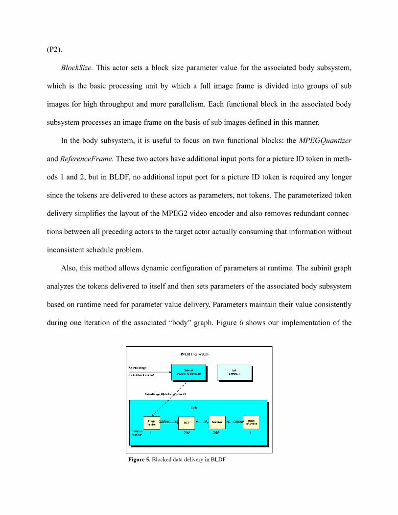
(P2).
BlockSize. This actor sets a block size parameter value for the associated body subsystem,
which is the basic processing unit by which a full image frame is divided into groups of sub
images for high throughput and more parallelism. Each functional block in the associated body
subsystem processes an image frame on the basis of sub images defined in this manner.
In the body subsystem, it is useful to focus on two functional blocks: the MPEGQuantizer
and ReferenceFrame. These two actors have additional input ports for a picture ID token in meth-
ods 1 and 2, but in BLDF, no additional input port for a picture ID token is required any longer
since the tokens are delivered to these actors as parameters, not tokens. The parameterized token
delivery simplifies the layout of the MPEG2 video encoder and also removes redundant connec-
tions between all preceding actors to the target actor actually consuming that information without
inconsistent schedule problem.
Also, this method allows dynamic configuration of parameters at runtime. The subinit graph
analyzes the tokens delivered to itself and then sets parameters of the associated body subsystem
based on runtime need for parameter value delivery. Parameters maintain their value consistently
during one iteration of the associated “body” graph. Figure 6 shows our implementation of the
Figure 5. Blocked data delivery in BLDF

MPEG2 video encoder application under BLDF.
4.2 Comparison
Method 1 (FSM + SDF Combination) has three different SDF graphs to which three states of the
FSM are refined. However, each refined SDF graph shares most of its actors with other refined
graphs, so there is a problem with redundant copies of actors among each refined SDF graph.
Method 2 (SDF) simplifies three sub-encoders within method 1 into one common encoder.
Thus, method 2 removes the problem of redundant (duplicated) actors. However, it still has prob-
lems of P2, P3 and P4 unsolved. Thus, unnecessary connections for picture ID delivery need to be
established through preceding actors, most of which don't need a picture ID, in order to avoid an
inconsistent schedule when the sample rate of tokens changes.
Method 3 (BLDF) has a similar layout as method 2, except that connections for delivering the
picture ID are removed due to parameterized token delivery. This makes the layout of the encoder
much simpler than method 2. Besides this, since parameters of the body subsystem are dynami-
cally set by the subinit graph, method 3 provides more flexibility and extensibility in the design
and maintenance of the application, especially by making room for future changes of the specifi-
b) “subinit” graph
c) “body” graphFigure 6. MPEG2 Encoder under BLDF
a) MPEG2 Encoder in BLDF (Top)

cation, along with improved efficiency in the design by reducing connections between functional
blocks.
To illustrate this efficiency advantage, the following table shows how many buffers and con-
nections in BLDF can be saved as the application complexity increases. In the MPEG2 applica-
tion, we have two actors named MPEGQuantizer and InverseMPEGquantizer that require
additional tokens for internal setting of values. The number of connections and the number of
buffers required can be calculated by multiplying the number of preceding actors and the number
of tokens for parameters.
Number of preceding actors: n
Number of tokens for parameters: m
Number of connections: n*m
Number of buffers required: n*m
Therefore, generally, n*m unnecessary connections and buffers between preceding actors can
be saved in BLDF, compared with alternative modeling formats.
5. CONCLUSIONS
This paper has developed a blocked dataflow (BLDF) modeling semantics for augmenting data-
flow-based DSP design tools with integrated capabilities for meta-modeling, block-based pro-
cessing, multidimensional representation, and dynamic parameter reconfiguration. BLDF builds
on parameterized dataflow semantics, and is compatible with decidable dataflow models such as
CSDF, MDSDF, SDF, and SSDF. This paper has described the semantics of BLDF, and illustrated

its efficiency through a case study of an MPEG 2 video encoder system. Useful directions for fur-
ther study include optimized synthesis, hardware/software partitioning algorithms, and automated
verification from BLDF specifications.
ACKNOWLEDGEMENTS
This research was supported by the Advanced Sensors Collaborative Technology Alliance,
DARPA (contract number MDA972-00-1-0023, through Brown University), and the National
Science Foundation (grant number 0325119).
REFERENCES
[1] B. Bhattacharya and S. S. Bhattacharyya. Parameterized dataflow modeling for DSP systems.
IEEE Transactions on Signal Processing, 49(10):2408-2421, October 2001.
Table 1. Comparison of three methods in "Buffer memory" and "Token delivery"
“ M P E G Q u a n tiz e r” a c to r < # o f p re c e d in g a c to rs > S D F + F S M : 3 ( I ) , 4 (P ) , 5 (B ) S D F , B L D F : 5 # o f to k e n s fo r p a ra m e te r s : 1
“ In v e r se M P E G Q u a n tiz e r” a c to r # o f p re c e d in g a c to r s : 1 # o f to k e n s fo r p a ra m e te rs : 1
T o ta l # B : N u m b e r o f b u ffe rs r e q u ir e d # W : N u m b e r o f w o rd s r e q u ir e d # W = # B * # W p B # W p B : N u m b e r o f w o rd s p e r b u f fe r c f) P ic tu re ID : 1 w o rd p e r b u ffe r is r e q u ir e d .(# W p B = 1 )
N u m b e r o f c o n n e c tio n s
N u m b e r o f b u f fe r s re q u ire d
N u m b e r o f c o n n e c tio n s
N u m b e r o f b u f fe rs r e q u ir e d
S D F + F S M
# B : = (3 + 4 + 5 )+ (1 + 1 + 1 ) = 1 5 b u f fe r s # W = # B * # W p B : = 1 5 * 1 = 1 5 w o r d s
I s u b e n c o d e r : = 3 * 1 = 3 P su b e n c o d e r : = 4 * 1 = 4 B su b e n c o d e r : = 5 * 1 = 5
I s u b e n c o d e r : = 3 * 1 = 3 P su b e n c o d e r : = 4 * 1 = 4 B su b e n c o d e r : = 5 * 1 = 5
I s u b e n c o d e r : = 1 * 1 = 1 P su b e n c o d e r : = 1 * 1 = 1 B su b e n c o d e r : = 1 * 1 = 1
I s u b e n c o d e r : = 1 * 1 = 1 P su b e n c o d e r : = 1 * 1 = 1 B su b e n c o d e r : = 1 * 1 = 1
S D F # B : = (5 )+ (1 ) = 6 b u f fe r s # W = # B * # W p B : = 6 * 1 = 6 w o r d s
5 * 1 = 5 5 * 1 = 5 1 * 1 = 1 1 * 1 = 1
B L D F # B : 0 b u f fe r s # W : 0 w o r d s
0 0 0 0
[2] S. S. Bhattacharyya, R. Leupers, and P. Marwedel. Software synthesis and code generation for
DSP. IEEE Transactions on Circuits and Systems — II: Analog and Digital Signal Processing,
47(9):849-875, September 2000.
[3] G. Bilsen, M. Engels, R. Lauwereins, and J. A. Peperstraete. Cyclo-static dataflow. IEEE
Transactions on Signal Processing, 44(2):397-408, February 1996.
[4] J. T. Buck. Static scheduling and code generation from dynamic dataflow graphs with integer-
valued control systems. In Proceedings of the IEEE Asilomar Conference on Signals, Systems,
and Computers, pages 508-513, October 1994.
[5] B. Kienhuis and E. F. Deprettere. Modeling stream-based applications using the SBF model of
computation. In Proceedings of the IEEE Workshop on Signal Processing Systems, pages 385-
394, September 2001.
[6] K. N. Lalgudi, M. C. Papaefthymiou, and M. Potkonjak. Optimizing computations for effec-
tive block-processing. ACM Transactions on Design Automation of Electronic Systems, 5(3):604-
630, July 2000.
[7] E. A. Lee. Overview of the Ptolemy project. Technical Report UCB/ERL M01/11, Department
of Electrical Engineering and Computer Sciences, University of California at Berkeley, March
2001.
[8] E. A. Lee and D. G. Messerschmitt. Static scheduling of synchronous dataflow programs for
digital signal processing. IEEE Transactions on Computers, February 1987.
[9] P. K. Murthy and E. A. Lee. Multidimensional synchronous dataflow. IEEE Transactions on
Signal Processing, 50(8):2064-2079, August 2002.
[10] C. Park, J. Chung and S. Ha, Efficient Dataflow Representation of MPEG-1 Audio (Layer
III) Decoder Algorithm with Controlled Global States, Proceedings of the IEEE Workshop on

Signal Processing Systems, Taiwan, ROC, Oct, 1999.
[11] S. Ritz, M. Pankert, and H. Meyr. Optimum vectorization of scalable synchronous dataflow
graphs. In Proceedings of the International Conference on Application Specific Array Processors,
October 1993.
[12] S. Ritz, M. Pankert, and H. Meyr. High level software synthesis for signal processing sys-
tems. In Proceedings of the International Conference on Application Specific Array Processors,
August 1992.