modeling of hydraulic fracture of concrete gravity dams by...
TRANSCRIPT

Research ArticleModeling of Hydraulic Fracture of Concrete Gravity Dams byStress-Seepage-Damage Coupling Model
Sha Sha12 and Guoxin Zhang2
1Department of Hydraulic Engineering Tsinghua University Beijing 100084 China2State Key Laboratory of Simulation and Regulation of Water Cycle in River Basin China Institute ofWater Resources and Hydropower Research Beijing 100038 China
Correspondence should be addressed to Guoxin Zhang gx-zhangiwhrcom
Received 28 November 2016 Revised 14 February 2017 Accepted 22 February 2017 Published 23 April 2017
Academic Editor Giovanni Garcea
Copyright copy 2017 Sha Sha and Guoxin Zhang This is an open access article distributed under the Creative Commons AttributionLicense which permits unrestricted use distribution and reproduction in any medium provided the original work is properlycited
High-pressure hydraulic fracture (HF) is an important part of the safety assessment of high concrete dams A stress-seepage-damagecoupling model based on the finite element method is presented and first applied in HF in concrete dams The coupling model hasthe following characteristics (1) the strain softening behavior of fracture process zone in concrete is considered (2) the mesh-dependent hardening technique is adopted so that the fracture energy dissipation is not affected by the finite element mesh size(3) four coupling processes during hydraulic fracture are considered By the damage model the crack propagation processes of a1 40 scaled model dam and Koyna dam are simulatedThe results are in agreement with experimental and other numerical resultsindicating that the damage model can effectively predict the carrying capacity and the crack trajectory of concrete gravity damsSubsequently the crack propagation processes of Koyna dam using three notches of different initial lengths are simulated by thedamage model and the coupling model And the influence of HF on the crack propagation path and carrying capacity is studiedThe results reveal that HF has a significant influence on the global response of the dam
1 Introduction
Hydraulic fracture is a phenomenon of crack propagationafter high-pressure water or other kinds of fluid enteringinto an existing crack Hydraulic fracture is an importantissue in the hydraulic engineering the petroleum engineer-ing mining and geotechnical industries In the hydraulicengineering mass concrete dams are likely to experiencecracking on their upstream downstream and base surfacesdue to the low tensile strength of concrete and the action ofinternal and external temperature changes shrinkage of theconcrete differential settlement of the foundation and otherfactors Concrete gravity dam is a type of concrete structurethat interacts with high-pressure water With time cracks arefilled with water and penetrate deep into the dam under theaction of high water pressure resulting in reduced carryingcapacity and safety of the dam Therefore for the safety ofhigh or ultrahigh concrete dams it is necessary to considerthe influence of hydraulic fracturing [1]
In hydraulic fracture of concrete and concrete gravitydams there are some studies on it Bruhwiler and Saouma[2 3] conducted hydraulic fracturing tests on concrete speci-mens of different gradations and examined thewater pressuredistribution in their cracks They found that the hydrostaticpressure in the cracks was a function of the crack openingdisplacement decreasing from the maximum pressure tozero along the fracture process zone Slowik and Saouma[4] investigated the pressure distribution inside a crack withrespect to time and the crack opening rate The effect ofsudden crack closure on the pressure distribution was alsoinvestigated Using the fluid mass and momentum conserva-tion theories Li et al [5] established a differential equation ofthe water pressure distribution in rock and concrete fracturescaused by hydraulic fracturing and derived a formula forcalculating the pressure at an arbitrary time during the crackpropagation process Bary et al [6] presented an approachusingmechanics of saturated porousmedia tomodel stronglycoupled hydromechanical effects in concrete Fang and Jin [7]
HindawiMathematical Problems in EngineeringVolume 2017 Article ID 8523213 15 pageshttpsdoiorg10115520178523213
2 Mathematical Problems in Engineering
studied the fracture process of concrete under the action ofwater pressure in fissure based on the extended finite elementmethod (XFEM) Barpi and Valente [8] simulated hydraulicfracturing of the dam-foundation joint and analyzed theeffect of fracture process zone on the path of crack formationDong and Ren [9] simulated the propagation of the crack atthe gravity dam heel under uniform pressure by the XFEMWang et al [10] studied hydraulic fracturing in concretegravity dam considering fluid-structure interaction by theXFEM and finite volume method
Hydraulic fracture is a complex problem involving fourcoupled processes (1) the deformation of the surroundingmedium induced by the water pressure on the fracturesurface (2) fluid flow within the fracture (3) propagationof the fracture (4) the leak-off of the fracturing fluid fromthe fracture into the surrounding medium [11] Howeveramong numerical studies of hydraulic fracturing in concretegravity dams mentioned above the fourth coupling processis not taken into account Further concrete is a quasibrittlematerial Fracture in concrete is characterized by the exis-tence of a nonlinear fracture process zone at the front of thereal crack tip Depending on how the fracture process zoneof the concrete is assessed crack analysis can be conductedusing linear elastic fracture mechanics (LEFM) or nonlinearfracture mechanics (NLFM) LEFM may produce inaccurateresults because of the neglect of the fracture process zonein the concrete Theoretically NLFM is more reasonablebeing based on the fictitious crackmodel with the applicationof the strain softening law of the fracture process zone[12] However among the numerical studies of hydraulicfracturing mentioned above LEFM is used mostly
There are many methods for the simulation of hydraulicfracture such as phase-field method [13] peridynamics [14]cellular automata method [15] discrete element method(DEM) [16] numerical manifold method (NMM) [17] ele-ment free method [18] finite element method (FEM) [19]and boundary element method (BEM) [20] For the excellentabilities in LEFM the boundary element method and espe-cially the displacement discontinuity method (DDM) havealso been extensively applied to hydraulic fracture modelingHigher order elements to DDM are introduced to improvethe precision due to singularity variations near the cracktip [21] In the DEM framework cracks propagate alongprescribed element boundaries when the stress intensityfactor meets the criteria and the crack opening is estimatedby a Coulomb friction model [22] FEM is the most matureand the most widely used FEM is a method based onthe continuum mechanics essentially It must be improvedto simulate the discontinuity The improving methods aredivided into two categories the variable mesh method andthe fixed mesh method In the variable mesh method themesh needs updating as the crack tip advances The crackedsurface must be consistent with the edge of the element anda fine mesh or singular element has to be adopted at thecrack tip which could be computationally expensive In thefixed mesh method the mesh keeps invariant and the crackis simulated by modifying the interpolation or constitutiverelation of the cracked element such as the XFEM thesmeared crackmodel and the continuumdamagemodelThe
use of the XFEM for hydraulic fracture problem can avoidremeshing However the XFEM also needs objective crackpropagation criteria which are usually based on quantitiessuch as crack-tip stresses and stress intensity factors So finecrack-tip meshes are necessary for accurate calculation ofthese quantities This means that fine meshes are needed ifcracks are unknown a priori leading to high computationalcost The smeared crack model describes a cracked solid byan equivalent anisotropic continuum with degraded materialproperties in the direction normal to the crack orientationand no remeshing is needed [23] In contrast the fixed meshmethod is more convenient
Among the numerical studies of hydraulic fracture inconcrete gravity dams mentioned above the XFEM isused mostly while the continuum damage model is lessused In this study by regarding concrete as a saturatedporous medium and employing the effective stress prin-ciple of porous media a stress-seepage-damage couplingmodel based on FEM is developed and first applied inhydraulic fracture in concrete gravity dams The couplingmodel has the following characteristics (1) the constitutivelaw considers the strain softening characteristic of fractureprocess zone damage-dependent pore-pressure-influencecoefficient stress-dependent permeability for the prepeakstage and deformation-dependent permeability for the post-peak stage (2) based on the principle of conservation offracture energy the damage model is combined with fracturemechanics to prevent the fracture energy dissipation frombeing affected by the finite element mesh size (3) fourcoupling processes during hydraulic fracture are consideredBy this coupling model hydraulic fracture of Koyna dam issimulated And the influences of hydraulic fracture on thecrack trajectory and the dam bearing capacity are discussed
2 Stress-Seepage-Damage Coupling Model
In this study the dam concrete is assumed to be a saturatedporous medium In practice dam concrete can hardly attaina saturated state owing to the small size of the pores andthe consequent very low permeability in the intact conditionExcept near cracks the pore pressure ofmost of the zones of aconcrete dam do not vary [24] The consideration of the damconcrete as a saturated porousmedium therefore constitutes asignificant simplification However the purpose of this studyis to investigate the impact of hydraulic fracture on the damIsotropic damage models are not appropriate for concretebecause the crack trajectory follows principal compressivestresses which are perpendicular to principal tensile stressespromoting crack initiation and propagation However ifanisotropic damage models are adopted both theoreticalderivation and numerical calculation are difficult In contrastisotropic damagemodels are easier to implementWhen con-sidering the effects of hydraulic fracturing water flows alongthe crack permeability coefficients in the directions parallelto the crack plane are different from that perpendicular to thecrack plane And the pore-pressure-influence coefficient inthe direction perpendicular to the crack plane is also differentfrom those parallel to the crack plane Thus in this study anisotropic damage model and an anisotropic seepage model
Mathematical Problems in Engineering 3
are used The following nonlinear behaviors are defined inthis study (1) the stress-strain relationship of the damagedelement (2) the variation of the pore-pressure-influencecoefficient caused by the damage and (3) the variation of thepermeability coefficients due to stress and the damage In thecalculations it is assumed that the compressive stress-strainrelationship is linear elastic because compressive stresseshigher than the compressive strength generally do not occurin a gravity dam The characteristics of the coupling modelare discussed below
21 Damage Model At the front of a real concrete cracktip there is a nonlinear fracture process zone where cohe-sive stresses can be transferred between the crack inter-faces through aggregate interlock and interface friction Theexistence of the fracture process zone causes the concreteto exhibit strain softening The mechanical properties ofthe fracture process zone can be well simulated using thecohesive crack model proposed by Hillerborg et al [12] Themajority of researchers have suggested the adoption of alinear stress-strain relationship for the ascending segmentunder uniaxial tension However different modes may occurin the descending segment including single-line descendingsegmented-line descending and curved descending [25]Irrespective of the adopted mode the fracture energy of thestress-strain curve should always remain the same In thisstudy the negative exponential equation developed by Jianget al [25] is adopted for the descending segment The stress-strain relationship under uniaxial tension can therefore beexpressed as
120590 = 1198640120576119905 120576119905 le 12057601198911199050119890minus120572(120576119905minus1205760) 120576119905 gt 1205760 (1)
where 1198640 is Youngrsquos modulus of the intact material 1198911199050 is thetensile strength 120576119905 is the uniaxial tensile strain 1205760 is the strainat cracking (= 11989111990501198640) and 120572 is the softening coefficient forcontrolling the descending segment
In Figure 1 the fracture energy 119866119865 is given by the areaenclosed by the stress-crack width curve and the coordinateaxes as expressed by (2) As shown in Figure 2 the fractureenergy per unit crack width 119892119891 is given by the area enclosedby the descending segment (represented by the line 120576 = 1205760)and the horizontal axis 120576 as expressed by (3)
119866119865 = int120590119889119908 119908 = intℎ119889120576 (2)
where 119908 is the sum of the opening displacements of themicrocracks in the fracture process zone and ℎ is the widthof the distribution area of the microcracks
119892119891 = intinfin1205760
120590119889120576119905 (3)
From (1)
119892119891 = intinfin1205760
120590119889120576119905 = intinfin1205760
1198911199050119890minus120572(120576119905minus1205760)119889120576119905 = 1198911199050120572 (4)
휎
GF
w
Figure 1 Stress versus crack width curve and fracture energy 119866119865휎
ft0
gf
휀0 휀
Figure 2 Fracture energy per unit crack width 119892119891
The relationship between the fracture energy 119866119865 and thefracture energy per unit crack width 119892119891 is as follows
119866119865 = 119892119891119897119905 (5)
where 119897119905 is a geometrical constant which is introduced as ameasure of the characteristic length of the element For aplane element 119897119905 is calculated as the square root of the relatedarea for each integration point In the case of a solid elementit is calculated as the cube root of the related volume for eachintegration point
It can be determined from (4) and (5) that the softeningcoefficient of the descending segment should satisfy
120572 = 1198911199050119897119905119866119865 (6)
According to the principle of equivalent strain proposedby Lemaitre [26] it can be assumed that the strain generatedby the Cauchy stress 120590 exerted on the damaged material isequal to the strain generated by the effective stress exertedon the undamaged material That is
120576 = 120590119864 =
1198640 = 120590(1 minus 119889) 1198640 (7)
The following is thus obtained
120590 = (1 minus 119889) 1198640120576 (8)
where 1198640 is Youngrsquos modulus of the undamaged material 119864is Youngrsquos modulus of the damaged material 119889 is the damage
4 Mathematical Problems in Engineering
Total stress 휎 Self-equilibrium stress bp
1
1 pp
휎y
휎x
byp
bxp
Effective stress 휎㰀 = 휎 minus bp
휎㰀x
휎㰀y
Figure 3 Decomposition of stresses in saturated porous media
variable with 119889 = 0 corresponding to the undamaged state d= 1 to the completely damaged state and 0 lt 119889 lt 1 to differentdegrees of damage
From the perspective of damage mechanics the nonlin-earity of the stress-strain relationships of rock and concreteis due to the formation and propagation of microcracks inthe materials through load-induced continuous damage Theconsequent brittleness is more obvious under tension It isthus appropriate to use an elastic damage constitutive modelto describe the mechanical properties It has been confirmedthat the results of an elastoplastic damage model do notsignificantly differ from those of an elastic damage model[27] The elastic damage constitutive model is thereforeadopted in this study
Based on (1) and (8) the equation of the damage evolutionunder uniaxial tension can be expressed as
119889 = 0 120576119905 le 12057601 minus 1205760120576119905 sdot 119890
minus120572(120576119905minus1205760) 120576119905 gt 1205760 (9)
22 Effective Stress Principle of Porous Media The concept ofthe effective stress as applied to rock and concrete saturatedby a single-phase fluid can be regarded as the developmentof Terzaghirsquos effective stress principle for soil Based onthe effective stress principle Biot first introduced a scalarparameter (known as Biot coefficient) to reflect the effect ofthe pore pressure on the effective stress [28ndash30] In [29] theporosity 119887119894 is defined as the ratio of the effective pore area tothe cross-sectional area 119860 119894 The effective pore area is definedas the sum of all the micropore areas per unit length in thedirection perpendicular to the cross-sectional area 119860 119894 Theporosity 119887119894 is also the ratio of the pore volume 119881119901 to the bulkvolume 119881119887 The elastic behavior of a porous dam concreteis generally assumed to be homogeneous and isotropic Anisotropic value of 119887119894 for which 119887119909 = 119887119910 = 119887119911 = 1198870 is oftenused where 1198870 is the initial Biot coefficient Fauchet et al [31]suggested 1198870 asymp 02 for the elastic analysis of an arch dam Forsoils 1198870 asymp 1 is assumed for stress calculations However forconcrete the parameter 1198870 is still lower than unity even in thestate of imminent failure [24]
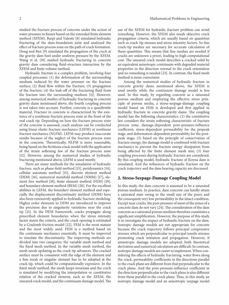
Tensile stresses are assigned a positive sign As shown inFigure 3 the total stress exerted on the element surface can bedivided into two parts the external stress bp in equilibriumwith the internal water pressure p and the effective stressTheaverage deformation of the element is related to the effectivestress which can be expressed as
1205901015840 = 119863 120576 1205901015840 = 120590 minus 119887 119901 (10)
where 1205901015840 is the effective stress vector (1205901015840 = 1205901015840119909 12059010158401199101205901015840119911 1205911015840119909119910 1205911015840119910119911 1205911015840119911119909119879) 119863 is the elasticity matrix 120576 = 120576119909 120576119910120576119911 120574119909119910 120574119910119911 120574119911119909119879 120590 is the total stress vector p is the porewater pressure 119887 is the pore-pressure-influence vectordefined as 119887 = 119887119909 119887119910 119887119911 0 0 0 in three-dimensionalanalysis
23 Relationship between Pore-Pressure-Influence Coefficientand Damage For the undamaged element 119887119909 = 119887119910 =119887119911 is assumed If the element is damaged the influencecoefficient perpendicular to the crack orientation would bedifferent from that parallel to the crack orientation Figure 4qualitatively illustrates the effects of the cracking on the pore-pressure-influence coefficients where 1 2 and 3 represent thedirections of the first second and third principal stressesrespectively A local coordinate system is generated with theprincipal stress directions as the axes 1198872 and 1198873may be withinthe same range namely 1198870 lt 1198872 = 1198873 lt 1198871 [32] 1198872 gt 1198870 isjustified because the diffusion of a crack in a finite area mayincrease the pore pressure action area paralleling to the crackdirection [33] Based on experimental observations Bary etal [6] proposed an anisotropic Biot tensor associated withthe damage degree and the pore pressure in each directionOwing to the lack of experimental data on the effects ofcracking on the pore-pressure-influence coefficients parallelto the crack direction it is assumed in this study that thecoefficients remain isotropic after the concrete is damagedimplying 1198871 = 1198872 = 1198873 In the elastic state 1198871 = 1198872 = 1198873 = 1198870where 1198870 is the initial Biot coefficient In the fully damaged
Mathematical Problems in Engineering 5
23
1
Crack planes
Evolution of pore-pressure-influence coefficients
Evolution of permeability
Figure 4 Effects of cracking on pore-pressure-influence coefficients and permeability
state 1198871 = 1198872 = 1198873 = 1 and the evolution of the pore-pressure-influence coefficient with the damage can be expressed as
1198871 = 1198872 = 1198873 = 1198870 + 119889 (1 minus 1198870) (11)
24 Relationship between Permeability Coefficients andStressDamage Concrete is composed of solid skeleton andmicroscopic pores This structural characteristic may causechanges in the microscopic geometry and pore structurewhen the material is loaded or disturbed resulting invariation of the porosity and permeability [34] Porositychange essentially comprises two parts (1) the change in porevolume caused by structural deformation and (2) changes ofthe pore structure and size due to the formation propagationand penetration of defects such as microcracks (ie the porestructure change caused by the material damage) [35] Manystudies have shown that the deterioration of concrete mostsignificantly affects its permeability coefficients Based ontests conducted on several groups of concrete samplesPicandet et al [36] developed a coupled equation of thepermeability coefficients of the material and its low-degreedamage Souley et al [37] and Gawin et al [38] also proposedequations of the permeability coefficients and damagevariable based on the results of experiments Chatzigeorgiouet al [39] used a discrete model to describe the couplingrelationship between the permeability coefficients and thedamage variable Pijaudier-Cabot et al [40] established therelationship between progressive damage (from diffusedto localized damage distribution) and the permeabilitycoefficients Further by introducing a seepage mutationcoefficient Zhao et al [41] and Zhang and Meng [42]developed seepage-stress coupled equations of concreteduring damage evolution under the action of complexstresses
When the element is in the elastic state (ie 119889 = 0)the permeability coefficients are exponentially related to theeffective stresses as follows [43]
11989611 = 11989601198901198860120590111989622 = 11989601198901198860120590211989633 = 119896011989011988601205903
(12)
where 1198960 is the initial permeability coefficient 1198860 is thecoupling coefficient 1205901 1205902 and 1205903 are the effective principalstresses which are positive when tensile and 11989611 11989622 and11989633 are the principal permeability coefficients in directionsrespectively corresponding to the principal stresses
When the first principal stress reaches the tensilestrength the element is damaged (ie 119889 gt 0) and a fractureis generated in it Figure 4 qualitatively demonstrates theeffect of cracking on the permeability of the element Thewater in the concrete mainly flows along the fracture withthe permeability coefficients increasing in directions 2 and 3Assuming that the fracture is planar and has parallel sides theaperture of the fracture is given approximately by
119906 = (1205761 minus 120576119905) 119897119905 (13)
where 120576119905 and 119897119905 are as defined in Section 21 The so-calledcubic law gives the flow rate between smooth parallel platesas
119902 = 119892119906312120592
Δ119867119897 (14)
where Δ119867 is the water head loss across the two ends 120592is the kinematic viscosity coefficient of water and 119892 is theacceleration of gravity In (14) the hydraulic conductivityis given by the term 119892119906212120592 Therefore the hydraulicconductivity for a damaged element can be expressed as
11989611 = 119896011989011988601205901
11989622 = 11989633 = 119892119906212120592 = 119892 [(1205761 minus 120576119905) 119897119905]212120592
(15)
The permeability matrix [1198961015840] in the local coordinatesystem contains 11989611 11989622 and 11989633 By transforming this matrixinto the global coordinate system through coordinate con-versation the permeability matrix in the global coordinatesystem [119896] can be expressed as
[119896] = [120573]119879 [1198961015840] [120573] (16)
where [119896] = [ 119896119909119909 119896119909119910 119896119909119911119896119910119909 119896119910119910 119896119910119911119896119911119909 119896119911119910 119896119911119911
] [1198961015840] = [ 11989611 0 00 11989622 00 0 11989633
] and [120573] =[ 1198971 1198981 11989911198972 1198982 11989921198973 1198983 1198993
] [120573] is the transformation matrix between the
two coordinate systems and 119897119894 119898119894 119899119894 (119894 = 1 2 3) are therespective direction cosines of the principal stress 12059011989425 Basic Differential Equations of Seepage Field Assumingthat the water is incompressible according to Darcyrsquos lawthe calculation of the steady seepage field with free surface(without internal sources) can be reduced to solving the
6 Mathematical Problems in Engineering
quasiharmonic equations that satisfy the boundary condi-tions
120597120597119909119894 [119896119894119895
120597119867120597119909119895] = 0119867|Γ1 = 120601 (119909 119910 119911)
119896120597119867120597120578
10038161003816100381610038161003816100381610038161003816Γ2 = 119902 (119909 119910 119911)119867|Γ3 = 119885 (119909 119910)
119896120597119867120597120578
10038161003816100381610038161003816100381610038161003816Γ3 = 0
119867|Γ4 = 119885 (119909 119910) 119896120597119867
12059712057810038161003816100381610038161003816100381610038161003816Γ4 le 0
(17)
where119867 is the water head 119896119894119895 is the permeability tensor andD1 D2 D3 and D4 respectively denote the boundaries of thewater head flow free surface and overflow
3 Realization of Finite Element Method
In this study the cracking problem is formulated in effectivestresses namely total stresses minus the pore pressures Andthe effective stresses are used to perform the computationIn the finite element analysis the equilibrium between theexternal load and the internal load is as follows
∭Ω[119861]119879 1205901015840 119889119881 = 119865 minus 119865119901 (18)
where [119861] is the stress-displacement transformation matrix1205901015840 is the effective stress vector and 119865 and 119865119901 are theexternal load and internal pore pressure load respectively
119865119901 = ∭Ω[119861]119879 119887 119901 119889119881 (19)
The seepage stress and damage fields mutually affect andare coupled to each other and solving the problem using thefully coupled equations would require a significant amount ofcalculation The weak coupled method is used to solve eachequation independently In the solution of the seepage fieldof the Nth load step the permeability coefficients modifiedby the stress field and the damage field of the (119873 minus 1)th loadstep are used to form the new permeability stiffness matrixand the seepage field of the Nth load step is obtained Thedisplacement field stress field and damage field of the Nthload step are then obtained Figure 5 shows the flowchart ofthe stress-seepage-damage coupling program
During the calculation the loads are applied by theincremental method and the load increment is set to be quitesmall The total quantity method is used for the iteration ineach load stepThe damage degree could increase or decreaseduring an iteration process but could not reduce below thatcorresponding to the last load step It is therefore necessaryto preserve the damage degree of the last load step The loadof a current iteration step is the sum of the load incrementof the current load step and the equivalent load incrementof the unbalanced stress caused by the damage in the lastiteration step Further the equivalent load increment of theunbalanced stress is the load increment due to the differencebetween the computational stress and the bearing stress Itshould be noted that the load of the first iteration step is thesum of the external load increment of the current load stepand the residual unbalanced force of the last load step Theequivalent load increment of the unbalanced stress and theresidual unbalanced force can be calculated using (20) and(21) respectively
Δ119891119894119894step = ∭Ω[119861]119879 (120590119894stepminus1 minus 120590119894119894step) 119889119881 (119894 step ge 1 119894 ge 1) (20)
Δ119891119894step = Δ119891119895119894step minus Δ119891119895minus1119894step assuming that the calculation is convergent in the jth iteration step (21)
where Δ119891119894119894step is the equivalent load increment of the 119894thiteration step of the (i step)th load step required to be addedto the load increment of the (119894 + 1)th iteration step if thecalculation remained divergent in the 119894th iteration step andΔ119891119894step is the residual unbalanced force of the (i step)th loadstep required to be added to the load increment of the firstiteration step of the (i step + 1)th load step that is
Δ1198910119894step = Δ119891119894stepminus1 (119894 step ge 1) (22)
When the iteration converges the residual unbalanced forceis generally very small
The permeability stiffness matrix [119870119904]119894step of each loadstep is derived from the permeability coefficients modifiedin accordance with the stress and damage states of the lastload step When i step = 1 [119870119904]1 is derived from the initialpermeability coefficients The stiffness matrix of the firstiteration step [119870]1119894step of each load step is derived from theelasticity coefficient modified based on the damage state ofthe last load step When i step = 1 [119870]11 is derived from theinitial elasticity coefficient The stiffness matrix of the otheriteration steps [119870]119894119894step (119894 gt 1) in each load step is obtainedfrom the elasticity coefficients modified in accordance withthe damage state of the (119894 minus 1)th iteration step
Mathematical Problems in Engineering 7
Inputting andprocessing the data
Starting the stress-seepage-damagecoupling program
Load step istep = 1 nstep
Loading the seepage boundaryconditions
Judging the damage state No
Yes
istep = nstep
Outputting data andending
Starting the damage iteration i = 0
Seepagemodule
Modifying the permeability coefficients and thepore-pressure-influence coefficients of the Gauss points
Damageiterationmodule
Couplingmodule
Yes
NoModifying elasticity coefficients of the Gauss points
Initializing훿0 = 0 휀0 = 0
휎0 = 0 Δf0 = 0
Integrating [Ks]istep fsistep
Solving the equation [Ks]istep Histep = fsistep
Integrating istep ΔFpistep
ΔFistepIntegrating
i = i + 1 integrating [K]iistep
Solving the equation [K]iistep Δ훿iistep = ΔFistep + ΔFpistep + Δfiminus1istep
Getting Δ휀iistep 휀iistep
storing diistep and integrating Δfiistep
diistep minus diminus1istep lt TOL
Modifying elasticity coefficients of the Gauss pointsStoring 훿istep 휀istep 휎istep and integrating Δfistep
儩儩儩儩儩儩儩儩
Fp
Figure 5 Flowchart of coupling program
Let us assume that I is the seepage module II is thedamage iteration module and III is the coupling moduleIn this study the computations are performed in a weaklycoupled form in a sequential manner by applying I-II-IIIwithout iteration However there are iterations in the damageiterationmodule To guarantee the convergence of the resultsa small load step should be applied The smaller the load stepis the more accurate the results are When the load step issmall enough the results of the weakly coupled algorithmcan be regarded as those of the strongly coupled algorithm(applying I-II-III with iteration)
The coupling program can also be used to investigatethe crack propagation without consideration of the stress-seepage-damage coupling effect By inputting the controlparameters the seepage and coupling modules can beskipped and the damage iterationmodule directly calculated
4 Case Study
41 Crack Propagation Analysis of Model Gravity DamCarpinteri et al [44] once conducted fracture tests on a 1 40scaled gravity dam subjected to equivalent hydraulic loads in
8 Mathematical Problems in Engineering
2000
248 1680
600
F
800
2856
5942
5866
5328
55∘
(a)
250150
24002800
600
45∘
(b)
150
300
150F
(c)
Figure 6 Dimensions and load distribution of gravity dam models (unit mm)
the structural and material laboratory of University of Turinin Italy The model was cast with conventional concrete mixand was 24m high 20m wide at the bottom and 03mthick A notch of length 02W (30 cm) was fabricated onits upstream face at a quarter of its height where 119882 is thedam thickness at the location of the notch The dimensionsof the models are shown in Figure 6 The applied force wasdistributed as four concentrated loads with intensities asshown in Figure 6(a)The force was gradually increased untilfailure of the dam The mechanical properties of the utilizedconcrete are listed in Table 1
Various researchers have performed numerical simula-tions of the above tests using differentmodels and approachessuch as a combination of FEM and the cohesive crack modelof Barpi and Valente [45] the XFEM of Du et al [46] Inthe present study the experimental model is analyzed by thedamage model and the predicted responses are comparedwith the experimental results and the results of Barpi andValente [45] and Du et al [46]
Figure 7 shows the relationship between the total appliedforce and the CMOD as obtained by the present damagemodel the cohesive crack model of Barpi and Valente [45]and the XFEM of Du et al [46] and the experimental resultsAs can be seen from Figure 7 the peak load predicted bythe present damage model is in good agreement with thosedetermined by the experiment and Barpi and Valente [45]that predicted by the XFEM is relatively low It can alsobe seen from the figure that the predictions of the presentdamage model indicate an initial stiffness which agrees well
0
100
200
300
400
500
600
700
800
00 01 02 03 04 05 06
Load
(kN
)
CMOD (mm)
Damage modelBarpi and Valente (2000)
ExperimentDu et al (2005)
Figure 7 Load versus CMOD
with the experimental resultsThe results of Barpi andValente[45] and Du et al [46] indicated a softer prepeak responseand larger CMOD at the peak loadThere is a little differencebetween the postpeak response of this study and that of theexperiment
Figure 8 shows the damage distribution determinedin the present study Figure 9 compares the numericallyand experimentally determined crack propagation pathsThe experimentally observed crack trajectory is initiallyhorizontal and then turns toward the dam toe The crack
Mathematical Problems in Engineering 9
Table 1 Material parameters of gravity dam models
Youngrsquos modulus 119864(GPa) Poissonrsquos ratio ] Density 120588
(kgm3)Tensile strength119891119905 (MPa)
Fracture energy 119866119891(Nm)
357 01 2400 36 184
Table 2 Mechanical properties of Koyna dam concrete
Youngrsquos modulus E(GPa) Poissonrsquos ratio ] Density 120588
(kgm3)Tensile strength 119891119905
(MPa)Fracture energy 119866119891
(Nm)25 02 2450 10 100
Damage1
088889
077778
066667
055556
044444
033333
022222
011111
0
Figure 8 Damage distribution
The experimentThis study
Du et alBarpi and Valente
Figure 9 Comparison of crack propagation paths
trajectories obtained by Barpi and Valente [45] and Du et al[46] are initially downward and then begin to propagate witha nearly constant slope representing significant deviationfrom the experimentally observed crack profile The damagedistribution determined in this study also agrees well with theexperimentally observed trajectory further substantiatingthe validity of the damage model for predicting the cracktrajectory The discrete crack model and XFEM thus do notappear to be significantly better than the present damagemodel for predicting crack trajectory in a case study
42 Crack Propagation Analysis of Practical Gravity Dam(Koyna Dam) In this section the crack propagation pro-cesses of Koyna dam under overflow are simulated by thedamage model and the coupling model respectively Koyna
gravity dam was severely damaged near the dam neck by astrong earthquake [47] and has become a typical referencepoint for static and dynamic loading of a dam over the lastfew decades Gioia et al [48] used linear elastic fracturemechanics to investigate the fracture response of a damwith a preset notch on its upstream face and subjected tooverflow while Bhattacharjee and Leger [49] employed asmeared crack model for the same purpose The nonlinearresponse of Koyna dam under overflow is investigated inthe present study To facilitate comparison of the resultswith those of previous studies the employed geometry andconfiguration are the same as those used by Bhattacharjee andLeger [49] The employed geometry and finite element meshare shown in Figure 10 A prefabricated horizontal notch isset on the upstream face at the elevation of the downstreamslope variationThe initial depth of the notch is here denotedby a and the dam thickness at the location of the initial notchby 119897 (119897 = 193mm) A plane stress state is assumed in thestudy The considered loads include the self-weight of thedam hydrostatic pressure of the full dam and increment ofthe water pressure due to reservoir overflow The bottom ofthe dam is rigidly supported Table 2 gives the mechanicalproperties of the dam concrete
421 Crack Propagation Analysis withoutConsideration of Coupling Effect
(1) Initial Notch Length 119886 = 01119897 The relationships betweenthe overflow and the horizontal displacement of the dam crestdetermined by the present damage model the smeared crackmodel of Bhattacharjee and Leger [49] and Gioia et al [48]using LEFM are shown in Figure 11 The initial displacementof the dam crest corresponds to the combined load of the self-weight and the full reservoir pressure without overflowThereis consistency among the displacements obtained by the threemethods before the obvious occurrence of nonlinearity Inthe nonlinear stage the results of the present study agreewell with those of Bhattacharjee and Leger [49] The ultimateoverflows determined by Bhattacharjee and Leger [49] inthe present study and by Gioia et al [48] are approximately100 102 and 140m respectively The structural resistancespredicted by the smeared crackmodel and the damagemodelappear to be slightly lower than those determined by LEFManalysis
The presently determined damage distribution for anoverflow of 102m is shown in Figure 12 The distribution
10 Mathematical Problems in Engineering
148
700
365
1030193
The initial crack
Figure 10 Geometry and finite element mesh of Koyna dam (unit mm)
0
2
4
6
8
10
12
14
16
0 10 20 30 40 50 60 70 80
Ove
rflow
(m)
Crest displacement (mm)
Gioia et alBhattacharjee and Leacuteger (1994)
The damage model
Figure 11 Overflow versus horizontal displacement of dam crest
Damage1
088889
077778
066667
055556
044444
033333
022222
011111
0
Figure 12 Damage distribution (overflow = 102m)
is compared with the results of Gioia et al [48] and Bhat-tacharjee and Leger [49] in Figure 13 According to thepresent numerical simulation the crack initially propagateshorizontally With increasing overflow the crack graduallyturns downward due to the increase in compressive stress
downstreamof the damThe crack propagation path obtainedby Gioia et al [48] actually corresponds to an overflowof about 14m which explains its longer path in Figure 13Nevertheless its consistency with that of the present studyis apparent Both paths initially run horizontally over a veryshort distance and then turn downward The crack growthpath obtained by Bhattacharjee and Leger [49] correspondsto an overflow of about 100m It initially runs nearlyhorizontally before turning downward when the crack lengthreaches half the width of the dam neck The damage zone isin good agreement with the results of Gioia et al [48]
(2) Different Initial Notch Lengths To examine the effect ofthe initial notch length 119886 on the carrying capacity and crackpath three initial lengths are respectively used for analysisnamely 119886 = 01119897 02119897 and 03119897 The relationships betweenthe overflow and the horizontal displacement of the dam crestfor the three cases are shown in Figure 14The correspondingdamage distributions for an overflow of 102m are shown inFigure 15
It can be seen from Figure 10 that (1) the critical overflowat which the dam is transformed from the linear state intothe nonlinear state differs with the length of the initial notchbeing 86 74 and 70m for a = 01l 02l and 03l respectivelyand (2) the ultimate overflows for the various values of a areextremely close being about 102m It can also be seen fromFigure 15 that the cracks initially extend in the horizontaldirection and then turn downward at nearly the same pointand with almost the same deflection angle The crack pathsare also almost the same The length of the initial notchthus only affects the critical overflow for transformation intothe nonlinear state The shorter the length the higher thecritical overflow The notch length has no obvious effect onthe ultimate carrying capacity of the dam and the crack path
422 Crack Propagation considering Coupling Effect Toinvestigate the impact of the coupling effect during crackgrowth on the crack propagation path and carrying capac-ity of the dam nonlinear stress-seepage-damage coupling
Mathematical Problems in Engineering 11
This study
Bhattacharjee and Leacuteger
Gioia et al
Figure 13 Comparison of crack trajectories obtained by differentmethods
0
2
4
6
8
10
12
0 10 20 30 40 50 60 70 80
Ove
rflow
(m)
Crest displacement (mm)
a = 01 l
a = 02 l
a = 03 l
Figure 14 Overflow versus horizontal displacement of dam crest
analyses are conducted on the dam using the three initialnotch lengths in Section 421(2) The initial permeabilitycoefficient 1198960 is set as 5times 10minus9ms and the coupling coefficienta0 is set as 001 It is really true that the dam which is 100mhigh is constructed in reality with drains Due to lack ofinformation about the drains of Koyna dam the drains arenot taken into account in this study
In this section in order to select an appropriate loadstep five different load steps are chosen 10m 05m 01m005m and 001m respectively Taking Koyna dam with aninitial notch a = 01l as an example the ultimate overflowsunder the five load steps are 80m 75m 72m 70m and698m respectively Assuming the result of the load step001m as the precise solution the errors of the load steps10m 05m 01m and 005m are 1461 745 315 and029 respectively It can be seen that when the load step istaken as 005m the value of the load step has little influenceon the solution Thus the result of the load step 005m is
convergent and the load step 005m can be chosen in thecalculation of this section
(1) Initial Notch Length 119886 = 01119897 The relationships betweenthe overflow and the horizontal displacement for an initialnotch length a of 01l with and without consideration ofthe coupling effect are shown in Figure 16 The damagedistribution with consideration of the coupling effect isshown in Figure 17 It can be seen from Figure 16 that beforethe occurrence of obvious nonlinearity the results for the twocases are in agreement When the coupling effect is takeninto consideration the critical overflow that transforms thedam from the linear state into the nonlinear state is 41mand the ultimate overflow is 70mThis represents significantdecreases in both parameters compared to when not consid-ering the effect Further from a comparison of Figures 15(a)and 17 it can be seen that consideration of the coupling effectdecreases the horizontal crack propagation distance whileincreasing the deflection angle of the downward turn and thetotal length of the path
(2) Different Initial Notch Lengths Figure 18 shows thedamage distributions for the three initial notch lengthscorresponding to an overflow of 42m with consideration ofthe coupling effect The relationships between the overflowand the horizontal displacement of the dam crest for the threenotch lengths are shown in Figure 19The critical and ultimateoverflows with and without consideration of the couplingeffect are given in Table 3
It can be seen fromFigure 18 that for a given overflow thecrack only propagates over a short distance in the horizontaldirection when a = 01l while it initially propagates in thehorizontal direction and then turns downward when a = 02lWhen a = 03l the crack turns downward almost directly andthe propagation distance is nearly twice that for a = 02l Withconsideration of the coupling effect the crack propagationdistance increases with increasing initial notch length It canalso be seen from Figure 19 that with consideration of thecoupling effect the critical and ultimate overflows decreasewith increasing initial notch length Further Table 3 indicatesthat with consideration of the coupling effect the rates ofreduction of the critical and ultimate overflows increase withincreasing initial notch length
5 Conclusions
In this study a stress-seepage-damage coupling model basedon FEM is developed and first applied in hydraulic frac-ture of concrete gravity dams The coupling model has thefollowing characteristics (1) The constitutive law of thiscoupling model considers the strain softening characteristicof fracture process zone damage-dependent pore-pressure-influence coefficient stress-dependent permeability for theprepeak stage and deformation-dependent permeability forthe postpeak stage (2) the mesh-dependent hardening tech-nique is adopted so that the fracture energy dissipation is notaffected by the finite element mesh size (3) four couplingprocesses during hydraulic fracture are considered (a) thedeformation of the surrounding medium induced by the
12 Mathematical Problems in Engineering
Damage1
088889
077778
066667
055556
044444
033333
022222
011111
0
(a)
Damage1
088889
077778
066667
055556
044444
033333
022222
011111
0
(b)
Damage1
088889
077778
066667
055556
044444
033333
022222
011111
0
(c)
Figure 15 Damage distributions for overflow of 102m (a) a = 01l (b) a = 02l and (c) a = 03l
Table 3 Comparison of dam carrying capacities with and without consideration of coupling effect
Initial crack length
Without consideration ofcoupling effect
With consideration of couplingeffect Percentage change
Critical load (m) Carryingcapacity (m) Critical load (m) Carrying
capacity (m) Critical load Carryingcapacity
01l 60 102 41 70 minus317 minus31402l 50 102 20 53 minus600 minus48003l 30 102 10 42 minus667 minus588
0
2
4
6
8
10
12
0 10 20 30 40 50 60 70
Ove
rflow
(m)
Crest displacement (mm)
Uncoupling modelCoupling model
Figure 16 Overflow versus horizontal displacement of dam crest
water pressure on the fracture surface (b) fluid flow withinthe fracture (c) propagation of the fracture (d) the leak-offof the fracturing fluid from the fracture into the surroundingmedium
The damage model is first used to simulate crack prop-agation of a 1 40 scaled model dam The crack trajectoryand structural response agreed well with the experimentalresults Then the damage model is used to simulate crackpropagation of Koyna dam with an initial notch on theupstream face under overflow The numerically determinedcrack trajectory and structural response of Koyna dam agreewell with the previously reported numerical results These
Damage1
088889
077778
066667
055556
044444
033333
022222
011111
0
Figure 17 Damage distribution for overflow of 70m
results validate the present damage model for predicting thecarrying capacity and crack trajectory in concrete gravitydams
Subsequently the crack propagation processes of Koynadam using three notches of different initial lengths aresimulated by the damage model and the coupling model Bycomparing the results obtained by the twomodels it is foundthat hydraulic fracture produces the following influences (1)decrease in the horizontal propagation distance of the crackpath increases in the deflection angle when the crack turnsdownward and the total propagation distance (2) significantdecreases in the critical load and ultimate carrying capacity ofthe dam (3) increase in the crack propagation distance at thesame load with increasing initial notch length (4) increases
Mathematical Problems in Engineering 13
Damage1
088889
077778
066667
055556
044444
033333
022222
011111
0
(a)
Damage1
088889
077778
066667
055556
044444
033333
022222
011111
0
(b)
Damage1
088889
077778
066667
055556
044444
033333
022222
011111
0
(c)
Figure 18 Damage distributions for overflow of 42m (a) a = 01l (b) a = 02l and (c) a = 03l
012345678
0 10 20 30 40 50 60 70
Ove
rflow
(m)
Crest displacement (mm)
a = 01 l
a = 02 la = 03 l
Figure 19 Overflow versus horizontal displacement of dam crest
in the rates of decrease of the critical and ultimate loadswith increasing initial notch length This demonstrates thathydraulic fracture significantly affects the crack growth pathpropagation distance and ultimate carrying capacity of thedam
Hydraulic fracture is a complex problem and the effectsof damage on pore-pressure-influence coefficients and per-meability coefficients need to be further studied
Conflicts of Interest
The authors declare that there are no conflicts of interestregarding the publication of this paper
Acknowledgments
The research is supported by the National Key Research andDevelopment Project of China (Grant no 2016YFB0201000)the National Key Basic Research Program of China (Grantnos 2013CB036406 2013CB035904) the National Natu-ral Science Foundation of China (Grant nos 5157925251439005) the Special Scientific Research Project of the StateKey Laboratory of Simulation and Regulation of Water Cycle
in River Basin and the Special Scientific Research Projectof the China Institute of Water Resources and HydropowerResearch
References
[1] J-S Jia X-Y Li and C-Y Zheng ldquoStudies on safety problemof high gravity dams higher than 200 m with consideration ofhydraulic fracturing under water pressurerdquo Journal of HydraulicEngineering vol 37 no 12 pp 1509ndash1515 2006
[2] E Bruhwiler and V E Saouma ldquoWater fracture interaction inconcretemdashpart I fracture propertiesrdquo ACI Materials Journalvol 92 no 3 pp 296ndash303 1995
[3] E Bruhwiler and V E Saouma ldquoWater fracture interaction inconcretemdashpart II hydrostatic pressure in cracksrdquoACIMaterialsJournal vol 92 no 4 pp 383ndash390 1995
[4] V Slowik and V E Saouma ldquoWater pressure in propagatingconcrete cracksrdquo Journal of Structural Engineering vol 126 no2 pp 235ndash242 2000
[5] Z-L Li Q-W Ren and Y-H Wang ldquoFormula for waterpressure distribution in rock or concrete fractures formed byhydraulic fracturingrdquo Journal of Hydraulic Engineering vol 36no 6 pp 656ndash661 2005
[6] B Bary J-P Bournazel and E Bourdarot ldquoPoro-damageapproach applied to hydro-fracture analysis of concreterdquo Jour-nal of Engineering Mechanics vol 126 no 9 pp 937ndash943 2000
[7] X-J Fang and F Jin ldquoCoupling model for interaction betweenfissure water and cracking in concreterdquo Journal of HydraulicEngineering vol 38 no 12 pp 1466ndash1474 2007
[8] F Barpi and S Valente ldquoModeling water penetration at dam-foundation jointrdquo Engineering Fracture Mechanics vol 75 no3-4 pp 629ndash642 2008
[9] Y-WDong andQ-W Ren ldquoAn extended finite elementmethodfor modeling hydraulic fracturing in gravity damrdquo Journal ofHydraulic Engineering vol 42 no 11 pp 1361ndash1367 2011
[10] K F Wang Q Zhang and X Z Xia ldquoModelling of hydraulicfracturing for concrete gravity dams under fluid-structureinteractionrdquo Applied Mathematics and Mechanics vol 36 no 9pp 970ndash980 2015
[11] T Mohammadnejad and A R Khoei ldquoAn extended finite ele-ment method for hydraulic fracture propagation in deformableporous media with the cohesive crack modelrdquo Finite Elementsin Analysis and Design vol 73 no 15 pp 77ndash95 2013
14 Mathematical Problems in Engineering
[12] A Hillerborg M Modeer and P-E Petersson ldquoAnalysis ofcrack formation and crack growth in concrete by means offracture mechanics and finite elementsrdquo Cement and ConcreteResearch vol 6 no 6 pp 773ndash781 1976
[13] AMikelicM FWheeler andTWick ldquoPhase-fieldmodeling ofa fluid-driven fracture in a poroelasticmediumrdquoComputationalGeosciences vol 19 no 6 pp 1171ndash1195 2015
[14] H Ouchi A Katiyar J York J T Foster and M M SharmaldquoA fully coupled porous flow and geomechanics model forfluid driven cracks a peridynamics approachrdquo ComputationalMechanics vol 55 no 3 pp 561ndash576 2015
[15] P-Z Pan J Rutqvist X-T Feng F Yan and Q Jiang ldquoAdiscontinuous cellular automaton method for modeling rockfracture propagation and coalescence under fluid pressurizationwithout remeshingrdquo Rock Mechanics and Rock Engineering vol47 no 6 pp 2183ndash2198 2014
[16] H Shimizu S Murata and T Ishida ldquoThe distinct elementanalysis for hydraulic fracturing in hard rock considering fluidviscosity and particle size distributionrdquo International Journal ofRock Mechanics and Mining Sciences vol 48 no 5 pp 712ndash7272011
[17] G Zhang X Li andH Li ldquoSimulation of hydraulic fracture uti-lizing numericalmanifoldmethodrdquo Science China TechnologicalSciences vol 58 no 9 pp 1542ndash1557 2015
[18] MN Oliaei A Pak andK Soga ldquoA coupled hydro-mechanicalanalysis for prediction of hydraulic fracture propagation in sat-urated porous media using EFGmesh-less methodrdquo Computersand Geotechnics vol 55 pp 254ndash266 2014
[19] S Secchi and B A Schrefler ldquoA method for 3-D hydraulicfracturing simulationrdquo International Journal of Fracture vol178 no 1-2 pp 245ndash258 2012
[20] B Ganis M E Mear A Sakhaee-Pour M F Wheeler and TWick ldquoModeling fluid injection in fractures with a reservoirsimulator coupled to a boundary element methodrdquo Computa-tional Geosciences vol 18 no 5 pp 613ndash624 2014
[21] A Abdollahipour M Fatehi Marji A Yarahmadi Bafghiand J Gholamnejad ldquoSimulating the propagation of hydraulicfractures from a circular wellbore using the displacementdiscontinuity methodrdquo International Journal of Rock Mechanicsand Mining Sciences vol 80 pp 281ndash291 2015
[22] K Yoshioka and B Bourdin ldquoA variational hydraulic fracturingmodel coupled to a reservoir simulatorrdquo International Journal ofRock Mechanics and Mining Sciences vol 88 pp 137ndash150 2016
[23] Y J Hu G L Chen W P Cheng and Z J Yang ldquoSimulation ofhydraulic fracturing in rockmass using a smeared crackmodelrdquoComputers and Structures vol 137 no 6 pp 72ndash77 2014
[24] Z P Bazant ldquoPore pressure uplift and failure analysis ofconcrete damsrdquo in Proceedings of the International Symposiumon Criteria and Assumptions for Numerical Analysis of Dams DJ Naylor K G Stagg and O C Zienkiewicz Eds pp 782ndash803Swansea UK 1975
[25] J J Jiang X Z Lu and L P Ye Finite Element Analysis ofConcrete Structures Tsinghua University Press Beijing China2005
[26] J Lemaitre ldquoHow to use damage mechanicsrdquoNuclear Engineer-ing and Design vol 80 no 2 pp 233ndash245 1984
[27] Q-W Ren S Liu J-P Chen and C-L Zhou ldquoNumericalresearch on the progressive failure of gravity dam foundationrock mass based on damage theoryrdquo Journal of HydraulicEngineering vol 45 no 1 pp 1ndash9 2014
[28] M A Biot ldquoGeneral theory of three-dimensional consolida-tionrdquo Journal of Applied Physics vol 12 no 2 pp 155ndash164 1941
[29] M A Biot ldquoTheory of elasticity and consolidation for a porousanisotropic solidrdquo Journal of Applied Physics vol 26 no 2 pp182ndash185 1955
[30] M A Biot ldquoVariational Lagrangian-thermodynamics of non-isothermal finite strain mechanics of porous solids and ther-momolecular diffusionrdquo International Journal of Solids andStructures vol 13 no 6 pp 579ndash597 1977
[31] B Fauchet O Coussy A Carrere and B Tardieu ldquoPoroplasticanalysis of concrete dams and their foundationsrdquo Dam Engi-neering vol 2 no 3 pp 165ndash192 1991
[32] S S Bhattacharjee and P Leger ldquoFracture response of gravitydams due to rise of reservoir elevationrdquo Journal of StructuralEngineering vol 121 no 9 pp 1298ndash1305 1995
[33] Z P Bazant and B H Oh ldquoCrack band theory for fracture ofconcreterdquo Materials and Structures vol 16 no 3 pp 155ndash1771983
[34] J-X Wang A-N Jiang and Z-P Song ldquoStudy of the cou-pling model of rock elastoplastic stress-seepage-damage (I)modelling and its numerical solution procedurerdquo Rock and SoilMechanics vol 35 pp 626ndash644 2014
[35] K S Lin and Z L Li ldquoCoupling analysis model of concreteseepage and damage by action of high pore water pressurerdquoHydro-Science and Engineering no 2 pp 51ndash55 2010
[36] V Picandet A Khelidj and G Bastian ldquoEffect of axial com-pressive damage on gas permeability of ordinary and high-performance concreterdquo Cement and Concrete Research vol 31no 11 pp 1525ndash1532 2001
[37] M Souley F Homand S Pepa and D Hoxha ldquoDamage-induced permeability changes in granite a case example at theURL in Canadardquo International Journal of Rock Mechanics andMining Sciences vol 38 no 2 pp 297ndash310 2001
[38] D Gawin F Pesavento and B A Schrefler ldquoModelling ofhygro-thermal behaviour of concrete at high temperature withthermo-chemical and mechanical material degradationrdquo Com-puter Methods in Applied Mechanics and Engineering vol 192no 13-14 pp 1731ndash1771 2003
[39] G Chatzigeorgiou V Picandet A Khelidj and G Pijaudier-Cabot ldquoCoupling between progressive damage and permeabil-ity of concrete analysis with a discrete modelrdquo InternationalJournal for Numerical and Analytical Methods in Geomechanicsvol 29 no 10 pp 1005ndash1018 2005
[40] G Pijaudier-Cabot F Dufour and M Choinska ldquoPermeabilitydue to the increase of damage in concrete from diffuse to local-ized damage distributionsrdquo Journal of Engineering Mechanicsvol 135 no 9 pp 1022ndash1028 2009
[41] J K Zhao Z M Zhang and S B Qi ldquoCoupled simulationof meso-damage and seepage during the process of concretefailurerdquo Journal of Hohai University (Natural Sciences) vol 36no 1 pp 71ndash75 2008
[42] Y Zhang and D Meng ldquoCoupling of seepage and stressand damage of concrete breakrdquo Journal of Liaoning TechnicalUniversity (Natural Science) vol 27 no 5 pp 680ndash682 2008
[43] C Louis ldquoRock huyraulicsrdquo in Rock Mechanics L Muller EdSpringer Vienna Austria 1974
[44] A Carpinteri S Valente G Ferrara and L Imperato ldquoExperi-mental and numerical fracture modelling of a gravity damrdquo inFracture Mechanics of Concrete Structures Z P Bazant Ed pp351ndash360 Elsevier Science Amsterdam The Netherlands 1992
[45] F Barpi and S Valente ldquoNumerical simulation of prenotchedgravity dammodelsrdquo Journal of EngineeringMechanics vol 126no 6 pp 611ndash619 2000
Mathematical Problems in Engineering 15
[46] X-H Du Y-L Duan and G-L Wang ldquoNumerical analysis offracture in gravity damrdquo Journal of Hydraulic Engineering vol36 no 9 pp 1035ndash1042 2005
[47] A K Chopra and P Chakrabarti ldquoThe earthquake experience atkoyna dam and stresses in concrete gravity damsrdquo EarthquakeEngineering and Structural Dynamics vol 1 no 2 pp 151ndash1641972
[48] G Gioia Z P Bazant and B P Pohl ldquoIs no-tension dam designalways safe-a numerical studyrdquo Dam Engineering vol 3 no 1pp 23ndash34 1992
[49] S S Bhattacharjee and P Leger ldquoApplication of NLFM modelsto predict cracking in concrete gravity damsrdquo Journal of Struc-tural Engineering vol 120 no 4 pp 1255ndash1271 1994
Submit your manuscripts athttpswwwhindawicom
Hindawi Publishing Corporationhttpwwwhindawicom Volume 2014
MathematicsJournal of
Hindawi Publishing Corporationhttpwwwhindawicom Volume 2014
Mathematical Problems in Engineering
Hindawi Publishing Corporationhttpwwwhindawicom
Differential EquationsInternational Journal of
Volume 2014
Applied MathematicsJournal of
Hindawi Publishing Corporationhttpwwwhindawicom Volume 2014
Probability and StatisticsHindawi Publishing Corporationhttpwwwhindawicom Volume 2014
Journal of
Hindawi Publishing Corporationhttpwwwhindawicom Volume 2014
Mathematical PhysicsAdvances in
Complex AnalysisJournal of
Hindawi Publishing Corporationhttpwwwhindawicom Volume 2014
OptimizationJournal of
Hindawi Publishing Corporationhttpwwwhindawicom Volume 2014
CombinatoricsHindawi Publishing Corporationhttpwwwhindawicom Volume 2014
International Journal of
Hindawi Publishing Corporationhttpwwwhindawicom Volume 2014
Operations ResearchAdvances in
Journal of
Hindawi Publishing Corporationhttpwwwhindawicom Volume 2014
Function Spaces
Abstract and Applied AnalysisHindawi Publishing Corporationhttpwwwhindawicom Volume 2014
International Journal of Mathematics and Mathematical Sciences
Hindawi Publishing Corporationhttpwwwhindawicom Volume 201
The Scientific World JournalHindawi Publishing Corporation httpwwwhindawicom Volume 2014
Hindawi Publishing Corporationhttpwwwhindawicom Volume 2014
Algebra
Discrete Dynamics in Nature and Society
Hindawi Publishing Corporationhttpwwwhindawicom Volume 2014
Hindawi Publishing Corporationhttpwwwhindawicom Volume 2014
Decision SciencesAdvances in
Journal of
Hindawi Publishing Corporationhttpwwwhindawicom
Volume 2014 Hindawi Publishing Corporationhttpwwwhindawicom Volume 2014
Stochastic AnalysisInternational Journal of
2 Mathematical Problems in Engineering
studied the fracture process of concrete under the action ofwater pressure in fissure based on the extended finite elementmethod (XFEM) Barpi and Valente [8] simulated hydraulicfracturing of the dam-foundation joint and analyzed theeffect of fracture process zone on the path of crack formationDong and Ren [9] simulated the propagation of the crack atthe gravity dam heel under uniform pressure by the XFEMWang et al [10] studied hydraulic fracturing in concretegravity dam considering fluid-structure interaction by theXFEM and finite volume method
Hydraulic fracture is a complex problem involving fourcoupled processes (1) the deformation of the surroundingmedium induced by the water pressure on the fracturesurface (2) fluid flow within the fracture (3) propagationof the fracture (4) the leak-off of the fracturing fluid fromthe fracture into the surrounding medium [11] Howeveramong numerical studies of hydraulic fracturing in concretegravity dams mentioned above the fourth coupling processis not taken into account Further concrete is a quasibrittlematerial Fracture in concrete is characterized by the exis-tence of a nonlinear fracture process zone at the front of thereal crack tip Depending on how the fracture process zoneof the concrete is assessed crack analysis can be conductedusing linear elastic fracture mechanics (LEFM) or nonlinearfracture mechanics (NLFM) LEFM may produce inaccurateresults because of the neglect of the fracture process zonein the concrete Theoretically NLFM is more reasonablebeing based on the fictitious crackmodel with the applicationof the strain softening law of the fracture process zone[12] However among the numerical studies of hydraulicfracturing mentioned above LEFM is used mostly
There are many methods for the simulation of hydraulicfracture such as phase-field method [13] peridynamics [14]cellular automata method [15] discrete element method(DEM) [16] numerical manifold method (NMM) [17] ele-ment free method [18] finite element method (FEM) [19]and boundary element method (BEM) [20] For the excellentabilities in LEFM the boundary element method and espe-cially the displacement discontinuity method (DDM) havealso been extensively applied to hydraulic fracture modelingHigher order elements to DDM are introduced to improvethe precision due to singularity variations near the cracktip [21] In the DEM framework cracks propagate alongprescribed element boundaries when the stress intensityfactor meets the criteria and the crack opening is estimatedby a Coulomb friction model [22] FEM is the most matureand the most widely used FEM is a method based onthe continuum mechanics essentially It must be improvedto simulate the discontinuity The improving methods aredivided into two categories the variable mesh method andthe fixed mesh method In the variable mesh method themesh needs updating as the crack tip advances The crackedsurface must be consistent with the edge of the element anda fine mesh or singular element has to be adopted at thecrack tip which could be computationally expensive In thefixed mesh method the mesh keeps invariant and the crackis simulated by modifying the interpolation or constitutiverelation of the cracked element such as the XFEM thesmeared crackmodel and the continuumdamagemodelThe
use of the XFEM for hydraulic fracture problem can avoidremeshing However the XFEM also needs objective crackpropagation criteria which are usually based on quantitiessuch as crack-tip stresses and stress intensity factors So finecrack-tip meshes are necessary for accurate calculation ofthese quantities This means that fine meshes are needed ifcracks are unknown a priori leading to high computationalcost The smeared crack model describes a cracked solid byan equivalent anisotropic continuum with degraded materialproperties in the direction normal to the crack orientationand no remeshing is needed [23] In contrast the fixed meshmethod is more convenient
Among the numerical studies of hydraulic fracture inconcrete gravity dams mentioned above the XFEM isused mostly while the continuum damage model is lessused In this study by regarding concrete as a saturatedporous medium and employing the effective stress prin-ciple of porous media a stress-seepage-damage couplingmodel based on FEM is developed and first applied inhydraulic fracture in concrete gravity dams The couplingmodel has the following characteristics (1) the constitutivelaw considers the strain softening characteristic of fractureprocess zone damage-dependent pore-pressure-influencecoefficient stress-dependent permeability for the prepeakstage and deformation-dependent permeability for the post-peak stage (2) based on the principle of conservation offracture energy the damage model is combined with fracturemechanics to prevent the fracture energy dissipation frombeing affected by the finite element mesh size (3) fourcoupling processes during hydraulic fracture are consideredBy this coupling model hydraulic fracture of Koyna dam issimulated And the influences of hydraulic fracture on thecrack trajectory and the dam bearing capacity are discussed
2 Stress-Seepage-Damage Coupling Model
In this study the dam concrete is assumed to be a saturatedporous medium In practice dam concrete can hardly attaina saturated state owing to the small size of the pores andthe consequent very low permeability in the intact conditionExcept near cracks the pore pressure ofmost of the zones of aconcrete dam do not vary [24] The consideration of the damconcrete as a saturated porousmedium therefore constitutes asignificant simplification However the purpose of this studyis to investigate the impact of hydraulic fracture on the damIsotropic damage models are not appropriate for concretebecause the crack trajectory follows principal compressivestresses which are perpendicular to principal tensile stressespromoting crack initiation and propagation However ifanisotropic damage models are adopted both theoreticalderivation and numerical calculation are difficult In contrastisotropic damagemodels are easier to implementWhen con-sidering the effects of hydraulic fracturing water flows alongthe crack permeability coefficients in the directions parallelto the crack plane are different from that perpendicular to thecrack plane And the pore-pressure-influence coefficient inthe direction perpendicular to the crack plane is also differentfrom those parallel to the crack plane Thus in this study anisotropic damage model and an anisotropic seepage model
Mathematical Problems in Engineering 3
are used The following nonlinear behaviors are defined inthis study (1) the stress-strain relationship of the damagedelement (2) the variation of the pore-pressure-influencecoefficient caused by the damage and (3) the variation of thepermeability coefficients due to stress and the damage In thecalculations it is assumed that the compressive stress-strainrelationship is linear elastic because compressive stresseshigher than the compressive strength generally do not occurin a gravity dam The characteristics of the coupling modelare discussed below
21 Damage Model At the front of a real concrete cracktip there is a nonlinear fracture process zone where cohe-sive stresses can be transferred between the crack inter-faces through aggregate interlock and interface friction Theexistence of the fracture process zone causes the concreteto exhibit strain softening The mechanical properties ofthe fracture process zone can be well simulated using thecohesive crack model proposed by Hillerborg et al [12] Themajority of researchers have suggested the adoption of alinear stress-strain relationship for the ascending segmentunder uniaxial tension However different modes may occurin the descending segment including single-line descendingsegmented-line descending and curved descending [25]Irrespective of the adopted mode the fracture energy of thestress-strain curve should always remain the same In thisstudy the negative exponential equation developed by Jianget al [25] is adopted for the descending segment The stress-strain relationship under uniaxial tension can therefore beexpressed as
120590 = 1198640120576119905 120576119905 le 12057601198911199050119890minus120572(120576119905minus1205760) 120576119905 gt 1205760 (1)
where 1198640 is Youngrsquos modulus of the intact material 1198911199050 is thetensile strength 120576119905 is the uniaxial tensile strain 1205760 is the strainat cracking (= 11989111990501198640) and 120572 is the softening coefficient forcontrolling the descending segment
In Figure 1 the fracture energy 119866119865 is given by the areaenclosed by the stress-crack width curve and the coordinateaxes as expressed by (2) As shown in Figure 2 the fractureenergy per unit crack width 119892119891 is given by the area enclosedby the descending segment (represented by the line 120576 = 1205760)and the horizontal axis 120576 as expressed by (3)
119866119865 = int120590119889119908 119908 = intℎ119889120576 (2)
where 119908 is the sum of the opening displacements of themicrocracks in the fracture process zone and ℎ is the widthof the distribution area of the microcracks
119892119891 = intinfin1205760
120590119889120576119905 (3)
From (1)
119892119891 = intinfin1205760
120590119889120576119905 = intinfin1205760
1198911199050119890minus120572(120576119905minus1205760)119889120576119905 = 1198911199050120572 (4)
휎
GF
w
Figure 1 Stress versus crack width curve and fracture energy 119866119865휎
ft0
gf
휀0 휀
Figure 2 Fracture energy per unit crack width 119892119891
The relationship between the fracture energy 119866119865 and thefracture energy per unit crack width 119892119891 is as follows
119866119865 = 119892119891119897119905 (5)
where 119897119905 is a geometrical constant which is introduced as ameasure of the characteristic length of the element For aplane element 119897119905 is calculated as the square root of the relatedarea for each integration point In the case of a solid elementit is calculated as the cube root of the related volume for eachintegration point
It can be determined from (4) and (5) that the softeningcoefficient of the descending segment should satisfy
120572 = 1198911199050119897119905119866119865 (6)
According to the principle of equivalent strain proposedby Lemaitre [26] it can be assumed that the strain generatedby the Cauchy stress 120590 exerted on the damaged material isequal to the strain generated by the effective stress exertedon the undamaged material That is
120576 = 120590119864 =
1198640 = 120590(1 minus 119889) 1198640 (7)
The following is thus obtained
120590 = (1 minus 119889) 1198640120576 (8)
where 1198640 is Youngrsquos modulus of the undamaged material 119864is Youngrsquos modulus of the damaged material 119889 is the damage
4 Mathematical Problems in Engineering
Total stress 휎 Self-equilibrium stress bp
1
1 pp
휎y
휎x
byp
bxp
Effective stress 휎㰀 = 휎 minus bp
휎㰀x
휎㰀y
Figure 3 Decomposition of stresses in saturated porous media
variable with 119889 = 0 corresponding to the undamaged state d= 1 to the completely damaged state and 0 lt 119889 lt 1 to differentdegrees of damage
From the perspective of damage mechanics the nonlin-earity of the stress-strain relationships of rock and concreteis due to the formation and propagation of microcracks inthe materials through load-induced continuous damage Theconsequent brittleness is more obvious under tension It isthus appropriate to use an elastic damage constitutive modelto describe the mechanical properties It has been confirmedthat the results of an elastoplastic damage model do notsignificantly differ from those of an elastic damage model[27] The elastic damage constitutive model is thereforeadopted in this study
Based on (1) and (8) the equation of the damage evolutionunder uniaxial tension can be expressed as
119889 = 0 120576119905 le 12057601 minus 1205760120576119905 sdot 119890
minus120572(120576119905minus1205760) 120576119905 gt 1205760 (9)
22 Effective Stress Principle of Porous Media The concept ofthe effective stress as applied to rock and concrete saturatedby a single-phase fluid can be regarded as the developmentof Terzaghirsquos effective stress principle for soil Based onthe effective stress principle Biot first introduced a scalarparameter (known as Biot coefficient) to reflect the effect ofthe pore pressure on the effective stress [28ndash30] In [29] theporosity 119887119894 is defined as the ratio of the effective pore area tothe cross-sectional area 119860 119894 The effective pore area is definedas the sum of all the micropore areas per unit length in thedirection perpendicular to the cross-sectional area 119860 119894 Theporosity 119887119894 is also the ratio of the pore volume 119881119901 to the bulkvolume 119881119887 The elastic behavior of a porous dam concreteis generally assumed to be homogeneous and isotropic Anisotropic value of 119887119894 for which 119887119909 = 119887119910 = 119887119911 = 1198870 is oftenused where 1198870 is the initial Biot coefficient Fauchet et al [31]suggested 1198870 asymp 02 for the elastic analysis of an arch dam Forsoils 1198870 asymp 1 is assumed for stress calculations However forconcrete the parameter 1198870 is still lower than unity even in thestate of imminent failure [24]
Tensile stresses are assigned a positive sign As shown inFigure 3 the total stress exerted on the element surface can bedivided into two parts the external stress bp in equilibriumwith the internal water pressure p and the effective stressTheaverage deformation of the element is related to the effectivestress which can be expressed as
1205901015840 = 119863 120576 1205901015840 = 120590 minus 119887 119901 (10)
where 1205901015840 is the effective stress vector (1205901015840 = 1205901015840119909 12059010158401199101205901015840119911 1205911015840119909119910 1205911015840119910119911 1205911015840119911119909119879) 119863 is the elasticity matrix 120576 = 120576119909 120576119910120576119911 120574119909119910 120574119910119911 120574119911119909119879 120590 is the total stress vector p is the porewater pressure 119887 is the pore-pressure-influence vectordefined as 119887 = 119887119909 119887119910 119887119911 0 0 0 in three-dimensionalanalysis
23 Relationship between Pore-Pressure-Influence Coefficientand Damage For the undamaged element 119887119909 = 119887119910 =119887119911 is assumed If the element is damaged the influencecoefficient perpendicular to the crack orientation would bedifferent from that parallel to the crack orientation Figure 4qualitatively illustrates the effects of the cracking on the pore-pressure-influence coefficients where 1 2 and 3 represent thedirections of the first second and third principal stressesrespectively A local coordinate system is generated with theprincipal stress directions as the axes 1198872 and 1198873may be withinthe same range namely 1198870 lt 1198872 = 1198873 lt 1198871 [32] 1198872 gt 1198870 isjustified because the diffusion of a crack in a finite area mayincrease the pore pressure action area paralleling to the crackdirection [33] Based on experimental observations Bary etal [6] proposed an anisotropic Biot tensor associated withthe damage degree and the pore pressure in each directionOwing to the lack of experimental data on the effects ofcracking on the pore-pressure-influence coefficients parallelto the crack direction it is assumed in this study that thecoefficients remain isotropic after the concrete is damagedimplying 1198871 = 1198872 = 1198873 In the elastic state 1198871 = 1198872 = 1198873 = 1198870where 1198870 is the initial Biot coefficient In the fully damaged
Mathematical Problems in Engineering 5
23
1
Crack planes
Evolution of pore-pressure-influence coefficients
Evolution of permeability
Figure 4 Effects of cracking on pore-pressure-influence coefficients and permeability
state 1198871 = 1198872 = 1198873 = 1 and the evolution of the pore-pressure-influence coefficient with the damage can be expressed as
1198871 = 1198872 = 1198873 = 1198870 + 119889 (1 minus 1198870) (11)
24 Relationship between Permeability Coefficients andStressDamage Concrete is composed of solid skeleton andmicroscopic pores This structural characteristic may causechanges in the microscopic geometry and pore structurewhen the material is loaded or disturbed resulting invariation of the porosity and permeability [34] Porositychange essentially comprises two parts (1) the change in porevolume caused by structural deformation and (2) changes ofthe pore structure and size due to the formation propagationand penetration of defects such as microcracks (ie the porestructure change caused by the material damage) [35] Manystudies have shown that the deterioration of concrete mostsignificantly affects its permeability coefficients Based ontests conducted on several groups of concrete samplesPicandet et al [36] developed a coupled equation of thepermeability coefficients of the material and its low-degreedamage Souley et al [37] and Gawin et al [38] also proposedequations of the permeability coefficients and damagevariable based on the results of experiments Chatzigeorgiouet al [39] used a discrete model to describe the couplingrelationship between the permeability coefficients and thedamage variable Pijaudier-Cabot et al [40] established therelationship between progressive damage (from diffusedto localized damage distribution) and the permeabilitycoefficients Further by introducing a seepage mutationcoefficient Zhao et al [41] and Zhang and Meng [42]developed seepage-stress coupled equations of concreteduring damage evolution under the action of complexstresses
When the element is in the elastic state (ie 119889 = 0)the permeability coefficients are exponentially related to theeffective stresses as follows [43]
11989611 = 11989601198901198860120590111989622 = 11989601198901198860120590211989633 = 119896011989011988601205903
(12)
where 1198960 is the initial permeability coefficient 1198860 is thecoupling coefficient 1205901 1205902 and 1205903 are the effective principalstresses which are positive when tensile and 11989611 11989622 and11989633 are the principal permeability coefficients in directionsrespectively corresponding to the principal stresses
When the first principal stress reaches the tensilestrength the element is damaged (ie 119889 gt 0) and a fractureis generated in it Figure 4 qualitatively demonstrates theeffect of cracking on the permeability of the element Thewater in the concrete mainly flows along the fracture withthe permeability coefficients increasing in directions 2 and 3Assuming that the fracture is planar and has parallel sides theaperture of the fracture is given approximately by
119906 = (1205761 minus 120576119905) 119897119905 (13)
where 120576119905 and 119897119905 are as defined in Section 21 The so-calledcubic law gives the flow rate between smooth parallel platesas
119902 = 119892119906312120592
Δ119867119897 (14)
where Δ119867 is the water head loss across the two ends 120592is the kinematic viscosity coefficient of water and 119892 is theacceleration of gravity In (14) the hydraulic conductivityis given by the term 119892119906212120592 Therefore the hydraulicconductivity for a damaged element can be expressed as
11989611 = 119896011989011988601205901
11989622 = 11989633 = 119892119906212120592 = 119892 [(1205761 minus 120576119905) 119897119905]212120592
(15)
The permeability matrix [1198961015840] in the local coordinatesystem contains 11989611 11989622 and 11989633 By transforming this matrixinto the global coordinate system through coordinate con-versation the permeability matrix in the global coordinatesystem [119896] can be expressed as
[119896] = [120573]119879 [1198961015840] [120573] (16)
where [119896] = [ 119896119909119909 119896119909119910 119896119909119911119896119910119909 119896119910119910 119896119910119911119896119911119909 119896119911119910 119896119911119911
] [1198961015840] = [ 11989611 0 00 11989622 00 0 11989633
] and [120573] =[ 1198971 1198981 11989911198972 1198982 11989921198973 1198983 1198993
] [120573] is the transformation matrix between the
two coordinate systems and 119897119894 119898119894 119899119894 (119894 = 1 2 3) are therespective direction cosines of the principal stress 12059011989425 Basic Differential Equations of Seepage Field Assumingthat the water is incompressible according to Darcyrsquos lawthe calculation of the steady seepage field with free surface(without internal sources) can be reduced to solving the
6 Mathematical Problems in Engineering
quasiharmonic equations that satisfy the boundary condi-tions
120597120597119909119894 [119896119894119895
120597119867120597119909119895] = 0119867|Γ1 = 120601 (119909 119910 119911)
119896120597119867120597120578
10038161003816100381610038161003816100381610038161003816Γ2 = 119902 (119909 119910 119911)119867|Γ3 = 119885 (119909 119910)
119896120597119867120597120578
10038161003816100381610038161003816100381610038161003816Γ3 = 0
119867|Γ4 = 119885 (119909 119910) 119896120597119867
12059712057810038161003816100381610038161003816100381610038161003816Γ4 le 0
(17)
where119867 is the water head 119896119894119895 is the permeability tensor andD1 D2 D3 and D4 respectively denote the boundaries of thewater head flow free surface and overflow
3 Realization of Finite Element Method
In this study the cracking problem is formulated in effectivestresses namely total stresses minus the pore pressures Andthe effective stresses are used to perform the computationIn the finite element analysis the equilibrium between theexternal load and the internal load is as follows
∭Ω[119861]119879 1205901015840 119889119881 = 119865 minus 119865119901 (18)
where [119861] is the stress-displacement transformation matrix1205901015840 is the effective stress vector and 119865 and 119865119901 are theexternal load and internal pore pressure load respectively
119865119901 = ∭Ω[119861]119879 119887 119901 119889119881 (19)
The seepage stress and damage fields mutually affect andare coupled to each other and solving the problem using thefully coupled equations would require a significant amount ofcalculation The weak coupled method is used to solve eachequation independently In the solution of the seepage fieldof the Nth load step the permeability coefficients modifiedby the stress field and the damage field of the (119873 minus 1)th loadstep are used to form the new permeability stiffness matrixand the seepage field of the Nth load step is obtained Thedisplacement field stress field and damage field of the Nthload step are then obtained Figure 5 shows the flowchart ofthe stress-seepage-damage coupling program
During the calculation the loads are applied by theincremental method and the load increment is set to be quitesmall The total quantity method is used for the iteration ineach load stepThe damage degree could increase or decreaseduring an iteration process but could not reduce below thatcorresponding to the last load step It is therefore necessaryto preserve the damage degree of the last load step The loadof a current iteration step is the sum of the load incrementof the current load step and the equivalent load incrementof the unbalanced stress caused by the damage in the lastiteration step Further the equivalent load increment of theunbalanced stress is the load increment due to the differencebetween the computational stress and the bearing stress Itshould be noted that the load of the first iteration step is thesum of the external load increment of the current load stepand the residual unbalanced force of the last load step Theequivalent load increment of the unbalanced stress and theresidual unbalanced force can be calculated using (20) and(21) respectively
Δ119891119894119894step = ∭Ω[119861]119879 (120590119894stepminus1 minus 120590119894119894step) 119889119881 (119894 step ge 1 119894 ge 1) (20)
Δ119891119894step = Δ119891119895119894step minus Δ119891119895minus1119894step assuming that the calculation is convergent in the jth iteration step (21)
where Δ119891119894119894step is the equivalent load increment of the 119894thiteration step of the (i step)th load step required to be addedto the load increment of the (119894 + 1)th iteration step if thecalculation remained divergent in the 119894th iteration step andΔ119891119894step is the residual unbalanced force of the (i step)th loadstep required to be added to the load increment of the firstiteration step of the (i step + 1)th load step that is
Δ1198910119894step = Δ119891119894stepminus1 (119894 step ge 1) (22)
When the iteration converges the residual unbalanced forceis generally very small
The permeability stiffness matrix [119870119904]119894step of each loadstep is derived from the permeability coefficients modifiedin accordance with the stress and damage states of the lastload step When i step = 1 [119870119904]1 is derived from the initialpermeability coefficients The stiffness matrix of the firstiteration step [119870]1119894step of each load step is derived from theelasticity coefficient modified based on the damage state ofthe last load step When i step = 1 [119870]11 is derived from theinitial elasticity coefficient The stiffness matrix of the otheriteration steps [119870]119894119894step (119894 gt 1) in each load step is obtainedfrom the elasticity coefficients modified in accordance withthe damage state of the (119894 minus 1)th iteration step
Mathematical Problems in Engineering 7
Inputting andprocessing the data
Starting the stress-seepage-damagecoupling program
Load step istep = 1 nstep
Loading the seepage boundaryconditions
Judging the damage state No
Yes
istep = nstep
Outputting data andending
Starting the damage iteration i = 0
Seepagemodule
Modifying the permeability coefficients and thepore-pressure-influence coefficients of the Gauss points
Damageiterationmodule
Couplingmodule
Yes
NoModifying elasticity coefficients of the Gauss points
Initializing훿0 = 0 휀0 = 0
휎0 = 0 Δf0 = 0
Integrating [Ks]istep fsistep
Solving the equation [Ks]istep Histep = fsistep
Integrating istep ΔFpistep
ΔFistepIntegrating
i = i + 1 integrating [K]iistep
Solving the equation [K]iistep Δ훿iistep = ΔFistep + ΔFpistep + Δfiminus1istep
Getting Δ휀iistep 휀iistep
storing diistep and integrating Δfiistep
diistep minus diminus1istep lt TOL
Modifying elasticity coefficients of the Gauss pointsStoring 훿istep 휀istep 휎istep and integrating Δfistep
儩儩儩儩儩儩儩儩
Fp
Figure 5 Flowchart of coupling program
Let us assume that I is the seepage module II is thedamage iteration module and III is the coupling moduleIn this study the computations are performed in a weaklycoupled form in a sequential manner by applying I-II-IIIwithout iteration However there are iterations in the damageiterationmodule To guarantee the convergence of the resultsa small load step should be applied The smaller the load stepis the more accurate the results are When the load step issmall enough the results of the weakly coupled algorithmcan be regarded as those of the strongly coupled algorithm(applying I-II-III with iteration)
The coupling program can also be used to investigatethe crack propagation without consideration of the stress-seepage-damage coupling effect By inputting the controlparameters the seepage and coupling modules can beskipped and the damage iterationmodule directly calculated
4 Case Study
41 Crack Propagation Analysis of Model Gravity DamCarpinteri et al [44] once conducted fracture tests on a 1 40scaled gravity dam subjected to equivalent hydraulic loads in
8 Mathematical Problems in Engineering
2000
248 1680
600
F
800
2856
5942
5866
5328
55∘
(a)
250150
24002800
600
45∘
(b)
150
300
150F
(c)
Figure 6 Dimensions and load distribution of gravity dam models (unit mm)
the structural and material laboratory of University of Turinin Italy The model was cast with conventional concrete mixand was 24m high 20m wide at the bottom and 03mthick A notch of length 02W (30 cm) was fabricated onits upstream face at a quarter of its height where 119882 is thedam thickness at the location of the notch The dimensionsof the models are shown in Figure 6 The applied force wasdistributed as four concentrated loads with intensities asshown in Figure 6(a)The force was gradually increased untilfailure of the dam The mechanical properties of the utilizedconcrete are listed in Table 1
Various researchers have performed numerical simula-tions of the above tests using differentmodels and approachessuch as a combination of FEM and the cohesive crack modelof Barpi and Valente [45] the XFEM of Du et al [46] Inthe present study the experimental model is analyzed by thedamage model and the predicted responses are comparedwith the experimental results and the results of Barpi andValente [45] and Du et al [46]
Figure 7 shows the relationship between the total appliedforce and the CMOD as obtained by the present damagemodel the cohesive crack model of Barpi and Valente [45]and the XFEM of Du et al [46] and the experimental resultsAs can be seen from Figure 7 the peak load predicted bythe present damage model is in good agreement with thosedetermined by the experiment and Barpi and Valente [45]that predicted by the XFEM is relatively low It can alsobe seen from the figure that the predictions of the presentdamage model indicate an initial stiffness which agrees well
0
100
200
300
400
500
600
700
800
00 01 02 03 04 05 06
Load
(kN
)
CMOD (mm)
Damage modelBarpi and Valente (2000)
ExperimentDu et al (2005)
Figure 7 Load versus CMOD
with the experimental resultsThe results of Barpi andValente[45] and Du et al [46] indicated a softer prepeak responseand larger CMOD at the peak loadThere is a little differencebetween the postpeak response of this study and that of theexperiment
Figure 8 shows the damage distribution determinedin the present study Figure 9 compares the numericallyand experimentally determined crack propagation pathsThe experimentally observed crack trajectory is initiallyhorizontal and then turns toward the dam toe The crack
Mathematical Problems in Engineering 9
Table 1 Material parameters of gravity dam models
Youngrsquos modulus 119864(GPa) Poissonrsquos ratio ] Density 120588
(kgm3)Tensile strength119891119905 (MPa)
Fracture energy 119866119891(Nm)
357 01 2400 36 184
Table 2 Mechanical properties of Koyna dam concrete
Youngrsquos modulus E(GPa) Poissonrsquos ratio ] Density 120588
(kgm3)Tensile strength 119891119905
(MPa)Fracture energy 119866119891
(Nm)25 02 2450 10 100
Damage1
088889
077778
066667
055556
044444
033333
022222
011111
0
Figure 8 Damage distribution
The experimentThis study
Du et alBarpi and Valente
Figure 9 Comparison of crack propagation paths
trajectories obtained by Barpi and Valente [45] and Du et al[46] are initially downward and then begin to propagate witha nearly constant slope representing significant deviationfrom the experimentally observed crack profile The damagedistribution determined in this study also agrees well with theexperimentally observed trajectory further substantiatingthe validity of the damage model for predicting the cracktrajectory The discrete crack model and XFEM thus do notappear to be significantly better than the present damagemodel for predicting crack trajectory in a case study
42 Crack Propagation Analysis of Practical Gravity Dam(Koyna Dam) In this section the crack propagation pro-cesses of Koyna dam under overflow are simulated by thedamage model and the coupling model respectively Koyna
gravity dam was severely damaged near the dam neck by astrong earthquake [47] and has become a typical referencepoint for static and dynamic loading of a dam over the lastfew decades Gioia et al [48] used linear elastic fracturemechanics to investigate the fracture response of a damwith a preset notch on its upstream face and subjected tooverflow while Bhattacharjee and Leger [49] employed asmeared crack model for the same purpose The nonlinearresponse of Koyna dam under overflow is investigated inthe present study To facilitate comparison of the resultswith those of previous studies the employed geometry andconfiguration are the same as those used by Bhattacharjee andLeger [49] The employed geometry and finite element meshare shown in Figure 10 A prefabricated horizontal notch isset on the upstream face at the elevation of the downstreamslope variationThe initial depth of the notch is here denotedby a and the dam thickness at the location of the initial notchby 119897 (119897 = 193mm) A plane stress state is assumed in thestudy The considered loads include the self-weight of thedam hydrostatic pressure of the full dam and increment ofthe water pressure due to reservoir overflow The bottom ofthe dam is rigidly supported Table 2 gives the mechanicalproperties of the dam concrete
421 Crack Propagation Analysis withoutConsideration of Coupling Effect
(1) Initial Notch Length 119886 = 01119897 The relationships betweenthe overflow and the horizontal displacement of the dam crestdetermined by the present damage model the smeared crackmodel of Bhattacharjee and Leger [49] and Gioia et al [48]using LEFM are shown in Figure 11 The initial displacementof the dam crest corresponds to the combined load of the self-weight and the full reservoir pressure without overflowThereis consistency among the displacements obtained by the threemethods before the obvious occurrence of nonlinearity Inthe nonlinear stage the results of the present study agreewell with those of Bhattacharjee and Leger [49] The ultimateoverflows determined by Bhattacharjee and Leger [49] inthe present study and by Gioia et al [48] are approximately100 102 and 140m respectively The structural resistancespredicted by the smeared crackmodel and the damagemodelappear to be slightly lower than those determined by LEFManalysis
The presently determined damage distribution for anoverflow of 102m is shown in Figure 12 The distribution
10 Mathematical Problems in Engineering
148
700
365
1030193
The initial crack
Figure 10 Geometry and finite element mesh of Koyna dam (unit mm)
0
2
4
6
8
10
12
14
16
0 10 20 30 40 50 60 70 80
Ove
rflow
(m)
Crest displacement (mm)
Gioia et alBhattacharjee and Leacuteger (1994)
The damage model
Figure 11 Overflow versus horizontal displacement of dam crest
Damage1
088889
077778
066667
055556
044444
033333
022222
011111
0
Figure 12 Damage distribution (overflow = 102m)
is compared with the results of Gioia et al [48] and Bhat-tacharjee and Leger [49] in Figure 13 According to thepresent numerical simulation the crack initially propagateshorizontally With increasing overflow the crack graduallyturns downward due to the increase in compressive stress
downstreamof the damThe crack propagation path obtainedby Gioia et al [48] actually corresponds to an overflowof about 14m which explains its longer path in Figure 13Nevertheless its consistency with that of the present studyis apparent Both paths initially run horizontally over a veryshort distance and then turn downward The crack growthpath obtained by Bhattacharjee and Leger [49] correspondsto an overflow of about 100m It initially runs nearlyhorizontally before turning downward when the crack lengthreaches half the width of the dam neck The damage zone isin good agreement with the results of Gioia et al [48]
(2) Different Initial Notch Lengths To examine the effect ofthe initial notch length 119886 on the carrying capacity and crackpath three initial lengths are respectively used for analysisnamely 119886 = 01119897 02119897 and 03119897 The relationships betweenthe overflow and the horizontal displacement of the dam crestfor the three cases are shown in Figure 14The correspondingdamage distributions for an overflow of 102m are shown inFigure 15
It can be seen from Figure 10 that (1) the critical overflowat which the dam is transformed from the linear state intothe nonlinear state differs with the length of the initial notchbeing 86 74 and 70m for a = 01l 02l and 03l respectivelyand (2) the ultimate overflows for the various values of a areextremely close being about 102m It can also be seen fromFigure 15 that the cracks initially extend in the horizontaldirection and then turn downward at nearly the same pointand with almost the same deflection angle The crack pathsare also almost the same The length of the initial notchthus only affects the critical overflow for transformation intothe nonlinear state The shorter the length the higher thecritical overflow The notch length has no obvious effect onthe ultimate carrying capacity of the dam and the crack path
422 Crack Propagation considering Coupling Effect Toinvestigate the impact of the coupling effect during crackgrowth on the crack propagation path and carrying capac-ity of the dam nonlinear stress-seepage-damage coupling
Mathematical Problems in Engineering 11
This study
Bhattacharjee and Leacuteger
Gioia et al
Figure 13 Comparison of crack trajectories obtained by differentmethods
0
2
4
6
8
10
12
0 10 20 30 40 50 60 70 80
Ove
rflow
(m)
Crest displacement (mm)
a = 01 l
a = 02 l
a = 03 l
Figure 14 Overflow versus horizontal displacement of dam crest
analyses are conducted on the dam using the three initialnotch lengths in Section 421(2) The initial permeabilitycoefficient 1198960 is set as 5times 10minus9ms and the coupling coefficienta0 is set as 001 It is really true that the dam which is 100mhigh is constructed in reality with drains Due to lack ofinformation about the drains of Koyna dam the drains arenot taken into account in this study
In this section in order to select an appropriate loadstep five different load steps are chosen 10m 05m 01m005m and 001m respectively Taking Koyna dam with aninitial notch a = 01l as an example the ultimate overflowsunder the five load steps are 80m 75m 72m 70m and698m respectively Assuming the result of the load step001m as the precise solution the errors of the load steps10m 05m 01m and 005m are 1461 745 315 and029 respectively It can be seen that when the load step istaken as 005m the value of the load step has little influenceon the solution Thus the result of the load step 005m is
convergent and the load step 005m can be chosen in thecalculation of this section
(1) Initial Notch Length 119886 = 01119897 The relationships betweenthe overflow and the horizontal displacement for an initialnotch length a of 01l with and without consideration ofthe coupling effect are shown in Figure 16 The damagedistribution with consideration of the coupling effect isshown in Figure 17 It can be seen from Figure 16 that beforethe occurrence of obvious nonlinearity the results for the twocases are in agreement When the coupling effect is takeninto consideration the critical overflow that transforms thedam from the linear state into the nonlinear state is 41mand the ultimate overflow is 70mThis represents significantdecreases in both parameters compared to when not consid-ering the effect Further from a comparison of Figures 15(a)and 17 it can be seen that consideration of the coupling effectdecreases the horizontal crack propagation distance whileincreasing the deflection angle of the downward turn and thetotal length of the path
(2) Different Initial Notch Lengths Figure 18 shows thedamage distributions for the three initial notch lengthscorresponding to an overflow of 42m with consideration ofthe coupling effect The relationships between the overflowand the horizontal displacement of the dam crest for the threenotch lengths are shown in Figure 19The critical and ultimateoverflows with and without consideration of the couplingeffect are given in Table 3
It can be seen fromFigure 18 that for a given overflow thecrack only propagates over a short distance in the horizontaldirection when a = 01l while it initially propagates in thehorizontal direction and then turns downward when a = 02lWhen a = 03l the crack turns downward almost directly andthe propagation distance is nearly twice that for a = 02l Withconsideration of the coupling effect the crack propagationdistance increases with increasing initial notch length It canalso be seen from Figure 19 that with consideration of thecoupling effect the critical and ultimate overflows decreasewith increasing initial notch length Further Table 3 indicatesthat with consideration of the coupling effect the rates ofreduction of the critical and ultimate overflows increase withincreasing initial notch length
5 Conclusions
In this study a stress-seepage-damage coupling model basedon FEM is developed and first applied in hydraulic frac-ture of concrete gravity dams The coupling model has thefollowing characteristics (1) The constitutive law of thiscoupling model considers the strain softening characteristicof fracture process zone damage-dependent pore-pressure-influence coefficient stress-dependent permeability for theprepeak stage and deformation-dependent permeability forthe postpeak stage (2) the mesh-dependent hardening tech-nique is adopted so that the fracture energy dissipation is notaffected by the finite element mesh size (3) four couplingprocesses during hydraulic fracture are considered (a) thedeformation of the surrounding medium induced by the
12 Mathematical Problems in Engineering
Damage1
088889
077778
066667
055556
044444
033333
022222
011111
0
(a)
Damage1
088889
077778
066667
055556
044444
033333
022222
011111
0
(b)
Damage1
088889
077778
066667
055556
044444
033333
022222
011111
0
(c)
Figure 15 Damage distributions for overflow of 102m (a) a = 01l (b) a = 02l and (c) a = 03l
Table 3 Comparison of dam carrying capacities with and without consideration of coupling effect
Initial crack length
Without consideration ofcoupling effect
With consideration of couplingeffect Percentage change
Critical load (m) Carryingcapacity (m) Critical load (m) Carrying
capacity (m) Critical load Carryingcapacity
01l 60 102 41 70 minus317 minus31402l 50 102 20 53 minus600 minus48003l 30 102 10 42 minus667 minus588
0
2
4
6
8
10
12
0 10 20 30 40 50 60 70
Ove
rflow
(m)
Crest displacement (mm)
Uncoupling modelCoupling model
Figure 16 Overflow versus horizontal displacement of dam crest
water pressure on the fracture surface (b) fluid flow withinthe fracture (c) propagation of the fracture (d) the leak-offof the fracturing fluid from the fracture into the surroundingmedium
The damage model is first used to simulate crack prop-agation of a 1 40 scaled model dam The crack trajectoryand structural response agreed well with the experimentalresults Then the damage model is used to simulate crackpropagation of Koyna dam with an initial notch on theupstream face under overflow The numerically determinedcrack trajectory and structural response of Koyna dam agreewell with the previously reported numerical results These
Damage1
088889
077778
066667
055556
044444
033333
022222
011111
0
Figure 17 Damage distribution for overflow of 70m
results validate the present damage model for predicting thecarrying capacity and crack trajectory in concrete gravitydams
Subsequently the crack propagation processes of Koynadam using three notches of different initial lengths aresimulated by the damage model and the coupling model Bycomparing the results obtained by the twomodels it is foundthat hydraulic fracture produces the following influences (1)decrease in the horizontal propagation distance of the crackpath increases in the deflection angle when the crack turnsdownward and the total propagation distance (2) significantdecreases in the critical load and ultimate carrying capacity ofthe dam (3) increase in the crack propagation distance at thesame load with increasing initial notch length (4) increases
Mathematical Problems in Engineering 13
Damage1
088889
077778
066667
055556
044444
033333
022222
011111
0
(a)
Damage1
088889
077778
066667
055556
044444
033333
022222
011111
0
(b)
Damage1
088889
077778
066667
055556
044444
033333
022222
011111
0
(c)
Figure 18 Damage distributions for overflow of 42m (a) a = 01l (b) a = 02l and (c) a = 03l
012345678
0 10 20 30 40 50 60 70
Ove
rflow
(m)
Crest displacement (mm)
a = 01 l
a = 02 la = 03 l
Figure 19 Overflow versus horizontal displacement of dam crest
in the rates of decrease of the critical and ultimate loadswith increasing initial notch length This demonstrates thathydraulic fracture significantly affects the crack growth pathpropagation distance and ultimate carrying capacity of thedam
Hydraulic fracture is a complex problem and the effectsof damage on pore-pressure-influence coefficients and per-meability coefficients need to be further studied
Conflicts of Interest
The authors declare that there are no conflicts of interestregarding the publication of this paper
Acknowledgments
The research is supported by the National Key Research andDevelopment Project of China (Grant no 2016YFB0201000)the National Key Basic Research Program of China (Grantnos 2013CB036406 2013CB035904) the National Natu-ral Science Foundation of China (Grant nos 5157925251439005) the Special Scientific Research Project of the StateKey Laboratory of Simulation and Regulation of Water Cycle
in River Basin and the Special Scientific Research Projectof the China Institute of Water Resources and HydropowerResearch
References
[1] J-S Jia X-Y Li and C-Y Zheng ldquoStudies on safety problemof high gravity dams higher than 200 m with consideration ofhydraulic fracturing under water pressurerdquo Journal of HydraulicEngineering vol 37 no 12 pp 1509ndash1515 2006
[2] E Bruhwiler and V E Saouma ldquoWater fracture interaction inconcretemdashpart I fracture propertiesrdquo ACI Materials Journalvol 92 no 3 pp 296ndash303 1995
[3] E Bruhwiler and V E Saouma ldquoWater fracture interaction inconcretemdashpart II hydrostatic pressure in cracksrdquoACIMaterialsJournal vol 92 no 4 pp 383ndash390 1995
[4] V Slowik and V E Saouma ldquoWater pressure in propagatingconcrete cracksrdquo Journal of Structural Engineering vol 126 no2 pp 235ndash242 2000
[5] Z-L Li Q-W Ren and Y-H Wang ldquoFormula for waterpressure distribution in rock or concrete fractures formed byhydraulic fracturingrdquo Journal of Hydraulic Engineering vol 36no 6 pp 656ndash661 2005
[6] B Bary J-P Bournazel and E Bourdarot ldquoPoro-damageapproach applied to hydro-fracture analysis of concreterdquo Jour-nal of Engineering Mechanics vol 126 no 9 pp 937ndash943 2000
[7] X-J Fang and F Jin ldquoCoupling model for interaction betweenfissure water and cracking in concreterdquo Journal of HydraulicEngineering vol 38 no 12 pp 1466ndash1474 2007
[8] F Barpi and S Valente ldquoModeling water penetration at dam-foundation jointrdquo Engineering Fracture Mechanics vol 75 no3-4 pp 629ndash642 2008
[9] Y-WDong andQ-W Ren ldquoAn extended finite elementmethodfor modeling hydraulic fracturing in gravity damrdquo Journal ofHydraulic Engineering vol 42 no 11 pp 1361ndash1367 2011
[10] K F Wang Q Zhang and X Z Xia ldquoModelling of hydraulicfracturing for concrete gravity dams under fluid-structureinteractionrdquo Applied Mathematics and Mechanics vol 36 no 9pp 970ndash980 2015
[11] T Mohammadnejad and A R Khoei ldquoAn extended finite ele-ment method for hydraulic fracture propagation in deformableporous media with the cohesive crack modelrdquo Finite Elementsin Analysis and Design vol 73 no 15 pp 77ndash95 2013
14 Mathematical Problems in Engineering
[12] A Hillerborg M Modeer and P-E Petersson ldquoAnalysis ofcrack formation and crack growth in concrete by means offracture mechanics and finite elementsrdquo Cement and ConcreteResearch vol 6 no 6 pp 773ndash781 1976
[13] AMikelicM FWheeler andTWick ldquoPhase-fieldmodeling ofa fluid-driven fracture in a poroelasticmediumrdquoComputationalGeosciences vol 19 no 6 pp 1171ndash1195 2015
[14] H Ouchi A Katiyar J York J T Foster and M M SharmaldquoA fully coupled porous flow and geomechanics model forfluid driven cracks a peridynamics approachrdquo ComputationalMechanics vol 55 no 3 pp 561ndash576 2015
[15] P-Z Pan J Rutqvist X-T Feng F Yan and Q Jiang ldquoAdiscontinuous cellular automaton method for modeling rockfracture propagation and coalescence under fluid pressurizationwithout remeshingrdquo Rock Mechanics and Rock Engineering vol47 no 6 pp 2183ndash2198 2014
[16] H Shimizu S Murata and T Ishida ldquoThe distinct elementanalysis for hydraulic fracturing in hard rock considering fluidviscosity and particle size distributionrdquo International Journal ofRock Mechanics and Mining Sciences vol 48 no 5 pp 712ndash7272011
[17] G Zhang X Li andH Li ldquoSimulation of hydraulic fracture uti-lizing numericalmanifoldmethodrdquo Science China TechnologicalSciences vol 58 no 9 pp 1542ndash1557 2015
[18] MN Oliaei A Pak andK Soga ldquoA coupled hydro-mechanicalanalysis for prediction of hydraulic fracture propagation in sat-urated porous media using EFGmesh-less methodrdquo Computersand Geotechnics vol 55 pp 254ndash266 2014
[19] S Secchi and B A Schrefler ldquoA method for 3-D hydraulicfracturing simulationrdquo International Journal of Fracture vol178 no 1-2 pp 245ndash258 2012
[20] B Ganis M E Mear A Sakhaee-Pour M F Wheeler and TWick ldquoModeling fluid injection in fractures with a reservoirsimulator coupled to a boundary element methodrdquo Computa-tional Geosciences vol 18 no 5 pp 613ndash624 2014
[21] A Abdollahipour M Fatehi Marji A Yarahmadi Bafghiand J Gholamnejad ldquoSimulating the propagation of hydraulicfractures from a circular wellbore using the displacementdiscontinuity methodrdquo International Journal of Rock Mechanicsand Mining Sciences vol 80 pp 281ndash291 2015
[22] K Yoshioka and B Bourdin ldquoA variational hydraulic fracturingmodel coupled to a reservoir simulatorrdquo International Journal ofRock Mechanics and Mining Sciences vol 88 pp 137ndash150 2016
[23] Y J Hu G L Chen W P Cheng and Z J Yang ldquoSimulation ofhydraulic fracturing in rockmass using a smeared crackmodelrdquoComputers and Structures vol 137 no 6 pp 72ndash77 2014
[24] Z P Bazant ldquoPore pressure uplift and failure analysis ofconcrete damsrdquo in Proceedings of the International Symposiumon Criteria and Assumptions for Numerical Analysis of Dams DJ Naylor K G Stagg and O C Zienkiewicz Eds pp 782ndash803Swansea UK 1975
[25] J J Jiang X Z Lu and L P Ye Finite Element Analysis ofConcrete Structures Tsinghua University Press Beijing China2005
[26] J Lemaitre ldquoHow to use damage mechanicsrdquoNuclear Engineer-ing and Design vol 80 no 2 pp 233ndash245 1984
[27] Q-W Ren S Liu J-P Chen and C-L Zhou ldquoNumericalresearch on the progressive failure of gravity dam foundationrock mass based on damage theoryrdquo Journal of HydraulicEngineering vol 45 no 1 pp 1ndash9 2014
[28] M A Biot ldquoGeneral theory of three-dimensional consolida-tionrdquo Journal of Applied Physics vol 12 no 2 pp 155ndash164 1941
[29] M A Biot ldquoTheory of elasticity and consolidation for a porousanisotropic solidrdquo Journal of Applied Physics vol 26 no 2 pp182ndash185 1955
[30] M A Biot ldquoVariational Lagrangian-thermodynamics of non-isothermal finite strain mechanics of porous solids and ther-momolecular diffusionrdquo International Journal of Solids andStructures vol 13 no 6 pp 579ndash597 1977
[31] B Fauchet O Coussy A Carrere and B Tardieu ldquoPoroplasticanalysis of concrete dams and their foundationsrdquo Dam Engi-neering vol 2 no 3 pp 165ndash192 1991
[32] S S Bhattacharjee and P Leger ldquoFracture response of gravitydams due to rise of reservoir elevationrdquo Journal of StructuralEngineering vol 121 no 9 pp 1298ndash1305 1995
[33] Z P Bazant and B H Oh ldquoCrack band theory for fracture ofconcreterdquo Materials and Structures vol 16 no 3 pp 155ndash1771983
[34] J-X Wang A-N Jiang and Z-P Song ldquoStudy of the cou-pling model of rock elastoplastic stress-seepage-damage (I)modelling and its numerical solution procedurerdquo Rock and SoilMechanics vol 35 pp 626ndash644 2014
[35] K S Lin and Z L Li ldquoCoupling analysis model of concreteseepage and damage by action of high pore water pressurerdquoHydro-Science and Engineering no 2 pp 51ndash55 2010
[36] V Picandet A Khelidj and G Bastian ldquoEffect of axial com-pressive damage on gas permeability of ordinary and high-performance concreterdquo Cement and Concrete Research vol 31no 11 pp 1525ndash1532 2001
[37] M Souley F Homand S Pepa and D Hoxha ldquoDamage-induced permeability changes in granite a case example at theURL in Canadardquo International Journal of Rock Mechanics andMining Sciences vol 38 no 2 pp 297ndash310 2001
[38] D Gawin F Pesavento and B A Schrefler ldquoModelling ofhygro-thermal behaviour of concrete at high temperature withthermo-chemical and mechanical material degradationrdquo Com-puter Methods in Applied Mechanics and Engineering vol 192no 13-14 pp 1731ndash1771 2003
[39] G Chatzigeorgiou V Picandet A Khelidj and G Pijaudier-Cabot ldquoCoupling between progressive damage and permeabil-ity of concrete analysis with a discrete modelrdquo InternationalJournal for Numerical and Analytical Methods in Geomechanicsvol 29 no 10 pp 1005ndash1018 2005
[40] G Pijaudier-Cabot F Dufour and M Choinska ldquoPermeabilitydue to the increase of damage in concrete from diffuse to local-ized damage distributionsrdquo Journal of Engineering Mechanicsvol 135 no 9 pp 1022ndash1028 2009
[41] J K Zhao Z M Zhang and S B Qi ldquoCoupled simulationof meso-damage and seepage during the process of concretefailurerdquo Journal of Hohai University (Natural Sciences) vol 36no 1 pp 71ndash75 2008
[42] Y Zhang and D Meng ldquoCoupling of seepage and stressand damage of concrete breakrdquo Journal of Liaoning TechnicalUniversity (Natural Science) vol 27 no 5 pp 680ndash682 2008
[43] C Louis ldquoRock huyraulicsrdquo in Rock Mechanics L Muller EdSpringer Vienna Austria 1974
[44] A Carpinteri S Valente G Ferrara and L Imperato ldquoExperi-mental and numerical fracture modelling of a gravity damrdquo inFracture Mechanics of Concrete Structures Z P Bazant Ed pp351ndash360 Elsevier Science Amsterdam The Netherlands 1992
[45] F Barpi and S Valente ldquoNumerical simulation of prenotchedgravity dammodelsrdquo Journal of EngineeringMechanics vol 126no 6 pp 611ndash619 2000
Mathematical Problems in Engineering 15
[46] X-H Du Y-L Duan and G-L Wang ldquoNumerical analysis offracture in gravity damrdquo Journal of Hydraulic Engineering vol36 no 9 pp 1035ndash1042 2005
[47] A K Chopra and P Chakrabarti ldquoThe earthquake experience atkoyna dam and stresses in concrete gravity damsrdquo EarthquakeEngineering and Structural Dynamics vol 1 no 2 pp 151ndash1641972
[48] G Gioia Z P Bazant and B P Pohl ldquoIs no-tension dam designalways safe-a numerical studyrdquo Dam Engineering vol 3 no 1pp 23ndash34 1992
[49] S S Bhattacharjee and P Leger ldquoApplication of NLFM modelsto predict cracking in concrete gravity damsrdquo Journal of Struc-tural Engineering vol 120 no 4 pp 1255ndash1271 1994
Submit your manuscripts athttpswwwhindawicom
Hindawi Publishing Corporationhttpwwwhindawicom Volume 2014
MathematicsJournal of
Hindawi Publishing Corporationhttpwwwhindawicom Volume 2014
Mathematical Problems in Engineering
Hindawi Publishing Corporationhttpwwwhindawicom
Differential EquationsInternational Journal of
Volume 2014
Applied MathematicsJournal of
Hindawi Publishing Corporationhttpwwwhindawicom Volume 2014
Probability and StatisticsHindawi Publishing Corporationhttpwwwhindawicom Volume 2014
Journal of
Hindawi Publishing Corporationhttpwwwhindawicom Volume 2014
Mathematical PhysicsAdvances in
Complex AnalysisJournal of
Hindawi Publishing Corporationhttpwwwhindawicom Volume 2014
OptimizationJournal of
Hindawi Publishing Corporationhttpwwwhindawicom Volume 2014
CombinatoricsHindawi Publishing Corporationhttpwwwhindawicom Volume 2014
International Journal of
Hindawi Publishing Corporationhttpwwwhindawicom Volume 2014
Operations ResearchAdvances in
Journal of
Hindawi Publishing Corporationhttpwwwhindawicom Volume 2014
Function Spaces
Abstract and Applied AnalysisHindawi Publishing Corporationhttpwwwhindawicom Volume 2014
International Journal of Mathematics and Mathematical Sciences
Hindawi Publishing Corporationhttpwwwhindawicom Volume 201
The Scientific World JournalHindawi Publishing Corporation httpwwwhindawicom Volume 2014
Hindawi Publishing Corporationhttpwwwhindawicom Volume 2014
Algebra
Discrete Dynamics in Nature and Society
Hindawi Publishing Corporationhttpwwwhindawicom Volume 2014
Hindawi Publishing Corporationhttpwwwhindawicom Volume 2014
Decision SciencesAdvances in
Journal of
Hindawi Publishing Corporationhttpwwwhindawicom
Volume 2014 Hindawi Publishing Corporationhttpwwwhindawicom Volume 2014
Stochastic AnalysisInternational Journal of
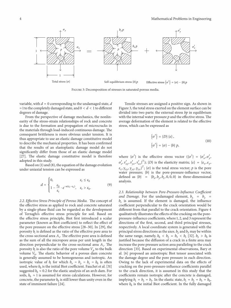
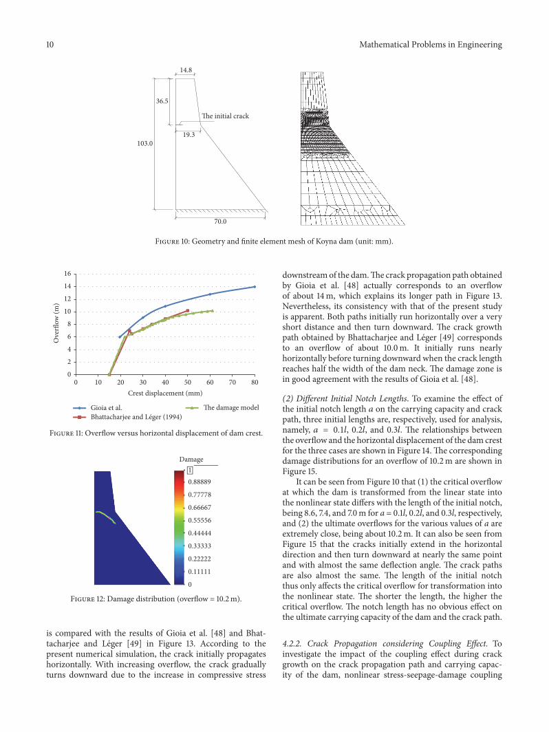
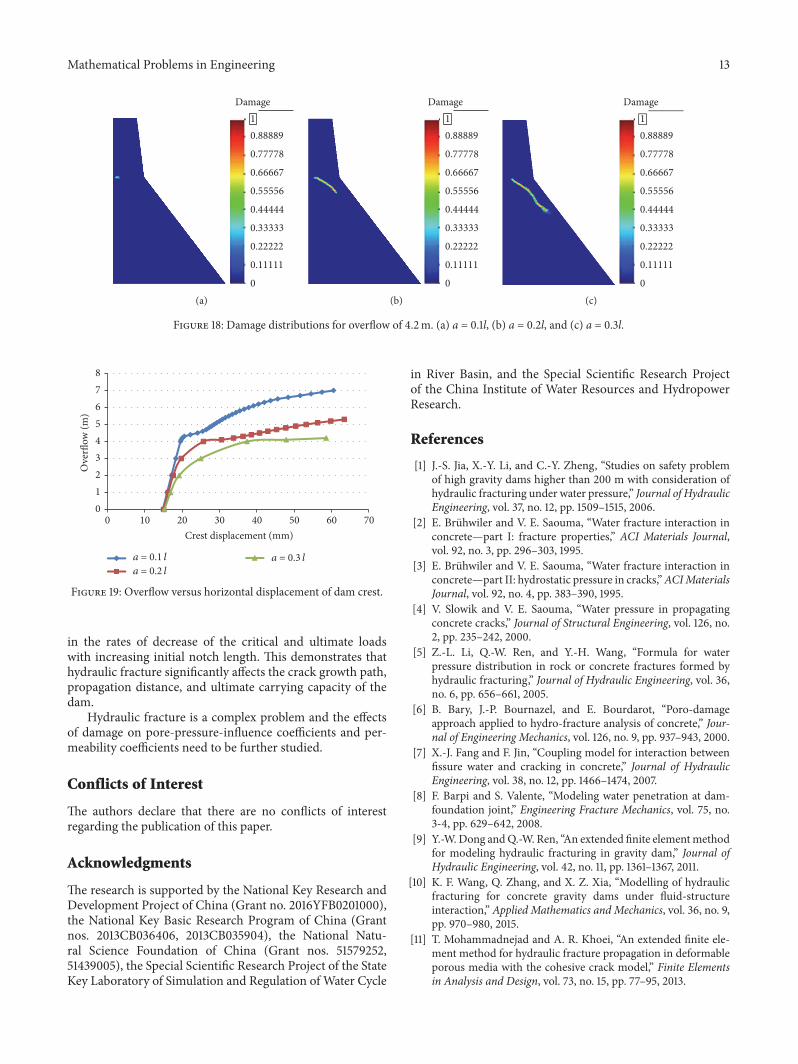