modeling of two-dimensional five-harness woven sic… · modeling of two-dimensional five-harness...
TRANSCRIPT
National Aeronautics and Space Administration
www.nasa.gov 1
Modeling of Two-dimensional Five-harness
Woven SiC/SiC Ceramic Matrix Composites
Subodh K. Mital
The University of Toledo
Toledo, Ohio, U.S.A.
Kuang C. Liu
Arizona State University
Tempe, Arizona, U.S.A.
Brett A. Bednarcyk and Steven M. Arnold NASA Glenn Research Center
Cleveland, Ohio, U.S.A.
https://ntrs.nasa.gov/search.jsp?R=20150009534 2018-06-18T13:29:03+00:00Z
National Aeronautics and Space Administration
www.nasa.gov 2
Outline
• Introduction/Background
• Analysis Methods
• Elastic Results
– Homogenized Composite Properties
– Local Stress Fields
• Creep Modeling
• Multi-Scale Generalized Method of Cells (MSGMC)
– Impact of material and architectural parameters on
composite properties
• Conclusions
National Aeronautics and Space Administration
www.nasa.gov 3
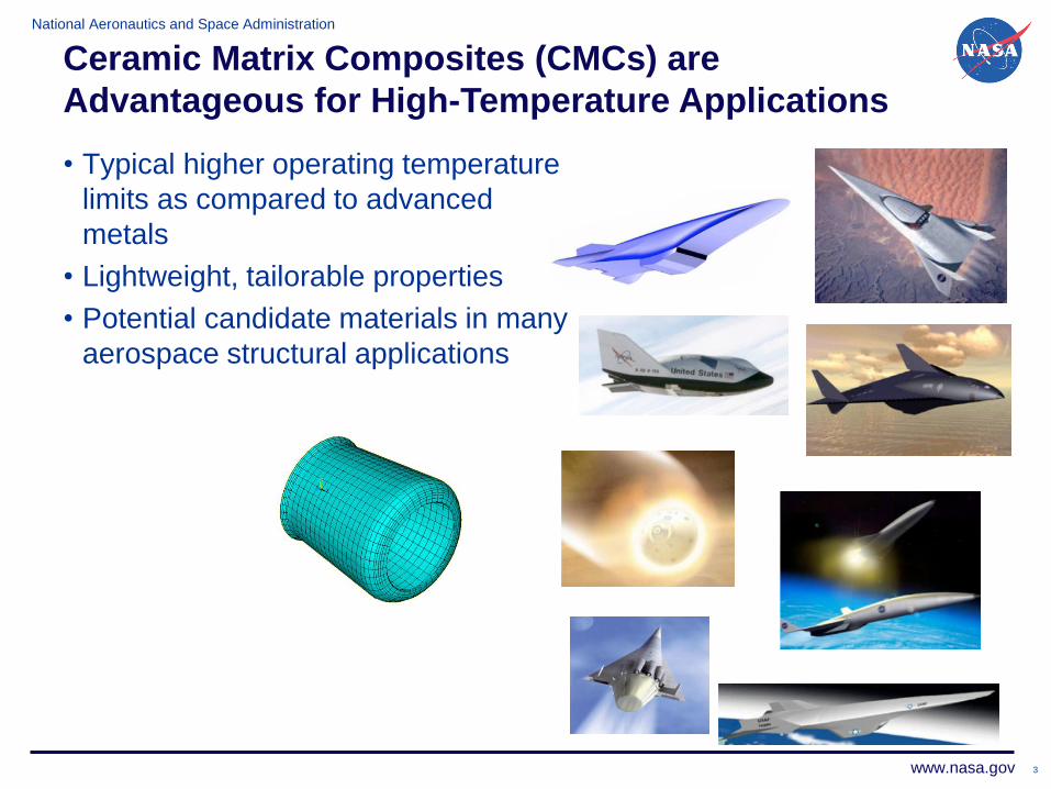
• Typical higher operating temperature
limits as compared to advanced
metals
• Lightweight, tailorable properties
• Potential candidate materials in many
aerospace structural applications
Ceramic Matrix Composites (CMCs) are
Advantageous for High-Temperature Applications

National Aeronautics and Space Administration
www.nasa.gov 4
Objective of Present Work: Examine and Assess
Approaches for Modeling Woven CMCs
• Material description –
– Fiber is woven in a fabric preform of desired
architecture such as plain weave, five-
harness satin weave
– Woven fabric is stacked in multiple layers
– An interfacial coating is deposited on all fiber
surfaces usually by a chemical vapor
infiltration (CVI) process
– The preform is then infiltrated by a silicon
carbide matrix using the CVI process
– The remaining porosity is filled either
continuing to deposit the SiC matrix uisng the
CVI process or in some cases using a slurry-
cast melt-infiltration (MI) process.
National Aeronautics and Space Administration
www.nasa.gov 5
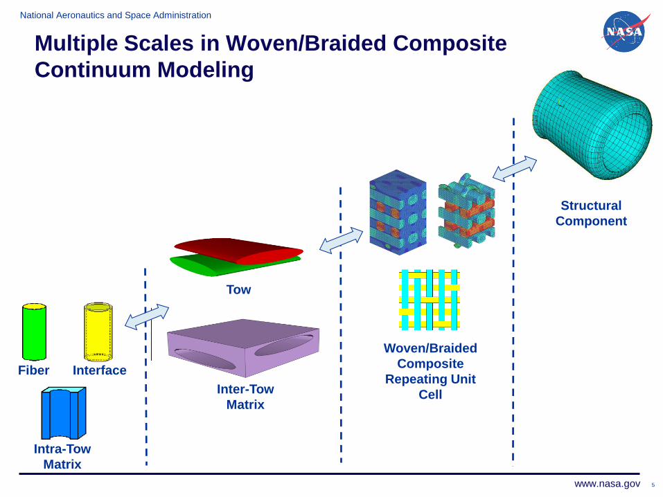
Multiple Scales in Woven/Braided Composite
Continuum Modeling
Fiber Interface
Intra-Tow
Matrix
Tow
Woven/Braided
Composite
Repeating Unit
Cell
Structural
Component
Inter-Tow
Matrix
National Aeronautics and Space Administration
www.nasa.gov 6
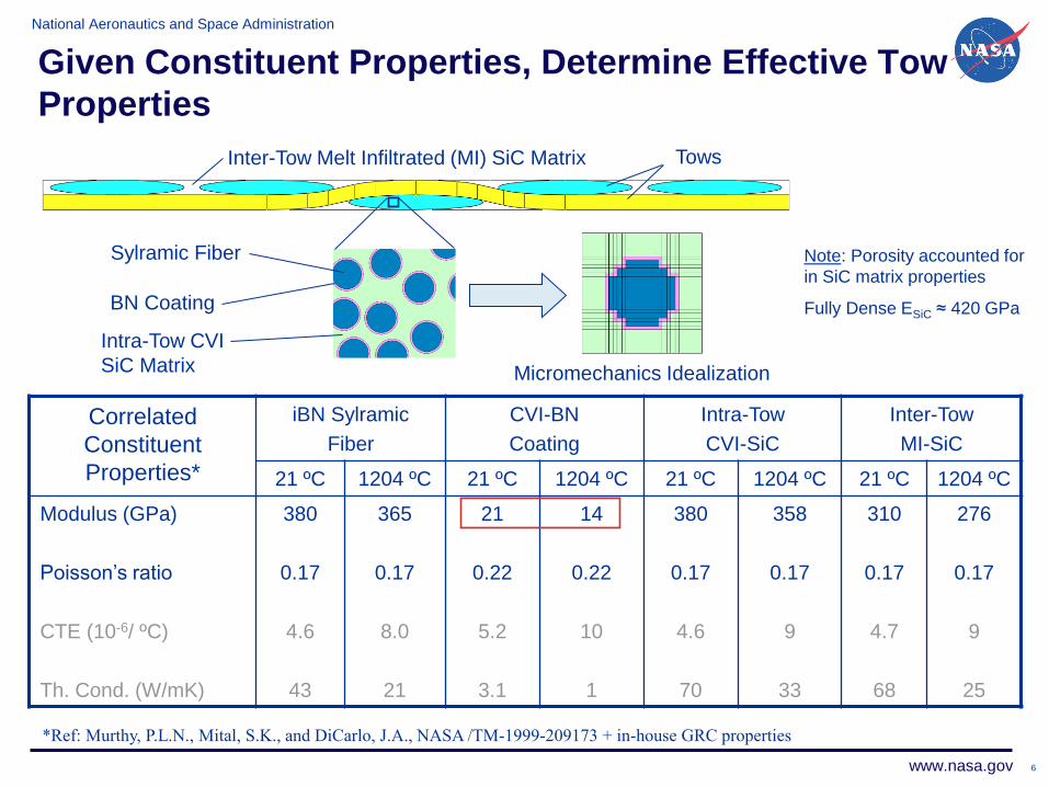
Given Constituent Properties, Determine Effective Tow
Properties
Inter-Tow Melt Infiltrated (MI) SiC Matrix
Sylramic Fiber
BN Coating
Intra-Tow CVI
SiC Matrix Micromechanics Idealization
Tows
Correlated
Constituent
Properties*
iBN Sylramic
Fiber
CVI-BN
Coating
Intra-Tow
CVI-SiC
Inter-Tow
MI-SiC
21 ºC 1204 ºC 21 ºC 1204 ºC 21 ºC 1204 ºC 21 ºC 1204 ºC
Modulus (GPa)
Poisson’s ratio
CTE (10-6/ ºC)
Th. Cond. (W/mK)
380
0.17
4.6
43
365
0.17
8.0
21
21
0.22
5.2
3.1
14
0.22
10
1
380
0.17
4.6
70
358
0.17
9
33
310
0.17
4.7
68
276
0.17
9
25
*Ref: Murthy, P.L.N., Mital, S.K., and DiCarlo, J.A., NASA /TM-1999-209173 + in-house GRC properties
Note: Porosity accounted for
in SiC matrix properties
Fully Dense ESiC ≈ 420 GPa

National Aeronautics and Space Administration
www.nasa.gov 7
Analysis Methods Vary Based on Capabilities, Fidelity,
and Computational Expense
• Micromechanics Based (Analytical) Methods –
– Laminate Approximation
– W-CEMCAN - Generalized Method of Cells (GMC)
• Also have High Fidelity Generalized
Method of Cells (HFGMC)
• Accounts for tow directionality
• Elliptical tow shape
• Account for tow undulation

National Aeronautics and Space Administration
www.nasa.gov
Analysis Methods Vary Based on Capabilities,
Fidelity, and Computational Expense
• Hybrid Methods –
• Numerical Methods (2-D and 3-D Finite Element Analyses)-
8
- User friendly
- Models many types of 2-D and
3-D architectures
- Accurate
- Inefficient and
expensive

National Aeronautics and Space Administration
www.nasa.gov 9
Elastic Properties at Room Temperature
Multiscale
Lam. Theory
W-
CEMCAN
GMC-3D HFGMC
pcGINA
FEA
Avg.
Exp.
Rect.
Tow
Cross
Tow
1-step 2-step 2-D 3-D 2-D 3-D
Ex (GPa) 254 253 266 233 252 253 247 248 253.7 251.9 252
Ey (GPa) 254 253 266 233 252 234 247 248 233.6 251.9 252
Ez (GPa) 183 180 178 183 183 163 183 174 163.3 180.2 ~82
xy 0.130 0.129 0.12 0.125 0.127 0.126 0.121 0.12 0.139 0.129 0.13
Gxy (GPa) 77.6 76.4 78 70.7 74.5 67.6 71.4 102 72.6 76.5 –
x (W/m-k) TBD TBD 42 37.4 41.3 TBD TBD 42 TBD TBD 50
z (W/m-k) TBD TBD 30 30.3 30.3 TBD TBD 32 TBD TBD 25
CTEx (10-6/ºC) TBD TBD 4.63 4.64 4.66 TBD TBD 4.2 TBD TBD 2.7
Ex. Time (s) 0.015 0.015 <1 0.08 – 0.22 2.9 ~4 60* 2640* –
*For 4 Load Cases
Note: Execution times based on Intel dual core X7900 @ 2.8 GHz, 4 GB RAM
Elastic properties within ~7%
Constituent properties known no better
Experimental repeatability no better

National Aeronautics and Space Administration
www.nasa.gov 10
Efficient Methods Still Give Reasonably Accurate
Approximations of Local Stress Fields
• Von Mises stress fields predicted by models
– 1204 ºC, applied in-plane strain of 0.1%
Multiscale Lam. Theory, Rect. Tow – 9 2D subcells per ply – 0.015 seconds
Multiscale Lam. Theory, Cross Tow – 25 2D subcells per ply – 0.015 seconds
HFGMC-3D – 400 3D subcells – 2.9 seconds
1-Step GMC-3D – 400 3D subcells – 0.08 seconds
HFGMC-2D – 656 2D subcells – 0.22 seconds
3D FEA – 172,406 3D Elements – 660 seconds
2D FEA – 3208 2D Elements – 15 seconds
Von Mises
Stress (MPa)
Loading Direction

National Aeronautics and Space Administration
www.nasa.gov
ImMAC Software Suite Integrated multiscale Micromechanics Analysis Code
• Consists of MAC/GMC (stand-alone), FEAMAC(implemented within
ABAQUS) and HyperMAC (implemented within HyperSizer) software
codes.
• ImMAC is software released by NASA GRC/RXL for multiscale
analysis of composite structures
• It links the behavior of a structure to the behavior of the composite
constituent materials
• The key link between the scales is micromechanics, which provides
the composite response based on the constituent behavior
Fiber Interface Matrix
Constituent
Response
Composite
Micromechanics
Repeating Unit Cell
Structural
Model
Homogenize
Localize
Homogenize
Localize

National Aeronautics and Space Administration
www.nasa.gov 12
Creep Modeling
• Multiscale Lamination Theory
– Rectangular tow
– Cross-shaped tow
• 2D FEA
Creep Parameters of Tows and Matrix Not Known
- Transversely isotropic power law creep model used to model creep of tows
- Five material parameters for transversely isotropic tows and three parameters for
isotropic matrix
- These parameters must be backed out from available measured composite creep
curves

National Aeronautics and Space Administration
www.nasa.gov 13
Efficiency is Critical when Backing Out Nonlinear
Model Parameters
• Typical to run hundreds of cases to determine parameters
– Used efficient Multiscale Lam. Theory approach to obtain parameters
• Utilized creep test results at 1315 ºC
• Isotropic MI SiC: T = 55 MPa, m = 3.71010 MPas, n = 1, h = 1, w = 1
• Trans. Iso. Tow: T = 6.9 MPa, m = 6.91010 MPas, n = 3.5, h = 5, w = 5
Experimental Creep Data, 1315 ºC Characterized Tow and MI SiC Creep Response
0.00
0.05
0.10
0.15
0.20
0.25
0.30
0.35
0 20 40 60 80 100 120 140
Creep Time (hours)
To
tal
Str
ain
(%
)
Experiment - 172 MPa
Experiment - 138 MPa
Experiment - 103 MPa
0.00
0.05
0.10
0.15
0.20
0.25
0.30
0.35
0 20 40 60 80 100 120 140
Creep Time (hours)
To
tal
Str
ain
(%
)Tow - Transverse - 34.5 MPa
Tow - Longitudinal - 172 MPa
MI SiC - 172 MPa

National Aeronautics and Space Administration
www.nasa.gov 14
Multiscale Lam. Theory Captures Primary and Secondary Creep,
Even Though Constituents have Only Secondary
• Stress redistribution from relaxation drives apparent primary creep
• Effect of tow shape representation much more pronounced
– Recall E affected only by ~0.5 %
Elongated Cross
Rectangular
Tow MI
Tow MI
• 2340 time increments
• Execution times:
– 0.6 seconds
– 1.0 seconds
0.00
0.05
0.10
0.15
0.20
0.25
0.30
0.35
0 20 40 60 80 100 120 140
Creep Time (hours)
To
tal
Str
ain
(%
)Experiment - 172 MPa
Lam. Theory - 172 MPa
Experiment - 138 MPa
Lam. Theory - 138 MPa
Experiment - 103 MPa
Lam. Theory - 103 MPa
Cross-shaped Tow
Rectangular Tow
Cross-shaped Tow
Rectangular Tow
Cross-shaped Tow
Rectangular Tow
National Aeronautics and Space Administration
www.nasa.gov 15
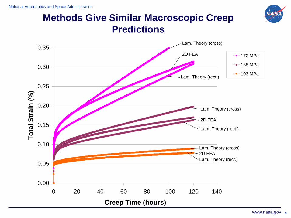
Methods Give Similar Macroscopic Creep
Predictions
0.00
0.05
0.10
0.15
0.20
0.25
0.30
0.35
0 20 40 60 80 100 120 140
Creep Time (hours)
To
tal S
train
(%
)
172 MPa
138 MPa
103 MPa
Lam. Theory (cross)
2D FEA
Lam. Theory (cross)
2D FEA
Lam. Theory (cross)
2D FEA
Lam. Theory (rect.)
Lam. Theory (rect.)
Lam. Theory (rect.)

National Aeronautics and Space Administration
www.nasa.gov
Fiber Interface
Intra-Tow
Matrix
Tow
Woven/Braided
Composite
Repeating Unit
Cell
Structural
Component
Inter-Tow
Matrix
Intra –Tow
Pore
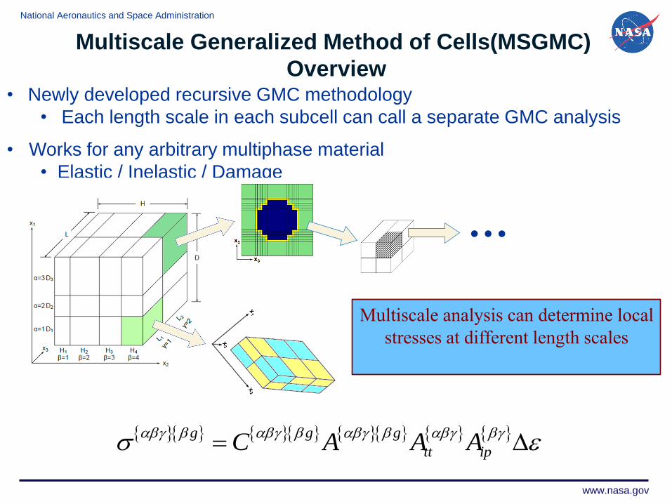
Multiscale Generalized Method of Cells (MSGMC) For
Concurrent Analysis of Woven/Braided Composites
National Aeronautics and Space Administration
www.nasa.gov
• Newly developed recursive GMC methodology
• Each length scale in each subcell can call a separate GMC analysis
• Works for any arbitrary multiphase material
• Elastic / Inelastic / Damage
Multiscale analysis can determine local
stresses at different length scales
1 1 1 1 1
1 1 1N NN N N
gh l d h l
hl d h l
= = = = =
=
1 1 1 1 1
1 1 1N NN N N
tt ipC C A h l A d A h lhl d h l
= = = = =
=
g g g
tt ipC A A A
=
…
Multiscale Generalized Method of Cells(MSGMC)
Overview

National Aeronautics and Space Administration
www.nasa.gov
Study Effects Of Micro, Meso, And Macro Parameters
on Macroscale Response
Architectural Parameter Relevant Length Scale Values
Tow Fiber Volume Fraction Meso 0.46,0.48,0.50
Tow Void Volume Fraction Meso 0.01,0.05,0.07
Tow Aspect Ratio Macro 8,10,12

National Aeronautics and Space Administration
www.nasa.gov
Range Of Macro Response Curves Given the 27
Variations In Architectural Parameters Utilized Localized Void Model
0
50
100
150
200
250
300
350
400
450
500
0 0.001 0.002 0.003 0.004 0.005
Str
ess
(MP
a)
Strain
TowVf=46%,AR=8,TowVv=1%
TowVf=46%,AR=8,TowVv=5%
TowVf=46%,AR=8,TowVv=7%
TowVf=46%,AR=10,TowVv=1%
TowVf=46%,AR=10,TowVv=5%
TowVf=46%,AR=10,TowVv=7%
TowVf=46%,AR=12,TowVv=1%
TowVf=46%,AR=12,TowVv=5%
TowVf=46%,AR=12,TowVv=7%
TowVf=48%,AR=8,TowVv=1%
TowVf=48%,AR=8,TowVv=5%
TowVf=48%,AR=8,TowVv=7%
TowVf=48%,AR=10,TowVv=1%
TowVf=48%,AR=10,TowVv=5%
TowVf=48%,AR=10,TowVv=7%
TowVf=48%,AR=12,TowVv=1%
TowVf=48%,AR=12,TowVv=5%
TowVf=48%,AR=12,TowVv=7%
TowVf=50%,AR=8,TowVv=1%
TowVf=50%,AR=8,TowVv=5%
TowVf=50%,AR=8,TowVv=7%
TowVf=50%,AR=10,TowVv=1%
TowVf=50%,AR=10,TowVv=5%
TowVf=50%,AR=10,TowVv=7%
TowVf=50%,AR=12,TowVv=1%
TowVf=50%,AR=12,TowVv=5%
TowVf=50%,AR=12,TowVv=7%
Architectural Variations
clearly contribute to
variation in measured
material response.
• Initial Modulus 24%
• UTS 2%
• 1st matrix cracking
16%
• Post matrix cracking
Modulus 24%
• f impacted 16%
16%
22%
72GPa
90GPa
National Aeronautics and Space Administration
www.nasa.gov 20
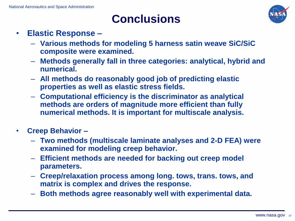
Conclusions • Elastic Response –
– Various methods for modeling 5 harness satin weave SiC/SiC composite were examined.
– Methods generally fall in three categories: analytical, hybrid and numerical.
– All methods do reasonably good job of predicting elastic properties as well as elastic stress fields.
– Computational efficiency is the discriminator as analytical methods are orders of magnitude more efficient than fully numerical methods. It is important for multiscale analysis.
• Creep Behavior –
– Two methods (multiscale laminate analyses and 2-D FEA) were examined for modeling creep behavior.
– Efficient methods are needed for backing out creep model parameters.
– Creep/relaxation process among long. tows, trans. tows, and matrix is complex and drives the response.
– Both methods agree reasonably well with experimental data.
National Aeronautics and Space Administration
www.nasa.gov 21
Conclusions (contd.)
• Multiscale Analysis of Woven Composites -
– Demonstrated that a synergistic analysis using the multiscale generalized method of cells (MSGMC) can accurately represent woven CMC tensile behavior (loading/unloading).
– Failure mechanisms are captured via local continuum damage model.
– Variations in Weave Parameters (micro, meso, and macro) appear to contribute to variation in measured material macrolevel response.