modelling and performance analysis of advanced combined...
TRANSCRIPT

Modelling and performance analysis of advancedcombined co-phase traction power supply systemin electrified railwayChen, Minwu; Li, Qunzhan; Roberts, Clive; Hillmansen, Stuart; Tricoli, Pietro; Zhao, Ning;Krastev, IvanDOI:10.1049/iet-gtd.2015.0513
License:None: All rights reserved
Document VersionPublisher's PDF, also known as Version of record
Citation for published version (Harvard):Chen, M, Li, Q, Roberts, C, Hillmansen, S, Tricoli, P, Zhao, N & Krastev, I 2016, 'Modelling and performanceanalysis of advanced combined co-phase traction power supply system in electrified railway' IET Generation,Transmission and Distribution, vol 10, no. 4, pp. 906-916. DOI: 10.1049/iet-gtd.2015.0513
Link to publication on Research at Birmingham portal
General rightsUnless a licence is specified above, all rights (including copyright and moral rights) in this document are retained by the authors and/or thecopyright holders. The express permission of the copyright holder must be obtained for any use of this material other than for purposespermitted by law.
•Users may freely distribute the URL that is used to identify this publication.•Users may download and/or print one copy of the publication from the University of Birmingham research portal for the purpose of privatestudy or non-commercial research.•User may use extracts from the document in line with the concept of ‘fair dealing’ under the Copyright, Designs and Patents Act 1988 (?)•Users may not further distribute the material nor use it for the purposes of commercial gain.
Where a licence is displayed above, please note the terms and conditions of the licence govern your use of this document.
When citing, please reference the published version.
Take down policyWhile the University of Birmingham exercises care and attention in making items available there are rare occasions when an item has beenuploaded in error or has been deemed to be commercially or otherwise sensitive.
If you believe that this is the case for this document, please contact [email protected] providing details and we will remove access tothe work immediately and investigate.
Download date: 19. May. 2018

Modelling and performance analysis ofadvanced combined co-phase traction powersupply system in electrified railway
ISSN 1751-8687Received on 15th April 2015Revised on 22nd July 2015Accepted on 31st July 2015doi: 10.1049/iet-gtd.2015.0513www.ietdl.org
Minwu Chen1 ✉, Qunzhan Li1, Clive Roberts2, Stuart Hillmansen2, Pietro Tricoli2, Ning Zhao2,
Ivan Krastev2
1School of Electrical Engineering, Southwest Jiaotong University, Chengdu, People’s Republic of China2School of Electronic, Electrical and Systems Engineering, University of Birmingham, Birmingham, UK
✉ E-mail: [email protected]
Abstract: An advanced combined co-phase traction power supply system is proposed by combining a single-phasetraction transformer and an active power flow controller (PFC) in an electrified railway. In the new system, the powerquality problems caused by single-phase traction load are solved in the grid side and continuous power can beprovided to electric trains without neutral sections in the traction side. The mathematic model of the new system isbuilt by power transformation analysis. The compensation currents of the PFC are calculated based on the powerbalance principle. According to the power quality standard in China, the optimised partial compensation algorithm ispresented to replace the existing full compensation one. Moreover, the capacity of the PFC adopting the proposedalgorithm is much less than those in the previous studies with the same outcome. The validity of the compensationalgorithm and the control method are demonstrated by the simulation results and the effectiveness of the proposedsystem is verified by the case studies.
1 Introduction
The single-phase 25 kV AC traction power supply system (TPSS),which performs the power and voltage transformation for electrictrains, has been widely adopted in the electrified railway[1]. Tomeet the requirements of high speed and heavy haul transportationthroughout Europe and China, new high power locomotives andelectric multiple units have been designed and applied in mainlines [2–5]. As a result of the high power requirements, a largeunbalanced current is injected into the power grid and thethree-phase voltage unbalance is serious, especially in some areaswith a weak power grid [6, 7]. Meanwhile, a large number ofexisting DC powered locomotives generate reactive power anddecrease the power factor (PF), which can make the tractiontransformer work in a derated state and increase the powertransmission losses [8]. Once the average PF of a tractionsubstation is <0.9, a high penalty will be applied [9]. In addition,as an outstanding obstacle in conventional TPSS, the electricallyisolated sections, called neutral sections at exits of substations, cancause serious problems including over-voltage, magnetising inrushcurrent, speed loss of locomotives and even phase mixingaccidents [10, 11].
Various technologies for solving these problems have beeninvestigated in recent years. Some special balanced tractiontransformers have been presented [12–14]. Unfortunately, thetraction loads at traction side are seldom balanced due to thevariable number, speed and location of locomotives. Comparedwith the single-phase traction transformer, the complex connectionconfiguration and the low capacity availability of the new modelsalso prohibit their practical application. Compensator-basedtechnologies have been adopted and the power quality has beenimproved in the TPSS [15–18]. However, in these studies thethree-phase to two-phase traction power supply scheme was stilladopted and the electrically isolated section was alsoindispensable. Recently, a co-phase TPSS has been proposed andan actual 10 MVA/27.5 kV co-phase system withimpedance-matching balance transformer has been designed,
developed and tested in an operating railway in China [19–21]. Ina co-phase TPSS, the traction load can be fed by the tractiontransformer with single loading phase and the neutral sections canbe subsequently eliminated. Furthermore, power qualitycompensation can be carried out by the power flow controller(PFC). Three-phase balance and unity PF in the grid side can thenbe achieved. However, the main obstacle for promoting a co-phaseTPSS is high initial cost caused by large capacity of the PFC forfull compensation. In [22, 23], hybrid compensation technologywas introduced in the topology design to decrease the capacity ofthe PFC. Nevertheless, the continuous adjustment of the mainparameters of the passive device is difficult and dynamiccompensation effectiveness is affected with the time-variedtraction load. In fact, according to the power quality standard inChina, partial compensation is more suitable for the tractionsupply system [24, 25] rather than full compensation in [19, 20].A partial reactive power compensation model of a co-phasetraction power system has been presented and the compensationcurrents of the PFC have been derived in [24]. However, thecapacity of the PFC is related to not only the reactive powercompensation but also the balanced power compensation. In [25],a compensating algorithm for the PFC has been proposed withreactive and unbalanced power reducing ratios. With differentcompensation objectives, various capacity configuration schemeshave been discussed separately. Nonetheless, the compensationtargets are expressed by the specified limiting values of PF andthree-phase voltage unbalance after compensation is more popularfor the control system design, whereas a universal compensationmodel is still lacking for compensation currents calculation. Inaddition, by working together with the PFC for continuous tractionpower supply, the installed capacity of the traction transformer canbe degraded and the corresponding tariff can be reducedsignificantly, especially for high speed and heavy haul railways inChina. Compared with complex three-phase to two-phase tractiontransformers, the simplest single-phase transformer with low costand high capacity utilisation ratio is more attractive for co-phasetraction supply system [26].
IET Generation, Transmission & Distribution
Research Article
IET Gener. Transm. Distrib., 2016, Vol. 10, Iss. 4, pp. 906–916906 & The Institution of Engineering and Technology 2016
In this paper, a combined co-phase TPSS using a single-phasetraction transformer and active PFC is presented. The single-phasetraction transformer can provide the main power for traction loadand PFC is mainly used for power quality compensation. Athree-phase set-up transformer is used in PFC instead of theconventional single-phase transformer and can change the voltagephase angle of input port of PFC. On one hand, the excellentbalanced characteristic of new system can be achieved by adoptingthe three-phase set-up transformer, which can reduce the capacityand the cost of PFC especially for unbalanced powercompensation. On another hand, the size and cost of differentset-up transformers are mainly related with the rated voltage andcapacity. Although there are some differences in connectioncomplexity and installation, they are easily manufactured andwidely used. To analyse the performance, the mathematic modelof the new system is built based on a three-phase to single-phasepower transformation method. The compensation currents of PFCare deduced and expressed by the limiting values of three-phasevoltage unbalance ratio and PF after compensation. The optimisedpartial compensation algorithm is proposed for minimising PFCcapacity as well as the cost according to the power qualitystandard. Simulation results verify the viability of thecompensation algorithm and control method. Moreover, the casestudies show the higher effectiveness of the proposed systemcompared with the conventional TPSS.
2 Modelling of combined co-phase traction powersupply system
2.1 Electrical structure of combined co-phase tractionpower supply system
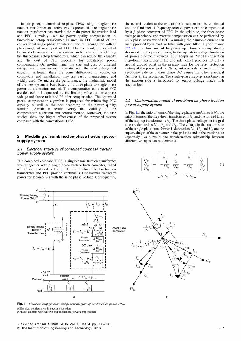
In a combined co-phase TPSS, a single-phase traction transformerworks together with a single-phase back-to-back converter, calleda PFC, as illustrated in Fig. 1a. On the traction side, the tractiontransformer and PFC provide continuous fundamental frequencypower for locomotives with the same phase voltage. Consequently,
the neutral section at the exit of the substation can be eliminatedand the fundamental frequency reactive power can be compensatedby a β phase converter of PFC. In the grid side, the three-phasevoltage unbalance and reactive compensation can be performed byan α phase converter of PFC. Assuming the harmonic current canbe suppressed by a reactive filter with good filtering performance[22–24], the fundamental frequency operations are emphaticallydiscussed in this paper. Owing to the operation voltage limitationof power electronic devices, PFC adopts an YNd11 connectionstep-down transformer in the grid side, which provides not only aneutral ground point in the primary side for the relay protectionsetting of the power grid in China, but also a delta winding in thesecondary side as a three-phase AC source for other electricalfacilities in the substation. The single-phase step-up transformer inthe traction side is introduced for output voltage match withtraction bus.
2.2 Mathematical model of combined co-phase tractionpower supply system
In Fig. 1a, the ratio of turns of the single-phase transformer is N1, theratio of turns of the step-down transformer is N2 and the ratio of turnsof the step-up transformer is N3. The three-phase voltages in the gridside are denoted as UA, UB and UC . The voltage in the traction sideof the single-phase transformer is denoted as UT. Ua and Ub are theinput voltages of the converter in the grid side and in the traction sideseparately. As a result, the transformation relationship betweendifferent voltages can be derived as
UTUa
Ub
⎡⎣
⎤⎦ =
1
N10 − 1
N1
− 1
3N2
2
3N2− 1
3N2
1
N1N30 − 1
N1N3
⎡⎢⎢⎢⎢⎢⎢⎣
⎤⎥⎥⎥⎥⎥⎥⎦
UA
UB
UC
⎡⎣
⎤⎦ (1)
Fig. 1 Electrical configuration and phasor diagram of combined co-phase TPSS
a Electrical configuration in traction substationb Phasor diagram with reactive and unbalanced power compensation
IET Gener. Transm. Distrib., 2016, Vol. 10, Iss. 4, pp. 906–916907& The Institution of Engineering and Technology 2016

where
UA = UAej0◦
UB = UAe−j120◦
UC = UAej120◦
⎧⎪⎨⎪⎩ (2)
The three-phase currents in the grid side are denoted as I A, I B and IC .I T1 is the primary current of the single-phase transformer, I A1, I B1and IC1are the input currents of PFC in the grid side. Therefore,(3) is deduced
I A = I A1 + IT1I B = I B1IC = IC1 − IT1
⎧⎨⎩ (3)
where
IT1 =1
N1IT2 (4)
I A1I B1IC1
⎡⎣
⎤⎦ = 1
N2
I a2I b2I c2
⎡⎣
⎤⎦ (5)
Assuming that ZAO−a2, ZBO−b2 and ZCO−c2 are the equivalentimpedances of windings in the YNd11 transformer and satisfyZAO−a2 = ZBO−b2 = ZCO−c2. I a2, I b2 and I c2 are the currents in thedelta winding, Iaand Ib are the compensation currents provided bythe PFC. As a result, (6) can be obtained
I a2I b2I c2
⎡⎣
⎤⎦ =
− 1
32
3
− 1
3
⎡⎢⎢⎢⎢⎢⎣
⎤⎥⎥⎥⎥⎥⎦Ia (6)
By substituting (6) to (3), the three-phase currents in the grid side canbe calculated by the following equation
I AIBIC
⎡⎣
⎤⎦ =
1
N1− 1
3N2
02
3N2
− 1
N1− 1
3N2
⎡⎢⎢⎢⎢⎢⎢⎣
⎤⎥⎥⎥⎥⎥⎥⎦
IT2Ia
[ ](7)
By using the method of symmetrical components, the negativesequence components can be determined and expressed as
I0I A2I A1
⎡⎣
⎤⎦ =
0 01− a
3N1
a2
3N2
1− a2
3N2
a
3N2
⎡⎢⎢⎢⎢⎢⎣
⎤⎥⎥⎥⎥⎥⎦
IT2Ia
[ ](8)
where a = ej120°. Take UA as a reference, the negative current in gridside is revised as
I A2 =1��3
√N1
ej(−30◦) IT2 +1
3N2ej240
◦Ia
= 1��3
√N1
e−j(60◦+wT)IT2︸����������︷︷����������︸PartI
+ 1
3N2ej(120
◦−wa)Ia︸��������︷︷��������︸PartII
(9)
The negative current can be decomposed to the component part Icaused by the power flow via the single-phase traction transformerand the component part II caused by the power flow via α phaseconverter of the PFC. With the phase difference, the twocomponents are able to cancel each other out. Therefore, thesingle-phase traction transformer can work together with the PFCand the unbalanced power compensation can be performed in thegrid side.
In the traction side, the β phase converter of the PFC can not onlyperform the reactive power compensation but also supply activepower for the traction load when the α phase converter absorbs itfrom the grid. In Fig. 1b, each current can be decomposed to ap-axis component and a q-axis component by taking its supplyvoltage as a reference and expressed as
Ia = Iap + jIaqIb = Ibp + jIbqIT2 = ITp + jITqIL = ILp + jILq
⎧⎪⎪⎪⎪⎨⎪⎪⎪⎪⎩
(10)
Using the power balance method, (11) and (12) are deduced
UTITp + UbIbp = UTILpUTITq + UbIbq = UTILq
{(11)
UaIap = UbIbp (12)
2.3 Comprehensive compensation currents calculation
2.3.1 Compensation targets: Generally, in the design stage ofelectrified railways in China, the short-circuit capacity known asSand rated line-to-line voltage known as US in the grid side areknown, as well as the traction load current IL with PF angle jL.The limiting values of the PF and voltage unbalanced ratio aftercompensation are given and expressed as K and ɛU, the so-calledcomprehensive compensation targets. According to power qualitystandards in China [27], the voltage unbalance ratio ɛU can beestimated by the following equation
1U =��3
√IA2∣∣ ∣∣US
S× 100% (13)
In (13), owing to the traction load supplied by a single-phase tractiontransformer and not completely compensated by the PFC, thenegative sequence current still exists. By substituting (9) to (13),(14) is deduced
S1U100
��3
√US
e−j(60◦+wL) = 1��3
√N1
e−j(60◦+wT)IT2 +1
3N2ej(120
◦−wa)Ia
(14)
Meanwhile, the reactive power compensation can be performed andthe PF after compensation in the grid side can be calculated by thefollowing equation
K = UTITp + UaIap�����������������������������������������(UTITp + UaIap)
2 + (UTITq + UaIaq)2
√ (15)
2.3.2 Compensation currents calculation: According to(11)–(15), the following three groups of equations can describe theoperating characteristics of a combined co-phase traction supplysystem using the power balance principle.
IET Gener. Transm. Distrib., 2016, Vol. 10, Iss. 4, pp. 906–916908 & The Institution of Engineering and Technology 2016
The first group consists of active power balance equations and canbe written as
UTITp + UaIap = UTILpUTITp + UbIbp = UTILp
{(16)
The second group consists of reactive power balance equations andcan be written as
UTILp�������������������������������(UTILp)
2 + (UTITq + UaIaq)2
√ = K
UTITq + UbIbq = UTILq
⎧⎪⎨⎪⎩ (17)
The third group consists of unbalanced currents equations revisedfrom (14), and the active and reactive components can be written as
n1 = b1
2ITp +
��3
√
2ITq
( )+ c − 1
2Iap −
��3
√
2Iaq
( )
n2 = b1
2ITq −
��3
√
2ITp
( )+ c − 1
2Iaq +
��3
√
2Iap
( )⎧⎪⎪⎪⎨⎪⎪⎪⎩ (18)
where
a = S1U100
��3
√US
b = 1��3
√N1
c = 1
3N2
n1 = a× cos(− 60◦ + wL)n2 = a× sin(− 60◦ + wL)
⎧⎪⎪⎪⎪⎪⎪⎪⎪⎪⎪⎪⎪⎪⎨⎪⎪⎪⎪⎪⎪⎪⎪⎪⎪⎪⎪⎪⎩
(19)
According to (16)–(19), the operation current of the single-phasetraction transformer and the compensation currents of the PFC canbe achieved and written as follows
ITp =n1 −
��3
√n2 − m1 +
��3
√m2
4b
ITq =��3
√n1 + n2 −
��3
√m1 − m2
4bIap = m3(ILp − ITp)
Iaq = −m3
������������d2 − (ILp)
2√
+ ITq
( )Ibp = N3(ILp − ITp)Ibq = N3(ILq − ITq)
⎧⎪⎪⎪⎪⎪⎪⎪⎪⎪⎪⎪⎪⎪⎨⎪⎪⎪⎪⎪⎪⎪⎪⎪⎪⎪⎪⎪⎩
(20)
where
d = ILpK
m1 = − 1
2��3
√N1
ILp −1
2N1
���������d2 − I2
Lp
√m2 =
1
2N1ILp −
1
2��3
√N1
���������d2 − I2
Lp
√m3 =
��3
√N2
N1
⎧⎪⎪⎪⎪⎪⎪⎪⎪⎪⎪⎪⎨⎪⎪⎪⎪⎪⎪⎪⎪⎪⎪⎪⎩
(21)
2.4 Optimisation of compensation algorithms
2.4.1 Full compensation algorithm: In previous studies, a fullcompensation algorithm is popular for a co-phase TPSS [19, 20],which means the PF is equal to one and three-phase voltageunbalance ratio is equal to zero after compensation. Subsequently,the single-phase to three-phase symmetric power transformationcan be performed and the power quality problems can be solvedcompletely. According to (20) and (21), the currents can becalculated and expressed in the following equation
ITp =1
2ILp
ITq = 0
Iap =��3
√N2
2N1ILp
Iaq = 0
Ibp =N3
2ILp
Ibq = N3ILq
⎧⎪⎪⎪⎪⎪⎪⎪⎪⎪⎪⎪⎪⎪⎨⎪⎪⎪⎪⎪⎪⎪⎪⎪⎪⎪⎪⎪⎩
(22)
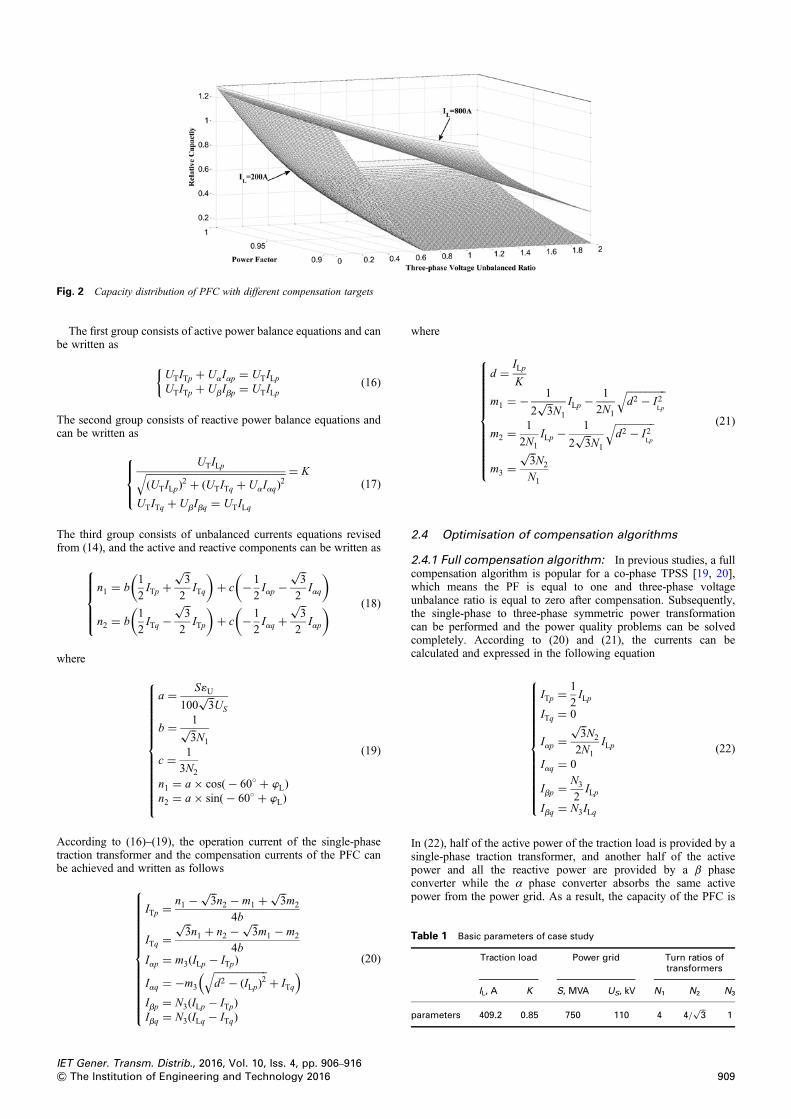
In (22), half of the active power of the traction load is provided by asingle-phase traction transformer, and another half of the activepower and all the reactive power are provided by a β phaseconverter while the α phase converter absorbs the same activepower from the power grid. As a result, the capacity of the PFC is
Fig. 2 Capacity distribution of PFC with different compensation targets
Table 1 Basic parameters of case study
Traction load Power grid Turn ratios oftransformers
IL, A K S, MVA US, kV N1 N2 N3
parameters 409.2 0.85 750 110 4 4/��3
√1
IET Gener. Transm. Distrib., 2016, Vol. 10, Iss. 4, pp. 906–916909& The Institution of Engineering and Technology 2016

calculated in the following equation
SPFC = Sa + Sb
= UaIa + UbIb
= 1
2+
����������������1+ 3( sinwL)
2√
2 coswL
⎛⎝
⎞⎠PL (23)
Assuming S = 750 MVA and US = 110 kV, when IL = 200A andIL = 800A as well as K = 0.85, Fig. 2 illustrates the capacity
distribution of the PFC expressed by SPFC/PL. According to (23),the maximum relative capacity of the PFC is a constant for the fullcompensation.
2.4.2 Partial compensation algorithm: The PF and thethree-phase voltage unbalance ratio caused by the traction load aretime varied. Assuming that Kset and 1U set are set as thecompensation targets in advance, when the instantaneousthree-phase voltage unbalance ratio is less than 1U set and the PF islower than the Kset, only the reactive power compensation is activeand the actual compensation targets can be revised in the
Table 2 Comparisons between new system and proposed system in [24]
ɛtarget Ktarget IA, A IB, A IC, A Uα, kV Uβ, kV Iα, A Iβ, A SPFC, per unit
case 1 in [24] 0.123 1 50.4 48.7 51.5 337.4 437.4 1case 1 in this paper (full compensation) 0.123 1 50.3 46.2 54.5 159.9 261.2 0.543case 2 in [24] 1.13 0.95 69.7 27.4 62.7 27.5 27.5 189.7 302.6 1case 2 in this paper (partial compensation) 1.13 0.95 78.1 14.2 89.5 49.2 88.3 0.279
Fig. 3 Cascade H-bridge chain topology of PFC
Fig. 4 Control system of PFC with optimised partial compensation algorithm
Table 3 Basic parameters of power grid and traction load with compensation targets
Setting Power grid Traction load Full compensation Optimisedcompensation
S, MVA US, kV SL, MVA K Kset ɛset Kset ɛset
case 1 500 110 10 0.8 1 0 0.9 2case 2 20 0.85case 3 30 0.9
IET Gener. Transm. Distrib., 2016, Vol. 10, Iss. 4, pp. 906–916910 & The Institution of Engineering and Technology 2016

following equation
1target =UTILS
× 100%
Ktarget = Kset
⎧⎪⎨⎪⎩ (24)
Similarly, when the instantaneous PF is higher than Kset and thethree-phase voltage unbalance ratio is more than 1U set, onlyunbalanced power compensation is active and the actual
compensation targets can be revised in the following equation
1target = 1U set
Ktarget = cos (wL)
{(25)
2.4.3 Optimised algorithm for minimum compensationcapacity: According to the power quality standard, thethree-phase voltage unbalance ratio should be no more than 2% inthe grid side. Moreover, the PF should be no <0.9. Thedistribution is shown in Fig. 2; taking these limiting values as thetargets, the capacity of the PFC can be decreased effectively underpartial compensation compared with that under full compensation.
In [24], a partial compensation algorithm was proposed fordecreasing the active compensation capacity. The basic parametersof case studies in [24] and the turn rations of all transformers inFig. 1 are shown in Table 1. The values of Uα and Uβ are 27.5.Comparisons between the new system adopting the proposedoptimised algorithm in this paper and the proposed system underpartial compensation in [24] have been performed and the detailsare shown in Table 2. It is significant to find that the capacity ofthe PFC can be decreased down to 54.3 and 27.9% separately withthe full and partial compensations. As a result, the viability of thenew system can be verified.
Table 4 Main circuit parameters of PFC
Parameters Values
α phase voltage Uα 10 kVα phase inductor Lα 20 mHDC capacitor CDC 40 000 μFDC link voltage 3 kVnumber of H-bridges N 15β phase voltage Uβn (n = 1 ,…, N) 2 kVβ phase inductor Lβn (n = 1 ,…, N ) 3 mHratio of turns N1 4ratio of turns N2 6.35ratio of turns N3 14
Fig. 5 Traction load with time-varying characteristics
Fig. 6 Three-phase currents in power grid side
a Full compensation simulationb Optimised compensation simulation
IET Gener. Transm. Distrib., 2016, Vol. 10, Iss. 4, pp. 906–916911& The Institution of Engineering and Technology 2016

Fig. 7 Operation currents of combined co-phase TPSS
a Current of α phase converter in PFCb Current of β phase converter in PFCc Current of single-phase traction transformer
Table 5 Comparison between simulation and calculation
Setting Full compensation
IT Iα Iβ
ITC, A ITM, A δ, % IαC, A IαM, A δ, % IβC, A IβM, A δ, %
case 1 145.5 156.8 7 145.5 151.1 3.8 262.2 258.5 1.4case 2 309.1 320.5 3.7 309.1 313.5 1.4 492.3 490.5 0.36case 3 490.9 507.5 3.4 490.9 495.3 0.89 683.5 679.1 0.64
Optimised compensationcase 1 341.9 349.5 2.2 38.6 42.2 9.3 38.6 41.2 6.7case 2 524.6 531.5 1.3 163.7 169.8 3.7 206.9 201.5 2.6case 3 727.3 733.8 0.9 363.6 366.1 0.7 363.6 356.5 1.9
IET Gener. Transm. Distrib., 2016, Vol. 10, Iss. 4, pp. 906–916912 & The Institution of Engineering and Technology 2016

3 Topology and control method of PFC
3.1 Optimised topology
A special topology for the PFC is proposed and shown in Fig. 3. Thecascade H-bridge chain is correct for high voltage and high capacitypower converters, in which the input voltage can be up to 10 kV in thepower grid side [28] and the capacity can be more than tens of MVAwith its inherent modularity and scalability [29]. In the DC link, thecapacitor of each H-bridge can be set independently and the voltage of
it can be controlled separately. With the recent fast development ofmodular multilevel converter (MMC) technology, a high number oflevels with the advantages of modular design, low switching frequencyand high efficiency can be adopted in the converter and the step-uptransformer can be removed subsequently, which will be a betteralternative scheme in the future [30]. Some single-phase MMC-basedconfigurations are discussed in [31]. To improve the stability and DClink voltage balance of MMC, the emerging research on controlstrategies have been demonstrated in [32, 33]. Therefore, MMC-basedcombined co-phase TPSS has broad prospects.
Fig. 8 Power quality test in a traction substation of a heavy haul railway in China
a Main circuit and test points (marked by filled triangle)b Equipments connection and layout in field
Fig. 9 Three-phase voltage unbalance ratio distribution in whole day
Fig. 10 PF distribution in whole day
IET Gener. Transm. Distrib., 2016, Vol. 10, Iss. 4, pp. 906–916913& The Institution of Engineering and Technology 2016

3.2 Control method
The control diagram of the PFCwith the reactive power and unbalanceoptimised partial compensation algorithm is illustrated in Fig. 4. In theactive and reactive currents detectionmodule, the instantaneous activecurrent iLp(t), the reactive current iLq(t) and the apparent power s(t)are calculated based on various detection methods with little timedelay and high precision [20, 22–24]. In the PF compensationmodule, the instantaneous K(t) is dynamically calculated.Comparing K(t) and Kset, the actual reactive compensation targetKtarget can be adjusted to minimise reactive compensation capacity.In the three-phase voltage unbalance compensation module,comparing ɛ(t) and ɛset, the actual unbalance compensation targetɛtarget can be adjusted to inimise unbalance compensation capacity.Thus, the compensation currents can be computed in real time. The
DC link controller module is designed for the steady operation ofthe PFC by controlling the voltage of the DC link capacitor, andidc(t) depends on the difference between the DC-link voltage udc(t)and reference voltage udc ref (t) under a proportional–integralregulator. The pulse-width modulation generator module cancontrol power modules generating accurate currents to track thecontrol references.
4 Simulation
The time-domain simulation of the combined co-phase TPSS isperformed in a MATLAB environment. The parameters of thepower grid and traction load, as well as limiting values of the
Fig. 11 Operation currents distribution of combined co-phase TPSS
a Compensation current of PFC in traction sideb Compensation current of PFC in power grid sidec Load current of traction transformer
IET Gener. Transm. Distrib., 2016, Vol. 10, Iss. 4, pp. 906–916914 & The Institution of Engineering and Technology 2016

power quality are shown in Table 3. The main circuit parameters ofthe PFC are shown in Table 4. Three cases studies are considered tocompensate three different characteristics of the traction load. In case1, the apparent power of the traction load SL is 10 MVA and the PF Kis 0.8, which can simulate the load characteristics of DC poweredelectrical locomotives widely used in China. In case 2, SL equals20 MVA and K equals 0.85, which can simulate the loadcharacteristics of a mix of DC and AC powered electricallocomotives in main lines. In case 3, SL equals 30 MVA andK equals 0.9, which can simulate the load characteristics of ACpowered electrical locomotives applied for high-speed railwaysand heavy haul railways. The time-varying traction load in thetraction side is shown in Fig. 5. The three-phase currents in thegrid side under full compensation and optimised operation areshown in Fig. 6. The operation current of the single-phase tractiontransformer and compensation currents of the PFC are shown inFig. 7. A comparison between the simulation and calculation isshown in Table 5 and all the current values are equivalent basedon a level of 27.5 kV. The variables with subscript ‘C’ and ‘M’,respectively, represent the calculation values and simulationvalues. Then, the error values can be achieved. The simulationresults using different compensation algorithms are approximatelyin agreement with the theoretical calculation values. Thus, themathematical model of the combined co-phase TPSS is verified. Inaddition, the application of the optimised compensation algorithmcan decrease the compensation currents of the PFC effectivelycompared with the full compensation algorithm. Subsequently, thepower quality problems caused by an electrified railway can besolved with low compensation capacity as well as low cost.
5 Case study
The short-circuit capacity of the power grid is generally low inmid-western China and the power quality problems caused by theelectrified railway are serious. Taking a heavy-haul railway as anexample, the field test was performed in a substation as shown inFig. 8. According to the measurement method in [26], each sampleis saved every 3 s by a professional power quality monitor. Fig. 9shows the three-phase voltage unbalance ratio distribution in thegrid side for a whole day, in which the ascending sort curve isgiven and 95% probability maximum value is marked comparedwith the limiting value 2%. Fig. 10 shows the PF distribution andthe limiting value 0.9 is marked. Obviously, the penalty fee willbe very high without the reactive compensation. Consequently, thecombined co-phase TPSS is a better alternative. Fig. 11 showsthe operation currents distribution adopting the new system andthe comparison is shown in Table 6. By working together with thePFC, the peak power provided by the traction transformer can bedecreased to 35.7% with the full compensation and 45.3% withthe optimised compensation. Meanwhile, root-mean-square (RMS)power can be decreased to 39.5 and 55.3%, respectively.Subsequently, the installed capacity of the traction transformer andthe relevant basic tariff can be saved significantly. In addition,under the optimised partial compensation, the capacity of the PFC
can be saved by up to 19% as well as the cost reduced. As aresult, the effectiveness of a combined co-phase TPSS is verified.
6 Conclusion
A 25 kV AC combined co-phase TPSS is discussed in this paper.Using a single-phase traction transformer and active PFC, thepower quality can be improved significantly and the neutralsections at exits of substations can be eliminated completely.
A mathematical model of the new system has been built andtransformation relationships of electrical parameters have beenderived. Subsequently, the operation currents provided by thesingle-phase traction transformer and the compensation currentsprovided by the PFC have been calculated with differentcompensation algorithms. According to the power quality standard,an optimised partial compensation algorithm with minimumcapacity has been proposed. By the simulation model adopting amodular topology and dynamic control method, the applicabilityof the mathematical model and the compensation algorithms havebeen verified. Using the field testing data, a comparison betweenthe conventional and new system has been presented. It has alsobeen validated that the capacities of the traction transformer andPFC are reduced as well as the cost.
In this paper, the model and performance of a combined co-phaseTPSS have only been examined by simulations and case studies.With the funding support provided by the China RailwayCorporation, an experiment set on a heavy haul railway insouth-central China is now under development. On the basis of theresults of the practical experiments, the optimisation of thetopology and control method for the PFC is worthy of furtherstudy and the research results will be summarised and published.
7 Acknowledgment
This work was supported by the National Natural ScienceFoundation of China (grant no. 51307143), China RailwayCorporation (grant no. 2014J009-B) and the China ScholarshipCouncil (grant no. 201407005026). It was jointly supported byGuangzhou Metro Corporation and Guangzhou Metro Design &Research Institute Co, Ltd.
8 References
1 Battistelli, L., Pagano, M., Proto, D.: ‘2 × 25 kV 50 Hz high-speed traction powersystem: short-circuit modeling’, IEEE Trans. Power Deliv., 2011, 26, (3),pp. 1459–1466
2 Ostlund, S.: ‘Rail power supplies going more power electronic’, IEEEElectrification Mag., 2014, 2, (3), pp. 4–60
3 Raygani, S.V., Tahavorgar, A., Fazel, S.S., et al.: ‘Load flow analysis and futuredevelopment study for an AC electric railway’, IET Electr. Syst. Transp., 2012,2, (3), pp. 139–147
4 Song, K.J., Wu, M.L., Agelidis, V.G., et al.: ‘Line current harmonics of three-levelneutral-point-clamped electric multiple unit rectifiers: analysis, simulation andtesting’, IET Power Electron., 2014, 7, (7), pp. 1850–1858
5 Zhao, N., Roberts, C., Hillmansen, S., et al.: ‘A multiple train trajectoryoptimization to minimize energy consumption and delay’, IEEE Trans. Intell.Transp. Syst., 2015, 16, (5), pp. 2363–2372
6 Bueno, A., Aller, J.M., Restrepo, J.A., et al.: ‘Harmonic and unbalancecompensation based on direct power control for electric railway systems’, IEEETrans. Power Electron., 2013, 28, (12), pp. 5823–5831
7 Dai, C., Sun, Y.: ‘Investigation of the imbalance current compensation fortransformers used in electric railways’. Asia-Pacific Power and EnergyEngineering Conf. (APPEEC), 2010, pp. 1–4
8 Liu, Y., Wu, G., Hua, H., et al.: ‘Research for the effects of high-speed electrifiedrailway traction load on power quality’. Proc. of Fourth Int. Conf. on ElectricUtility Deregulation and Restructuring and Power Technologies (DRPT), 2011,pp. 569–573
9 Chen, M.W., Gong, Y.S., Li, Q.Z., et al.: ‘Assessment of power quality ofelectrified railway and the research on the new control scheme’, Power Syst.Prot. Control, 2012, 40, (16), pp. 141–147
10 Shin, H.S., Cho, S.M., Kim, J.C.: ‘Protection scheme using SFCL for electricrailways with automatic power changeover switch system’, IEEE Trans. Appl.Supercond., 2012, 22, (3), pp. 1–4
11 Kim, J.S., Lim, S.H., Moon, J.F., et al.: ‘Analysis on the protective coordination onneutral line of main transformer in power distribution substation with
Table 6 Comparison between different TPSSs and compensationalgorithm
Mode PF ɛU (95%probabilitymax value)
Power providedby tractiontransformer,
MVA
Compensationcapacity of PFC,
per unit
Maxvalue
RMSvalue
withoutcompensation
0.8 10.3 60.2 26.6 –
fullcompensation
1 0 21.5 10.5 1
optimisedcompensation
0.9 2 27.3 14.7 0.81
IET Gener. Transm. Distrib., 2016, Vol. 10, Iss. 4, pp. 906–916915& The Institution of Engineering and Technology 2016
superconducting fault current limiter’, Trans. Korean Inst. Electr. Eng., 2009, 58,(11), pp. 2089–2094
12 Wu, M.L., Huang, Z.P., Chu, Z.Y., et al.: ‘The Scott traction transformer withsecondary midpoint drawn-out applicable to AT feeding systems’, Trans. ChinaElectrotech. Soc., 2011, 26, (2), pp. 94–100
13 Ciccarelli, F., Fantauzzi, M., Lauria, D., et al.: ‘Special transformers arrangementfor AC railway systems’. Proc. of Int. Conf. on Electrical Systems for Aircraft,Railway and Ship Propulsion, 2012, pp. 1–6
14 Wu,M.L., Roberts, C., Hillmansen, S.: ‘Modelling of AC feeding systems of electricrailways based on a uniform multi-conductor chain circuit topology’. Proc. of Int.Conf. on Railway Traction Systems, Birmingham, UK, April 2010, pp. 1–5
15 Ma, F., Luo, A., Xu, X.Y., et al.: ‘A simplified power conditioner based onhalf-bridge converter for high-speed railway system’, IEEE Trans. Ind. Electron.,2012, 60, (2), pp. 728–738
16 Huh, J.S., Shin, H.S., Moon, W.S., et al.: ‘Study on voltage unbalanceimprovement using SFCL in power feed network with electric railway system’,IEEE Trans. Appl. Supercond., 2013, 23, (3), pp. 1–4
17 Ghassemi, A., Fazel, S.S., Maghsoud, I., et al.: ‘Comprehensive study on the powerrating of a railway power conditioner using thyristor switched capacitor’, IETElectr. Syst. Transp., 2014, 4, (4), pp. 97–106
18 Luo, A., Wu, C.P., Shen, J., et al.: ‘Railway static power conditioners forhigh-speed train traction power supply systems using three-phase V/Vtransformers’, IEEE Trans. Power Electron., 2011, 26, (10), pp. 2844–2856
19 Shu, Z.L., Xie, S.F., Li, Q.Z.: ‘Single-phase back-to-back converter for activepower balancing, reactive power compensation, and harmonic filtering in tractionpower system’, IEEE Trans. Power Electron., 2011, 26, (2), pp. 334–343
20 Shu, Z.L., Xie, S.F., Lu, K., et al.: ‘Digital detection, control, and distributionsystem for co-phase traction power supply application’, IEEE Trans. Ind.Electron., 2013, 60, (5), pp. 1831–1839
21 Li, Q.Z., Liu, W., Xie, S.F.: ‘Co-phase power supply system for HSR’. Proc. of Int.Conf. on Power Electronics, Hiroshima, Japan, May 2014, pp. 1050–1053
22 Dai, N.Y., Lao, K.W., Wong, M.C., et al.: ‘Hybrid power quality conditioner forco-phase power supply system in electrified railway’, IET Power Electron.,2012, 5, (7), pp. 1084–1094
23 Lao, K.-W., Dai, N.Y., Liu, W.-G., et al.: ‘Hybrid power quality compensator withminimum DC operation voltage design for high speed traction power systems’,IEEE Trans. Power Electron., 2013, 28, (4), pp. 2024–2036
24 Dai, N.Y., Wong, M.C., Lao, K.W., et al.: ‘Modelling and control of a railwaypower conditioner in co-phase traction power system under partialcompensation’, IET Power Electron., 2014, 7, (5), pp. 1044–1054
25 Zhang, L.Y., Li, Q.Z., Yi, D., et al.: ‘Capacity optimization of power flowcontroller used in a co-phase traction power supply system’, Autom. Electr.Power Syst., 2013, 37, (8), pp. 59–64
26 Li, Q.Z.: ‘New generation traction power supply system and its key technologiesfor electrified railways’, J. Mod. Transport., 2015, 23, (1), pp. 1–11
27 GB/T 15543–2008: ‘Power quality – three-phase voltage unbalance’, NationalStandard of the People’s Republic of China, 2008
28 Xu, R., Yu, Y., Yang, R.F., et al.: ‘A novel control method for transformerlessH-bridge cascaded STATCOM with star configuration’, IEEE Trans. PowerElectron., 2015, 30, (3), pp. 1189–1202
29 Gao, Z.G., Dong, L., Li, Y.D., et al.: ‘Research on back to back cascaded H-bridgeconverter based on high frequency transformer’, Trans. China Electrotech. Soc.,2013, 28, (6), pp. 133–138
30 Hao, Q.R., Li, G.J., Ooi, B.T.: ‘Approximate model and low-order harmonicreduction for high-voltage direct current tap based on series single-phasemodular multilevel converter’, IET Gener. Transm. Distrib., 2013, 7, (9),pp. 1046–1054
31 He, X., Shu, Z., Xu, P., et al.: ‘Advanced cophase traction power supply systembased on three-phase to single-phase converter’, IEEE Trans. Power Electron.,2014, 29, (10), pp. 5323–5333
32 Deore, S.R., Darji, P.B., Kulkarni, A.M.: ‘Switching function analysis of half- andfull-bridge modular multi-level converters for HVDC applications’, IET Gener.Transm. Distrib., 2013, 7, (11), pp. 1344–1356
33 Zheng, Z., Gao, Z., Gu, C., et al.: ‘Stability and voltage balance control of amodular converter with multiwinding high-frequency transformer’, IEEE Trans.Power Electron., 2014, 29, (8), pp. 4183–4194
IET Gener. Transm. Distrib., 2016, Vol. 10, Iss. 4, pp. 906–916916 & The Institution of Engineering and Technology 2016