modelling diesel combustion
TRANSCRIPT
Modelling Diesel Combustion
Mechanical Engineering Series
Frederick F. LingEditor-in-Chief
The Mechanical Engineering Series features graduate texts and research monographs toaddress the need for information in contemporary mechanical engineering, including areasof concentration of applied mechanics, biomechanics, computational mechanics, dynamicalsystems and control, energetics, mechanics of materials, processing, production systems,thermal science, and tribology.
Advisory Board/Series Editors
Applied Mechanics F.A. LeckieUniversity of California,Santa Barbara
D. GrossTechnical University of Darmstadt
Biomechanics V.C. MowColumbia University
Computational Mechanics H.T. YangUniversity of California,Santa Barbara
Dynamic Systems and Control/ D. BryantMechatronics University of Texas at Austin
Energetics J.R. WeltyUniversity of Oregon, Eugene
Mechanics of Materials I. FinnieUniversity of California, Berkeley
Processing K.K. WangCornell University
Production Systems G.-A. KlutkeTexas A&M University
Thermal Science A.E. BerglesRensselaer Polytechnic Institute
Tribology W.O. WinerGeorgia Institute of Technology
For other titles published in this series, go tohttp://www.springer.com/1161
Modelling Diesel Combustion
With Contributions by Yu Shi and Rolf Reitz
P.A. Lakshminarayanan • Yogesh V. Aghav
P.A. LakshminarayananAshok Leyland Ltd.175, SIPCOT Industrial [email protected]
ISBN 978-90-481-3884-5 e-ISBN 978-90-481-3885-2DOI 10.1007/978-90-481-3885-2Springer Dordrecht Heidelberg London New York
ISSN 0941-5122
© Springer Science + Business Media B.V. 2010 No part of this work may be reproduced, stored in a retrieval system, or transmitted in any form or by any means, electronic, mechanical, photocopying, microfilming, recording or otherwise, without written permission from the Publisher, with the exception of any material supplied specifically for the purpose ofbeing entered and executed on a computer system, for exclusive use by the purchaser of the work.
Cover design: eStudio Calamar S.L.
Printed on acid-free paper
Springer is part of Springer Science+Business Media (www.springer.com)
Yogesh V. AghavKirloskar Oil Engines Ltd.
L.K. Marg, Khadki
Library of Congress Control Number: 2009943995
Diesel Combustion
P. A. Lakshminarayanan
Yogesh V. Aghav
M o d e l l i n g
16 June 2009
M o d e l l i n gDiesel Combustion
P. A. Lakshminarayanan
Yogesh V. Aghav
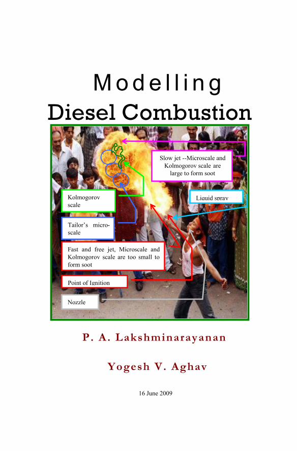
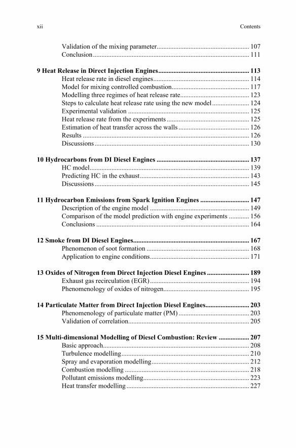
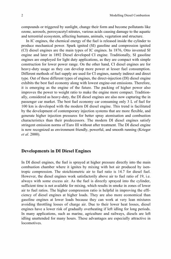
Nozzle
Tailor’s micro-scale
Kolmogorov scale
Fast and free jet, Microscale and Kolmogorov scale are too small to form soot
Slow jet --Microscale and Kolmogorov scale are
large to form soot
Point of Ignition
Liquid spray
16 June 2009
vii
Acknowledgments Our work at the Indian Institutes of Technology, Madras and Delhi and at
Loughborough University, and later at the industrial R&Ds of Ashok Leyland, Ltd. and Kirloskar Oil Engines, Ltd. for the last 4 decades forms the basis of the phenomenological models presented in the book. We are grateful to these great institutions for the constant encouragement and guidance we received. We express our thanks to FEV, India for their kind support during the preparation of the book.
The book is complete only with the last two chapters on the reviews and applications of modern methods of simulating diesel engines by Dr. Yu Shi and Prof. Dr. Rolf Reitz of Engine Research Centre at the University of Wisconsin, Madison. They acceded to our request spontaneously and gracefully to provide the material. We express our profound gratitude to them for showing magnanimity.
We thank our Professors Dr. B.S. Murthy, Dr. J.C. Dent, Dr. P.A. Janakiraman,
While writing the book, we heavily leaned on various research work carried out by us with our co-authors of papers published in many learned journals. We are indebted to them.
We thank Mr. R. Seshsayee, Ashok Leyland and Mr. R.R. Deshpande, Kirloskar Oil Engines, Ltd. for encouraging us to write this book.
We thank the Society of Automotive Engineers (SAE), American Society of Mechanical Engineers (ASME) and Institute of Mechanical Engineers, London (IMechE) for allowing us to use the figures and other material published by us in their learned journals. We thank the publishers Springer for giving us a chance to write this book.
We are thankful to our families for their support and understanding throughout
the research work and the preparation of the book.
P. A. Lakshminarayanan Yogesh V. Aghav June 16, 2009
Dr. M.K. Gajendra Babu and Dr. U.P. Nagpurkar, Dr. M.N. Kumar, Dr. Rainer Thiele, Mr. P.G. Bhat, and Mr. A.D. Dani for decisively influencing our formative years and subsequent research.

ix
Preface
Phenomenology of Diesel Combustion and Modeling Diesel is the most efficient combustion engine today and it plays an important role in transport of goods and passengers on land and on high seas. The emissions must be controlled as stipulated by the society without sacrificing the legendary fuel economy of the diesel engines. These important drivers caused innovations in diesel engineering like re-entrant combustion chambers in the piston, lower swirl support and high pressure injection, in turn reducing the ignition delay and hence the nitric oxides. The limits on emissions are being continually reduced. There-fore, the required accuracy of the models to predict the emissions and efficiency of the engines is high. The phenomenological combustion models based on physical and chemical description of the processes in the engine are practical to describe diesel engine combustion and to carry out parametric studies. This is because the injection process, which can be relatively well predicted, has the dominant effect on mixture formation and subsequent course of combustion. The need for improving these models by incorporating new developments in engine designs is explained in Chapter 2. With “model based control programs” used in the Electronic Control Units of the engines, phenomenological models are assuming more importance now because the detailed CFD based models are too slow to be handled by the Electronic Control Units.
Experimental work is necessary to develop the basic understanding of the proc-esses. Chapter 3 describes the experimental set up of the bomb for interferometry and real engine studies for validation of the phenomenological models. This chapter also includes the details of the measurement techniques for obtaining the experi-mental data needed for validating the phenomenology. Empirical relations have been obtained in Chapter 4 to describe the axial and radial variations of fuel con-centration in the vaporising and burning sprays, and to evaluate penetration and air entrainment of the free and wall jet regions. The movement of the ‘tail’ of the spray in the post injection period has been studied. These equations form the basis for building the phenomenological models of ignition delay, emissions and heat release rate in subsequent chapters.
The norms for NOx and HC emissions are so tight that prediction of ignition delay has become necessary. In Chapter 5, phenomenological calculations of the cooling of spray surface have shown that the physical parameters and fuel type influence the temperature of the mixture of air and the fuel vapour throughout its life up to the end of ignition delay. A model is proposed in Chapter 6 to predict rapid convective heat transfer between spray and wall by extending the analogy adopted by Woschni.
The rate of heat release in an indirect injection engine is modelled on the lines of its observed rate in a direct injection engine. The diffusion combustion is modeled as proportional to the available fuel and rate of air entrainment in Chapter 7. Chapter 8 introduces the concept of air useful for combustion. The ratio of
x Preface
momentum of the useful air to the total momentum of injected fuel near TDC at the end of ignition delay period is found to bear a universal relationship with the indicated efficiency and dry soot emissions in case of combustion chambers sup-ported by air swirl. In Chapter 9, the combustion rate is precisely described using the concept developed in Chapter 7 by relating the fuel air mixing rate to the turbulent energy created at the exit of the nozzle as a function of the injection velocity and by considering the dissipation of energy in free air and along the wall. The absence of adjustable constants distinguishes the model from the other zero-dimensional or pseudo multi-dimensional models.
Hydrocarbon (HC) emissions from direct injection diesel engines are mainly due to fuel injected and mixed beyond lean combustion limit during ignition delay and fuel effusing from the nozzle sac at low pressure. The concept has been developed in Chapter 10 to provide an elegant model to predict the HC emissions. To contrast the phenomenon of HC formation in a Diesel and in a spark ignition engine, Chapter 11 is included. The absorption and desorption of fuel by cylinder lubricating oil films has been modelled using principles of mass transfer.
A new model for smoke explained in Chapter 12 characterizes the smoke emit-ted at higher loads from the wall spray formed after impingement. Smoke has been treated by ignoring the fast chemistry, as the slow physical mixing seems to be controlling. A new phenomenological model for NOx emission is developed based on mixing controlled combustion incorporating localized wall heat transfer in Chapter 13. Based on the smoke formation and oil consumption, an estimate of the particulate matter is made in Chapter 14.
Chapter 15 and 16 on the modern methods of simulating diesel engines are con-tributed by Dr. Yu Shi and Prof. Dr. Rolf Reitz of Engine Research Centre at the University of Wisconsin, Madison. Chapter 15 reviews the basic approach of multi- dimensional CFD modelling of diesel combustion, and focusing on the advanced turbulence and combustion models. Recent efforts for reducing the computational expense of multi-dimensional CFD modelling are also discussed. CFD tools reveal details about invisible or technically difficult or costly in-cylinder processes of diesel combustion, so that guidance can be provided to improve engine designs in terms of emissions reduction and fuel economy; innovative combustion concepts can be evaluated numerically prior to experimental tests to reduce the number of investigated parameters and thus costs; important design parameters can be dis-covered by modelling engines of different sizes to establish engine size-scaling relationships and thus non-dimensionalizing engine designs; by integration with optimization methodologies, CFD tools can also directly impact the design of optimum engine systems, such as piston geometry and injection parameters. Each of these aspects is described by relevant case studies in Chapter 16.
xi
Contents Acknowledgments.................................................................................................vii
Preface .................................................................................................................... ix Phenomenology of diesel combustion and modeling........................................ ix
1 Introduction ......................................................................................................... 1 Role of internal combustion engines ......................................................... 1 Developments in DI diesel engines ........................................................... 2
2 Phenomenology of Diesel Combustion and Modelling .................................... 9 Combustion model................................................................................... 10 Emission models...................................................................................... 14 Theme of the book................................................................................... 17
3 Experiments ....................................................................................................... 23 Studies in a bomb .................................................................................... 23 Real engine studies .................................................................................. 29
4 Turbulent Structure of the Diesel Spray......................................................... 39 Vaporising spray...................................................................................... 39 Combusting sprays .................................................................................. 49 Summary of the model for vapourising and combusting sprays ............. 53 Modern view of the vaporising and burning spray.................................. 55
5 Ignition Delay in a Diesel Engine ..................................................................... 59 Definition and measurement of ignition delay ........................................ 60 Classical model for ignition delay and its extension to other fuels......... 61 Phenomenological model of ignition delay............................................. 63
6 Heat Transfer..................................................................................................... 79
7 Heat Release in Indirect Injection Engines..................................................... 83 Description of the phenomenological model........................................... 84 Experimental technique ........................................................................... 90 Results and discussions ........................................................................... 91 Conclusions ............................................................................................. 94
8 Mixing Correlations for Smoke and Fuel Consumption of Direct Injection Engines ............................................................................................... 99
Characteristic parameter for air fuel mixing in a cross flow................. 100
Modelling of combustion in DI diesel engines ......................................... 6
xii Contents
Validation of the mixing parameter....................................................... 107 Conclusion............................................................................................. 111
9 Heat Release in Direct Injection Engines...................................................... 113 Heat release rate in diesel engines......................................................... 114 Model for mixing controlled combustion.............................................. 117 Modelling three regimes of heat release rate......................................... 123 Steps to calculate heat release rate using the new model...................... 124 Experimental validation ........................................................................ 125 Heat release rate from the experiments ................................................. 125 Estimation of heat transfer across the walls .......................................... 126 Results ................................................................................................... 126 Discussions ............................................................................................ 130
10 Hydrocarbons from DI Diesel Engines ....................................................... 137 HC model............................................................................................... 139 Predicting HC in the exhaust................................................................. 143 Discussions ............................................................................................ 145
11 Hydrocarbon Emissions from Spark Ignition Engines ............................. 147 Description of the engine model ........................................................... 149 Comparison of the model prediction with engine experiments ............ 156 Conclusions ........................................................................................... 164
12 Smoke from DI Diesel Engines..................................................................... 167 Phenomenon of soot formation ............................................................. 168 Application to engine conditions........................................................... 171
13 Oxides of Nitrogen from Direct Injection Diesel Engines ......................... 189 Exhaust gas recirculation (EGR)........................................................... 194 Phenomenology of oxides of nitrogen................................................... 195
14 Particulate Matter from Direct Injection Diesel Engines.......................... 203 Phenomenology of particulate matter (PM) .......................................... 203 Validation of correlation........................................................................ 205
15 Multi-dimensional Modelling of Diesel Combustion: Review .................. 207 Basic approach....................................................................................... 208 Turbulence modelling............................................................................ 210 Spray and evaporation modelling.......................................................... 212 Combustion modelling .......................................................................... 218 Pollutant emissions modelling............................................................... 223 Heat transfer modelling ......................................................................... 227
xiii
Efficient multi-dimensional simulation of diesel engine combustion with detailed chemistry ..................................................................... 229
CFD codes for engine simulation .......................................................... 238 Future and challenge.............................................................................. 241
16 Multi-dimensional Modelling of Diesel Combustion: Applications ......... 247 Case studies ........................................................................................... 248
Appendices .......................................................................................................... 283 Appendix I: Estimation of products of combustion from the
interferogram..................................................................................... 283 Appendix II: Estimation of concentration of fuel vapour in the
vapourising and combusting spray from the interferogram.............. 284 Appendix III: Estimation of mass and heat transfer functions.............. 285 Appendix IV: Vapour pressure of diesel and fuels A & B and B* ....... 285 Appendix V: Calculation of tangential velocity of air in the
piston cavity from the inlet swirl number ......................................... 286 Appendix VI: Momentum of useful air of the three different
combustion cavities described in Kuo et al. (1988).......................... 286 Appendix VII: Momentum of useful air for engines A8, B8,
C8 and D8 ......................................................................................... 287 Appendix VIII: Estimation of spray properties and impingement
parameters ......................................................................................... 288 Appendix IX: Calculation of fuel injection rate .................................... 290 Appendix X: Influence of nozzle features............................................. 291 Appendix XI: Henry’s constant Hc for fuel (n-octane) in oil ............... 292 Appendix XII: Evaluation of gF* and gG*............................................. 293 Appendix XIII: In-cylinder oxidation of HC......................................... 294 Appendix XIV: Estimation of wall surface temperature....................... 297 Appendix XV: Experimental data on HC emissions from DI diesel
engines............................................................................................... 298
Index .................................................................................................................... 301
Contents
1 Introduction
Abstract The Internal Combustion (IC) engines play a dominant role in the fields of transportation of goods and passengers, agricultural and industry. They develop power by consuming precious fossil fuels and cause pollution. Among different types of engines, the direct-injection (DI) diesel engine exhibits the best fuel economy along with lowest engine-out emissions. Efforts have been put to improve exhaust emissions and fuel economy continuously. The complex task of improving IC engines, which have reached a higher degree of sophistication, can be achieved by combination of advanced experiments and computational studies. Modern methods of experimental investigations are being developed to provide more insight. The modelling of combustion engine processes is useful to carry out extensive parametric studies, rather than hardware development and experimenta-tion. Depending on the various possible applications, different types of models for engine combustion processes have been developed. Therefore, theoretical and applied understanding of the engine processes is also developing at faster rate.
Role of Internal Combustion Engines
Rapid Increase in pollution levels, escalation of fuel prices, and depletion of hydrocarbon reserves of the world have forced the engineers to look for appropriate technology and alternative fuels to cater to the ever-increasing demands of energy. The Internal Combustion (IC) engines form an indispensable part of industrial growth. IC engines play a dominant role in the fields of propulsion, power and energy. They also contribute in our modernized agricultural sector and transporta-tion of goods and passengers. It is impossible to do without the IC engines and hence means must be sought to improve the designs.
It has been estimated that the present fossil fuel demand is expected to double between now and 2050. At present, about two-thirds of world energy demand is met by fluid fossil fuels because of their availability and convenience of use in existing design of several prime movers such as internal combustion engines. In future, the energy scenario is likely to be several times worse than the two oil crises of 1970s. The second predicament involving the fossil fuels is the environmental damage caused by combustion of fossil fuels. Technologies for fossil fuel extraction, transportation, processing and particularly their combustion have harmful impacts on the environment. The fossil fuels which constitute carbon and hydrogen in addition to traces of sulphur and quality enhancer additives like oxygenates produce various gases, soot, ash and other organic compounds during combustion and when released into atmosphere cause degradation of air quality (Walsh 2000, Fiaz and Sturm 2000). These pollutants when mixed with water and other atmospheric
P.A. Lakshminarayanan and Y.V. Aghav, Modelling Diesel Combustion, 1Mechanical Engineering Series, DOI 10.1007/978-90-481-3885-2_1, © Springer Science+Business Media B.V. 2010
2 Modelling Diesel Combustion
compounds or triggered by sunlight, change their form and become pollutants like ozone, aerosols, peroxyacetyl nitrates, various acids causing damage to the aquatic and terrestrial ecosystem, affecting humans, animals, vegetation and structure.
In IC engines, the chemical energy of the fuel is released inside the cylinder to produce mechanical power. Spark ignited (SI) gasoline and compression ignited (CI) diesel engines are the main types of IC engines. In 1876, Otto invented SI engine and later in 1892 Diesel developed CI engine. Traditionally, SI gasoline engines are employed for light duty applications, as they are compact with simple construction for lower power range. On the other hand, CI diesel engines are for heavy-duty usage as they can develop more power at lesser fuel consumption. Different methods of fuel supply are used for CI engines, namely indirect and direct type. Out of these different types of engines, the direct-injection (DI) diesel engine exhibits the best fuel economy along with lowest engine-out emissions. Therefore, it is emerging as the engine of the future. The packing of higher power also improves the power to weight ratio to make the engine more compact. Tradition-ally, considered as heavy-duty, the DI diesel engines are also now capturing the in passenger car market. The best fuel economy car consuming only 3 L of fuel for 100 km is developed with the modern DI diesel engine. This trend is facilitated by the development of contemporary injection systems that are more flexible, and generate higher injection pressures for better spray atomisation and combustion characteristics than their predecessors. The modern DI diesel engines satisfy stringent emission norms of Euro III without after treatment. The DI diesel engine is now recognized as environment friendly, powerful, and smooth running (Krieger et al. 2000).
Developments in DI Diesel Engines
In DI diesel engines, the fuel is sprayed at higher pressure directly into the main combustion chamber where it ignites by mixing with hot air produced by isen-tropic compression. The stoichiometric air to fuel ratio is 14.7 for diesel fuel. However, the diesel engines work satisfactorily above air to fuel ratio of 19, i.e. always with some excess air. As the fuel is directly sprayed into the cylinder, sufficient time is not available for mixing, which results in smoke in zones of lower air to fuel ratios. The higher compression ratio is helpful in improving the effi-ciency of diesel engines at higher loads. They are also more economical than gasoline engines at lower loads because they can work at very lean mixtures avoiding throttling losses of charge air. Due to their lower heat losses, diesel engines have a lower risk of gradually overheating if left idling for long periods. In many applications, such as marine, agriculture and railways, diesels are left idling unattended for many hours. These advantages are especially attractive in locomotives.

1 Introduction 3
A naturally aspirated diesel engine produces less power density i.e., power in a given volume, compared to gasoline engines. The power of the diesel engine is always limited by the air available. Therefore, they are often turbocharged to improve power density. The turbocharged versions can produce more power than petrol engines limited by mechanical capability. The diesel engines do not face knocking problem. A turbocharger consists of a turbine and a compressor linked by a shared axle. The turbine inlet receives exhaust gases from the engine exhaust manifold causing the turbine wheel to rotate. This rotation drives the compressor, compressing ambient air and delivering it to the intake of the engine; this allows more fuel to burn in the cylinder. At higher boost, the benefit of more air mass diminishes as the density drops substantially. Inter-cooling by using atmospheric air or engine jacket water helps to recover the density by bringing down the tem-perature of the charge. The charge air is not throttled in diesel engines; therefore, a governor is used to control fuel supply quantity. A sophisticated fuel supply system consisting of pumping unit, multi-hole injector and governor are employed in DI diesel engines to inject the correct amount of fuel at the required time under favourable conditions for combustion.
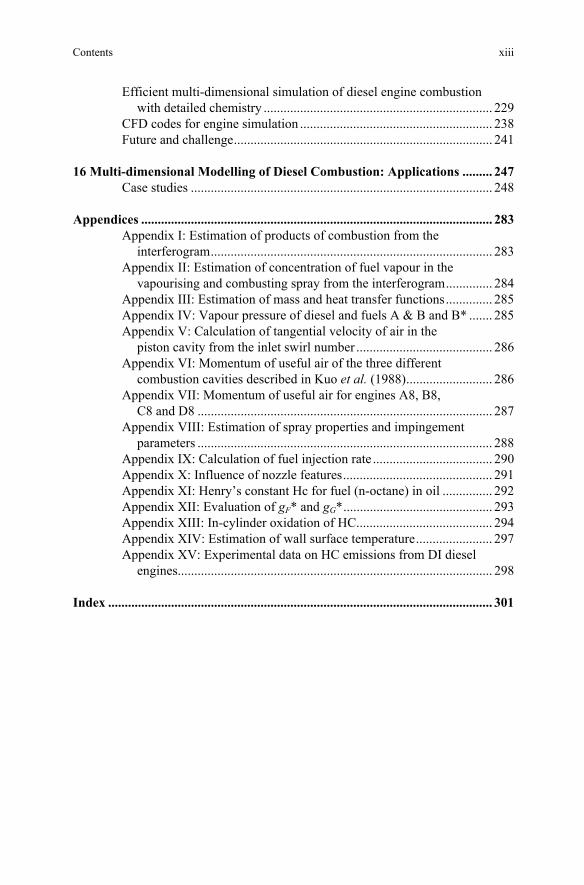
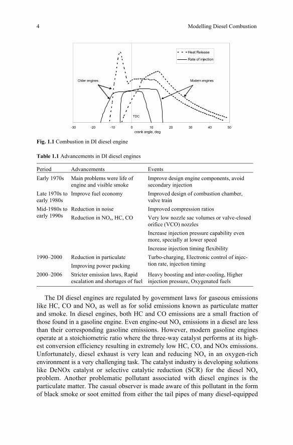
Early DI diesel engines operated at relatively low compression ratios and low injection pressures. Hence, they demanded very advanced injection timings in commensurate with the large ignition delay. During the ignition delay period at the beginning of combustion, up to about 20% of the injected fuel is prepared to stoichiometric proportion. Due to high flame speed, the prepared mixture burns at high temperature to produce nitrogen oxides and explosive noise characteristic of a diesel engine (Fig. 1.1). This period of combustion is said to be premixed phase governed by chemical kinetics. On the other hand, the rest of the fuel burns as and when the mixture is prepared because the delay is absent with hot gases and radicals available in the vicinity, remnant of the fuel burnt earlier. This second part is called diffusive phase and the rate of combustion of the majority of fuel is controlled by the physical mixing processes in the spray. The third or the last stage corresponds to the tail of heat release diagram in which a small but distinguishable rate of heat release persists well into the expansion stroke (Heywood 1988). Such a design was the result of the available technology and lack of norms for noise and emissions.
During last 50 years, the design of DI engines has undergone a sea change because of social and economical aspects (Bosch 2000). With the advent of new emission norms, reduction in ignition delay held the key to solve twin problems of NOx emission and noise. Higher temperature at the beginning of injection by increased compression ratio reduced the delay period and subsequent premixed combustion phase substantially. Higher injection pressures and turbulence were introduced to improve the mixing rate and hence to maintain the combustion duration within a reasonable limit, in spite of the loss of fast burning premixed combustion process. User demands of improving fuel economy and legal require-ment of reduction in emissions are driving the engine development persistently. The advancements in design are summarized in Table 1.1.
4 Modelling Diesel Combustion
Fig. 1.1 Combustion in DI diesel engine
Table 1.1 Advancements in DI diesel engines Period Advancements Events Early 1970s Main problems were life of
engine and visible smoke Improve design engine components, avoid secondary injection
Late 1970s to early 1980s
Improve fuel economy Improved design of combustion chamber, valve train
Mid-1980s to early 1990s
Reduction in noise Reduction in NOx, HC, CO
Improved compression ratios Very low nozzle sac volumes or valve-closed orifice (VCO) nozzles Increase injection pressure capability even more, specially at lower speed Increase injection timing flexibility
1990–2000
Reduction in particulate Improving power packing
Turbo-charging, Electronic control of injec-tion rate, injection timing
2000–2006
Stricter emission laws, Rapid escalation and shortages of fuel
Heavy boosting and inter-cooling, Higher injection pressure, Oxygenated fuels
The DI diesel engines are regulated by government laws for gaseous emissions
like HC, CO and NOx as well as for solid emissions known as particulate matter and smoke. In diesel engines, both HC and CO emissions are a small fraction of those found in a gasoline engine. Even engine-out NOx emissions in a diesel are less than their corresponding gasoline emissions. However, modern gasoline engines operate at a stoichiometric ratio where the three-way catalyst performs at its high-est conversion efficiency resulting in extremely low HC, CO, and NOx emissions. Unfortunately, diesel exhaust is very lean and reducing NOx in an oxygen-rich environment is a very challenging task. The catalyst industry is developing solutions like DeNOx catalyst or selective catalytic reduction (SCR) for the diesel NOx problem. Another problematic pollutant associated with diesel engines is the particulate matter. The casual observer is made aware of this pollutant in the form of black smoke or soot emitted from either the tail pipes of many diesel-equipped
-30 -20 -10 0 10 20 30 40 50crank angle, deg
Heat Release
Rate of injection
Modern enginesOlder engines
TDC
1 Introduction 5
passenger cars or the stacks of diesel-powered heavy-duty vehicles. Emission of soot is also accompanied with other matter suspended in the exhaust, such as: unburned lube oil, unburned fuel, trace metals, and sulphur by-products. Emission of soot in particulate matter results from the nature of the heterogeneous combustion process or diffusion type combustion that is prevalent in diesel engines. Preparation of fuel and air mixture in modern diesel engines has greatly reduced this problem. The development of diesel particulate filters promises to eliminate it altogether.
There are a number of serious reasons for considering bio-fuels like vegetable oil based bio-diesel, alcohols, as alternatives for petroleum based diesel fuel, e.g. expected growth of prices of fossil liquid fuels in the near future and gradual exhaustion of crude oil sources in the next 80–100 years. Governments of many countries have started thinking that bio-fuels will provide boost to agricultural industry. In addition, the oxygenated fuels have attracted increasing attention in engine development owing to its excellent combustion characteristics in reducing emissions (Miyamoto et al. 1998, Xiao et al. 2000). Therefore, oxygenated fuels would find way as a supplement and substitute for diesel fuels for regular usage.
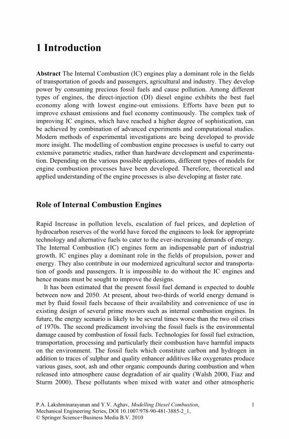
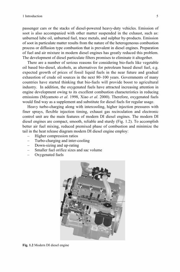
Heavy turbo-charging along with intercooling, higher injection pressures with finer sprays, flexible injection timing, exhaust gas recirculation and electronic control unit are the main features of modern DI diesel engines. The modern DI diesel engines are compact, smooth, reliable and sturdy (Fig. 1.2). To accomplish better air fuel mixing, reduced premixed phase of combustion and minimize the tail in the heat release diagram modern DI diesel engine employ:
– Higher compression ratios – Turbo-charging and inter-cooling – Down-sizing and up-rating – Smaller fuel orifice sizes and sac volume – Oxygenated fuels
Fig. 1.2 Modern DI diesel engine
6 Modelling Diesel Combustion
Modelling of Combustion in DI Diesel Engines
The complex task of improving IC engines, which have reached a higher degree of sophistication, can be achieved by combination of advanced experiments and computational studies. Despite the quantitative uncertainties of numerical simula-tions, which are often greater than those of experiments are, the modelling of combustion engine processes has some significant advantages that make its utiliza-tion in engine development a necessity. In this regard, it is obvious that numerical simulations are especially suited to carry out extensive parametric studies, since they are more effective than the alternative construction and investigation of numerous prototypes (Stiesch 2003).
The advantages of engine modelling are: (a) parametric studies of each variable can be done, (b) wide range of boundary conditions can be analysed, (c) separation of each sub-process from other, (d) detailed information is available as output, (e) effective in terms of time and cost.
Depending on the various possible applications, different types of models for engine combustion processes have been developed. Three different model categories are typically distinguished. In an order of increasing complexity and increasing requirements with respect to computer power, these are zero-dimensional thermodynamic models, quasi-dimensional phenomenological models and multi-dimensional computational fluid dynamics (CFD) models.
In thermodynamic models, the heat release by combustion cannot be easily derived by a detailed modelling of physical and chemical sub-processes, because these processes are strongly affected by the distribution of unresolved spatial temperature and composition. Because the combustion chamber is taken as zero-dimensional, it is mandatory to model the heat release rate by empirical sub-models using simple mathematical equations. On the other hand, the multidimensional CFD models are based on locally resolved solution of conservation of mass, energy, momentum, and include detailed sub-models for spray and combustion phenomena. With these models, the gas flow patterns can be predicted best and prediction of fuel spray are less complete and combustion calculations present considerable difficulties. The CFD models are of immense use to appreciate the inner mechanism of diesel sprays, but are very difficult to comprehend during the complete simula-tion of a diesel engine. Therefore, there is a need for a third category of model that allows to execute efficient, fast and economic preliminary calculations of heat release models and exhaust emissions as a function of important engine parameters like injection pressure, injection timing, swirl ratio and boost pressure. These models based on physical and chemical sub-models, for local processes like spray formation, air fuel mixing, ignition and combustion including emission formation are termed as phenomenological models. Therefore, these models are more com-prehensive compared to thermodynamic models and consume less computational resources compared to CFD models. It should be noted that phenomenological models are the most practical to describe diesel engine combustion (Stiesch 2003).
1 Introduction 7
This is because the injection process, which can be relatively well predicted with the phenomenological approach, has the dominant effect on mixture formation and subsequent course of combustion. Therefore, these models are widely used as predictive tools for carrying out parametric studies during engine development.
Many experimental investigations are also being carried out to provide better insight of the combustion process happening under engine environment. More recently, the development of laser-based diagnostics has provided a means for making detailed insitu measurements of the processes occurring inside a reacting diesel fuel jet. These diagnostics allow specific species within the reacting jet to be measured at multiple points simultaneously with high spatial and temporal resolution.
Even though the IC engine was invented a century ago, its development is continuing, as new technology is available and new demands are arising. Although the DI diesel engine is a better choice among different types of IC engines as a prime mover considering fuel economy and exhaust emissions, efforts are being put to improve them further to meet future stringent demands of fuel economy and pollution. Alternative technologies and fuels are being implemented in these engines. Therefore, theoretical and applied understanding of the engine processes is also developing at faster rate.
References Bosch Automotive Handbook. Bosch, 5th Edition, 2000 Fiaz A, Sturm PJ (2000) New Directions, Road Traffic in Developing Countries, Journal of
Atmospheric Environment 2000; 34: 4745–4746 Heywood JB (1988) A text book on Internal Combustion engine fundamentals. McGraw-Hill
International edition Krieger K, Hummel HG and Naik LM (2000) Diesel Fuel Injection Technology: An essential
contribution towards an environment friendly powerful diesel engine. SAE 2000-01-1429 Miyamoto N, Ogawa H, Nurun NM, Obata K, Arimes T (1998) Smokeless, low NOx, high
thermal efficiency and low noise diesel combustion with oxygenated agents as main fuel. SAE 980506
Stiesch G (2003) Modelling engine spray and combustion processes, Springer Walsh MP (2000) Global Trends in motor Vehicle Pollution Control, Accomplishments to Date
and Challenges for New Millennium. Paper No. F2000PH02, Proceedings of FISITA-2000, Seoul, Korea
Xiao Z, Ladommatos N, Zhao H (2000) The effect of aromatic hydrocarbon and oxygenates on diesel engine emissions. IMechE 214, Part D

P.A. Lakshminarayanan and Y.V. Aghav, Modelling Diesel Combustion, 9 Mechanical Engineering Series, DOI 10.1007/978-90-481-3885-2_2, © Springer Science+Business Media B.V. 2010
2 Phenomenology of Diesel Combustion and Modelling
Abstract Diesel is the most efficient combustion engine today and it plays an important role in transport of goods and passengers on road and on high seas. It is expected that the diesel engine will be active for another 100 years as increasingly economical sources are found with the increase in oil prices offering incentive to the explorers. The emissions must be controlled as demanded by the society with-out sacrificing the legendary fuel economy of the diesel engines. These important drivers caused innovations in diesel engineering like re-entrant combustion cham-bers in the piston, lower swirl support and high pressure injection, in turn reducing the ignition delay and hence the Nitric Oxides (NOx). From 16 g/kWh in 1988, the limit on NOx is reduced today to as low as 2.0 and PM limit is reduced from 0.8 g/kWh to 0.02. These limits are being continually reduced. Therefore, the required accuracy of the models to predict PM, NOx and efficiency of the engines is high. The phenomenological combustion models are practical to describe diesel engine combustion and to carry out parametric studies. This is because the injection proc-ess, which can be relatively well predicted with the phenomenological approach, has the dominant effect on mixture formation and subsequent course of combus-tion. The need for improving these models was also established by incorporating developments happening in engine designs. A phenomenological model consisting of sub-models for combustion and emissions are proposed in detail in this chapter. With more and more “model based control programs” used in the ECU controlling the engines, phenomenological models are assuming importance now. The full CFD based models though give detailed insight into the combustion phenomena and guide the design engineer, they are too slow to be handled by the ECU’s or for laying out the engine design. Therefore, phenomenological models have a bright future hand in hand with the sophisticated models. The diesel combustion is mod-elled by studying the structure of the spray, ignition delay, heat transfer, air-fuel mixing and heat release. These contribute to smoke, NOx and engine performance.
The Phenomenological Combustion Models are very practical to describe diesel combustion and to carry out parametric studies. This is because the injection proc-ess. The models are improved by incorporating new developments in engine designs.
The combustion in modern DI diesel engines is mainly divided in two phases: (a) a small ignition delay event in which pre-flame activities take place followed by (b) main heat release event in which actual combustion happens. These events are modelled differently considering prominent role of chemical kinetics during ignition and physical mixing rate during heat release. This approach is described
10 Modelling Diesel Combustion
in detail in the following sections. This chapter summarizes different types of models along with description of popular models.
Combustion Model
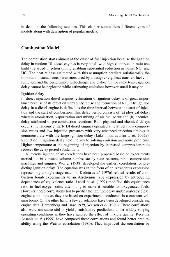
The combustion starts almost at the onset of fuel injection because the ignition delay in modern DI diesel engines is very small with high compression ratio and highly retarded injection timing enabling substantial reduction in noise, NOx and HC. The heat release estimated with this assumption predicts satisfactorily the important instantaneous parameters used by a designer e.g. heat transfer, fuel con-sumption, and the performance turbocharger and piston. On the same tenor, ignition delay cannot be neglected while estimating emissions however small it may be.
Ignition delay In direct injection diesel engines, estimation of ignition delay is of great impor-tance because of its effect on startability, noise and formation of NOx. The ignition delay in a diesel engine is defined as the time interval between the start of injec-tion and the start of combustion. This delay period consists of (a) physical delay, wherein atomisation, vaporization and mixing of air fuel occur and (b) chemical delay attributed to pre-combustion reactions. Both physical and chemical delays occur simultaneously. Early DI diesel engines operated at relatively low compres-sion ratios and low injection pressures with very advanced injection timings in commensurate with the large ignition delay (Lakshminarayanan et al. 2002a). Reduction in ignition delay held the key to solving emission and noise problems. Higher temperature at the beginning of injection by increased compression-ratio reduces the delay period substantially.
Numerous ignition delay correlations have been proposed based on experiments carried out in constant volume bombs, steady state reactors, rapid compression machines and engines. Wolfer (1938) developed the earliest correlation for pre-dicting ignition delay. The equation was in the form of an Arrehenius expression representing a single stage reaction. Kadota et al. (1976) related results of com-bustion bomb experiments to an Arrehenius type expression by introducing dependence of equivalence ratio. Lahiri et al. (1997) modified this equivalence ratio to fuel-oxygen ratio, attempting to make it suitable for oxygenated fuels. However, these correlations fail to predict the ignition delay under unsteady diesel engine conditions as they are based on experiments conducted in a constant vol-ume bomb. On the other hand, a few correlations have been developed considering engine data (Hardenberg and Hase 1979, Watson et al. 1980). These correlations also were not successful in yields, satisfactory predictions under widely varying operating conditions as they have ignored the effect of mixture quality. Recently Assanis et al. (1999) have compared these correlations and found better predict-ability using the Watson correlation (1980). They improved the correlation by
2 Phenomenology of Diesel Combustion and Modelling 11
introducing the equivalence ratio and tuning the empirical constants. They postu-lated that the introduction of the dependency of ignition delay on overall equiva-lence ratio makes the correlation more dynamic.
The time taken for visible fire to appear in the pre-mixed zone of spray is a strong function of pressure and temperature of the ambient. In addition, the physi-cal properties such as Cetane number, viscosity of fuel, nozzle-hole size, injected quantity and injection pressure contribute to the delay phenomenon in diesel engines (Chandorkar et al. 1988).
Heat release The shaft work by a diesel engine is the sum of work on the piston by the pressure produced by the heat released by combustion and the losses due to pumping, heat transfer and friction. While the flow losses and friction work could be reasonably comprehended, the heat release is dependent on the complex turbulent mixing of fuel and air at high temperature after compression. The variety of combustion chambers and types of fuel injection equipments influence the heat release rate characteristically.
Models based on fluid dynamics These types of models are often called as multidimensional models due to their inherent ability to provide detailed geometric information on the flow field based on the solution of the governing equations. In the numerical calculations of react-ing flows, computer time and storage constraints severely restrict the complexity of the reaction mechanism that can be incorporated. They use simplified model for predicting combustion, which is mixing controlled and kinetically controlled. The choice between these two models is made by the ratio of the chemical reaction time to the turbulent mixing time. Several three-dimensional simulation models of injection, mixing and burning in diesel engines exist (Cartillieri and Johns 1983, Gosman et al. 1985) describing various phenomena in the engine and providing possibilities of understanding the inner mechanism of diesel sprays. However, the volume of computation in multi-dimensional models is too prohibitive to carry out many parametric studies. In addition, their sub-models require a thorough valida-tion with detailed experiments before employing them confidently in engine design work.
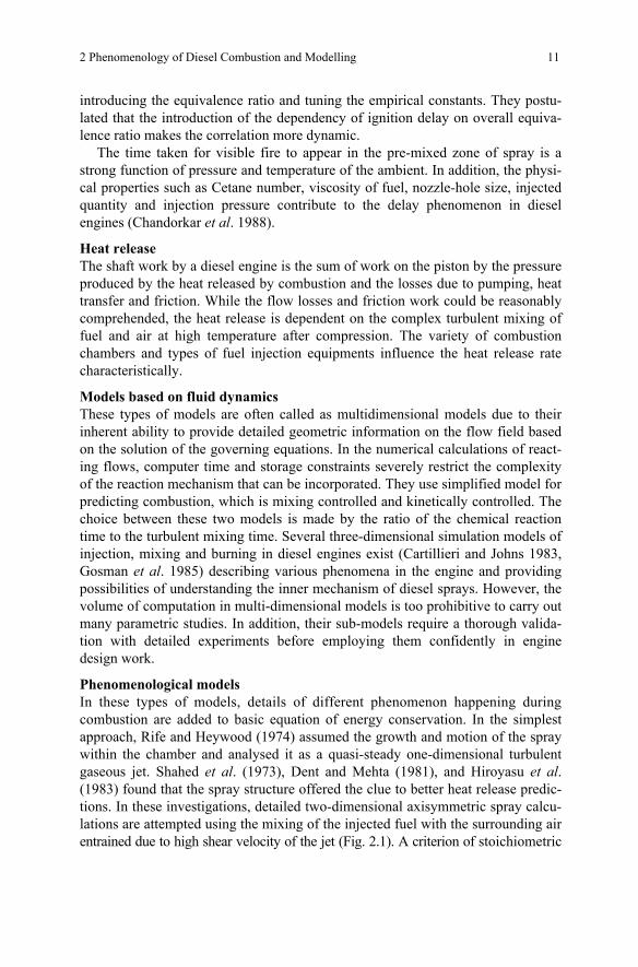
Phenomenological models In these types of models, details of different phenomenon happening during combustion are added to basic equation of energy conservation. In the simplest approach, Rife and Heywood (1974) assumed the growth and motion of the spray within the chamber and analysed it as a quasi-steady one-dimensional turbulent gaseous jet. Shahed et al. (1973), Dent and Mehta (1981), and Hiroyasu et al. (1983) found that the spray structure offered the clue to better heat release predic-tions. In these investigations, detailed two-dimensional axisymmetric spray calcu-lations are attempted using the mixing of the injected fuel with the surrounding air entrained due to high shear velocity of the jet (Fig. 2.1). A criterion of stoichiometric
12 Modelling Diesel Combustion
burning of the fuel in ignitable elements has been used in these models by spray-mixing approach.
Air zones
Rate of mixture preparation for burning
FuelInjection Rich core
Rate of air entrainment in each zone
Fig. 2.1 Multi zone spray model
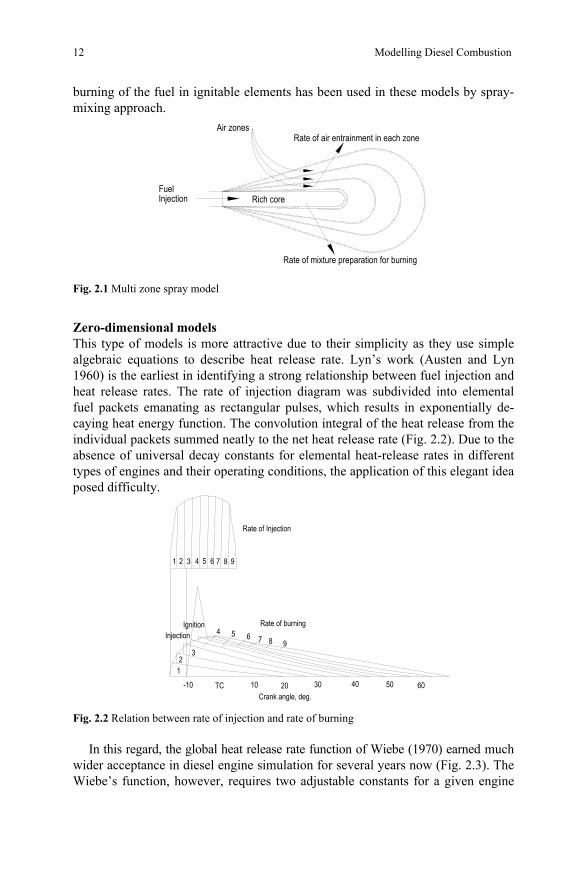
Zero-dimensional models This type of models is more attractive due to their simplicity as they use simple algebraic equations to describe heat release rate. Lyn’s work (Austen and Lyn 1960) is the earliest in identifying a strong relationship between fuel injection and heat release rates. The rate of injection diagram was subdivided into elemental fuel packets emanating as rectangular pulses, which results in exponentially de-caying heat energy function. The convolution integral of the heat release from the individual packets summed neatly to the net heat release rate (Fig. 2.2). Due to the absence of universal decay constants for elemental heat-release rates in different types of engines and their operating conditions, the application of this elegant idea posed difficulty.
1 2 3 4 5 6 7 8 9
InjectionIgnition Rate of burning
Rate of Injection
Crank angle, deg. -10 TC 10 20 30 40 50 60
12
3
4 5 6 7 8 9
Fig. 2.2 Relation between rate of injection and rate of burning
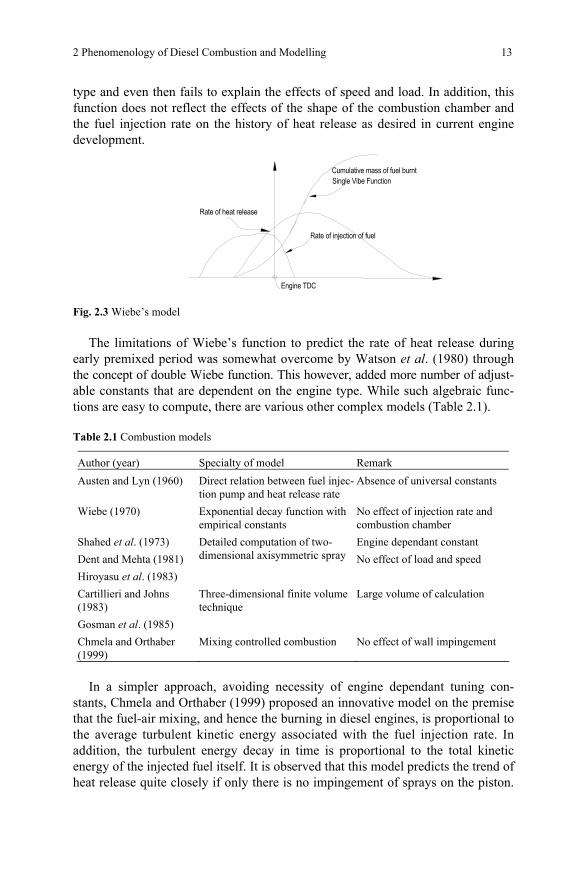
In this regard, the global heat release rate function of Wiebe (1970) earned much wider acceptance in diesel engine simulation for several years now (Fig. 2.3). The Wiebe’s function, however, requires two adjustable constants for a given engine
2 Phenomenology of Diesel Combustion and Modelling 13
type and even then fails to explain the effects of speed and load. In addition, this function does not reflect the effects of the shape of the combustion chamber and the fuel injection rate on the history of heat release as desired in current engine development.
Engine TDC
Rate of injection of fuel
Rate of heat release
Cumulative mass of fuel burntSingle Vibe Function
Fig. 2.3 Wiebe’s model
The limitations of Wiebe’s function to predict the rate of heat release during early premixed period was somewhat overcome by Watson et al. (1980) through the concept of double Wiebe function. This however, added more number of adjust-able constants that are dependent on the engine type. While such algebraic func-tions are easy to compute, there are various other complex models (Table 2.1).
Table 2.1 Combustion models
Author (year) Specialty of model Remark Austen and Lyn (1960) Direct relation between fuel injec-
tion pump and heat release rate Absence of universal constants
Wiebe (1970) Exponential decay function with empirical constants
No effect of injection rate and combustion chamber
Shahed et al. (1973) Dent and Mehta (1981) Hiroyasu et al. (1983)
Detailed computation of two-dimensional axisymmetric spray
Engine dependant constant No effect of load and speed
Cartillieri and Johns (1983) Gosman et al. (1985)
Three-dimensional finite volume technique
Large volume of calculation
Chmela and Orthaber (1999)
Mixing controlled combustion No effect of wall impingement
In a simpler approach, avoiding necessity of engine dependant tuning con-
stants, Chmela and Orthaber (1999) proposed an innovative model on the premise that the fuel-air mixing, and hence the burning in diesel engines, is proportional to the average turbulent kinetic energy associated with the fuel injection rate. In addition, the turbulent energy decay in time is proportional to the total kinetic energy of the injected fuel itself. It is observed that this model predicts the trend of heat release quite closely if only there is no impingement of sprays on the piston.
14 Modelling Diesel Combustion
A comparison of the predicted and the experimental results is not satisfactory in case of spray impinging on the wall. This situation arises in engines of capaci-ties less than 2 L per cylinder operating at more than half load, where majority of diesel engines belongs. Therefore, an attempt has been made in this book to enhance this model by encompassing the phenomena at the wall and the instanta-neous injection rate derived from the indicated performance of fuel injection equipment (Lakshminarayanan et al. 2002a).
Emission Models
DI diesel engines emit smoke, hydrocarbons, nitric oxides, carbon monoxide and particulate matter are mainly regulated. They are formed in different phases of combustion as described below.
Hydrocarbons The fuel leaned beyond flammability limits (Greeves et al. 1977), bulk quenching during expansion, fuel effusing from nozzle sac after completion of injection (Yu et al. 1980) are the most important reasons for Hydrocarbon (HC) emissions. A semi-empirical phenomenological model was successfully made for HC emissions considering the fuel injected and mixed beyond the lean combustion limit during ignition delay and fuel effusing from the nozzle sac at low pressure (Lakshmina-rayanan et al. 2002b). Exhaust gas recirculation (EGR), a well-accepted method of NOx reduction, alters ignition delay and HC emissions. The oxygen-enriched fuels that attract great attention worldwide owing to its excellent combustion character-istics, exhibit different behaviour especially in case of ignition delay and HC emissions.
Oxides of nitrogen Considering the heterogeneous nature of fuel-air mixture in diesel engines, NOx and particulate matter (PM) are important emissions. Continuous efforts are being made to minimize the quantities of these two pollutants from the diesel engine exhaust. Vioculescu and Borman (1978) carried out gas sampling from within the cylinder of a naturally aspirated direct injection (DI) diesel engine using a rapid acting sampling valve. This resulted in a plot showing time history of ratio of the average cylinder NOx concentration in the exhaust during the combustion process. Similar modelling and gas sampling studies have been done with indirect injection (IDI) diesel engines, which suggest that prechamber is the prominent location for formation of nitrogen oxides (Mansouri et al. 1982). Duggal et al. (1978) plotted the NO concentrations and equivalence ratios as a function of crank angle using a rapid-acing sampling valve at different locations within the prechamber of a swirl chamber IDI engine. There are a number of potential mechanisms responsible for NO in combustion processes. The relative importance of these different mechanisms is strongly affected by the temperature, fuel-air equivalence ratio, pressure, flame
2 Phenomenology of Diesel Combustion and Modelling 15
conditions, residence time and concentrations of key reacting species. Rapid NOx formation begins after the start of heat release. Shortly after the end of heat release, the period of rapid NOx formation ends because temperatures of the burned gas decrease due to mixing with cool bulk gas and expansion of the charge (Kitamura et al. 2005). Fuel-Air equivalence ratio is another important factor influencing NOx formation. As the equivalence ratio becomes leaner, NO and NOx decrease significantly as expected. NO2 however shows an opposite trend to that of NO that causes the NO2/NOx ratio to increase at leaner conditions. The NO2 peaks at an equivalence ratio near 0.25. Leaner equivalence ratio is indicative of lower loads and lower bulk gas temperatures that are conducive to the formation of NO2 (Pipho et al. 1991).
Advancing injection timing or increasing injection pressure improves combus-tion efficiency raises combustion temperature. In general, higher combustion tem-peratures lead to higher NOx formation (Henein and Patterson 1972). Addition of diluents to the engine intake air is considered as an effective mean to reduce the NO formation rate and hence the exhaust NOx levels. The effect is primarily one of reducing the peak flame temperature, which is the driving factor for NOx for-mation. Diluents such as N2, CO2 and exhaust gas were added to the intake air of direct injection (DI) engine to study their effect on NOx reduction (Challen and Baranescu 1999). Similar studies done in indirect injection (IDI) engine showed similar trends (Yu and Shahed 1981). Plee et al. (1981, 1983) established a corre-lation showing the effect of changes in intake air composition and temperature on NOx emissions.
NOx emissions comprise of NO and NO2. The NO2 is formed via NO molecule. Therefore, the modelling of NOx formation is most often reduced to studying the formation of NO. It is widely accepted that in diesel engines the major portion of NO is formed via thermal path (Ahmed and Plee 1983). Many multi-dimensional and multi-zone phenomenological models use extended Zeldovich mechanism (Heywood 1988). This mechanism was postulated by Zeldovich (1946) and improved by Lavoie et al. (1970). Khan et al. (1973) related FIE and engine operating conditions to NO formation and developed a method of calculation for emissions (Khan et al. 1973). They concluded that an increased rate of injection or increased air swirl reduces the amount of exhaust smoke and increases NOx.
All these models utilize empirical heat transfer correlation, which are mass averaged. During combustion, the heat loss is caused partly by convection from burned gases at high temperature and partly by radiation from soot particles formed during the diffusion flame. Due to the short distance between the nozzle and the combustion chamber wall under typical operating conditions, diesel fuel impinges on the wall in the form of liquid followed by fuel vapour and flame after onset of auto-ignition. The peak radiant heat flux is always less than 20% total heat flux confirming the dominant role of spray and flame interaction with piston bowl (Arcoumenis et al. 1998).
The contribution of convective mode of heat transfer is about 80% to total engine heat transfer (Heywood 1988, Stiesch 2003). However, it is known that in
16 Modelling Diesel Combustion
diesel engines radiative heat transfer may have a significant contribution in addi-tion to convective heat transfer. The radiative heat transfer in diesel engines is caused by both radiation of hot gases and by radiation of soot particles within the diffusion flame. It is agreed in the literature that the latter has a significantly greater impact on the radiative heat flux, and thus most heat transfer models concentrate on the radiation of soot only. It should be noted though, that a general difficulty in the evaluation of soot radiation exists in that the prediction of the soot concentra-tion itself is typically subject to significant uncertainties (Stiesch 2003). Therefore, the empirical heat transfer correlations focused mainly on convective mode.
The heat transfer coefficient has been derived by many researchers by assuming an analogy with a steady turbulent flow over a solid wall. The colour pyrometer and fast response thermocouples were employed for experimental investigations. Annand (1963) developed correlation for convective heat transfer but it was based on experiments conducted on only cylinder head. Probably, the most widely used approach in this category is the one suggested by Woschni (1967). Hohenberg (1979) improved the above correlation by using a length based on instantaneous cylinder volume and exponent of the temperature term. This approach gives an estimate of the surface-averaged heat transfer coefficient history in terms of the bulk gas temperature and a surface-averaged or total heat flux (Ikegami et al. 1986, Nishiwaki 1998). However, this approach cannot give the kind of informa-tion necessary to design modern engines. The empirical correlations underestimate to varying degrees the heat transfer during combustion. The investigations have revealed that during the combustion period the wall heat flux is substantial locally in space and time, due to the transient nature of the flame propagation. In particu-lar, during combustion the heat flux increases rapidly after impingement on the wall (Kleemann et al. 2001). The characteristics of injected spray and its interac-tion with the swirling air and the wall of the combustion chamber determine the efficiency and the exhaust emissions. In Chapter 14, a phenomenological model for NOx prediction is proposed based on spray combustion incorporating localised effect of heat transfer in wall spray and exhaust gas recirculation.
Smoke and particulate matter The characterization of diesel smoke has remained a challenge in engine develop-ment and modeling work. Effect of different parameters of combustion chamber and injection on soot and NOx emissions were investigated by De Risi et al. (1999, 2005). Kurtz and Foster (2004) identified critical time for mixing in diesel engine and its effect on emissions. Based on in-situ laser diagnostics, a conceptual model of burning jet was developed (John Dec 1997). Khan et al (1973) first presented a model for the prediction of soot related to engine operating condition. Hiroyasu et al. (1976) proposed a two-step semi empirical model and applied it to the multi-packet combustion model. Later on, the model was extended up to a simple three-dimensional model (Nishida K, Hiroyasu H 1989). Fusco et al. (1994) proposed that either pyrolysis of fuel could result in soot precursor radicals or growth species with possibilities of oxidation at intermediate stages. There is a principal mathematical problem in the modeling of the engine-out soot emissions by using
2 Phenomenology of Diesel Combustion and Modelling 17
formation and oxidation methodology (Stiesch G 2003). Since the soot mass in the exhaust is the very small difference between two nearly equal large quantities i.e. between formation and oxidation, a significant error will result if only a small deviation in either the production or the formation rate. Magnussen et al. (1976)
soot was formed and contained in the turbulent eddies within the flame. The burn up of the soot was related to the dissipation of turbulence. In this view, Dent’s work (1980) was unique. The importance of turbulent energy dissipation rate on smoke in quiescent chamber diesel engines was identified quantitatively. Recently, Dec and Tree (2001a, 2001b) investigated interactions of combusting fuel jet free in air and at the wall using laser diagnostics. They found that soot deposi-tion on the wall and blow-off are not the major contributors to engine-out soot emissions. In chapter 12, a model that clearly distinguishes the free jet and wall jet regimes of a diesel-engine spray and their turbulence structure is developed to explain the smoke.
Diesel particulates consist principally of carbonaceous material (soot from smoke) generated by combustion on which some organic compounds have become absorbed. Most of the particulate material results from incomplete combustion of fuel hydrocarbons; some is contributed by the lubricating oil (Heywood 1988). Diesel particulate matter is therefore a complex mixture of organic and inorganic compounds in solid and liquid phases (Johnson et al. 1994). The basic measure-ment of particulate matter is by its mass and it can be described as any exhaust com-ponents other than uncombined water that collects on a filter in a dilution tunnel at a temperature less than 53°C. In the standard procedure of measurement of mass emission, dilution tunnels are used to simulate the physical and chemical pro-cesses the particulate emissions undergo in the atmosphere. In the dilution tunnel, the raw exhaust gases are diluted with the ambient air to a temperature of 53°C or less and the sample stream from the diluted exhaust is filtered to remove the particulate matter. The mathematical modelling of particulate matter is always concentrated around soot because of its complex nature. Different studies have been carried out to establish contributions of soot, unburnt HC from fuel and lubricating oil (Cartillieri and Trittari 1984, Cartillieri and Wachter 1987, Cartillieri and Herzog 1988). Most of the PM correlations consider only soot to estimate particulate matter. Recently one phenomenological model is proposed for PM based on soot and unburnt HC from fuel (Tan et al. 2007). However, this model requires tuning of engine and load dependent constants. It does not account for SOF from lubricating oil and IOF from sulphates.
Theme of the Book
The literature survey highlighted some of the limitations of present phenomeno-logical models for application to modern engines. The available models require many engine-dependent empirical constants and consideration is given to neither
carried out experiments on steady state free diffusion flames and concluded that
18 Modelling Diesel Combustion
spray-wall interaction nor the effect of oxygenated fuels. The book presents the results of the research work based on comprehensive experimental work under-taken for improving phenomenological modelling of combustion in modern engines.
The highlights of the phenomenology of diesel combustion considered in the following chapters are as follows.
– Analysis of modern in-cylinder emission control technologies – Turbulence structure for engine sprays – Spray-wall interaction and its effect – Mixing controlled combustion – Localized heat transfer – Quasi one-dimensional approach to the heat release in DI engines – Consideration to fuel bound oxygen – Avoid engine dependent constants – Sub-model for prediction of combustion – Sub-models for important exhaust emissions
About 50 modern engines (Table 3.2) from 21 different engine families with widely varying features like bore-sizes, aspiration and cooling system are selected for experimental work. These engines meet current emission norms and are capa-ble of upgrading to next stage with minor changes. Observations pertaining to fuel injection, emissions and engine performance were collected simultaneously using experimental set up specially developed. Additional experiments were also carried out to study the effect of oxygenated fuels and exhaust gas recirculation on a few engines. The new models are thoroughly validated by using a large number of data collected from many experimental data. In addition, the results of new models are compared with 1-D engine cycle simulation tools like ‘AVL Boost (2005) which are being extensively used for engine development. The objectives of research work are:
– To improve understanding of ignition delay and mixing controlled com-bustion
– Develop turbulence structure for engine spray – Estimation of combustion cavity – spray interaction – Wall impingement of sprays causing loss of kinetic energy and intense
heat transfer – Effect of exhaust gas recirculation, EGR on combustion – Effect of fuel bound oxygen on combustion and emission – Effect of injection characteristics and nozzle features
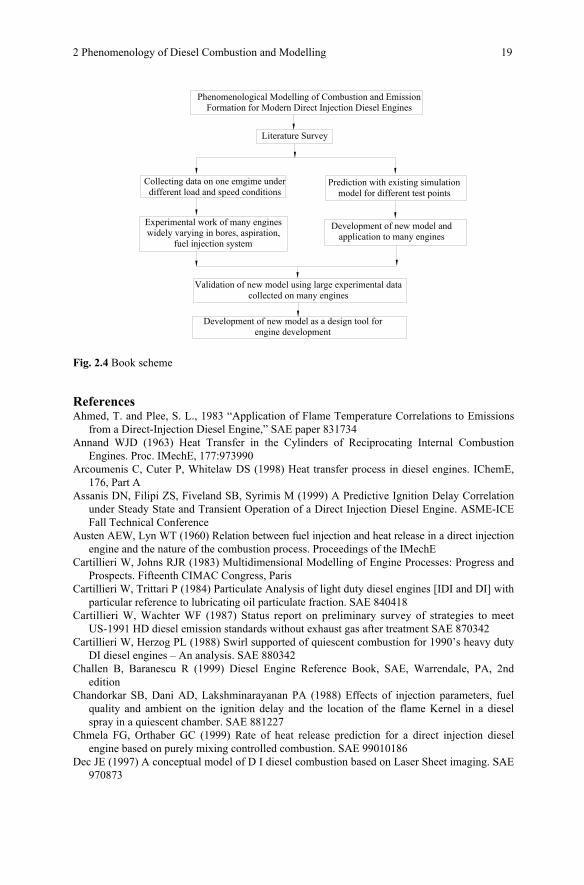
To meet above objectives, a research scheme was developed as shown sche-matically in the Fig. 2.4.
2 Phenomenology of Diesel Combustion and Modelling 19
Phenomenological Modelling of Combustion and Emission Formation for Modern Direct Injection Diesel Engines
Literature Survey
Collecting data on one emgime under different load and speed conditions
Experimental work of many engines widely varying in bores, aspiration,
fuel injection system
Validation of new model using large experimental data collected on many engines
Development of new model as a design tool for engine development
Prediction with existing simulation model for different test points
Development of new model and application to many engines
Fig. 2.4 Book scheme
References Ahmed, T. and Plee, S. L., 1983 “Application of Flame Temperature Correlations to Emissions
from a Direct-Injection Diesel Engine,” SAE paper 831734 Annand WJD (1963) Heat Transfer in the Cylinders of Reciprocating Internal Combustion
Engines. Proc. IMechE, 177:973990 Arcoumenis C, Cuter P, Whitelaw DS (1998) Heat transfer process in diesel engines. IChemE,
176, Part A Assanis DN, Filipi ZS, Fiveland SB, Syrimis M (1999) A Predictive Ignition Delay Correlation
under Steady State and Transient Operation of a Direct Injection Diesel Engine. ASME-ICE Fall Technical Conference
Austen AEW, Lyn WT (1960) Relation between fuel injection and heat release in a direct injection engine and the nature of the combustion process. Proceedings of the IMechE
Cartillieri W, Johns RJR (1983) Multidimensional Modelling of Engine Processes: Progress and Prospects. Fifteenth CIMAC Congress, Paris
Cartillieri W, Trittari P (1984) Particulate Analysis of light duty diesel engines [IDI and DI] with particular reference to lubricating oil particulate fraction. SAE 840418
Cartillieri W, Wachter WF (1987) Status report on preliminary survey of strategies to meet US-1991 HD diesel emission standards without exhaust gas after treatment SAE 870342
Cartillieri W, Herzog PL (1988) Swirl supported of quiescent combustion for 1990’s heavy duty DI diesel engines – An analysis. SAE 880342
Challen B, Baranescu R (1999) Diesel Engine Reference Book, SAE, Warrendale, PA, 2nd edition
Chandorkar SB, Dani AD, Lakshminarayanan PA (1988) Effects of injection parameters, fuel quality and ambient on the ignition delay and the location of the flame Kernel in a diesel spray in a quiescent chamber. SAE 881227
Chmela FG, Orthaber GC (1999) Rate of heat release prediction for a direct injection diesel engine based on purely mixing controlled combustion. SAE 99010186
Dec JE (1997) A conceptual model of D I diesel combustion based on Laser Sheet imaging. SAE 970873