modelling flow & corrosion
DESCRIPTION
Modelling Flow & CorrosionTRANSCRIPT
Modeling Flow and Corrosion in Sweet Offshore Production
Madan GopalCorrosion and Multiphase Technology Center
Ohio UniversityAthens, OR 45701
Abstract
A systematic study of multiphase oil/water/gas flow and its effect on corrosion inindustrial scale, large diameter horizontal and inclined pipes, has been carried out at highpressures and elevated temperatures. The results show that inclination affects themultiphase flow regime transitions dramatically. Slug flow is enhanced in upward flowswith increased slug frequency and corrosion rates. No maximum has been observed in thecorrosion over the range of temperatures investigated. The corrosion rate also increases..with carbon dioxide partial pressure and Froude number. EIS has been shown to revealinformation regarding the corrosion mechanisms on the surface. Increasing the ironcontent does not result in the protection of the pipe wall in slug flow. SEM micrographsreveal impact craters that damage the corrosion product layer, resulting in increasedcorrosion.
Introduction
Multiphase transportation of oil/water/gas mixtures over long distance transportationlines is now a common feature in offshore production systems. The multiphase flowresults in significant internal corrosion problems for carbon steel pipelines. Sweetcorrosion involves carbon dioxide, which is present in the gas phase of the mixture. Thiscan occur within the formation itself or be injected during enhanced oil recoveryoperations. The CO2 dissolves in the water to form weak carbonic acid, which acts as theprimary initiator of corrosion for carbon steel pipelines.
Several predictive models currently exist for sweet corrosion in oil and gas systems. DeWaard and Milliams (1975) developed a corrosion model based on experiments carriedout in stirred beakers. They reported that the corrosion rate increases with temperaturefrom 30 C to 60 C, reaches a maximum between 60 C and 70 C, and thereafter decreasesuntil 90 C. Later, an improved model incorporating correction factors for the non-ideality of carbon dioxide at higher pressures, formation of iron carbonate scales, andchanges in pH and Fe2+ ion concentration was developed (de Waard et aI., 1991). Twosubsequent revisions to the model were proposed. The first (de Waard et aI., 1993)proposed a revised correlation between corrosion rate and flow velocity, temperature, andcarbon dioxide partial pressure. The second (de Waard et aI., 1995) proposed a semi-empirical model for corrosion rates.

Efird et al. (1993) proposed a correlation between shear stress and corrosion rate basedon experiments in pipes, jet impingement apparatus, and rotating cylinder electrode
: systems. He also showed that pipe flow results compared better with jet impingementtechnique while rotating cylinder results grossly underpredicted the corrosion rates.
Jepson et al. (1996, 1997) proposed a corrosion model for multiphase slug flow thatincorporated the effects of carbon dioxide partial pressure, temperature, water cut, slugflow turbulence through a pressure drop term, slug frequency, gas density, liquidviscosity, and crude oil type (through the product of acid number and percent nitrogen).This is currently the only predictive model developed for slug flow in carbon steel pipes.
Nesic et al. (1995) presented an electrochemical model for predicting carbon dioxidecorrosion of carbon steel. The model included both the reductions of hydrogen ion andcarbonic acid as the cathodic reaction, with the dissolution of iron as the anodic reaction.This electrochemical mechanism has been suggested by several other researchers and isnow accepted as the governing mechanism for CO2 corrosion.
Zhang et al. (1997) proposed a simplified transport model for the prediction of carbondioxide corrosion of carbon steels in oil/water flows. A schematic of the model is shownin Figure 1. The dissolution of carbon dioxide in salt water together with the ions in theelectrolyte determines the bulk composition of hydrogen ions and the pH of the solution.In the simplified model, only the transport of hydrogen to and ferrous ions from thecorroding surface is considered. The effect of the multiphase flow is primarily felt withinthe mass transfer layer, the characteristics of which determine the corrosion rate for agiven chemistry. A further refmement of the model is presented in Figure 2. Here, thecorrosion product layer is allowed to build up and transport of hydrogen and ferrous ionsthrough this layer is considered as well. Currently research at the Center is aimed atdetermining the effect of multiphase slug flow on structure of this layer and theconsequent effect on mass transfer.
Figure 3 describes schematically, the various flow regimes observed in multiphasegas/oil/water flows. The corresponding flow regime transition maps for horizontal andinclined flows are shown in Figures 4 and 5.
At low liquid and gas velocities, there is little interfacial friction between the threephases. Consequently, gas, oil, and water flow in stratified layers, with gas at the top, oilin the middle, and water at the bottom of the pipe. This can occur in "dead zones" in thesystem. The interfaces between the phases are smooth. This is smooth stratified flow.With increasing gas velocity, waves appear at the gas/oil interface due to increasinginterfacial friction. Some of the momentum is transferred through the oil layer into theoil/water interface, and the droplets of oil in water, or water in oil begin to appear. This iswavy stratified flow. Upon increasing the gas velocity even further, the waves at thegas/oil interface begin to roll over and acquire a three dimensional character. This flowregime is called roll waves. If the liquid velocity is increased, at low gas velocity, lumpsof liquid flow over the stratified oil/water layers without any turbulence or mixing. Thisis plug flow and is only of minor importance. If the gas velocity is now increased, the
2
front of the intermittent plug begins to accelerate and begins to assimilate slow movingliquid ahead of it. The front of the slug resembles a wave breaking on a sea beach ~dcreates a highly turbulent, frothy mixing zone behind it. Large amounts of gas IS
assimilated into the mixing zone and released into the slug in the form of pulses ofbubbles. These pulses of bubbles are forced towards the bottom of the pipe, where theydo impact and can collapse, causing a cavitation-type damage. It is this uniquemultiphase flow characteris~ics of slug flow that causes dramatic increases in thecorrosion rate. The extent of the corrosion damage is related to the intensity of turbulenceand length of the mixing zone of the slug and the frequency of slugs. As the velocity isincreased even further, the amount of gas entrained increases within the slug andultimately blow-through occurs, and the gas now flows in a central core in the pipe withan annulus of liquid around the pipe. This is annular flow.
It can be seen from Figure 4 that slug flow is the dominant flow regime even inhorizontal pipes. Figure 5 shows the effect of inclination on the multiphase flow regimetransitions. It is seen that in upward inclined pipes, stratified flow is completelyeliminated and slug flow dominates the flow map. Even an inclination of 0.50 results inthe elimination of stratified flow from the map within the range of flow rates of interest inoil and gas production.
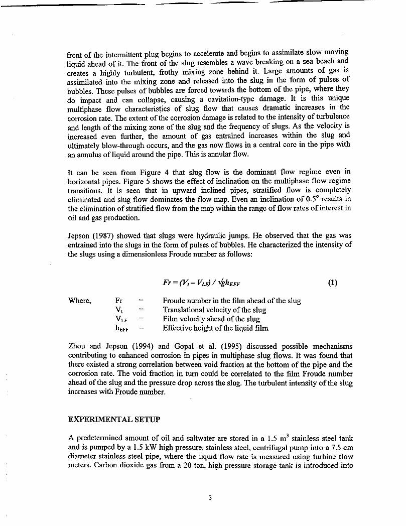
Jepson (1987) showed that slugs were hydraulic jumps. He observed that the gas wasentrained into the slugs in the form of pulses of bubbles. He characterized the intensity ofthe slugs using a dimensionless Froude number as follows:
Where, Froude number in the film ahead of the slugTranslational velocity of the slugFilm velocity ahead of the slugEffective height of the liquid film
(1)
Zhou and Jepson (1994) and Gopal et al. (1995) discussed possible mechanismscontributing to enhanced corrosion in pipes in multiphase slug flows. It was found thatthere existed a strong correlation between void fraction at the bottom of the pipe and thecorrosion rate. The void fraction in turn could be correlated to the film Froude numberahead of the slug and the pressure drop across the slug. The turbulent intensity of the slugincreases with Froude number.
EXPE~NTALSETUPA predetermined amount of oil and saltwater are stored in a 1.5 m3 stainless steel tankand is pumped by a 1.5 kW high pressure, stainless steel, centrifugal pump into a 7.5 cmdiameter stainless steel pipe, where the liquid flow rate is measured using turbine flowmeters. Carbon dioxide gas from a 20-ton, high pressure storage tank is introduced into
3
the system and its flow rate is measured using inline, magnetic flow meters. Thegas/oil/water mixture then flows through a 10-cm diameter, 40-m long, high pressure,high temperature, fully inclinable, stainless steel pipe, where all the multiphase flow andcorrosion measurements are made. The multiphase mixture then flows through a 10-cmdiameter pipe and is recycled into the system by a unique, Moyno, triphaze pump that canhandle up to 99% gas. The 40-m length is divided into two 20-m sections with an inlineseparator. Both upward and downward flows can be studied simultaneously using thissystem. The system can be operated up to 150 bars and a temperature of 150 C. Aschematic of the system is shown in Figure 6.
TEST SECTION
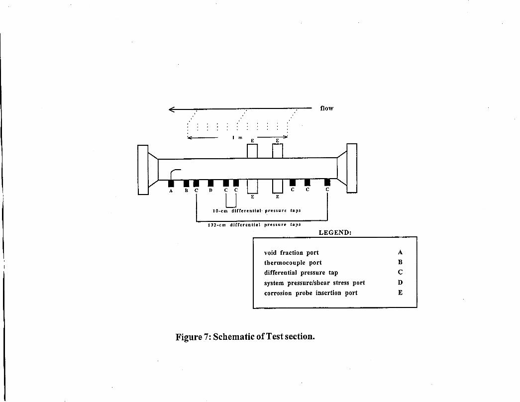
Figure 7 shows a schematic of the test section. The test section consists of a 10-cmdiameter, 2-m long, stainless steel pipe with ports for inserting corrosion probes and formeasurement of multiphase flow characteristics including, phase and velocity profilesacross the vertical diameter and pressure drop due to the flow.
There are two ports each (E) at the top and bottom of the pipe for inserting electricalresistance (ER) probes for corrosion measurement. The probes are mounted flush withthe inside pipe wall to allow determination of corrosion rate at the six and twelve o-clockpositions. Electrochemical probes such as electrochemical impedance spectroscopy (EIS),electrochemical noise (ECN), and DC polarization can also be used. Limiting currentdensity values (LCD) from DC polarization experiments can be used to determine a masstransfer coefficient that can be correlated to pressure drop and shear stress.
The test section has several pressure taps (C) to measure the instantaneous pressuregradient at different distances in the flow. A patented non-visual technique to determinemultiphase flow regimes based on pressure drop and velocity measurements has beendeveloped at the Center using these ports. D is a pressure port that can also be used toinsert a flush-mounted, hot film probe to determine instantaneous wall shear stress. Thiscan then be correlated to the pressure drop. A sampling port (A) is used to insert a pitottube into the test section and determine instantaneous velocity profiles in the multiphaseflow. The tube can also be used to withdi:aw isokinetic samples of the flowing mixture todetermine flow characteristics such as oil/water fractions, holdup of liquid and gas, andheight of the liquid film in stratified flow. The iron and oxygen contents of the solutioncan also be monitored using this port. Details of the multiphase flow systems and theexperiments carried out have presented in several previous papers (e.g., Sun and Jepson,1992, Jepson et aI., 1996, Maley, 1997a).
Also, a patented, noninvasive, ultrasonic multiphase flow and corrosion measurementsystem is currently under development at the Center to determine flow characteristicssuch as film height distribution, holdup variation, and average phase velocities and metalthickness loss down to 10 microns. The current state-of-the-art is 25 microns using theField Signal Method (FSM). The ultrasonic corrosion measurement system is also beingdesigned to determine corrosion mechanisms using special mathematical analysis of thereceived signals.
4
TEST MATRIX
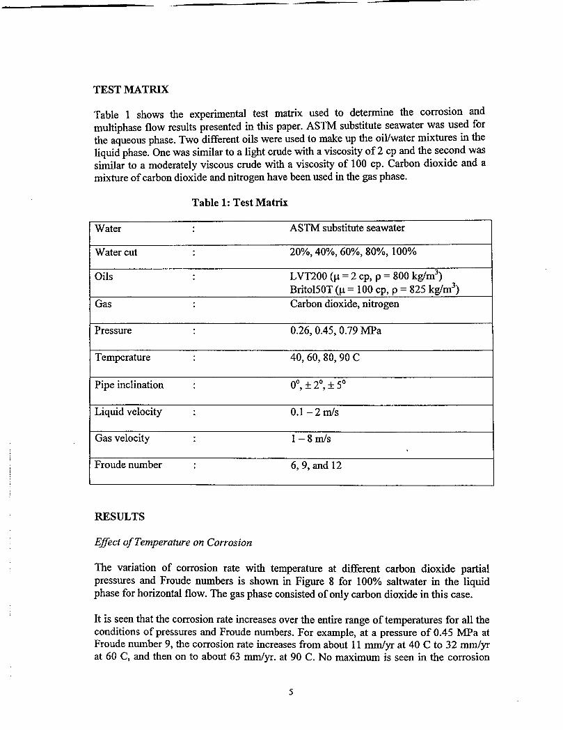
Table I shows the experimental test matrix used to determine the corrosion andmultiphase flow results presented in this paper. ASTM substitute seawater was used forthe aqueous phase. Two different oils were used to make up the oil/water mixtures in theliquid phase. One was similar to a light crude with a viscosity of 2 cp and the second wassimilar to a moderately viscous crude with a viscosity of 100 cpo Carbon dioxide and amixture of carbon dioxide and nitrogen have been used in the gas phase.
Table 1: Test Matrix
Water . ASTM substitute seawater.Water cut . 20~,40~,60~,80~, 100~
Oils LVT100 (Jl = 2 cp, P = 800 kglm3)Britol50T (Jl = 100 cp, P = 825 kglm3)
Gas Carbon dioxide, nitrogen
Pressure 0.26,0.45,0.79 MPa
Temperature 40, 60, 80, 90 C
Pipe inclination 0°, :f: 2°, :f: 5°
Liquid velocity . 0.1-2 mls
Gas velocity . 1- 8 mls .Froude number 6,9, and 12
RESULTS
Effect of Temperature on Corrosion
The variation of corrosion rate with temperature at different carbon dioxide partialpressures and Froude numbers is shown in Figure 8 for IOO~ saltwater in the liquidphase for horizontal flow. The gas phase consisted of only carbon dioxide in this case.
It is seen that the corrosion rate increases over the entire range of temperatures for all theconditions of pressures and Froude numbers. For example, at a pressure of 0.45 MPa atFroude number 9, the corrosion rate increases from about 11 mm/yr at 40 C to 32 mm/yrat 60 C, and then on to about 63 mm/yr. at 90 C. No maximum is seen in the corrosion
5
rates over the entire range of temperature studied. This is contrary to the prediction by deWaard and Milliams (1975). This is true for all multiphase flow-enhanced sweetcorrosion of carbon steel. Figure 9 shows the variation of corrosion rate with temperaturefor 80% water cut and the results are similar to those of Figure 8. No maximum incorrosion is observed, and the corrosion rate increases with temperature at all carbondioxide partial pressures and for all Froude numbers. For example, at a carbon dioxidepartial pressure of 0.27 MPa at Froude number 12, the corrosion rate increases fromabout 8.2 mm/yr. at 40 C to about 12.5 nun/yr. at 60 C, and then on to 19.5 mm/yr. at 80C. Detailed description of these results are given in Bhongale (1996).
Slug Flow Characteristics
Slug flow involves unique multiphase characteristics not seen in other flow regimes, asdescribed earlier. The turbulent mixing zone involves entrainment of large amounts ofgas, which is released into the slug in the form of pulses of bubbles that are forcedtowards the bottom of the pipe. The frequency and turbulent intensity of the pulses ofbubbles increases with Froude number and these mechanisms have been described inearlier papers (Gopal et aI., 1995). The gas bubbles do impact and can collapse on thepipe wall, causing the corrosion product to be removed from surface and enhancinglocalized corrosion.
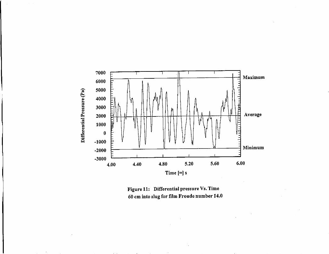
The effect of the turbulence of these pulses of bubbles on wall shear stress, pressure drop,and mass transfer is shown in Figures 10, 11, and 12.
Figure 10 shows the variation of instantaneous wall shear stress within the mixing zone.of the slug at a Froude number of 14 for 100% water cut. Details of the measurementsand the discussion of the results can be found in Maley (1997b). It is seen thatfluctuations of about 40 Pa around an average shear stress value of 120 Pa are seen atregular frequencies. The intensities and frequency of these fluctuations have been shownto increase with Froude number (Maley, 1997b). Fourier analysis shows the frequenciesto correspond with those of the pulses of bubbles in the mixing zone observed visually.
Figure 11 presents the results of the instantaneous pressure fluctuations within the mixingzone of the slug at the same conditions as Figure 10. It can been seen that fluctuationssimilar to those seen in the wall shear stress occur here as well. Pressure fluctuations ofabout 4000 Pa are seen at regular intervals about a mean value of 2000 Pa. The frequencyof the fluctuations is similar to those seen in Figure 10.
The pressure and shear stress results can be correlated for slug flow. It has beensuggested by Efird (1993) that the effect of flow on corrosion can be quantified using thewall shear stress. Since the shear stress is both difficult to measure and calculate for slugflow, the correlation between wall shear and pressure drop has allowed the use ofpressure gradient as a function of Froude number in a predictive corrosion modeldeveloped at the Center. The pressure drop then indicates the level of gas entrainmentwithin the mixing zone and the consequent turbulent intensity associated with it.
6
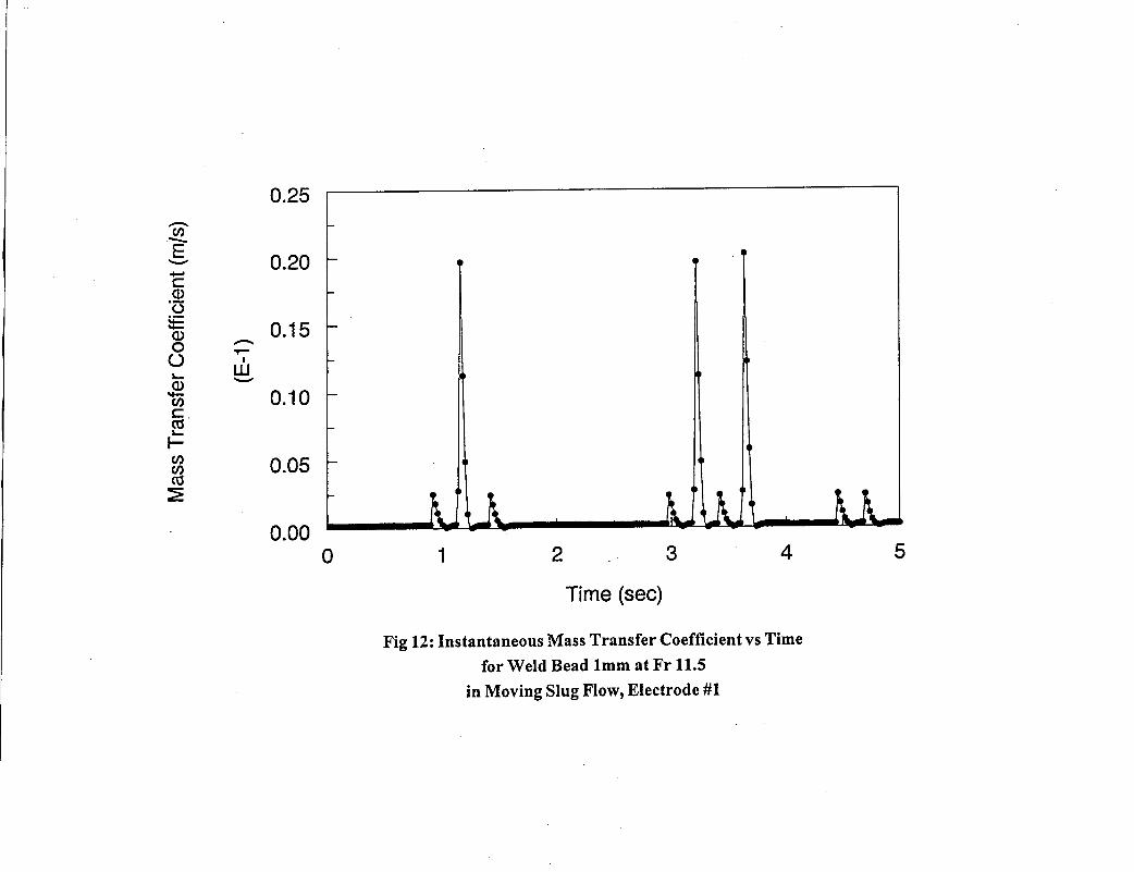
The results from mass transfer measurements using limiting current densitymeasurements in slug flow at a Froude number of about 12 are shown in Figure 12.Details of these results have been presented elsewhere (Jiang and Gopal, 1998a and b).Peaks at regular intervals are observed. For example, at times of 1, 1.5,3 and 3.5 s, peaksten times the average value are seen. At time instants of 1.25,3.25 and 3.75 s, peaks 100times the average value, are observed. Again, the large amplitude fluctuations around amean value are indicative of the impact of gas bubbles on the electrode surface within themixing zone of the slug. Work is currently going on at the Center to correlate masstransfer with Froude number and slug frequency to predict the effect of multiphase slugflow on the transport of corrosive species to the pipe wall and consequently its effect oncorrosion rate.
A three-dimensional video image of the mixing zone of the slug is captured in Figure 13.The large amount of gas entrained within the slug is clearly understood from this image.It is also easily seen that the entrained gas is forced towards the bottom of the pipe as thefront of the slug rolls over and assimilates slow moving liquid and gas ahead of it. Theresults from Figures 10, 11, and 12 can be explained as above in the light of this image.
Effect of Liquid Viscosity
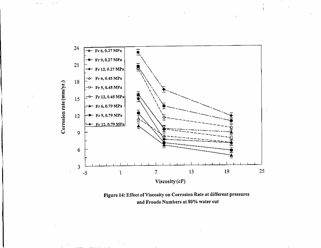
The effect of liquid viscosity on the sweet corrosion rate in multiphase flows is describedin Figure 14. It is seen that the corrosion decreases significantly as the viscosity increasesfrom 2 to 8 cp and then slowly as the viscosity increases further to about 20 cpo Forexample, at 0.79 MPa at Froude number 12, the corrosion rate decreases from 23.5rnm/yr. to 17 rnm/yr. as the viscosity increases from 2 to 8 cp and then to 12 rnm/yr. witha decrease in viscosity to 20 cpo
As the liquid phase viscosity increases, the level of turbulence within the mixing zonedecreases. This is shown by the reduction of pressure drop across the slug. This results inless entrainment of gas and less shear at the wall of the pipe. This results in less erosionof the corrosion product layer and less corrosion.
Effect of Gas Density
The effect of multiphase slug flow on corrosion can also be described using gas densityas a variable. As the carbon dioxide partial pressure increases, the corrosion rateincreases due to a pH effect, which is well known. However, with increase in systempressure, there is an increase in gas density, which increases the turbulence and wallshear stress associated with the pulses of bubbles.
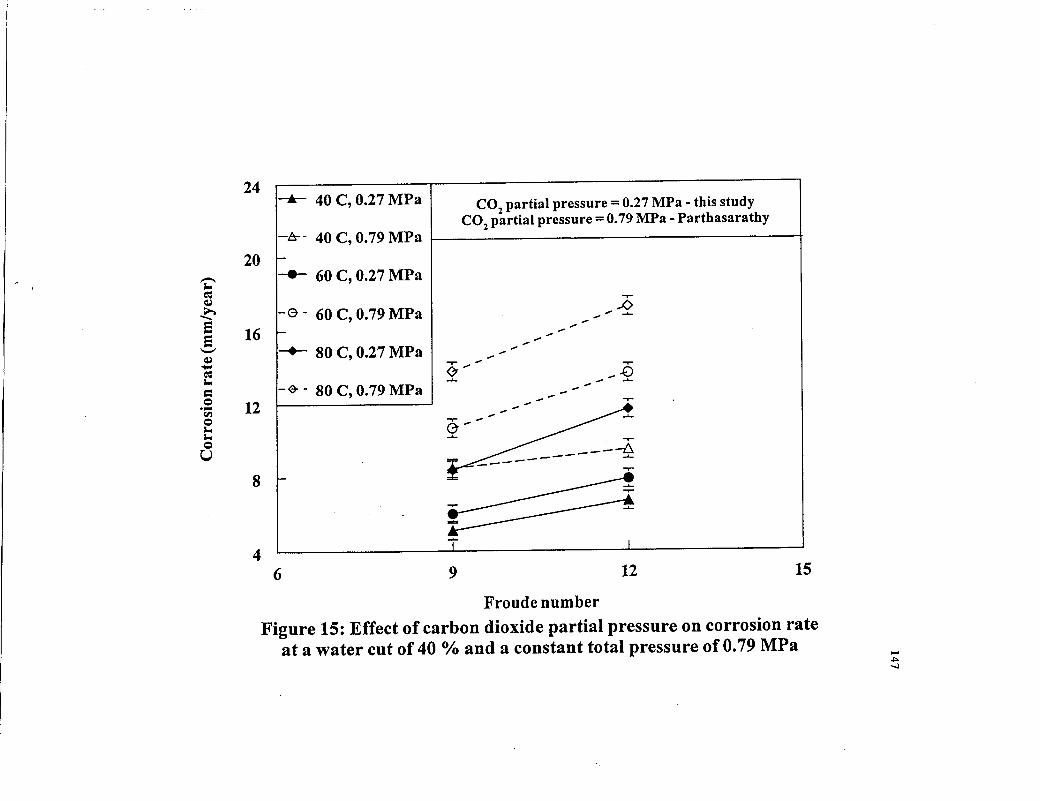
Figure 15 shows the effect of gas density on the corrosion rate in slug flow. The figurecompares corrosion rate at a total system pressure of 0.79 MPa. In one case, the gas phaseconsists solely of carbon dioxide and in the second case, a mixture of carbon dioxide andnitrogen is used. The partial pressure of carbon dioxide in the second case is 0.27 MPa. Itis seen that corrosion rate increases because of gas density at the same pH. For example,the corrosion rate at 0.27 MPa partial pressure of pure carbon dioxide at a Froude numberof 9 at 80 C is 5.8 rnm/yr. With the carbon dioxide partial pressure kept constant (i.e.
7

same pH), when the total pressure is increased to 0.79 MPa, the corrosion rate increasesto 8.1 mm/yr. This is lower than the value of 14.2 mm/yr obtained with 0.79 MFa purecarbon dioxide pressure, but still shows a significant increase over the baseline corrosionrate. Similar results are seen at Froude number 12.
Froude Number Effects
Figure 15 also shows the effect of increasing Froude number on corrosion rate. At 60 Cwith a carbon dioxide partial pressure of 0.79 MFa, the corrosion rate increases from 10.1mm/yr to 13.2 mm/yr. as the Froude number is increased from 9 to 12. Increasing theFroude number results in increased turbulence and gas entrainment within the mixingzone of the slug. This results in higher wall shear stress and pressure drop across the slugwith associated increases in the corrosion rate.
Effect of Inclination
As mentioned earlier, inclining a pipe by even half a degree can cause the elimination ofstratified flow in upward multiphase flow and a dominant slug flow regime can occur.Also, owing to gravity effects, the height of the liquid film increases, resulting in anincrease in the slug frequency. Further, rollback of liquid down the pipe, can result in anincrease in the Froude number. Both effects contribute to increase the corrosion rates inupward inclined pipes. In downward flow, the dominant flow regime is stratified.
The variation of Froude number with superficial gas velocity for various superficialliquid velocities is shown in Figure 16. It is seen that the Froude number increaseslinearly with gas velocity. This is expected since, at higher gas velocities, the in situ gasvelocity controls the slug translational velocity, and the liquid velocity is not muchdifferent. It should be noted from Figure 16 that slug flow with Froude numbers close to5 can be observed even at liquid velocities as low as 0.1 m/s and gas velocities less than 2m/s in upward inclined pipes.
Jepson and Taylor (1988) proposed a correlation for slug frequency in horizontal flow.Figure 17 compares the observed average slug frequency in 2° and 5° upward flows withtheir correlation as a function of the mixture velocity. It can be seen that upwardinclination results in significant increases in slug frequency. A generalized correlation forslug frequency as a function of inclination has been developed at the Center.
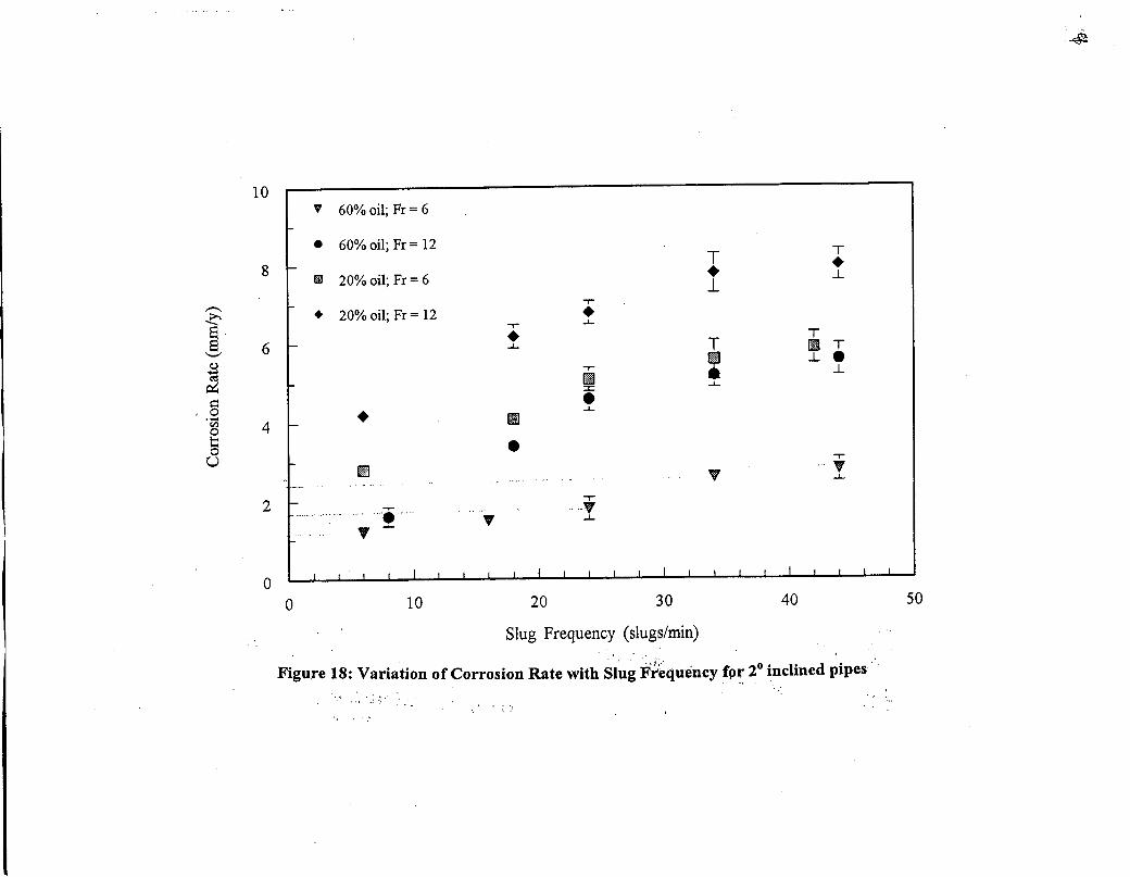
The effect of slug frequency on corrosion rates at two different Froude numbers is shownin Figure 18 for 2° upward flows at a carbon dioxide partial pressure of 0.27 MFa. It canbe seen the corrosion rate increases approximately linearly with slug frequency up toabout 35 slugs/min. It then tends to remain constant with increasing slug frequency. Forexample, with 20% oil at Froude number 12, the corrosion rate increases linearly fromabout 4.1 mm/yr. to 7.5 mm/yr. with increase in slug frequency from 6 slugs/min to 34slugs/min and remains at approximately the same value at a higher frequency of 44slugs/min. Similar results are seen at other Froude numbers, water cuts, pressures andtemperatures.
8

With increasing slug frequency, the effect of the turbulence of the mixing zone .on thecorroding surface increases. At lower slug frequencies, the product film along Wl~ anyinhibitor may have a chance to repair itself before encountering a second slug. At higherslug frequencies, this repair process is hindered and at a critical frequency of about 35slugs/min, the effect of the turbulence of the mixing zone becomes permanent and furtherincreases in slug frequency h~ve little effect.
Corrosion Rate Model
Based on the extensive database of corrosion and multiphase slug flow characteristicsgenerated at the Center, a predictive model for sweet corrosion of carbon steel in slugflow has been developed. The model includes separate terms for carbon dioxide partialpressure, temperature (these determine the pH of the system), water cut, pressure dropacross the slug (which is a direct function of Froude number), gas density, liquidviscosity, and slug frequency. Based on the results of Efird (1989), the model alsoincludes the effect of crude oil based on the acid number and percent nitrogen of the .crude. The model is available to member companies.
Electrochemical Methods
The corrosion mechanisms in multiphase flows and the effect of the flow on inhibitorperformance can be determined using different electrochemical techniques. These arebeing developed at the Center and the details are given elsewhere (Chen, 1998 a,b).
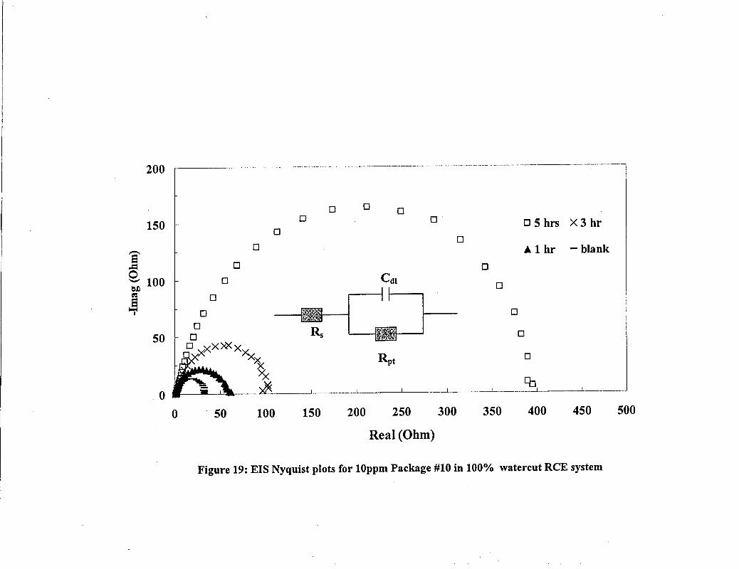
Figure 19 depicts the electrochemical impedance spectroscopy (EIS) Nyquist plot for aninhibitor used in 100% salt water. The equivalent circuit used to fit the experimental datato a model is also shown. It is seen that a uniform film of inhibitor exists on the corrosionsurface and the resulting circuit can be described with one surface resistance with onetime constant. The increasing diameter of the semi-circle shows higher resistance tocorrosion which is indicative of a protective film. This can then be compared to thespectra seen in Figure 20, which shows the result for an inhibited surface exposed to slugflow at Froude number 9. Here, a combination of a one time-constant resistance with aWarburg diffusion element in the electrical circuit is needed to describe the surfacebehavior. The reason is the disruption of the uniformity of the film due to slug flow. Thepulses of gas bubbles described earlier, upon impact and possible collapse on the surface,possess enough energy to rupture binding of the inhibitor/corrosion product layer with themetal surface. This can result in "holes" or impact craters on the layers which can allowdiffusion of the corrosive species to the metal surface resulting in degradation of theinhibitor.
Effect of Iron
It has been suggested, following de Waard and Milliams, that under certain conditions,the iron carbonate corrosion product layer, may become protective and prevent furthercorrosion. These conditions have been termed "scaling conditions".
9

Figure 21 shows a comparison of corrosion rates in slug flow under conditions ofnegligible iron in the solution with dissolved iron increased to the limit of negligiblecorrosion under oil/water full pipe flow conditions. It can be seen that increasing the ironconcentration in the solution has resulted in a decrease in corrosion but it is not negligibleunder slug flow. For example, at a carbon dioxide partial pressure of 0.79 MPa, thecorrosion rate for Froude number 6 with no iron is 28 mm/yr. and increases to 33 mm/yr.at Froude number 12. The corresponding rates are 13.5 mm/yr. and 16 mm/yr. with 95ppm dissolved iron.
Surface Analysis
The reason for the continued corrosion of carbon steel in slug flow, even under "scalingconditions" can be seen from Figures 22 and 23. Figure 22 shows the corrosion surfaceunder full pipe oil/water flow conditions. It is seen that the surface is covered with auniform film of corrosion product. It is densely packed and consequently fully protective.When this surface is compared with the one shown in Figure 23, which shows thecorrosion layer exposed to slug flow, it is seen that parts of the layer have been removedrevealing "holes" with the underlying metal surface being exposed. This is typical of thedamage caused by slug flow due to the impact and possible collapse of the gas bubbles inthe mixing zone. In some cases, the corrosion product layer is removed completely fromthe surface. Details of this study will be presented elsewhere (Gopal and Rajappa, 1999).
Conclusions
A detailed study on the effect of multiphase flows on sweet corrosion of carbon steelpipes has been carried out at pressures up to 0.79 MPa and temperature up to 90 C.Multiphase flow has been shown to have a dramatic effect on corrosion rates of carbonsteel.
Slug flow is the dominant flow regime in multiphase pipelines. Stratified flow iseliminated even at inclinations of 0.5°. This results in dramatic increases in corrosionrates.
Slug flow involves unique mechanisms with large amounts of gas entrainment within theliquid slug. The gas is released within a turbulent mixing zone in the form of pulses ofbubbles that are forced towards the bottom of the pipe. The bubbles do impact andpossibly collapse on the pipe surface causing a cavitation-type effect, which results insignificant localized corrosion. The turbulence and frequency of these pulses of bubblesis a strong function of the Froude number in the film ahead of the slug.
Froude number and slug frequency increase due to gravity effects in upward inclinedflows, thereby increasing corrosion.
The corrosion increases linearly with slug frequency until about 35 slugs/min and thenremains constant.
10

No maximum is seen in corrosion rates with increasing temperature over the rangestudied. Corrosion also increases with carbon dioxide partial pressure and Froudenumber.
The corrosion rate decreases with increasing viscosity due to a reduction in turbulence.
Gas density does have a separate mechanical effect on the corrosion rate in slug flow dueto the pulses of bubbles in the mixing zone.
Shear stress, turbulent intensity, pressure drop, and mass transfer measurements all showsimilar fluctuations at regular time intervals within the mixing zone of the slug. Thissupports the visual observations about the pulses of bubbles within the mixing zone.
EIS technique is able to detect corrosion mechanisms and equivalent circuit modelspredict the existence of a uniform or damaged film on the corroding surface.
A predictive model for corrosion of carbon steel in slug flow has been developed. Themodel includes the effect of carbon dioxide partial pressure, temperature, pressure dropacross the slug, water cut, gas density, oil viscosity, slug frequency, and crude oil type.
Increasing the iron content beyond saturation limits to reach scaling conditions does notprotect the pipe from further corrosion in slug flow. SEM micrographs show impactcraters consistent with bubble impact that cause severe damage to the corrosion productlayer, resulting in continued localized corrosion.
References
1. Bhongale, S., "Effect of Pressure, Temperature, and Froude Number on Corrosionunder Horizontal Multiphase Flow", M.S. Thesis, Ohio University, 1996.
2. Chen, Y., and Gopal, M., "Electrochemical Methods for Determining CorroionInhibition Mechanisms in Multphase Flows, " Corrosion/99, paper no. 509, (Houston,TX: NACE futernational, 1999).
3. Chen, Y. Chen, H., and Jepson, W. P., "Effect of Multiphase Flow on CorrosionInhibition", Corrosion/99, paper no. 12, (Houston, TX: NACE futernational, 1999).
4. De Waard C., and Milliams, D. E., "Carbonic Acid Corrosion of Steel", Corrosion,31,5 (1975): p. 177.
5. De Waard, C., Lotz, U., and Milliams, D. E., "Predictive Model for CO2 CorrosionEngineering in Wet Natural Gas Pipelines", Corrosion, 47, 12 (1991): p. 76.
6. De Waard, C., Lotz, U., and Dugstad, D., "fufluence of Liquid Flow Velocity on CO2Corrosion: A Semi-Empirical Model," Corrosion/95, paper no. 128, (Houston, TX:NACE International, 1995).
7. Efird, D. E., "Effect of the Crude Oil on the Corrosion of Steel in Crude oil/BrineProduction", Corrosion, 45, 2, Feb. 1989.
8. Efird, K. D., Wright, E. J., Boros, J. A., and Hailey, T. G., "Wall Shear Stress andFlow Accelerated Corrosion of Carbon Steel in Sweet Production", 12th International
11
Corrosion Congress, Technical paper TS 14 194, (Houston, TX: NACE International,1993).
9. Gopal, M., Kaul, A., and Jepson, W. P., "Mechanisms Contributing To EnhancedCorrosion in Three Phase Slug Flow in Horizontal Pipes", Corrosion/95, paper no.105, (Houston, TX: NACE International, 1995).
10. Gopal, M., and Rajappa, S., "Effect of Multiphase Slug Flow on the Stability ofCorrosion Product Layers," Corrosion/99, paper no. 46, (Houston, TX: NACEInternational, 1999).
11. Jepson, W. P., "The Flow Characteristics in Horizontal Slug Flow", 3ed Int. Conf. OnMultiphase Flow", Paper F2, 187 (1987).
12. Jepson, W. P., and Taylor, R. E., "Slug Flow and its Transitions in Large DiameterHorizontal Pipes", AERE-RI2992, Harwell Laboratories, U.K., 1988.
13. Jepson, W. P., Bhongale, S., and Gopal, M., "Predictive Model for Sweet Corrosionin Horizontal Multiphase Slug Flow", Corrosion/96, paper no. 19, (Houston, TX:NACE International, 1996).
14. Jepson, W. P., Stitzel, S., Kang, C., and Gopal, M., "Model for Sweet Corrosion inHorizontal Multiphase Slug Flow", Corrosion/97, paper no. 602, (Houston, TX:NACE International, 1997).
15. Jiang, L., and Gopal, M., "Calculation of Mass Transfer in Multiphase Flow",Corrosion/98, paper no. 50, (Houston, TX: NACE International, 1998).
16. Maley, J., "Slug Flow Characteristics and Corrosion Rates in Inclined, High Pressure,Multiphase Flow Pipes", M.S. Thesis, Ohio University, 1997.
17. Maley, L., "A Study of Slug Flow Characteristics in Large Diameter, HorizontalMultiphase Pipelines", M.S. Thesis, Ohio University, 1997.
18. Nesic, S., Postlethwaithe, J., and Olsen, S., (1995), "An electrochemical model forprediction of CO2 Corrosion", Corrosion/95, paper no. 131, (Houston, TX: NACEInternational, 1995
19. Sun, J-Y, and Jepson, W. P., "Slug Flow Characteristics and their Effect on CorrosionRates in Horizontal Oil and Gas Pipelines", SPE 1992, paper no. 24787, (Houston,TX: SPE, 1992).
20. Zhou, X., and Jepson, W. P., "Corrosion in Three-Phase OillWater/Gas Slug Flow inHorizontal Pipes", Corrosion/94, paper no. 26, (Houston, TX: NACE International,1994).
12
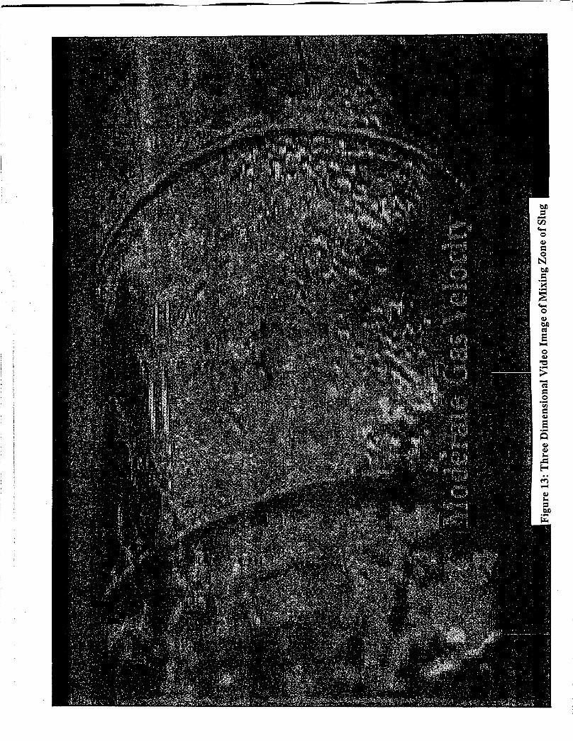
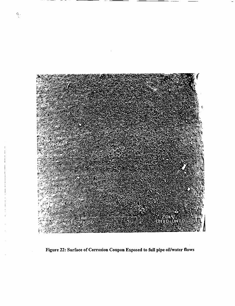
Figure 22: Surface of Corrosion Coupon Exposed to full pipe oiVwater flows

2
1 rSlug Flow
I \ AnnularSlug
II-.rn-a--.eo~
Rolling...•
~
u0
Wave~>rn~C-' I
SmoothStratified
0.1
0.050.5 1 10 20
Liquid Velocity (m/s)
Figure 4: Flow regime map for multiphase horizontal flow


2I
-/ t::. t::.t::.••••
1 l- ./ t::. t::. t::. ••plug flow •• I••
I ••slug flow ••
f- I••'-t:::. t::. t::.t::. • ••CI:l
~
I ••E •• I,........, ••.!!... I ••••- ICI:l ••> ••
I •••••• pseudo slug I••I •••••• •!0.1 I- •• t::. t::. t::./ ••
•• I••
0.05 I I ! ! l, I
0.5 1 10 20
Vsg [=] mls
Figure 5: Flow regime map for 40% ASTM seawater, 20 inclination, 0.27 MPa

centrifugal pump
separator
plate
test section
eparator
LEGEND;
pressure gauge (!)temperature gauge 0flow gauge (1)check valve KJ I mixing tankgate valve t><Jball valve ~
rupture disk 8compression flange DXIl
Figure 6: High-pressure, inclinable flow system process flowsheet.
~
I m
E E
"",'
flow
IO-em differential, pressure taps
132-em differential pressure taps
LEGEND:
void fraction portthermocouple portdifferential pressure tapsystem pressure/shear stress portcorrosion probe insertion port
Figure 7: Schematic of Test section.
AB
CDE
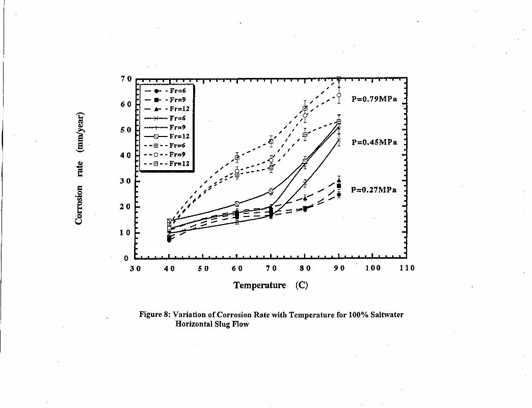
Figure 8: Variation of Corrosion Rate with Temperature for 100% SaltwaterHorizontal Slug Flow

10090
P=0.79MPa
P=0.27MPa
80706050
~~~ ~,~ ~' ~~ ,
~" ,, , ,, ~ ,", , ,, , "P~ ~,'
~ ,,,r ,"~ ~ ~, ¥ ', ~, ,, ,", ~ ~, ~", ,~, ,
~ ~ ~,~,,"•...
40
• Fr=6_Fr=12
- -83 _. Fr=6- -6 _. Fr=9- -51_. Fr=U
o30
20
30
10
50
40
~e
iQ,l
i:!
~.-~
8
Temperature (C)
Figure 9: Variation of Corrosion Rate with Temperature for 80% Saltwater,Horizontal Slug Flow

Minimum Shear
Average Shear
Maximum Shear
175
150-~~ 125rIlrIl~"'" 100-rJ.l
"'"~~ 75.c::rJ.l--~ 50~
25
00.00 0.20 0.40 0.60 0.80 1.00
Time (=) s
Figure 10: Wall Shear Stress Vs. Time for 60 eminto the slug and a film Froude number 14.0
Minimum
Average
Maximum
6.005.605.20
Time [=) s
7000
6000- 5000~e;,4000~~=Vol 3000Vol~~
~ 2000-~.•...•.• 1000Cl~~0~
""".•..~ -1000
-2000
-30004.00 4.40 4.80
Figure 11: Differential pressure Vs. Time60 em into slug for film Froude number 14.0
0.25-en-E 0.20.•....•..+-'cQ)'0:e 0.15Q) -0 ,...() I
W'"- .•....•..Q)
0.10-enc.m'"-f-en 0.05~:2:
0.00a 1 2
Time (sec)
3 4 5
Fig 12: Instantaneous Mass Transfer Coefficient vs Timefor Weld Bead Imm at Fr 11.5
in Moving Slug Flow, Electrode #1
24I ---.Iir- Fr 6, 0.27 MPa
-e- Fr 9, 0.27 MPa21
-+- Fr 12, 0.27 MPa
-. 18 •-lr Fr 6, 0.45 MPaa.:<-==== 15 ~ Fr 12, 0.45 MPa.......,~.•..~""= r+- Fr 9, 0.79 MPa0 12...•In0
"" r-+- Fr 12. 0.79 MPa""0U 9
6
•~\i '\.\ ''\ \,,\ '
'\'\ ~---....-, --.... ----' ' ...•.•.. ---....\"--- ------..' -'- ----------- =' ---.!--------------~
----------- -+-----------------..•.._--------------'-
3-5 1 7
Viscosity (cP)
13 19 25
Figure 14: Effect of Viscosity on Corrosion Rate at different pressuresand Froude Numbers at 80% water cut
24.....- 40 C, 0.27 MPa
-A- - 40 C, 0.79 MPa
CO2partial pressure = 0.27MPa - this study
CO2partial pressure = 0.79MPa - Parthasarathy
1512
......0...•.•
..0.............•..
_----....:.-----.:E....•..
9
0--...•.•
~~~...•.•
-+- 80 C, 0.27 MPa
-6 - 60 C, 0.79 MPa
-~ - 80 C, 0.79 MPa
- 60 C, 0.27 MPa
6
8
4
12
16
20'i:'1:1:~~ee--~••••E=o...•v.le~oU
Froude numberFigure 15: Effect of carbon dioxide partial pressure on corrosion rateat a water cut of 40 % and a constant total pressure of 0.79 MPa -,j>.-..l

30Vsl ••••
• 0.1 m/s • 0.5 m/s y 1.0 m/s II 1.5 m/s
25 L
•.11,-:.-1l •.1i
• y V•• III...,.• ft..yB' • ••.- ...~.
:,,~ •• 4&'11.""•.....,'" ..,... .I I I •
••• y ••
.y y.
••y.• •
~20 I-
1Z 15.g
I-
=0~
10 I-
5 I-
oo 2 4 6
•
•
.1
8
•
10
Superficial Gas Velocity (mls)
Figure 16: Fronde number results @ 5° for all pressure and compositions

1
.-CIl:>-S- 0.1*'+-<'-"
Jepsonffaylor ---
--
2° correlation - 5° correlation
+--
+
0.01o 2 4 6 8 10 12
Mixture Velocity - Vm (m/s)
Figure 17: Jepson/Taylor (1989) results compared with the correlations developed in this study
10v 60% oil; Fr = 6
• 60% oil; Fr = 12
8 ~ I!l.l 20% oil; Fr = 6
,.-.. [-r
>. • 20% oil; Fr = 12 •] -r .J...
6 •.J...'-"Cl) -r~ ~~ :z::~ •0 • .J.......• ~<Il 40b •0u 1m
2 t- -r~ ....•.. .. :v! .. ••• .J...
"
T•1.
T:.J...
v
T•.LT~ T..L •
.L
-rV.J...
.. ",
.~
oo 10 20 30 40 50
Slug Frequency (slugs/min)
Figure 18: Variation of Corrosion Rate with Slug F~~quency f9~ 2° ~nclinedpipes'.. . ... ,.
. ....
200
450 500
- blank
400
Al hr
o
05 hrs X 3 hr
o
o
o
350
o
o
300
oo
250
Cd1
o
200
o
150
oo
100
oo
o
50
oooo ~ R
pto XX~XXx Cb ,~X "k _~. ~'X, _L.. _'x I __
___•.•. ~_. 1- .. _._. __..••..•..•...1...
50
oo
150
a-=Q, 100bJ)a~
Real (Ohm)
Figure 19: EIS Nyquist plots for 10ppm Package #10 in 100% watercut RCE system

200 ,--- - -------.----.--.-- ...
03.5 hrs
X2.5 hrs.•.1.5 hrs
- 0.5 hrs
..L-. __--l __ ~__ _L._ _._ ~•...... 1.__. I .J f __ .l __-L , __L _
o 0 0 0 0 0
Sl: ~xx XXXXDDD. >tJlb9<9:... .•..•. .•. .•..•. X X 0 0 ~Xo
IX... .•. .•. .•. X 0 0M'" _---- .•. Xx EDI:A_-- --_ .•..•. x~x~~
~~ -... - &~£-. ---- .•..•..LeA .•..•..•.----...-,.--
, !o
150
S..=i 100 I~
50
o 100 200 300 400 500 600 700Real (Ohm)
Figure 20: EIS Nyquist plots for 100ppm Package #18 in 100% watercut under Froude 9 slug flow

1412108
T,,"'iJ
"..... ..L••...••...
T T .'1-_---------'9" .......L ..L
6
T95 ppm dis~olved iron T
k_---------k----------...L ..L ..L
T T~------ _--BT T +fr A -8-'- 110ppm dfsso1ved iron-'-
42
0.79 MPa, this study
0.79 MPa, Bhongale(1995)
:--e- 0.27 MPa, Bhongale(1995)
o
35
5
29
23
17
11
'l:'~~.cee--~.•..~'"'=o.-v.lo'"''"'o
U
Froude number
Figure 21: Comparison of corrosion rates at different pressuresand Froude numbers at 40% water cut and 80 C