modelling oedometer tests on biocemented soils …
TRANSCRIPT
Congresso de Métodos Numéricos em Engenharia
1-3 julho 2019, Guimarães, Portugal
Universidade do Minho
MODELLING OEDOMETER TESTS ON BIOCEMENTED SOILS
CONSIDERING BONDS PRESENCE
R. Cardoso1, I. Borges
2 e I. Pires
3
1: IST/CERIS, University of Lisbon, Portugal
e-mail: [email protected]
2: IST, University of Lisbon, Portugal
e-mail: [email protected]
3: former IST, University of Lisbon, Portugal
e-mail: [email protected]
Key-words: Biocementation, bonds, constitutive modelling, structured material,
elastoplasticity, damage
Abstract Biocementation is being used mainly to improve the mechanical and hydraulic
properties of soils. This technique consists in adding bacteria and feeding solution to soils
to produce calcium carbonate (biocement). When produced in enough quantity, calcium
carbonate formed around bacteria present in the soil pores create bonds connecting the
particles. The treated material is therefore a bonded material, also considered to be an
artificially structured material. In this paper oedometer tests performed on saturated
samples of a sandy soil treated with bacteria were simulated using an elastoplastic
constitutive model for bonded materials. The model is defined based on Cam Clay Model
considering the destructured state as reference case, and a bonding parameter which
increases the size of the yielding surface. This parameter is reduced during loading due to
bonds' progressive failure, simulating damage. In this study the results of similar tests
performed on identical samples not submitted to treatment were used as reference case.
Two different definitions of the bonding parameter were adopted: (i) the definition used
for soft rocks, in which bonding is defined mathematically; (ii) bonding is defined
considering explicitly the presence and number of connections. Model calibration is
discussed for the two definitions, being more simple for case (i). Nevertheless, case (ii) is
based on physical properties and is more realistic than case (i). Both cases are consistent
and the model is able to reproduce the behaviour of the biocemented material.
1. INTRODUCTION
Biocementation is being used mainly to improve the mechanical and hydraulic properties of
soils. It is a green technique with huge potential in geotechnical applications [1]. This
technique consists in adding bacteria and feeding solution to soils to produce calcium
carbonate, the biocement, which clogs the soil pores and bonds the grains, changing the
hydro-mechanical (HM) properties of the soil [2]. Several are the applications predicted for
this treatment, such as: prevention of internal erosion [3,4] and liquefaction [5,6], soil
strengthening for foundations, excavation or drilling [7], etc. Only few large scale tests were
R. Cardoso, I. Borges e I. Pires
performed in treated sands [8,9].
Calcium carbonate CaCO3 is precipitated after the hydrolysis of urea made by the
microorganisms, resulting in ammonium (NH4+) and carbonate ions (CO3
2-):
CO(NH2)2 + 2H2O 2NH4+ + CO3
2- (1)
Calcium carbonate results from the reaction between the carbonate ions and calcium ions
supplied in the feeding solution:
Ca2+
+ CO32-
CaCO3 (2)
When produced in enough quantity, calcium carbonate formed around bacteria present in
the soil pores create bonds connecting the particles. The treated material is therefore a
bonded material, also considered to be an artificially structured material.
Oedometer tests performed on saturated samples of a sandy soil treated with bacteria were
simulated using an elastoplastic constitutive model for bonded materials. The model used,
presented by Gens & Nova [10] is defined based on Cam Clay Model considering the
destructured state as reference case, and a bonding parameter which increases the size of
the yielding surface. This parameter is reduced during loading due to bonds' progressive
failure, simulating damage. This parameter is reduced during loading due to bonds'
progressive failure, simulating damage. The results of similar tests performed on identical
samples not submitted to treatment were used as reference case. Two different definitions
of the bonding parameter were adopted. The first considered the definition for soft rocks
proposed by Gens and Nova [10], in which bonding is defined mathematically. The
second follows the definition proposed by Gajo and co-authors [11], in which bonding is
defined considering explicitly the presence and number of connections.
2. NUMERICAL MODEL
2.1. General definition
In artificially cemented materials stiffness and strength depend on bonds presence, and it is
natural to assume that these mechanical properties will reduce as bonds break during loading.
In this case, the amount of active bonds (bonds contributing to stiffness and strength)
decrease. The limit case is when there are no active bonds, which is the fully destructured
case, or the reference case. In this paper two different definitions of the bonds are adopted, the
first following the definition proposed by Gens and Nova [10], and the second by Gajo et al.
[11]. They are described as follows.
2.2. Bonding parameter defined numerically
Gens and Nova [10] defined a model for soft rocks based on modified Cam Clay Model, in
which bonding is quantified by bonding parameter b. The values of b are limited by b=b0 (the
bonds are intact) and b=0 (fully debonded case). At a fully debonded case volume changes are
free to occur and stiffness for stress changes reaches the minimum value. By adopting
intermediate values of b it is possible to simulate progressive loss of structure, or debonding.
The definition of this parameter is
R. Cardoso, I. Borges e I. Pires
(3)
with
(4)
where b0, h0, h1 and h2 are constants, and d pand e
are total and volumetric plastic
deformations, respectively.
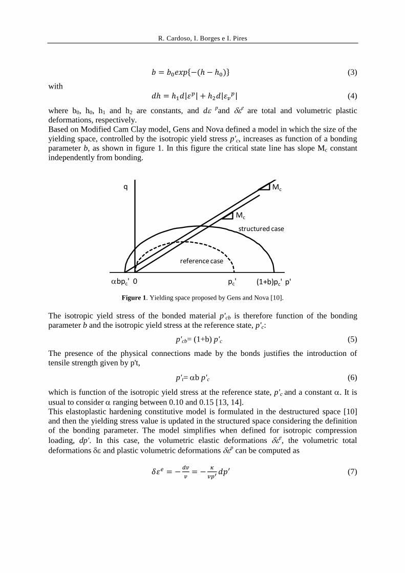
Based on Modified Cam Clay model, Gens and Nova defined a model in which the size of the
yielding space, controlled by the isotropic yield stress p'c, increases as function of a bonding
parameter b, as shown in figure 1. In this figure the critical state line has slope Mc constant
independently from bonding.
Figure 1. Yielding space proposed by Gens and Nova [10].
The isotropic yield stress of the bonded material p'cb is therefore function of the bonding
parameter b and the isotropic yield stress at the reference state, p'c:
p'cb= (1+b) p'c (5)
The presence of the physical connections made by the bonds justifies the introduction of
tensile strength given by p't,
p't= b p'c (6)
which is function of the isotropic yield stress at the reference state, p'c and a constant . It is
usual to consider ranging between 0.10 and 0.15 [13, 14].
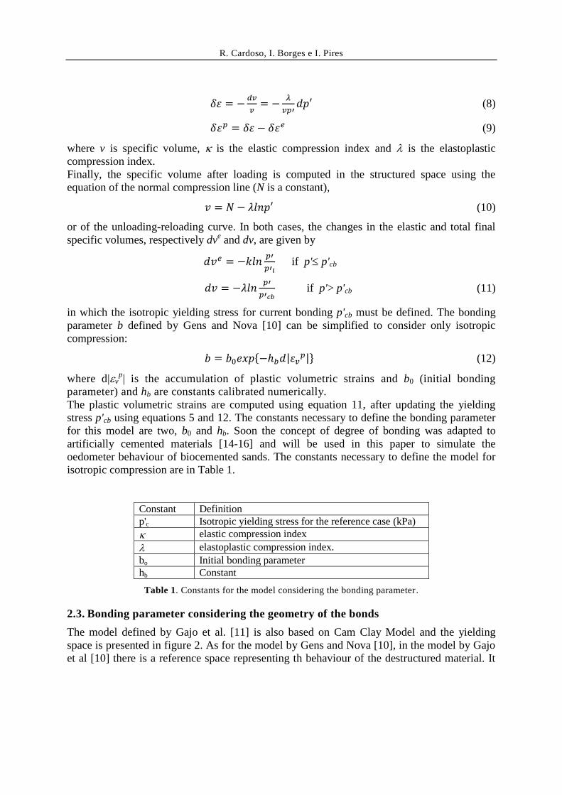
This elastoplastic hardening constitutive model is formulated in the destructured space [10]
and then the yielding stress value is updated in the structured space considering the definition
of the bonding parameter. The model simplifies when defined for isotropic compression
loading, dp'. In this case, the volumetric elastic deformations e, the volumetric total
deformations and plastic volumetric deformations p can be computed as
(7)
q
p'pc' (1+b)pc'bpc' 0
Mc
Mc
reference case
structured case
R. Cardoso, I. Borges e I. Pires
(8)
(9)
where v is specific volume, is the elastic compression index and is the elastoplastic
compression index.
Finally, the specific volume after loading is computed in the structured space using the
equation of the normal compression line (N is a constant),
(10)
or of the unloading-reloading curve. In both cases, the changes in the elastic and total final
specific volumes, respectively dve and dv, are given by
if p' p'cb
if p'> p'cb (11)
in which the isotropic yielding stress for current bonding p'cb must be defined. The bonding
parameter b defined by Gens and Nova [10] can be simplified to consider only isotropic
compression:
(12)
where d|vp| is the accumulation of plastic volumetric strains and b0 (initial bonding
parameter) and hb are constants calibrated numerically.
The plastic volumetric strains are computed using equation 11, after updating the yielding
stress p'cb using equations 5 and 12. The constants necessary to define the bonding parameter
for this model are two, b0 and hb. Soon the concept of degree of bonding was adapted to
artificially cemented materials [14-16] and will be used in this paper to simulate the
oedometer behaviour of biocemented sands. The constants necessary to define the model for
isotropic compression are in Table 1.
Constant Definition p'c Isotropic yielding stress for the reference case (kPa)
elastic compression index
elastoplastic compression index.
bo Initial bonding parameter hb Constant
Table 1. Constants for the model considering the bonding parameter.
2.3. Bonding parameter considering the geometry of the bonds
The model defined by Gajo et al. [11] is also based on Cam Clay Model and the yielding
space is presented in figure 2. As for the model by Gens and Nova [10], in the model by Gajo
et al [10] there is a reference space representing th behaviour of the destructured material. It
R. Cardoso, I. Borges e I. Pires
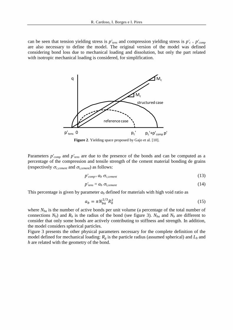
can be seen that tension yielding stress is p'tens and compression yielding stress is p'c + p'comp
are also necessary to define the model. The original version of the model was defined
considering bond loss due to mechanical loading and dissolution, but only the part related
with isotropic mechanical loading is considered, for simplification.
Figure 2. Yielding space proposed by Gajo et al. [10].
Parameters p'comp and p'tens are due to the presence of the bonds and can be computed as a
percentage of the compression and tensile strength of the cement material bonding de grains
(respectively c,cement and t,cement) as follows:
p'comp= ab c,cement (13)
p'tens = ab t,cement (14)
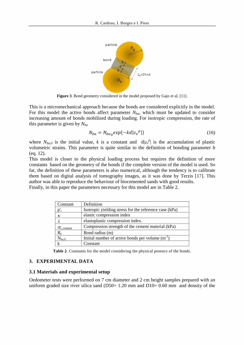
This percentage is given by parameter ab defined for materials with high void ratio as
(15)
where Nba is the number of active bonds per unit volume (a percentage of the total number of
connections Nb) and Rb is the radius of the bond (see figure 3). Nba and Nb are different to
consider that only some bonds are actively contributing to stiffness and strength. In addition,
the model considers spherical particles.
Figure 3 presents the other physical parameters necessary for the complete definition of the
model defined for mechanical loading: Rg is the particle radius (assumed spherical) and Lb and
h are related with the geometry of the bond.
q
p'pc' pc'+p'compp'tens 0
Mc
Mc
reference case
structured case
R. Cardoso, I. Borges e I. Pires
Figure 3. Bond geometry considered in the model proposed by Gajo et al. [11].
This is a micromechanical approach because the bonds are considered explicitly in the model.
For this model the active bonds affect parameter Nba, which must be updated to consider
increasing amount of bonds mobilized during loading. For isotropic compression, the rate of
this parameter is given by Nba
(16)
where Nba,0 is the initial value, k is a constant and d|vp| is the accumulation of plastic
volumetric strains. This parameter is quite similar to the definition of bonding parameter b
(eq. 12).
This model is closer to the physical loading process but requires the definition of more
constants based on the geometry of the bonds if the complete version of the model is used. So
far, the definition of these parameters is also numerical, although the tendency is to calibrate
them based on digital analysis of tomography images, as it was done by Terzis [17]. This
author was able to reproduce the behaviour of biocemented sands with good results.
Finally, in this paper the parameters necessary for this model are in Table 2.
Constant Definition p'c Isotropic yielding stress for the reference case (kPa)
elastic compression index
elastoplastic compression index.
c,cement Compression strength of the cement material (kPa)
Rb Bond radius (m) Nba,0 Initial number of active bonds per volume (m
-3)
k Constant
Table 2. Constants for the model considering the physical pesence of the bonds.
3. EXPERIMENTAL DATA
3.1 Materials and experimental setup
Oedometer tests were performed on 7 cm diameter and 2 cm height samples prepared with an
uniform graded size river silica sand (D50= 1.20 mm and D10= 0.60 mm and density of the
R. Cardoso, I. Borges e I. Pires
solid particles Gs= 2.65). Two different kind of samples were prepared: (i) with water and
without treatment, to provide data on the destructured material, and (ii) with bacteria, to
which feeding solution was added to promote the precipitation of biocement. Both kind had
the same void ratio of 0.9 at preparation. The volume of bacteria solution used in sample
preparation is the volume of voids computed with this void ratio, assuming that the material
would be saturated in the oedometer ring.
The bacterial species used is Sporoscarcina Pasteurii, which is non-pathogenic and can be
found in soils. It was supplied by American Type Culture Collection (strain #11859).
Optimum conditions for growing are pH between 8 and 9 and temperature closer to 36ºC. S.
Pasteurii was cultured in a liquid medium composed by 20 g/l yeast extract, 10 g/l of
ammonium sulphate and 0.13 M Tris buffer pH 9.0, at 37°C under aerobic condition, up to a
cell density of 108 cells/mL (optical density at 600nm of 1). The feeding solution was
prepared with 1:10 diluted culture medium supplement (20 g/l yeast extract, 10 g/l of
ammonium sulphate and 0.13 M Tris buffer pH 9.0) with 0.5 M of urea and 0.5 M of calcium
chloride (calcium source).
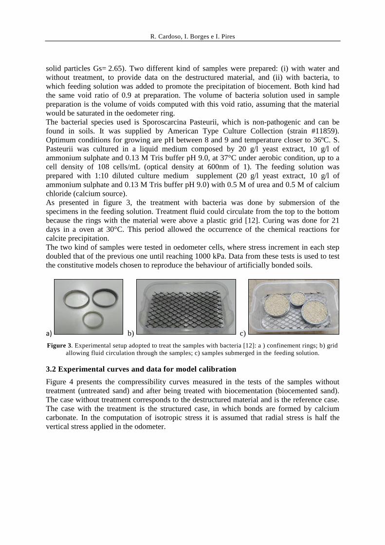
As presented in figure 3, the treatment with bacteria was done by submersion of the
specimens in the feeding solution. Treatment fluid could circulate from the top to the bottom
because the rings with the material were above a plastic grid [12]. Curing was done for 21
days in a oven at 30°C. This period allowed the occurrence of the chemical reactions for
calcite precipitation.
The two kind of samples were tested in oedometer cells, where stress increment in each step
doubled that of the previous one until reaching 1000 kPa. Data from these tests is used to test
the constitutive models chosen to reproduce the behaviour of artificially bonded soils.
a) b) c)
Figure 3. Experimental setup adopted to treat the samples with bacteria [12]: a ) confinement rings; b) grid
allowing fluid circulation through the samples; c) samples submerged in the feeding solution.
3.2 Experimental curves and data for model calibration
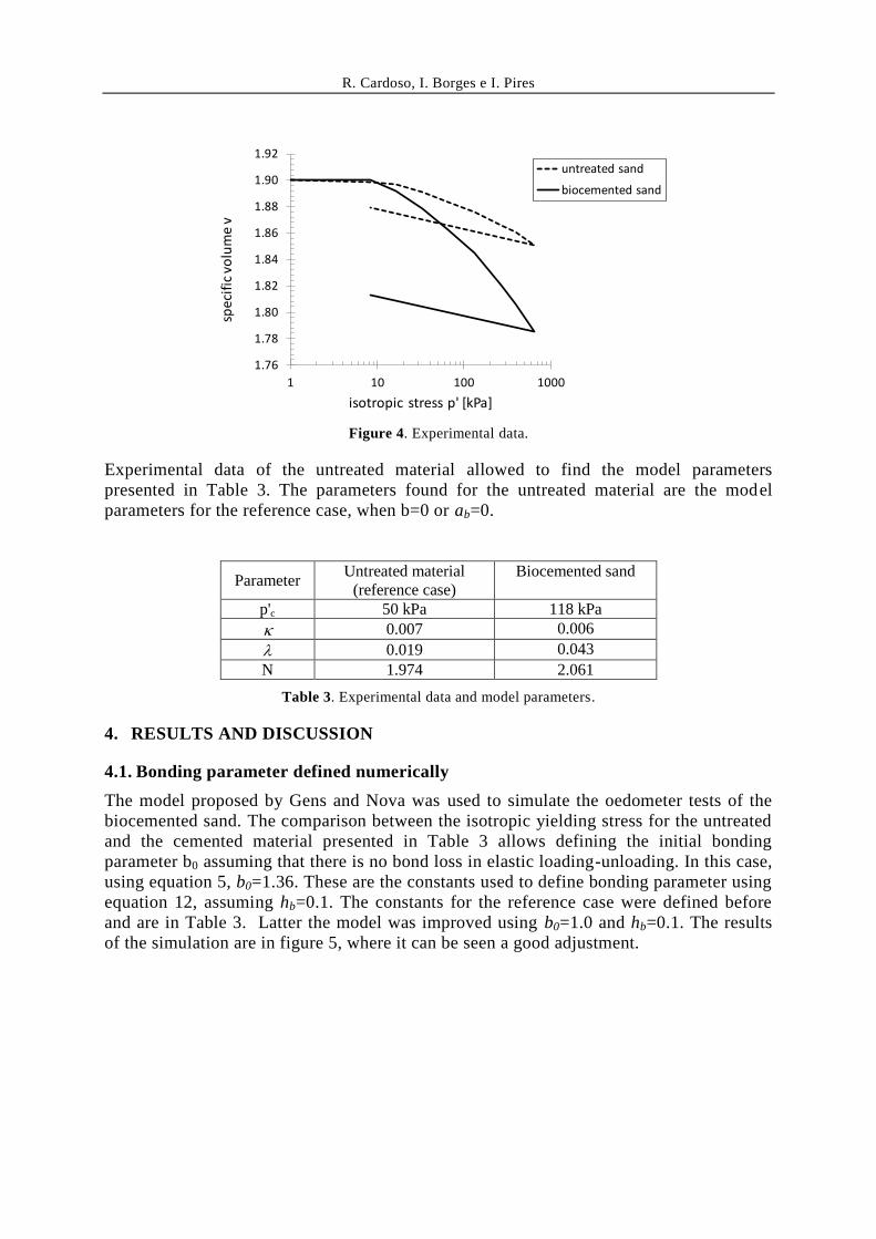
Figure 4 presents the compressibility curves measured in the tests of the samples without
treatment (untreated sand) and after being treated with biocementation (biocemented sand).
The case without treatment corresponds to the destructured material and is the reference case.
The case with the treatment is the structured case, in which bonds are formed by calcium
carbonate. In the computation of isotropic stress it is assumed that radial stress is half the
vertical stress applied in the odometer.
R. Cardoso, I. Borges e I. Pires
Figure 4. Experimental data.
Experimental data of the untreated material allowed to find the model parameters
presented in Table 3. The parameters found for the untreated material are the model
parameters for the reference case, when b=0 or ab=0.
Parameter Untreated material
(reference case) Biocemented sand
p'c 50 kPa 118 kPa
0.007 0.006
0.019 0.043
N 1.974 2.061
Table 3. Experimental data and model parameters.
4. RESULTS AND DISCUSSION
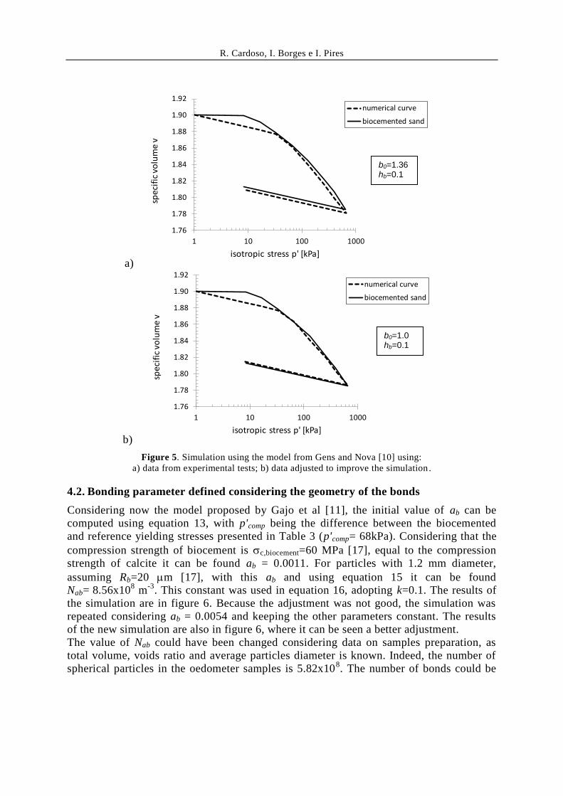
4.1. Bonding parameter defined numerically
The model proposed by Gens and Nova was used to simulate the oedometer tests of the
biocemented sand. The comparison between the isotropic yielding stress for the untreated
and the cemented material presented in Table 3 allows defining the initial bonding
parameter b0 assuming that there is no bond loss in elastic loading-unloading. In this case,
using equation 5, b0=1.36. These are the constants used to define bonding parameter using
equation 12, assuming hb=0.1. The constants for the reference case were defined before
and are in Table 3. Latter the model was improved using b0=1.0 and hb=0.1. The results
of the simulation are in figure 5, where it can be seen a good adjustment.
1.76
1.78
1.80
1.82
1.84
1.86
1.88
1.90
1.92
1 10 100 1000
spec
ific
vo
lum
e v
isotropic stress p' [kPa]
untreated sand
biocemented sand
R. Cardoso, I. Borges e I. Pires
a)
b)
Figure 5. Simulation using the model from Gens and Nova [10] using:
a) data from experimental tests; b) data adjusted to improve the simulation .
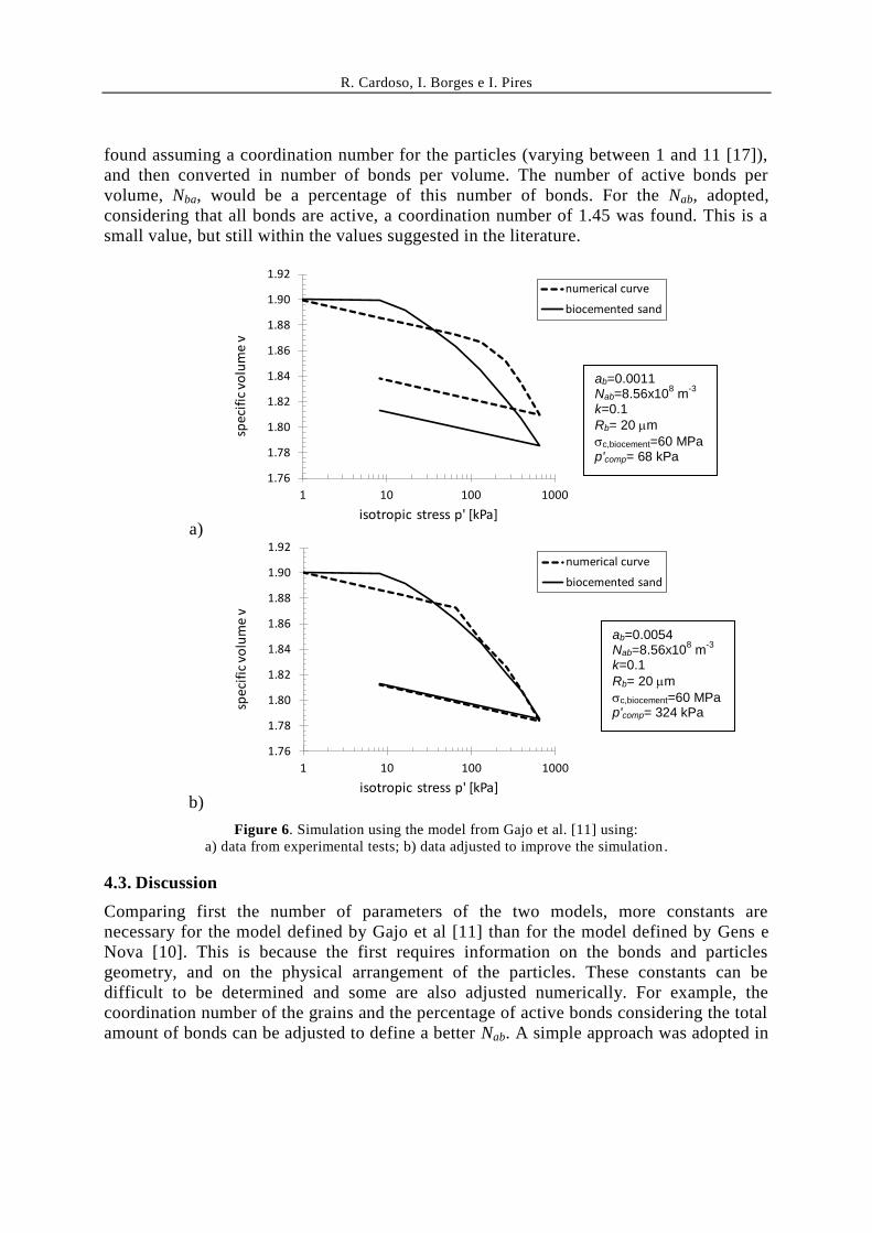
4.2. Bonding parameter defined considering the geometry of the bonds
Considering now the model proposed by Gajo et al [11], the initial value of ab can be
computed using equation 13, with p'comp being the difference between the biocemented
and reference yielding stresses presented in Table 3 (p'comp= 68kPa). Considering that the
compression strength of biocement is c,biocement=60 MPa [17], equal to the compression
strength of calcite it can be found ab = 0.0011. For particles with 1.2 mm diameter,
assuming Rb=20 m [17], with this ab and using equation 15 it can be found
Nab= 8.56x10⁸ m
-3. This constant was used in equation 16, adopting k=0.1. The results of
the simulation are in figure 6. Because the adjustment was not good, the simulation was
repeated considering ab = 0.0054 and keeping the other parameters constant. The results
of the new simulation are also in figure 6, where it can be seen a better adjustment.
The value of Nab could have been changed considering data on samples preparation, as
total volume, voids ratio and average particles diameter is known. Indeed, the number of
spherical particles in the oedometer samples is 5.82x10⁸. The number of bonds could be
1.76
1.78
1.80
1.82
1.84
1.86
1.88
1.90
1.92
1 10 100 1000
spec
ific
vo
lum
e v
isotropic stress p' [kPa]
numerical curve
biocemented sand
1.76
1.78
1.80
1.82
1.84
1.86
1.88
1.90
1.92
1 10 100 1000
spec
ific
vo
lum
e v
isotropic stress p' [kPa]
numerical curve
biocemented sand
b0=1.36 hb=0.1
b0=1.0 hb=0.1
R. Cardoso, I. Borges e I. Pires
found assuming a coordination number for the particles (varying between 1 and 11 [17]),
and then converted in number of bonds per volume. The number of active bonds per
volume, Nba, would be a percentage of this number of bonds. For the Nab, adopted,
considering that all bonds are active, a coordination number of 1.45 was found. This is a
small value, but still within the values suggested in the literature.
a)
b)
Figure 6. Simulation using the model from Gajo et al. [11] using:
a) data from experimental tests; b) data adjusted to improve the simulation .
4.3. Discussion
Comparing first the number of parameters of the two models, more constants are
necessary for the model defined by Gajo et al [11] than for the model defined by Gens e
Nova [10]. This is because the first requires information on the bonds and particles
geometry, and on the physical arrangement of the particles. These constants can be
difficult to be determined and some are also adjusted numerically. For example, the
coordination number of the grains and the percentage of active bonds considering the total
amount of bonds can be adjusted to define a better Nab. A simple approach was adopted in
1.76
1.78
1.80
1.82
1.84
1.86
1.88
1.90
1.92
1 10 100 1000
spec
ific
vo
lum
e v
isotropic stress p' [kPa]
numerical curve
biocemented sand
1.76
1.78
1.80
1.82
1.84
1.86
1.88
1.90
1.92
1 10 100 1000
spec
ific
vo
lum
e v
isotropic stress p' [kPa]
numerical curve
biocemented sand
ab=0.0011 Nab=8.56x10
8 m
-3
k=0.1
Rb= 20 m
c,biocement=60 MPa p'comp= 68 kPa
ab=0.0054 Nab=8.56x10
8 m
-3
k=0.1
Rb= 20 m
c,biocement=60 MPa p'comp= 324 kPa
R. Cardoso, I. Borges e I. Pires
this paper using available experimental data.
The comparison of the two models (Figs.5b) and 6b)) allows concluding that both are able
to reproduce the behaviour of the biocemented material. However the model from Gens e
Nova [10] appears to be better than the one of Gajo et al [11] in adjusting the transition
between the elastic and elastoplastic behavior. This may be because a simplified version
of the model from Gajo et al [11] was adopted, valid only for materials with high voids
ratio.
6. CONCLUSIONS
The models from Gens and Nova [10] and Gajo et al [11] were adopted to simulate the
mechanical behaviour of biocemented sand under oedometric compression. The first
model only requires the definition of the bonding parameter and destructuring law and is
calibrated numerically. The second model adopts a micromechanical approach and
therefore requires the definition of more constants related with the geometry of the bonds.
The difficulty on calibration will certainly be solved in the future by using optimization
techniques, for example using genetic algorithms. In addition, recent visualization
techniques such as tomography can be used to define intervals for the calibration
parameters. Some contribution can also came from simulations of identical materials
using discrete elements models in which bonds are incorporated.
The two models appear to adjust well the experimental curves, although a simplified
version of the model from Gajo et al [11] was adopted. This confirms that the mechanical
behaviour of biocemented materials can be adjusted using models for artificially
structured materials, where bonds presence and their progressive loss during mechanical
loading are taken into consideration.
ACKNOWLEDGEMENTS
The authors acknowledge Professor Gabriel Monteiro from IBB for helping in bacteria
preparation, and funding from FCT project BIOSOIL, ref. PTDC/ECI-EGC/32590/2017.
REFERENCES
[1] DeJong, JT, Soga, K., Kavazanjian, E., Burns, S., Van Paassen, L. A. , Al Qabany,
A., Aydilek, A., Bang, S. S., Burbank, M., Caslake, L. F.. Chen, C. Y., Cheng, X.,
Chu, J., Ciurli, S., Esnault-Filet, A., Fauriel, S., Hamdan, N., Hata, T., Inagaki, Y.,
Jefferis, S., Kuo, M., Laloui, L., Larrahondo, J., Manning, D.A.C., Martinez, B.,
Montoya, B.M., Nelson, D.C., Palomino, A., Renforth, P., Santamarina, J.C.,
Seagren, E.A., Tanyu, B., Tsesarsky, M. and Weaver, T. (2013). Biogeochemical
processes and geotechnical applications: progress, opportunities and challenges.
Geotechnique, 63: 287–301.
[2] Terzis, D., Bernier-Latmani, R. and Laloui, L (2016). Fabric characteristics and
mechanical response of bio-improved sand to various treatment conditions.
Geotechnique letters, 6(1)
[3] Chu, J., Ivanov, V., Stabnikov, V (2013). Microbial method for construction of
aquaculture pond in sand. Géotechnique, 63: 871–875.
R. Cardoso, I. Borges e I. Pires
[4] Salifu, E., MacLachlan, E., Iyer, K.R., Knapp, C.W. and Tarantino, A. (2016).
Application of microbially induced calcite precipitation in erosion mitigat ion and
stabilisation of sandy soil foreshore slopes: A preliminary investigation.
Engineering Geology, 201: 96–105
[5] DeJong, J.T., Fritzges, M.B, Nusslein, K. (2006). Microbially induced cementation
to control sand response to undrained shear. J. Geotechnical and Geoenvironmental
Engineering,132: 1381-1392.
[6] Montoya, B. M., DeJong, J., Boulanger, R. (2013). Dynamic response of
liquefiable sand improved by microbial-induced calcite precipitation,
Geotechnique, 63 (4): 302–312.
[7] Latil, M.-N., Van der Zon, W., Lehnen, C., Ineke, E., Marcelis, F., Van Eijden, J.,
Baaijens, T., Baaijens, T. Bol, G. (2008). Environmental friendly technology for
biological sand-consolidation of oil and gas wellbore, Proc. 1st Bio-Geo Engng
Conf., Deltares:. 82–89.
[8] Van Paassen, L., Ghose, R., van der Linden, T., van der Star, W. & Van
Loosdrecht, M. (2010). Quantifying Biomediated Ground Improvement by
Ureolysis: Large-scale Biogrout Experiment. J. Geotechnical and
Geoenvironmental Engineering, 136: 1721-1728.
[9] Gomez, M., Martinez, M., DeJong, J.T., Hunt, C. de Vlaming, L. Major, D.
Dworatzek, S. (2015). Field-scale bio-cementation tests to improve sands. Ground
Improvement, Proceedings of the Institution of Civil Engineers, ICE , 168 (3): 206-
216.
[10] Gens A. and Nova R. (1993). Conceptual bases for a constitutive model for bonded
soils e weak rocks. Geotechnical Engineering of Hard Soils – Soft Rocks, Balkema,
Rotterdam, pp. 485-494.
[11] Gajo, A., Cecinato, F. and Hueckel, T. (2015). A micro-scale inspired chemo-
mechanical model of bonded geomaterials. International Journal of Rock
Mechanics e Mining Sciences, 80, pp. 425-438.
[12] Pires, I. (2016). Effect on soil biocementation of the presence of fines. MSc Thesis.
Instituto Superior Técnico, Universidade de Lisboa, Portugal (in Portuguese)
[13] Consoli, N., Cruz, R., Floss, M. e Festugato, L. (2010). Parameters controlling
tensile e compressive strength of artificially cemented sand. Journal of
Geotechnical e Geoenvironmental Engineering, v. 136, pp. 759-763
[14] Cardoso, R., Ribeiro, D e Néri, R. (2017). Bonding effect on compressive e tensile
strength of sand-cement mixtures. Soils e Foundations, 57, pp. 655–668.
[15] Rios, S., Ciantia, M., Gonzalez, N., Arroyo, M, e Viana da Fonseca, A. (2016).
Simplifying calibration of bonded elasto-plastic models. Computers e Geotechnics,
73, pp. 100-108.
[16] Ribeiro, D. (2017). Prediction of the hydro-mechanical behaviour of jet grouting
columns. PhD Thesis. Instituto Superior Técnico, Universidade de Lisboa,
Portugal.
[17] Terzis, D (2017). Kinetics, Mechanics e Microstructure of Bio-cemented soils. PhD
Thesis, Ecóle Polytechnique Federale de Lausanne, Suiça.