modelling of vibratory pile driving in sand
TRANSCRIPT

INTERNATIONAL JOURNAL FOR NUMERICAL AND ANALYTICAL METHODS IN GEOMECHANICS, VOL. 16, 189-210 (1992)
MODELLING OF VIBRATORY PILE DRIVING IN SAND
DANIEL WONG *
McBride Ratcliff Associates, Houston, TX 77040, U.S.A.
MICHAEL W. ONEILL' AND C . VIPULANANDANg
Department of Civil and Environmental Engineering, University of Houston, Houston, TX 77204-4791, U.S.A.
SUMMARY
A model for vibro-driving of rigid piles in sand is proposed incorporating the interaction of the vibrator-pile-soil system. The vibro-driver force and the non-linear soil resistance (dynamicf-w and q-w relationships) have been quantified in terms of in situ stress, relative density and particle size. The influence of relative density (0.65 and 0.90), particle size (effective grain size of 0.2 mm and 1.2 mm) and in situ stress (up to 20 psi) on the vibro-driving of a closed-ended pipe pile was investigated experimentally using a large-scale laboratory testing system. The vibro-driving model predicted the observed driving history reasonably well. A computer program (UHVIBRO) has been developed to analyse vibratory pile driving using the dynamic soil resistance relationships developed along with correlation factors from the systematic laboratory study.
INTRODUCTION
Pile installation by vibro-driving is a relatively recent foundation practice that is gaining in popularity. Most vibro-drivers in the field are vibrated at frequencies ranging from 5 to 40 Hz and are classified as low-frequency drivers. Vibro-driving of piles results in faster rates of penetration and less noise and damage to the pile compared to impact driving under favourable soil conditions. Vibrating the pile during driving serves to reduce the soil resistance and thus permit faster penetration. Static surcharge (bias mass) is usually placed on the vibrator to assist the vertical forcing function for driving the piles. A spring system is used to separate the bias mass and to prevent it from vibrating with the driver. The vibrator is attached to the pile with either a chuck-type or pin-type connection.
A limited number of laboratory model studies and full-scale studies have been conducted on the influence of vibro-driver parameters on the behaviour of vibro-driven piles'-4 but the mechanism of vibrator-pileesoil interaction has not been modelled in a fundamental way. Furthermore, little has been done to investigate the influence of soil parameters (particle size, volume change characteristics, density) and in situ stress conditions on pile driveability. This shortcoming has hindered the application of the vibro-driving technique.
The major objective of this paper is to propose a model for vibro-driving of piles and to verify it with large-scale laboratory tests. The success of the proposed model relies on the proper quantification of the interaction between the vibro-driver and pile, and soil and pile during
* Staff Engineer ' Professor and Chairman Associate Professor
O363-9O61/92/O3O189-22$11.00 19 1992 by John Wiley & Sons, Ltd.
Received 26 October 1989 Revised 22 July 1991
190 D. WONG. M. W. ONEILL AND C. VIPULANANDAN
driving. Hence, the proposed vibro-driving model incorporates the vibro-driving force, the dynamic soil behaviour and radiation damping through the surrounding soil. A computer program (UHVIBRO) was developed based on the proposed model. It employs correlated parameters obtained from the results of large-scale laboratory tests.
BACKGROUND
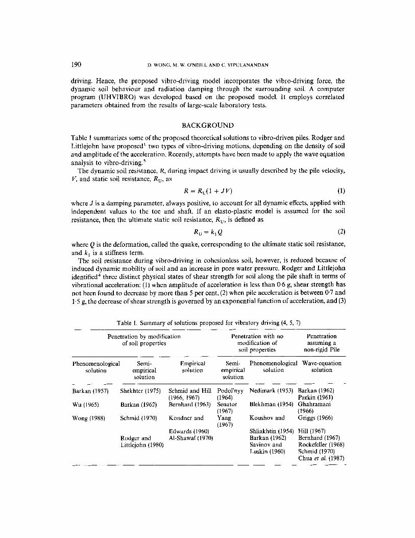
Table 1 summarizes some of the proposed theoretical solutions to vibro-driven piles. Rodger and Littlejohn have proposed' two types of vibro-driving motions, depending on the density of soil and amplitude of the acceleration. Recently, attempts have been made to apply the wave equation analysis to vibro-dri~ing.~
The dynamic soil resistance, R, during impact driving is usually described by the pile velocity, V, and static soil resistance, R,, as
R = RU(1 + J V ) (1) where J is a damping parameter, always positive, to account for all dynamic effects, applied with independent values to the toe and shaft. If an elasto-plastic model is assumed for the soil resistance, then the ultimate static soil resistance, R,, is defined as
where Q is the deformation, called the quake, corresponding to the ultimate static soil resistance, and k , is a stiffness term.
The soil resistance during vibro-driving in cohesionless soil, however, is reduced because of induced dynamic mobility of soil and an increase in pore water pressure. Rodger and Littlejohn identified4 three distinct physical states of shear strength for soil along the pile shaft in terms of vibrational acceleration: (1) when amplitude of acceleration is less than 0 6 g, shear strength has not been found to decrease by more than 5 per cent, (2) when pile acceleration is between 0 7 and 1.5 g, the decrease of shear strength is governed by an exponential function of acceleration, and (3)
Table I. Summary of solutions proposed for vibratory driving (4, 5, 7)
Penetration by modification of soil properties
Penetration with no Penetration modification of assuming a soil properties non-rigid Pile
Phenomenological Semi- Empirical solution empirical solution
solution
Barkan (1957) Shekhter (1975) Schmid and Hill
Wu (1965) Barkan (1962) Bernhard (1963) (1966, 1967)
Semi- Phenomenological Wave-equation em p i r i c a 1 solution solution solution
Podol'nyy Nedimark (1953) Barkan (1962) (1964) Parkin (1961) Senator Blekhman (1954) Ghahramani ( 1967) (1966)
Wong (1988) Schmid (1970) Kondner and Yang Koushov and Griggs (1966) (1967) . I
Edwards (1960) Shliakhtin (1954) Hill (1967) Rodger and Al-Shawaf (1970) Barkan (1962) Bernhard (1967) Littlejohn (1980) Savinov and Rockefeller (1968)
Chua et a[. (1987) Luskin (1960) Schmid (1970)

MODELLING OF VIBRATORY PILE DRIVING IN SAND 191
when acceleration amplitude reaches 1.5 g, shear strength reduction is maximum. Preobrajhen- skaja proposed6 an exponential function relating the dynamic side resistance to the static side resistance as follows:
Rs = RM + (Rs, - RM)e-"", (3) where
y~ = ratio of amplitude of vibrational acceleration to that of gravity a2 = constant R, = dynamic side resistance RM = minimum dynamic side resistance (constant even as y~ increases) R,, = static side resistance
These studies suggest that the representations in equations (1) and (2) are not appropriate for modelling vibro-driving, since vibratory action reduces both R and k , .
Schmid' in a laboratory model study, divided the dynamic force measured at the pile toe into three possible domains: (1) the sinusoidal resistance Domain-where the dynamic driving force is less than the maximum elastic resistance of the soil, allowing no plastic motion and varying as a sinusoidal function in phase with the soil resistance (e.g. dense soils, low driving forces); (2) the impact domain-where the dynamic force is no longer sinusoidal but approaches short periods of impact followed by periods of separation of the pile from the soil (e.g. dense soils, adequate driving forces); and (3) the instability domain-where there is significant phase difference between the point resistance and the dynamic force (e.g. loose soils, adequate driving forces).
So far, however, there has been no effort to relate the soil resistance to the in situ stresses and basic soil properties, such as relative density and grain size of soil. This deficiency has curtailed the field application of most of the earlier studies. Interaction between the vibro-driver and the pile-soil system is also not well-understood, nor is it modelled in such studies.
PROPOSED VIBRO-DRIVING MODEL
A one-dimensional vibro-driving model is proposed as illustrated in Figure 1, which includes the driving force imparted at the pile head, F,, the dynamic soil resistance on the pile shaft, F,, and at the toe, F,. The radiation damping through the surrounding soil is represented with viscous damping factors C, and C, at the pile shaft and toe, respectively. The phase difference between the head and toe of a steel pile less than 50 ft in length, with typical driving frequency of 20 Hz, is small. The time required for the compression wave to travel from the pile head to the toe and return is about 6 ms, which is less than the time for the pile to reverse its driving direction (25 ms per half-cycle). Hence it can be assumed for many practical cases that the pile is rigid. With this assumption, the governing equation of motion for the pile can be written as
d2w dw dw m ~ + C,- + C, - + F , + F , = F ,
dt2 dt dt (4)
where mp = mass of pile
w = displacement of pile
Vibro-drivers normally operate with two counter-rotating masses such that the horizontal forces cancel each other while the vertical forces add up. Static bias weight is usually added to the driver through an isolation spring system between the static weight and the vibrator to produce an additional downward force. The time-dependent 'theoretical' vibrational force transmitted by

192 D. WONG, M. W. ONEILL AND C. VIPULANANDAN
Isolation Spring
i I Pile
U
Bias Mass
Vibro- Driver
Driver
ezzia rnrm Pile-Vibrator Connection
I Shaft Soil Model, F,
Force, F, Driving
Rigid Pile t- 1 Shaft Radiation Damping, Cs
Toe Radiation
Toe Soil
Model - Actual - Figure 1 . Proposed vibro-driving Model
the vibro-driver to the pile head Fh, assuming the pile to be stationary, is expressed as7
F h ( t ) = W + Mg + (mew’ + MZw’)sinot, ( 5 )
where Z is the free amplitude of the dynamic motion of the driver. By considering the vibro-driver as a two-degree-of-freedom system consisting of two masses (bias mass and vibrator mass) separated by a spring and assuming the amplitude of the bias mass to be very small, it can be shown7 that Z can be represented as
mew’ M(w2 - of)
Z =

MODELLING OF VlBRATORY PILE DRlVING IN SAND 193
where Fh( t ) = time-dependent ‘theoretical’ force on the pile head
W = bias weight m = sum of masses of unbalanced rotating parts e = eccentricity of each rotating mass
w = angular velocity = 2nJ wheref= operating frequency (rad/s) M = mass of the vibrator w, = natural angular velocity of bias mass and vibrator-spring system ( = k / M ) 0 ’ 5
Hence, the theoretical pile head force Fh( t ) can be determined from the vibro-driver parameters and driving frequency. However, the pile head is not stationary, and the actual force transmitted to the pile head will be affected by the pile-soil interaction and hence F h ( t ) must be modified to represent the actual force on the pile head, Fh( t ) .
k = isolation spring constant
Soil resistance models
It has been shown through load tests that the modified Ramberg-Osgood relationship represents best the static pile-soil load transfer characteristics (unit shaft resistance,f; and unit toe resistance, q, versus local displacement, w) of piles driven into sand by a v ib ro -d r i~e r .~ .~ The four- parameter, modified Ramberg-Osgood relationship is expressed, respectively, for unit shaft ( f ) and toe (4) resistance as follows.
where E,, and E,, are the slopes of the plastic portion of thef-w and q-w curves respectively,& and qo are reference values, E, and E , are the differences between the initial slope and the slope of the plastic portion of curve, and m and n are the shape factors. It is assumed thatfand q during driving (‘dynamic f and q’) can be represented in a similar form by appropriately modifying equations (7) and (8) to include (1) dynamic degradation of the pile-soil interface, ( 2 ) residual stresses, and (3) loading and unloading during driving. At present, these modifications must be made empirically. The instantaneous soil resistances, F, and F,, by equation (4) are determined by multiplying the dynamic f and q by circumferential area and toe area, respectively.
Radiation damping
The radiation damping, C, describes the energy loss, through radiation, of elastic waves into the surrounding soil during vibratory pile driving. Using elasto-dynamic theory Novak et aL9 represented the radiation damping coefficient per unit length of pile as follows:

194 D. WONG, M. W. ONEILL AND C. VIPULANANDAN
where G, = soil shear modulus a, = the dimensionless frequency ratio ( = wro/u,) w = circular frequency of pile vibration us = shear wave velocity in the soil mass, surrounding the pile ro = radius of pile
S,, = function of a, (derived in Reference 9)
A simplification for C , can be made such that the frequency-dependent relationship S,,/a, is a straight line with a slope of 2x and equation (9) can be rewritten as a frequency-independent function:",
where ps = mass density of the soil = GJvT
o r 0 a, = ~
US
(For a typical pile: r , = 0.15 m, us = 200 m/s, w = (2~)(20) = 126 r/s, a, = 126(0.15)/200 = 0.095.)
The radiation damping at the toe is approximated in frequency-independent form from the analysis of vertical vibration of a rigid disc on the surface of an elastic half-space.12 The value of the damping coefficient, C,, for that condition is given as
where v, = Poisson's ratio of the soil. Equations (10) and (11) have been used by Randolph et ul." and Lee et aI'O in the analysis of
impact-driven piles, and the results compared favourably with field measurements. The second-order ordinary differential equation (4) can be solved numerically, after all the
factors (mp, C,, C,, F, , F , and Fh) are quantified. In this study, the vibro-driving model was verified based on laboratory test results discussed in a subsequent section.
NUMERICAL SOLUTION
Equation (4) can be separated further into a system of simultaneous first-order differential equations as
dw dt - = v
and dv 1
dt mp - = -(Fh - F , - F , - c,v - C,V) = g(t, w, u )
(12b) The classical fourth-order Runge-Kutta method is used13 to solve the above system of
equations, where C, and C, are represented by Equations (10) and (l l) , and F , is modified pile head force ( # Fh), as described in the next section. At a depth of penetration D, F, and F, are represented as follows.

MODELLING OF VIBRATORY PILE DRIVING IN SAND 195
( a ) For loading. F , =f,,C2nro(D + W ) l F , = Y R L C 7 d
(b) For unloading. F , =fuLC2nro(D + w ) l F , = 4uLCn';l where RL indicates reloading and UL indicates unloading (Figure 2).
The solution for Equation (12) is
w i + l = wi + C i ( k 1 . w + 2 k Z . w + 2 k 3 , w + k 4 , w ) I h and
"i+l - - ui + [ ? d k l , u + 2 k Z . u + 2 k 3 , u + k4,u)Ih
U
0 L
u-
Wt WC WP W
(a) Reloading Path (W = w, - w, + W,)
I I I I I I h
WP wc w
/
(b) Unloading Path ( W = W c - W p )
Figure 2. Reloading and unloading paths of soil model

196 D. WONG, M. W. ONEILL AND C. VIPULANANDAN
where k 1 , w = ui, k i ," == g(ti, wi, ui)
k 2 , w = ~i + i h k , , , ,
k3, = ui + f h k z , , ,
k 4 , w = ui + hk3,,,
k2 ," = g(ti + fh, W; + i h k , , , , U , + fhk,,,) k3," = g( ti + fh, wi + fhkz,,;~i + f h k , , , )
k4," = g(ti + h, wi + hk3,,, ui + hk3.u)
h = time step, and i = increment number
Carnahan et al. demon~trated '~ that global truncation errors, E,, are proportional to h, and for the fourth-order Runge-Kutta method, E , is expressed as
E , = o(h4). (14) Smaller step sizes reduce global truncation errors, and error-free prediction is possible if the
order of the underlying function is equal to or less than the order of the method. There are two superimposed components of displacement in the vibro-driving motion, namely,
the periodic vibrational displacement and the penetration displacement. The local displacement ( w ) can be found at any particular stress level ( f ) by solving (using specific formulation forfor q vs w as described in the next section) for w, most conveniently by13 the Newton-Raphson iterative method, as follows (e.g. for reloading):
wherefkL(w) is the first derivative off,, and i = iteration number. As the difference between the successive displacements (wi , wi+ ,) converges to a specified
tolerance (e.g. 10- ' in (0.000254 mm)). wi + , is the local displacement corresponding to a specified stress. This procedure requires only a few iterations for convergence.
EXPERIMENTAL PROGRAM
Factor quantification was accomplished through a large-scale laboratory pile-driving program. The details have been documented el~ewhere.~.'' A closed-ended pipe pile of 4 in (101 mm) diameter, 0.18 in (4.75 mm) wall thickness and 90 in (2.29 m) length was vibro-driven into a pressure chamber filled with saturated sand. The chamber was 30 in (0.76 m) in diameter and 100 in (2.54 m) high and contained flexible walls, capable of applying different levels of vertical and lateral effective pressures to the sand column, which was deposited uniformly in the chamber (Figure 3). Two uniform sands, San Jacinto River sand (SJR, d , , = 0.2 mm, C, = 1.74) and blasting sand (BLS, d , , = 1.2 mm, C , = 1.42) were selected for study. The sands were placed in the chamber dry at 0.65 and 0.90 relative density and then saturated. After the pile was driven to the final penetration of 80 in (2.03 m), static compression and uplift loading tests were performed immediately. The pile was instrumented with several levels of strain gauges in recesses along the pile wall and a load cell at the pile toe. Accelerometers were mounted at the pile head and pile toe. Static and dynamic test data acquisition systems were used to acquire relevant data. Table 2 summarizes the vibro-driving test program. (It should be emphasized here that all evaluated factors are valid only within the limits of the variables investigated in this study.)
The optimum driving frequency, based on maximum rate of penetration, was 20Hz. The isolation spring constant for the vibro-driver was 366 lbs/in (64 kN/m) and driver weight was 830 lb (3.69 kN). Hence, w, = 2.07 rad/s and equation (6) yields free amplitude of the driver Z of

MODELLING OF VIBRATORY PILE DRIVING IN SAND 197
From Steel Water Tank
A
Membrane Supports 314" Thick
Note:
3elief Vent
g-- Steel Plate
$ Air Bags
Bolts
Containment Vessel
4@25" f = 100"
Flexible Plastic Sheets
Impermeable Inner Liner
Perforated Tube (Diffuser)
2" Thick Neoprene Energy Absorber
" hick ?
P, - Ps: Independently
Controlled Pressures Independent of
+ 33" -------I Steel Platc 36"
Lateral Pressure for K O Tests
Figure 3. Schematic diagram of the pressure chamber (1 in = 2.54 mm)
0.12 in. With bias weight of 2000 lb (8.90 kN), driver weight of 830 lb (3.69 kN) and eccentric moment (me) of 100 lbin. (0.01 kNm), F6 (max) was 11 230 lb (50 kN) [equation ( 5 ) ] . However, the measured maximum force at the pile head varied from test to test depending on the test conditions. There are two principal reasons for this variation: (a) The amplitudes of dynamic motion ( Z ) of the driver were different from the theoretical value due to feedback effects from pile-soil interaction (resistance to driving) under various soil conditions and the flexibility of the pile connector; (b) The bias weight vibrates slightly during driving contrary to the assumption made in the derivation of equation (5). The contributions of bias weight and dynamic force transmitted to the pile head are therefore empirically modified (modified force = Fh) in this study.

198 D. WONG, M. W. ONEILL AND C. VIPULANANDAN
Table 11. Summary of vibro-driving tests
Test Sand Relative density Horizontal K Pile restruck after
pressure (psi)' (per cent) effective chamber vibro-driving
H I J K L M N 0 P Q
SJR SJR SJR SJR SJR BLS' BLS BLS BLS BLS
90 90 65 90 90 65 90 90 65 90
10 10 10 10 20 10 10 10 10 20
1 1 1 0.5 1 1 1 1 1 1
No Yes Yes Yes Yes No No Yes Yes Yes
* K O = ratio of horizontal to vertical effective chamber pressures SJR = San Jacinto River (fine) sand; BLS = Blasting (coarse) sand 1 psi = 6.9 kPa
Transmission ratios, T, and TD, which can be viewed as factors analogous to efficiency and cap- energy-loss factors employed in wave-equation modelling of piles driven by impact, are intro- duced in equation (5) to yield
F h ( t ) = TR W + (meo' + M Z o 2 ) TD sin ot (16) T, and TD were determined experimentally to be functions of effective horizontal in situ stress [ lo psi (69 kPa) I oh I 2 0 psi (138 kPa), 0.5 I K O I 11, effective grain size of soil (0.2 mm 5 d , , 5 1.2 mm) and relative density of soil (065 S D, I 090), and are defined as
(17) and
(18)
The measured value of [(F,Jrnax/( Wbias + Wdriven + WPile)] in this study varied between 2.6 and 7.6. At D, = 065, TR and TD are independent of in situ effective stress and effective grain size. It is recognized that TB and TD are, strictly speaking, valid only under the test conditions in this study. However, similar expressions can be derived for conditions other than those investigated in this study. Figure 4 compares measured forces and forces predicted from equation (16) for tests J, L, M and Q (Table 2), and the agreement is reasonable. The secondary peaks in the measured data appear to have resulted from wave reflection in the test chamber. Of the series of tests performed, tests J and M [D, = 0.65, ah = 10 psi (69 kPa)] represent the easiest driving conditions, and tests L and Q (D, = 0.90, ah = 20 psi (138 kPa)) represent the most difficult.
A load transfer behaviour during vibratory pile driving is too complex to be represented by the conventional Smith model (equations (1) and (2)). It is proposed that dynamic load transfer behaviour be modelled by modifying the observed static unit load transfer relationship, which is most accurately represented by the modified Ramberg-Osgood model, This model incorporates the hysteretic damping in the unit load transfer relationships. The measured unit load transfer relationships during vibro-driving are compared to the static unit load transfer curves, measured during static loading, in Figures 5 and 6. While much analysis can be made of the differences and similarities in these sets of relations, it is appropriate to point out the following two observations:
TB = ( - 1.14 + 0.28~; + 6.78d,o)(DI - 065) - 4.95(0, - 0.90)
TD = ( - 0.031 + 0.17~; + 2.62dI0)(D, - 0.65) - 2.72(0, - 0.90)

Test
J
Pen
. 71"
1
0
9 P
redi
cted
- Me
asur
ed
---
Test
L
Pen
. 72"
1
0
9 - Me
asur
ed
_--
Pred
icte
d
0 2
00
4
00
Tim
e (m
sec.
)
Test
M
Pen
. 53"
1
6
14
P
redi
cted
- Me
asur
ed
---
-1
I
0 2
00
4
00
Tim
e (r
nsec
.)
Test
Q
Pen
. 72"
30
25
- M
easu
red
--- P
redi
cted
20
,... 15
Y
12
10
88
a6
Y
8 '0
0
u5
0 -5
11
04
2 0 -2
-4
0 2
00
4
00
Ti
me
(mse
c.)
-10
! 0 20
0 400
Tim
e (m
sec.
)
Figu
re 4
. M
easu
red
and
pred
icte
d pi
le-h
ead
forc
e-tim
e his
tory
(1
K =
4.4
5 K
N, 1
in =
25.
4 m
m)

Test
J
30
1 Te
st L
30 1
::I 15
- Dy
nam
ic
--- S
fattc
- 5i
-1 0
! I
0 0.
2 0
4
0.6
08
1 .o
w (In
20
‘jI - Dy
nam
ic
--- S
tatic
.- 1
51
- 2
lo
- 5i
-10
1 0 0
.2
0.4
0.
6 0.8
w (
in.)
Test
M
Test
0
30 I
1 301
1
c
25
20
15
_- -
- - -
?.-.
- Dy
nam
ic
--- S
tatic
._ - ::
10
c
5 0 -5
-10
0
0.2
0
.4
0.6
0.8
1
.o
0 0.
2 0.
4 0
.6
0.8
1
w (in
.)
w (
in.)
Figu
re 5
. Ty
pica
l sta
tic a
nd d
ynam
icf-
w
rela
tions
hips
nea
r fu
ll pe
netra
tion
for
test
s J,
L, M
and
Q
3
P n 3

MODELLING OF VIBRATORY PILE DRIVING IN SAND 201
I
I
I
I 4 I I I I I
I
I
I
9 r
4! 0
'4 0 -
G
3 -
t 0
2
0
9 7
co 0
- x r .- v
3
t 0
c\! 0
0
0
a, I-
r
> - m I-
I I I
I
I I
4
I
I I
I I I I I I I I
1 0
N 0
0

202 D. WONG, M. W. ONEILL AND C. VIPULANANDAN
(a) The initial slopes of the loading branches of the dynamic and staticfw curves are generally similar for SJR (fine) sand and at D, = 0.65 in BLS (coarse) sand. The dynamic curve is steeper than the corresponding static curve only for very dense BLS sand (Figure 5(d)). However, the dynamic peak value off was always less than its static equivalent.
(b) The maximum slopes of the loading branches of the dynamic q-w curves (corresponding to the completion of toe seating in sands of high relative density) are smaller than the corresponding maximum slopes of the static curves for oh = 10 psi (69 kPa) but are equal to or greater than the corresponding static slopes for effective chamber pressures of 20 psi (138 kPa). The mobilized dynamic peak value of q was always less than its static equivalent; however, the mobilized peak values did not appear to correspond to complete plastic failure of the soil due to insufficient displacement.
The load transfer model is developed by modifying the static unit load transfer relation' by: (a) multiplying the static unit load transfer by a degradation factor, (b) accounting for the negative skin friction generated on the upstroke of the pile, and (c) considering the reloading and unloading behaviours separately. The degradation factor is defined as the ratio of the maximum value of the dynamic shaft unit load transfer to the maximum value of he static shaft unit load transfer obtained experimentally at points where out-of-phase resistance is zero (instantaneous pile penetration velocity is zero). Thus, the proposed Ramberg-Osgood soil resistance model represents the in-phase soil stiffness and hysteresis only, while out-of-phase impedance is represented by C, and C,.
The degradation factor and the maximum negative skin friction were found to be functions of ah, d , , and D,, using the least-squares method and assuming a linear or logarithmic relationship between test variables and ah, d,, and D,. The reloading path of the proposedf-w relationship, shown in Figure 2(a), is expressed as
r 1
where f, = maximum negative skin friction
F , = skin degradation factor = -3.35 + 0220; - 0'93d10 + 4.00,
= -0.51 - 0'0150h - 015d1, + 1.720,
E,, E,, nf , f o , the Ramberg-Osgood parameters, represented as
log E,(psi/in) = 3.43 - 1.840, - 0.034dIoD, + 0.490, log ah
logfo(psi) = 071 - 0.0270; + 0G'41og(dlOa~) + 0059ahlog0,
n, = 1.59 and log E,,(psi/in) = - 1.59 + 0.023oh + 0.16d10 + 1.850,
where w = the local displacement = wp - w, + w,, wp is the present displacement, w, is the net displacement at the last reversal, and w, is the local displacement corresponding to the stress level at the previous reversal (Figure 2).

MODELLING OF VIBRATORY PILE DRIVING IN SAND 203
The unloading path of the proposed f-w relationship, shown in Figure 2(b), is written as
wheref, is the unit shaft resistance at the previous reversal (end of reloading path) of the proposed .f-w relationship.
The modelling of the proposed unit toe resistance (q-w) relationship requires a more involved modification. It was observed that the reloading and unloading paths of the experimental unit toe resistance curves are convex for most tests due to lift-off and reseating of the toe on each cycle during driving. This phenomenon was modelled by modifying the modified Ramberg-Osgood relationship using an exponential function. It is furthermore observed that in some cases in coarse Blasting sand there is no resistance in the initial 0.04 in (1 mm) displacement on the reloading path, which results from the fact that the soil first encountered at the pile toe is very loose due to effects of lifting of the pile toe from the underlying soil during the previous upstroke. This ‘slack’ is incorporated into the model. Furthermore, there is no measurable negative toe resistance (tension or suction) observed in any of the measured q-w curves, an effect also incorporated. With all the above considerations, the reloading path of the proposed q-w curves, an effect also incorporated. With all the above considerations, the reloading path of the proposed q-w relationship can be expressed as
where qRL = 0, when w I0.04in (1 mm) and dlo = 1.2mm (only). E,, qo and n, are Ramberg-Osgood parameters, which are defined as
logE,(psi/in) = 3-60 + 0.013~; + 021dI0 + 0.027o~log0, logq,(psi) = 1.54 + 00124, + 0.12dI0 + 1.320,
nq = 3.16
K is assumed to be a constant, and by trial and error it was defined to be 10.0 for the conditions in the experimental study. F,, the toe degradation factor, is defined by
F , = 0.19 + 0.064~; + 0’30d10 - 0360,
The unloading path of the proposed q-w relationship is as follows:
where qc is the unit toe resistance at the previous reversal (end of reloading path). Figures 7 and 8 show the proposed f-w and q-w curves in comparison with typical experi-
mental results for tests J, L, M and Q. Trends are clearly established in terms of the test variables a;, dlo and D,.
In order to find the radiation damping coefficients, C, and C,, the Poisson’s ratio and shear modulus of soil were determined. Poisson’s ratio is obtained from drained triaxial compression

204 D. WONG, M. W. ONEILL AND C. VIPULANANDAN
L-l t. C a, n -I
a, t-
-
in
r' a
t.
-J
In Q, + c
d
0
0 9
d
0 9
m
0 9 1
C .- - 3
N
0 9
- 9 0
-0
I I I I I I O I ) W W d L U
3
3 ?
W
0 7
N 7
0 - C .- v
3 W x d
0 9
0
,.-

Test
J
Pen
75
"
Mea
sure
d P
ropo
sed
Soi
l Mod
el
10
08
12-
1.0-
0.8 -
I 0.6
-
0.4 -
0.2 - 0
-0.2,,
u) G
U
U 04
1.
4.
1.6
Mea
sure
d P
ropo
sed
Soi
l Mod
el
-
-_
_
0.8
- .- ul r
U
45
-- 0
, ,
, ,
, ~,
,
, ,
, ,
, ,
, ,
~,
,
4
02
!.
,
, ,
, ,
, ,
~,
, ,
, 1
0 0 04
0.08
0.12
0.16
0 20
0.24
0.2
8
w
(In
)
Test
L
Pen
. 75"
Mea
sure
d P
ropo
sed
Soi
l M
odel
1 .
o
0.8
mi
I
-0.2
! 0 0.01
0.02
0.03
0.04
0 05
w
(in
.)

Test
J P
en. 71"
1.4
1.2
1 .o
0.8
0.6
0.4
0.2 0
0.9 -
0.8 -
0.7
- 0.6 -
0.5 -
0.4
-
Tim
e (m
sec)
0.8 -
0.6
-
0.4 -
Test
M
Pen
. 50"
1.
0 ,
I - M
easu
red
Pred
icte
d --
-
Tim
e (m
sec)
Test
L
Pen
. 72"
1.8
- Me
asur
ed
Pre
dict
ed
1.6
1.4 1 ___
1.
2
1.0 1
rJ
0 200
400
Tim
e (m
sec)
Test
Q
Pen
. 72"
1.0
, - M
easu
red
Pre
dict
ed
---
0 200
400
Tim
e (m
sec)
tt P 5 0 2 P
r
r
Figu
re 9
. M
easu
red
and
pr
edic
ted
disp
lace
men
t-tim
e hi
stor
ies
for
vibr
o-dr
iven
pile
s fo
r te
sts
J, L,
M
and
Q (1
in =
25.
4 mm
)

MODELLING OF VIBRATORY PILE DRIVING IN SAND 207
= I . \ \.
am
0 1 - - - - - - - - - 0 N
C O N W c - 0 0
0/a
------ 8 .--=--z--
ata
0
= = = - - - - - - - - - - =
am

208 D. WONG. M. W. ONEILL AND C. VIPULANANDAN
Table 111. Summary of soil properties and radiation damping coefficients for experimental programme
Test No. Conditions* Dry unit weight of v, G, (psi) C, (Ibs/in*) C, (Ibs/in) soil (pcf) + (per inch of (value for toe)
pile)
H J L M N Q
0.90/10/0.2 108 0.35 1245 5.64 9.39
065/10/1.2 97 0.35 48 1 4.00 553 0.90/ 1011.2 101 0.35 1377 5.75 9.55
0.65/10/0.2 104 0.35 1214 5.46 9.09 0.90/20/0.2 108 0.35 2626 8.19 13.63
090/20/1.2 101 0.35 1807 657 10.94
* Relative density/Effective horizontal chamber pressure (psi)/Grain size (mm) 1 pcf = 0.17 kN/m3; 1 psi = 6.9 kPa; 1 in = 25.4 mm; 1 lb = 4.45 N
tests using the following relationship:
where d(AV/V)/d&, is the initial slope of the relationship of volumetric strain vs axial strain relationship. Effective stresses at the end of the consolidation phase of the tests were equivalent to those in situ (i.e. the ambient stresses in the chamber). Shear modulus, G,, is then estimated from
E G, = + v,)
where E is the initial slope of the relationship of principal stress difference to major principal strain. Values of vs , G,, C , , and C, for the test programme are given in Table 3.
COMPUTATIONAL RESULTS
A computer program called UHVIBRO was developed based on the concepts discussed above. In order to compare the performance of UHVIBRO, half-second time histories of pile displacement at final penetration for tests J, L, M and Q were computed (with h = LO-4 s) and are compared with experimental results in Figure 9. The agreement is reasonable.
Furthermore, the vibro-driving model was used to predict the rate of pile penetration during pile driving. Figure 10 shows the predicted and measured rate of penetration, up, with non- dimensional depth, D/B (where D is the depth of pile toe below the top of chamber and B is the diameter of pile) for tests J, L, M and Q. The computations also appear to provide satisfactory results for all tests.’
CONCLUSIONS
A vibratory pile driving model has been proposed based on vibro-driver-pile-soil interaction and idealization of the pile as a rigid body. Performance of the proposed model was verified using a large-scale laboratory study, and load transfer parameters have been evaluated from the experiments as empirical functions of horizontal in situ stress, effective grain size and relative density of the soil.

MODELLING OF VIBRATORY PILE DRIVING IN SAND 209
The peak measured pile-head force during driving was different from the theoretical force determined from the vibration of the vibro-driver only. An analytical function has been suggested to predict the pile-head force based on vibro-driver parameters and the same soil conditions that were used to evaluate load transfer parameters. Soil behaviour during vibro-driving was simulated using a modified Ramberg-Osgood model that represented the non-linear in-phase stiffness and hysteresis of pile-soil interaction. The dynamic soil resistance models were de- veloped by modifying the static unit load transfer relationships using a degradation factor.
The equation of motion derived for vibro-driving incorporating the pile-head force, soil model and simple radiation damping was solved numerically using UHVIBRO, a computer program that uses the classical fourth-order Runge-Kutta method for integration of the governing differential equation. The vibro-driving model predicted the pile penetration time history of the laboratory-model pile reasonably well.
ACKNOWLEDGEMENTS
The authors are pleased to acknowledge the National Co-operative Highway Research Program of the National Research Council for sponsoring this study.
NOTATION
non-dimensional frequency ratio diameter of pile radiation damping factor for unit length of pile shaft radiation damping factor for pile toe initial tangent modulus Ramberg-Osgood parameters eccentricity of rotating mass depth of penetration relative density of sand effective grain size pile head force pile shaft force pile toe force dynamic unit load transfer (skin friction) for pile shaft shear modulus of soil isolation spring constant for the vibratory driver mass of vibrator Ramberg-Osgood parameters unbalanced rotating mass mass of pile shaft resistance per unit length of pile dynamic unit load transfer (bearing stress) for pile toe radius of pile functions of a, (see Reference 9) force transmission ratios shear wave velocity volume change in soil bias weight

210 D. WONG, W. W. ONEILL AND C. VIPULANANDAN
local displacement of pile mass density of soil operating angular velocity of vibrator natural angular velocity of bias mass and spring system Poisson’s ratio of soil
REFERENCES
1. D. D. Barkan, ‘Foundation Engineering and Drilling by Vibration Method.’ Proceedings, 4th International
2. W. E. Schmid, ‘Driving Resistance and Bearing Capacity of Vibro-Driven Model Piles’, STP 444, American Society
3. A.H. Hunter and M.T. Davisson, ‘Measurements of Pile Load Transfer’, STP 444, American Society for Testing and
4. A. A. Rodger and G. S. Littlejohn, ‘A Study of vibratory driving on granular soils’, Geotechnique, 30, (3), 269-293
5. K. M. Chua, S. Gardner and L. L. Lowery Jr, ‘Wave equation analysis of a vibratory hammer-driven pile’, Proc.
6. N. A. Preobrajhenskaja, ‘The Influence of Vibration Factors on the Penetration of Piles and Sheet Piles’, Paper read
7. D. Wong, ‘Driveability and load transfer characteristics of vibro-driven piles’, Ph.D. Thesis, Department of Civil and
8. C. Vipulanandan, D. Wong, M. Ochoa and M. W. ONeill, ‘Modelling of displacement piles in sand using a pressure
9. M. Novak, T. Nogami and F. Aboul-Ella, ‘Dynamic soil reactions for plane strain case’, J. Eng. Mech. Diu., ASCE,
10. S . L. Lee, Y. K. Chow, G. P. Karunaratne and K. Y. Wong, ‘Rational wave equation model for pile-driving analysis’,
11. M. F. Randolph and H. A. Simon, ‘An improved soil model for one-dimensional pile driving analysis’, Proc. Numer
12. J. Lysmer and F. E. Richart, ‘Dynamic response of footing to vertical loading’, J. Soil Mech. Found. Eng., ASCE, 92,
13. S. C. Chapra and R. P. Canale, Numerical Methods for Engineers with Personal Computer Applications, McGraw-Hill,
14. B. Carnahan, H. A. Luther and J. 0. Wilkes, Applied Numerical Methods, Wiley, New York, 1969. 15. M. W. ONeill, C. Vipulanandan and D. Wong, ‘Laboratory modelling of vibro-driven piles’, J. Geotech Eng. ASCE,
16. C. Vipulanandan, D. Wong and M. W. ONeill, ‘Behavior of vibro-driven piles in sand‘, J. Geotechnical Eng., ASCE,
Conference on Soil Mechanics and Foundation Eng. London, Vol. 2, pp. 3-7 (1957).
for Testing and Materials, 362-375, 1968.
Materials, pp. 106117 (1968).
((980).
Offshore Technology Conference, Vol. 4, Houston, TX, 1987, pp. 339-345.
at Meeting of Inst. ofFdns., 1956.
Environmental Engineering, University of Houston, 1988.
chamber’, F. H. Kulhawy (ed.), Proc. Found. Eng. Cong., ASCE Vol. 1, 526540, 1989.
104(4), 953-959 (1978).
J . Geotech. Eng., A X E , 114, (3), 306325 (1988).
Meth. Offshore Piling, 3rd Int. Con$. Nantes, France, May 21, 22. 1986, pp. 3-17.
65-91 (1966).
New York, 1985.
116, (8), 1191-1209 (1990).
116, (8) 121&1230 (1990).