models tuxwifis and tuxwifiw home automation system
TRANSCRIPT

TTuuxxeeddoo TToouucchh™ WWii--FFii®® Models TUXWIFIS and TUXWIFIW
Home Automation System
Installation and
Setup Guide
800-16571V2 8/15 Rev. B

2
Z-Wave devices are identified by the Z-Wave logo and can be purchased from your local retailer. Z-Wave® is a registered trademark Sigma Designs, Inc. and/or its subsidiaries.

i
Table of Contents ABOUT THE SYSTEM
Tuxedo Features ................................................... 1 Control Panel Compatibility .......................................... 2 Front Panel LED’s ........................................................ 3
MOUNTING Standard Mounting with Mounting Plate ...................... 3 Mounting Without Mounting Plate ................................ 3 Mounting Using a Center Securing Screw ................... 4
Wiring .................................................................... 4 ECP Wire Limitations ................................................... 4 Supplementary Power Supply Connections ................. 5
PROGRAMMING THE CONTROL PANEL Conventional Programming Methods .................... 5
Residential Control Panels ........................................... 5 Commercial Control Panels (Non-Turbo) ..................... 6 Vista-Turbo .................................................................. 6 Commercial Control Panels ......................................... 6
Quick Programming (VIP Mode) ............................ 6 Data Entry Keyboard ............................................. 6
FIRST TIME SETUP First Time Power Up (Keypad Initialization) ........... 7
1: Operational Mode Setup .......................................... 7 2: Set ECP Address/RIS Automation Address ............. 8 3: Honeywell End User License Agreement (EULA) .... 10 4: Network (LAN/Wi-Fi) Setup ...................................... 10 5: Important Operation Information .............................. 10 6: Remote Login ........................................................... 10 7: Voice Disclaimer ...................................................... 10 8: Voice Tutorial and Setup .......................................... 11
HOME PAGE SETUP SCREEN
System Information ................................................ 13 Software Upgrades ...................................................... 13 Display & Audio Setup ................................................. 14 Language Selection (if applicable) ............................... 14 Screen Time Outs ........................................................ 14 Temperature Unit ......................................................... 15 Clean Screen ............................................................... 15
IP (Setup) .............................................................. 15 Wi-Fi Setup .................................................................. 15 Manual Network Setup ................................................. 15 Static Network .............................................................. 15 Port Settings ................................................................ 15 Webserver Access ....................................................... 16 Local Access ................................................................ 16 Web Server IP Address Access ................................... 17 Connecting the Tuxedo to a mobile device .................. 17 Local Web Server URL Access .................................... 18 Remote Access Using Port Forwarding ....................... 18
Email Setup ........................................................... 19 User Email Setup ......................................................... 19 Defining Event Types ................................................... 20
SYSTEM SETUP Quick Programming ............................................... 21
Quick Programming Menu’s ......................................... 21 CS Setup (Central Station) .................................... 22
ECP Address ................................................................ 22 Options ......................................................................... 22 Code Authority ............................................................. 22 Device Events .............................................................. 22
Time/Date Setup .................................................... 22 User Codes ............................................................ 23
Authority Levels ............................................................ 23 Add a User ................................................................... 23 LCD Display Test ......................................................... 24
Audio Test ............................................................. 24 LED Test ...................................................................... 24 Calibration .................................................................... 25 Z-Wave Test ................................................................. 25 Keypad Reset ............................................................... 26 End User License Agreement (EULA) ......................... 26 Factory Default ............................................................. 26 Output Setup ................................................................ 26 Night Setup Function .................................................... 26 Power Mode Setup ....................................................... 27
Multimedia ............................................................. 27 Picture & Slide Show Setup ......................................... 27
Camera Options and Setup ................................... 28 First Time Setup ........................................................... 28 Add/Edit Options .......................................................... 29 Setting the Camera’s Wi-Fi .......................................... 30 Advanced Camera Settings ......................................... 30 Removing Cameras ..................................................... 31
Viewing Cameras ................................................... 31 Video Recording & Event Viewing ......................... 31
Manual Video Recording .............................................. 32 Using Third Party Cameras .......................................... 32 Event Viewing .............................................................. 32 Video Playback ............................................................ 33 Creating Scenes for Camera Recording ...................... 33
Message (Voice Memo’s) ...................................... 33 Recording a Message .................................................. 34 Listening to a New Message ........................................ 34 Deleting Message(s) .................................................... 34
Z-WAVE SETUP Z-Wave device Management Screen Device List .. 35 Z-Wave Device Management Buttons Defined ...... 36 Adding and Deleting Z-Wave Devices ................... 36 Z-Wave Device Setup ............................................ 38
Changing the Name ..................................................... 38 Changing the Icon ........................................................ 38 Association Details ....................................................... 39
Z-Wave Network Update ....................................... 39 Individual Device Update ............................................. 39 Complete Network Update ........................................... 39
Creating Scenes .................................................... 40 Defining Scenes ........................................................... 41

ii
Scene Setup Options ............................................. 43 Detailed Scene Configuration ...................................... 45
Room Setup........................................................... 46 Secondary Tuxedo Controller ...................................... 46 Synchronizing Device Names ...................................... 47 Removing Secondary Tuxedo’s ................................... 47 Manual Z-Wave Device Control ................................... 47
INTEGRATING TOTAL CONNECT REMOTE SERVICES
Enabling Devices for Total Connect ...................... 48 Controlling Automation (Z-Wave) Devices Remotely 48
VIEWING AND CONTROLLING TOTAL CONNECT SCENES FROM TUXEDO
Creating Scenes in Total Connect ......................... 49 Total Connect Server Screen for Troubleshooting ....... 49
APPENDIX A: IMPORTANT NOTES
General Notes ....................................................... 50 Commercial System Notes .................................... 50 Residential System Notes ...................................... 50 User Related Notes ............................................... 50
APPENDIX B: Z-WAVE NOTES Z-Wave Compatible Devices ................................. 51
APPENDIX C: WIRELESS RANGE Things to consider regarding RF range: ....................... 52
Controlling Devices: ............................................... 52 Effects of Home Construction on Wireless Range between Z-Wave Enabled Devices ...................................... 52
NAVIGATION ICONS SPECIFICATIONS
NOTE: This device is a Security Enabled Z-Wave Controller


TUXEDO TOUCH WI-FI INSTALLATION & SETUP GUIDE
1
About the System This guide provides information to install and set-up Honeywell’s Tuxedo Touch™ Wi-Fi® Home Automation and Security System (herein referred to as Tuxedo). Tuxedo is an Advanced User Interface (AUI) device, which combines wireless home automation and security. Tuxedo connects to a VISTA® series control panel via the keypad (ECP) terminals, or used as a stand-alone unit for automation purposes.
Tuxedo Features Feature Description Local Wi-Fi Access
The Tuxedo keypad contains a built-in web server, which allows local Wi-Fi access to the system via any web-enabled device. In addition, a user account can be set up, which provides a user name and password login before entering the Tuxedo home screen to protect against unauthorized access.
Honeywell Total Connect™ Remote Services
Tuxedo supports Remote Services for controlling Z-Wave devices and scenes remotely from an associated Total Connect™ account (contact an AlarmNet® representative to open an account if necessary). With Tuxedo automation, Z-Wave devices can be controlled from a smart phone, iPad®, AndroidTM Tablet, or PC using Total Connect. Tuxedo includes webpage support for IE9.
Remote Access(Port Forwarding)
Tuxedo’s remote access option allows the user to access Tuxedo’s menus directly via the Internet when away from home. Port forwarding set in the router is required. Up to five user logins available. Refer to the router’s instructions for details on port forwarding. See “Supported Browsers Section.”
Z-Wave Devices Tuxedo supports various Z-Wave devices, including lamp modules, dimmer modules, door locks, thermostats, water valves, garage door controllers and shade openers.
Automation Scenes
Define system actions for automatic start and stop parameters when certain conditions occur. Supports up to 30 scenes locally and 20 remotely through Total Connect.
Cameras View up to four cameras at the same time with a maximum enrollment of 32 cameras. Video View videos from the Home screen. A video converter is required, requires MP4 format for
playback. See Video Setup section for details. Security System Control the security system via Tuxedo menus. Offers burglary protection and may provide fire,
carbon monoxide and emergency protection. Email Notification Receive email notifications when certain events occur. Notifications are to up four email
addresses. Weather Forecast The *Weather forecast (if enabled) is displayed on the “Home” screen. Press the “Weather” feature
to enter your location and temperature unit. Output Setup Function
Tuxedo can activate/deactivate up to 18 pre-defined panel outputs (if programmed in the control panel). These output functions are typically used to turn on lights or activate relay devices.
Safe Mode In the rare event that the keypad cannot successfully communicate in its graphic mode with the control panel, the Safe Mode is a backup mode that ensures that you can communicate with the system. In this mode, the keypad operates much like a standard non-graphic keypad so that you can control the system until the problem is corrected. IMPORTANT DO NOT perform panel programming while in the Safe Mode. Performing panel programming while in Safe Mode may cause the panel and keypad to become out of synchronization. DO NOT use several hardwired motion detectors in high traffic locations. The high quantity of signals received by the panel may cause the keypad to enter the Safe Mode. The actual number of installed detectors depends on the amount of traffic and the number of detectors being used. High traffic can cause Safe Mode with as few as three detectors.
Blank Display The Blank Display (EN50131) feature prevents unauthorized users from viewing the status of the Security System by returning to the Home screen and turning off the Armed and Ready status LEDs. When the EN50131 Display is turned ON: Tuxedo returns to the "Home" screen after 30 seconds and “Armed" and "Ready" LEDs turn OFF. The "To Homepage After" time setting changes to 30 seconds and the time is non-selectable. The “Auto Slideshow After” is preset to “1” minute and cannot be changed. The Security, Message and Lighting screen does not display system status until an authorized user code is entered. The "Setup" menu does not display system status until an authorized user code is entered. Videos cannot be played.
Night Setup Pressing NIGHT icon the system in the STAY INSTANT mode by default. This function can be changed to arm in one of several other modes if desired. Refer to the “Night Setup” section for details.

TUXEDO TOUCH WI-FI INSTALLATION & SETUP GUIDE
2
Feature Description Switchable Themes
Switch from normal view to mobile view depending on the type of device used with the Tuxedo. Refer to Remote Access section for details.
Software Upgrades
Software upgrades may be available for this product. To ensure you have the latest version, check the version in your system (see the Software Upgrades section for details).
UL Web server hosting, Remote Arming/Disarming/Programming, Wi-Fi, and Email Notifications are supplementary only and not listed for use in UL compliant installations.
Control Panel Compatibility The table below lists compatible control panels and their software revision levels. NOTE: For SIA installations used with a VISTA-128BPTSIA Control, see the SIA CP-01 Quick Reference Chart by visiting: https://mywebtch.honeywell.com/
Maximum Number of Keypads
Minimum Software
Revision Level Voice Chime Alarm System
VISTA-15P, VISTA-20P, FA148CP, FA168CPS 2 3.0 Yes
VISTA-20P, FA168CPS 4 5.0 Yes * VISTA-21IP 4 1.0 Yes VISTA-128BP, VISTA-250BP 3 4.4 No VISTA-128BPEN 3 7.0 No VISTA-128FBP, VISTA-250FBP, FA1670C 3 4.1 No
VISTA-128FBPN 3 5.1 No VISTA-128BPT, VISTA-250BPT, VISTA-128BPTSIA, FA1660CT 6 10.1 Yes
FA1660C, FA1700C 3 3.0 No **Vista-128FBPT, Vista-250FBPT, Vista-32FBPT 6 10.0 Yes
* Not evaluated by UL. ** Not for UL 864 Commercial Fire Alarm Applications NOTE: Tuxedo may only be used in the following UL/cUL installations: UL 365, UL609, UL 985, UL1023, UL 1610, CAN/ULC-S303, CAN/ULC-S304, ULC-S545, ULC/ORD-C1023, and ANSI/SIA CP-01-2010.
To obtain the software revision level on commercial panels: • From program mode, enter #92 on the keypad (this can be done from the Console Mode). The second line
of the keypad displays the software revision level (w/out the decimal point). To obtain the software revision level on residential panels: • From the Home Screen press Setup > System Setup > Central Station Setup > enter installer code >
Panel Configuration; the software revision level is displayed. • The keypad sound suppression feature is available in some commercial panels and is not compatible
with the Tuxedo keypad. • The ‘Voice Chime’ feature is a residential control feature only (refer to the table above).
NOTE: If using the maximum number of keypads, an additional auxiliary power supply may be needed. Refer to the “Wiring” and “Specifications” section for more information.

TUXEDO TOUCH WI-FI INSTALLATION & SETUP GUIDE
3
Front Panel LED’s
The Tuxedo keypad has three LEDs as follows:
Mounting Tuxedo is for indoor use within the protected area only and mounted at a comfortable viewing level. Avoid mounting in areas of high condensation such as bathrooms or in locations where bright light or sunlight shines directly on the screen. Tuxedo can be mounted with or without the mounting plate. Use the center securing screw for European installations.
Standard Mounting with Mounting Plate 1. Select a mounting location. 2. Detach the mounting plate by sliding downward. 3. Use the mounting plate to mark the location of the
mounting holes on the mounting surface and check for level.
4. Locate the mounting plate over the mounting surface such that the wire/cable access openings are aligned while passing the wires/cable through the case back. **Go to Wiring and complete wiring.
5. Secure the mounting plate to mounting surface using four screws (supplied).
6. Slide keypad onto mounting plate.
Mounting Without Mounting Plate 1. Select a mounting location. 2. Detach the mounting plate by sliding downward and
discard. 3. Use the template (provided in the carton) to mark the
location of the mounting screws and the cut-out for the keypad assembly on the mounting location. Check for level.
4. Install four screws (supplied) in the mounting surface leaving screw heads 1/8” above the mounting surface.
5. Locate the case back over the mounting surface such that the opening is aligned with the wire/cable access opening on the mounting surface while passing the wires/cable through the opening in the case back. **Go to “Wiring” and complete wiring.
6. Mount keypad by sliding onto the screw heads.

TUXEDO TOUCH WI-FI INSTALLATION & SETUP GUIDE
4
Mounting Using a Center Securing Screw NOTE: Applies to European Installations. 1. Detach case front by removing the
two bottom screws. Gently pull up using a screwdriver if necessary and pry apart. Lift off cover.
2. Mount Tuxedo in its final location, (see “Standard Mounting” or “Mounting without the mounting plate”) install center securing screw (supplied) and tighten to mounting surface.
3. Replace the case front and secure using the two bottom screws.
The European mounting procedure has not been evaluated for agency compliant application.
Wiring Connect the Tuxedo in parallel with keypads and other peripheral devices using the keypad data (ECP) bus, by adhering to the standards below.
ECP Wire Limitations Connect keypads and other addressable devices as shown in “Supplementary Power Supply Connections” section. The table below establishes ECP device wire gauge:
Wire Gauge Length
#22 gauge 150 feet #20 gauge 240 feet #18 gauge 350 feet #16 gauge 550 feet
Tuxedo draws up to 340mA for 9.6VDC, 260mA for 12VDC, 250mA for 13.8VDC. If you power Tuxedo from your panel’s Aux Power output, check your panel’s Installation and Setup Guide and verify that this device and others do not exceed your panel's Aux Power output capability. If it does, a supplementary power supply is needed.
• If more than one Tuxedo is wired to one run, then the maximum lengths must be divided by the number of
keypads on the run. (e.g., the maximum length is 75 feet if two Tuxedos are wired on a #22-gauge run). • If Tuxedo is used as the primary system keypad, maximum wire run lengths must not exceed the lengths
listed in the table above.

TUXEDO TOUCH WI-FI INSTALLATION & SETUP GUIDE
5
Supplementary Power Supply Connections
IMPORTANT NOTES:
• If an auxiliary power supply is used, you MUST connect a common ground as shown above. • When Tuxedo is powered from an auxiliary power supply, always apply power to the control panel first and
then to Tuxedo. Failure to observe this sequence results in improper operation of the keypad and may result in an ECP Error indication.
• Supplementary external power supply must be listed to UL603 for UL Burglary Installations and UL1481 for UL Residential Fire Installations.
Programming the Control Panel Conventional Programming Methods The keypad is not fully operational unless its address in the control panel has been enabled (set as an alpha console) AUI type device, and assigned to a partition (where applicable). For a list of compatible alarm systems, refer to the Control Panel Compatibility for the quantity of keypads that may be used with the Tuxedo and the required control panel’s software revision level. We recommend that you use either a standard alpha keypad or the keypad in Console Emulation Mode when programming the control panel. When in the Console Mode, the keypad emulates an alpha keypad and the programming of the panel is performed following the procedures provided in your panel’s Installation and Setup Guide. NOTE: When programming your control panel, if you change the zone types for your emergency zones you may disable the emergency icons in the keypad. The emergency icons in the keypad are active for zone types 06 (Silent Panic Button), and 07 (Panic Button), 08 (Medical Button), and 09 (Fire Button). Additionally, the Medical button is also compatible with a zone type 15 (24-Hour Medical) for panels that contain this zone type. Review the table under the section Control Panel Compatibility for the total number of keypads compatible and the revisions required.
Residential Control Panels Residential Control Panels consist of the VISTA-20P, VISTA-21IP and VISTA-15P and equivalents. • Addresses one and two (in field *189) are enabled by default. If the defaults have been changed, enable these
addresses (in field *189) using an alpha-keypad and the Data Field Programming procedures located in the panel Installation and Setup Guide.
• If using Honeywell Total Connect™ Remote Services, here in referred to Total Connect): o Honeywell residential control panel revision 9.18 (3.13 for the Vista-21IP) and under must program the
Remote Interactive Service option in the second location in *91 to a 2 (by default location 1 is set to 8, so the entry would be *91=82)
o Honeywell residential control panel revision 10.0 (4.21 for the Vista-21IP) and higher supports the RIS option by default, hence there is no programming location to enable.
Common Ground

TUXEDO TOUCH WI-FI INSTALLATION & SETUP GUIDE
6
Commercial Control Panels (Non-Turbo) Commercial Control Panels consist of the VISTA-128BP, VISTA-250BP and VISTA-128FBP, VISTA-250FBP and 32FBP or equivalent. • Addresses 1-2, and 3-30 may be used for older controls under revision 10, which supports three AUI’s. These
addresses in the control panel are not defaulted for AUI type devices. To enable the addresses you are using for keypads, use an alpha-keypad and follow the procedures for “Device Programming” in your control panel “Programming Guide.” NOTE: It is recommended that address 1 is programmed for AUI and one of the keypad is assigned to it.
• If multiple keypads are being used, they must be set to addresses 1, 2, and X (where X equals any address from three through 30). Only one AUI type device may be assigned to an address from three through 30 on commercial control panels under revision 10.
Vista-Turbo Commercial Control Panels The commercial family consist of the VISTA-128BPT, VISAT-250BPT and VISTA-128FBT, VISTA-250FBPT, 32FBPT or equivalent. • Any address 1-30 can be used for an AUI keypad, the Vista-Turbo panels can support up to 6 AUI keypads • If using Total Connect the RIS option must be enabled in the panel. This is enabled by setting the device type
to 12 for the address. Refer to the AlarmNet Communicator to determine which address to use (See “Important Notes” below.)
Important Notes: • The RIS option must be enabled in the AlarmNet Communicator. Failure to do so will prevent control of the
automation devices enrolled in the keypad from Total Connect. • The Keypad should not be assigned as a Master Console. If the keypad is assigned as a Master Console
(partition 9), partitions must be controlled from the Partition screen or using the Console Emulation Mode.
Quick Programming (VIP Mode) Tuxedo supports Quick Programming VIP (Vista® Intelligent Programming) mode when used with a control panel that supports this feature. Check the control panels manual to check if it supports this function and for further instructions. See the “Quick Programming” section for more information.
Data Entry Keyboard Throughout this document, the user is required to enter information on the Tuxedo Keypad (i.e., password, device names etc.) Use the Data Entry Keyboard to enter all required information. • Press the Up Arrow to switch to upper case characters. • Press the Space key to add a space between characters. • Press the X key to delete/backspace. • Press the ABC/123 key to switch between numerals and symbols/characters. • Press GO to return to the previous screen.

TUXEDO TOUCH WI-FI INSTALLATION & SETUP GUIDE
7
First Time Setup First Time Power Up (Keypad Initialization) After first time power up (or a keypad default), the Tuxedo steps through the following setup prompts.
1. Operational Mode Setup 2. “ECP” and “RIS” address selections 3. Honeywell Privacy Statement and End-User License
Agreement 4. Wireless Local Area Network (WLAN/LAN)
configuration
5. User Setup “Important Operation Information”
6. Remote Login Setup 7. Voice: Disclaimer/Limitation of Liability,
followed by a tutorial video 8. Voice Tutorial Introduction
These options can also be set later using the appropriate menus. Installer Note: The Tuxedo touch-screen has been calibrated at the factory. Ignore the “CALIBRATE” icon that appears on the “Options” screen after initial ECP setup. If the screen should require recalibration, the end user may do so via the “Keypad Test” screen. See the “Diagnostic Tests” section.
1: Operational Mode Setup
Languages The option for English is defaulted and non-selectable. This is there for future updates.
Blank Display The “Blank Display” option is enabled by selecting the checkbox next to “EN50131.” For a list of functions and features of “EN50131,” refer to the “About the System” section.
Operating Modes
Normal Mode Normal Mode is used for Honeywell security control integration.
Safe Mode The Safe Mode may be automatically entered by the program on a communication failure or may be entered manually on command.
To Enter Safe Mode: 1. Select Safe Mode > Apply > OK. 2. To exit, press safe mode bar press YES to return to Normal Mode.
• While in the Safe Mode, the Home screen displays the Security, Panic, and Message Icon. A message !SAFE MODE! Is displayed at the lower left side of the screen.
• Tuxedo resets and restarts in the Safe Mode. In the rare event that Tuxedo cannot successfully communicate in its graphic mode with the control panel, the Safe Mode is a backup mode that ensures that you can communicate with your system. In this mode, Tuxedo operates much like a standard non-graphic keypad so that you can control your system until the problem is corrected. If this situation occurs, Tuxedo presents you with a message of “Problems detected. Start Keypad in Safe Mode?” and requests a YES or YES response. If you answer with Yes, Tuxedo enters into the Safe Mode. If you answer with NO, Tuxedo tries to communicate with the panel again. After three consecutive times of receiving no response, Tuxedo enters the Safe Mode automatically.
NOTE: Use care when providing the “Yes” or “No” response. Pressing the screen outside the prescribed area may cause the background to come to the front. If this occurs, the Yes/No message that disappeared times-out in 30 seconds even though it is not visible. Then Tuxedo resets into the Normal Mode (or Safe Mode if this is the third time that the warning message appeared).
Note that this is a limited mode of operation. While in this mode: • You can use Security to access the Console Emulation Mode of operation to try to clear your faults, disarm the
system, or enter additional Alpha Keypad commands specified in your panel User Guide. You can perform almost all functions that you can perform from a standard non-graphic alpha keypad.
• You can press the “Panic” key and generate Emergency Messages as defined in the panel’s home partition for this keypad.
• The Armed and Ready LEDs on the front of the keypad indicates Tuxedo’s home partition status. The Message LED (on models with Voice feature) or Trouble LED (on models without Voice feature) is not active in the Safe Mode.

TUXEDO TOUCH WI-FI INSTALLATION & SETUP GUIDE
8
• The Chime mode functions in the Safe Mode, however, you do not have Voice (system status messages), Voice Chime (announcements) or Message capability (if set to default “Master”).
• Z-Wave Scenes do not function in Safe Mode. • When an alarm occurs in the Safe Mode, it is displayed on the Console mode screen only and is not shown on the
Home screen. • The Slide Show feature does not start automatically in Safe Mode.
To Exit the Safe Mode:
1. Press the ! SAFE MODE ! bar . 2. Press YES to return to Normal Mode. Tuxedo Wi-Fi resets and normal operation returns as long as the original
conditions that caused the entry into Safe Mode do not still exist.
Demo Mode Demo Mode allows the automation and multi-media features to operate in a non-security mode for demonstration purposes only.
Automation (Occupancy) Mode This mode is primarily used with the Scenes features to automate certain scene actions and does not communicate with the control panel. NOTE: The Automation/Demo Mode option allows the automation and multi-media features to operate in a non-security mode. When this option is selected, the keypad does not communicate with the control panel and any user can select Advanced Setup screens. Automation mode allows you to set Tuxedo in two conditions: Residential and Commercial. Scenes can be set to trigger based on the status of these settings:
• In Residential mode (default), the Arming options are Home, Away, and Night. • In Commercial mode, the Arming options are Open, Close, and Night.
Residential Mode
From the “Home” screen, press Setup > System Setup > CS Setup > Enter your authorized > Options ; the “OPTIONS and OPERATING MODES” screen is displayed. Highlight the Automation Mode check box to enable the option. To change the occupancy delay time, (the amount of time you want to allow for authorized entry or exit without causing an alarm) select a time interval from the Occupancy Delay drop-down list: choose from 15, 30, 60, 120 or 225 seconds.
When done, press Apply to save the settings. The message is displayed “WARNING Keypad will reset to activate changes … Do you want to save changes.” Select Yes or No .
Commercial Mode
To enter Commercial mode (automation), from the “Home” screen press following: Setup > System Setup > CS
Setup . Enter your authorized code and press Options ; the “Options and Operating Modes” screen is displayed. Highlight the Automation Mode check box to enable the option then select the Commercial check box. To change the occupancy delay time, select a time interval from the Occupancy Delay drop-down list: choose from 15, 30, 60, 120 or 225 seconds.
When done, press Apply to save the settings. The message displays “WARNING Keypad will reset to activate changes … Do you want to save changes.” Select Yes or No .
2: Set ECP Address/RIS Automation Address Review the panels programming for the proper keypad AUI address. • If the system is using only one properly programmed Tuxedo (in the control panel), leave the address set to one and
press APPLY, for more information see the Programming the Control Panel. The boot-up process continues until completion.
• If additional Tuxedo keypads are installed in the system, enable each one by assigning it an address, as described above, then power-up each Tuxedo one at a time, and set its address to one of the addresses enabled in the control panel.

TUXEDO TOUCH WI-FI INSTALLATION & SETUP GUIDE
9
• If using Remote Services, set the RIS Automation Address to the appropriate RIS address used for Total Connect. Only select the Primary RIS Device checkbox if this is the primary device to be enabled and Total Connect will not incorporated.
IMPORTANT: In order for local Z-Wave scenes to function in automation, your Vista system requires a system RIS automation device (keypad or AlarmNet device). If using an AlarmNet Communicator with the RIS option enabled, uncheck the Primary RIS Device feature in the Tuxedo. Failure to do so can result in unpredictable results. Refer to the Control Panel Installation Instructions for additional information. NOTES: 1. The Tuxedo ECP address (1-30) is defaulted to one; the RIS Automation address (1-30) is defaulted to 25. The ECP &
RIS addresses can also be set later using the ECP Address menu from the CS Setup menu. 2. If “ECP Error” is displayed, the ECP address issue, there is a wiring issue, or Primary RIS is enabled and it is
conflicting with Total Connects RIS feature, see below. “ECP Error” can be present because of the following: a. Incorrect or conflicting ECP address b. Device programming on the panel has not been configured c. Incorrect wiring, wiring issues preventing data voltage to get to the keypad, refer to the Wiring section for more
information. d. If using an auxiliary power supply, you must have a common ground from negative on the power supply to the
negative on the control panel. Failure to do so will result with “ECP Error.” 3. The default installer code is “4140.” This code is valid from Commercial control panels or if the keypad is in “ECP
Error.” Once connected to a control panel, or the ECP Error has cleared, the Tuxedo will synchronize with the Installer Code programmed in the panel. To enter installer level program, after the synchronization, the panel’s installer code will be used.
Changing the ECP Address
From the Home screen, press Setup > System Setup > CS Setup > enter your Authorized Code, if required > ECP Address > Select the ECP address for this keypad using the Up/Dn arrows.
The available ECP addresses are: 1-2, 5-6: for VISTA Plus series controls 1-2, 3-30: for older commercial controls, under Rev. 10, supports up to three AUIs. *See Note below*. 1-30: for the VISTA Turbo series controls, Rev. 10 and higher, supports six AUIs.
RIS Automation ECP Address If using Remote Services, set the RIS address to the appropriate RIS address used for Total Connect. This is programmed in the panel prior the Tuxedo setup. To change the address, perform the following:
Press ECP Address > select RIS Automation ECP Addr for this keypad using the Up/Dn arrows. The available RIS addresses are (1-30) and the default is 25. NOTES: • If this is the primary, RIS address (NOT using Total Connect), select the Primary RIS Device checkbox and press
Apply. (Warning the Primary RIS check box is only for use when Total Connect is NOT used, if Total Connect is used, verify the box is not checked or the keypad may experience undesirable operation.)
• Also applicable to installations using more than one Tuxedo. Only the primary controller can be programmed as the “Primary RIS Device.” IMPORTANT: In order for local Z-Wave scenes to function, your Vista system requires one RIS automation device (keypad or AlarmNet device). If Radio module is setup with Vista panel then it is recommended to leave the "Primary RIS" option un-checked on Tuxedo unit. If Radio module is not setup with Vista panel then ensure only one Tuxedo unit is enabled with the "Primary RIS" option checked.
• If using remote services, one of the touch-screen device (AUI) addresses is used by the control panel. Refer to control panel Instructions for specific configuration.
• On initial setup, the Tuxedo will configure panel data, and then direct you to the Honeywell Privacy Statement and End-User License Agreement.

TUXEDO TOUCH WI-FI INSTALLATION & SETUP GUIDE
10
3: Honeywell End User License Agreement (EULA) The EULA displays and gives you the option to “Accept” or “Remind Me After 2 Hours.” (NOTE: The Tuxedo requires an acceptance acknowledgement. If not accepted by the third attempt, skipping EULA is no longer an option, only “ACCEPT” is available) and the Wi-Fi Setup option appears. NOTE: The EULA can be reviewed by selecting Setup >
System > Advanced Setup . 4: Network (LAN/Wi-Fi) Setup Options are to “SKIP setup and remind in 2 hrs” or “SKIP Wi-Fi setup.”
Enabling the Local Area Network (LAN) Option By default, the keypad is configured for a LAN connection using a hardwired connection. This option requires the configuration of the Internet Connection Type (DHCP or Static). If static is chosen, the IP Address, Subnet Mask, Default Gateway, and DNS Server is manually programmed by the installer or network administrator. The options are “Skip Setup Remind in 2 Hrs, Save, or Skip IP Setup.”
Enabling the Wi-Fi Option Press WIFI ON. A pop-up window displays: “This will switch off LAN Network, do you want to continue?” Yes or No. Use the scroll bar to locate a network from the list of Wi-Fi Networks to connect to and highlight that field. Or, scroll to the bottom of the list and select Add Network. Highlight each field to enter the required information for SSID, Security Mode, Passphrase/Shared Key, and Port #. Once “Save” is pressed, the network list screen is displayed and the top of the screen will confirm your connection status by displaying “Connected to XXXX” or “Connecting to XXXX,” where XXXX is the network name. NOTES: • If “Connecting to XXXX,” continues to be displayed, the Wi-Fi has not been connected and the credentials need to be
verified. • WPS is not a supported feature.
5: Important Operation Information This page collects the user’s data. Enter the data or skip this page to continue to the Tuxedo’s home page. The page data entries are as follows:
Name Zip Code Mobile Number Region Tuxedo Name E-mail ID NOTES: • This page can be accessed from the home page by pressing Setup > System Setup > User Profile. • The data for Region and Zip Code/Postal Code synchronizes to the Time/Date setup page if completed during the
initial setup. The e-mail address synchronizes to the e-mail setup page, if completed during the initial setup. • The Zip Code option is needed for accessing sunset/sunrise for your Z-Wave scenes and the weather feature.
6: Remote Login Up to five “User Name” and “Passwords” can be programmed for Local and Remote access using a smart device or computer. The check box stating, “Authentication for Web Server Local Access” will prevent a user the ability to login locally without a user name and password. Failure to enable this option leaves the local access open for anyone with a smart device or computer (and are connected to the same network). The “Secured Web Server Access (HTTPS)” option requires the user to enter HTTPS:// before the remote IP address. These fields are optional and pressing Finish navigates to the screen to the voice disclaimer.
7: Voice Disclaimer Pressing Accept navigates you to the “Voice Tutorial.” Pressing REJECT disables the voice feature and displays the Tuxedo’s home screen. NOTE: if Reject is selected, you will be reminded in 2 hours to review again.
UL Voice Input Commands are supplementary only and not evaluated for UL applications.

TUXEDO TOUCH WI-FI INSTALLATION & SETUP GUIDE
11
8: Voice Tutorial and Setup Pressing Accept at the “Voice Disclaimer” prompt initiate a training video. After the training video is complete, the keypad will walk you through three training learning objectives. These objectives are designed to introduce you to the Voice feature. Once complete, the keypad navigates you to the Voice configuration screen. NOTE: The “Voice Setup” screen can be access at any time, from the Home screen press Setup > VOICE SETUP.
Command Sensitivity (1-7)
Determines the Tuxedo response to various voice commands in different environments. The options are 1-7, where 1 is the lowest sensitivity and 7 is the highest. Use the Up and Down arrows to change the value to the desired level.
Trigger Sensitivity (1-7)
Determines the Tuxedos response to the “Hello Tuxedo” trigger phrase. The options are 1-7, where 1 is the lowest sensitivity and 7 is the highest. Use the Up and Down arrows to change the value to the desired level.
Use System Volume Select the Use System Volume for normal voice response volume or uncheck the box to use the default (louder) level.
Enable Trigger Feedback
Select Enable Trigger Feedback to enable Tuxedo’s voice response (optional). The trigger phrase is, “Hello Tuxedo.” The keypad displays Microphone (displayed to the right) and waits eight seconds for a command phrase. A message is displayed on the screen along with a voice annunciation phrase “Hello please say your command” if trigger feedback is enabled.
Voice On/Off Enables or Disables the Voice Feature.
Reset to Default Defaults all customized Voice settings the factory defaults. Voice Control Video Introductory and training video for the voice feature.
Training Walks through the 3 steps: 1. “Trigger” then “Command” training” – introduces the basic triggers and commands to
voice programming 2. “Trigger + Command” training combined – combines those trigger and commands
established in step 1. 3. “Trigger + Command” training tested five feet away – tests the trigger and command
against the environment the keypad is located in. This gives you the option to adjust the settings as needed.
Log Lists all the “Detected Voice Commands.” It provides the Date and Time of the command event.
Counter and Troubleshooting
Interprets the accuracy of the last 10 voice commands based on internal diagnostics. The optimal accuracy is a number between 1-2000. Example:
Commands Count Accuracy Last 10 Accuracy Levels Clear Hello Tuxedo 19 1000 3986, 4245, 233, 3085, 2178, 2158, 3099. 2869 Clear Bed Time 5 1000 675, 1463, 285 Clear Cameras 2 1000 1661, 1763 Clear Evening Time 1 100 3735 Clear Leaving the House
2 1000 3495, 4703 Clear
Returning Home 1 1000 4868 Clear Wake Up 2 1000 1112 Clear
If needed, adjusting the “Accuracy” by entering a new value: 1. Find the lowest number in the last 10 commands. 2. Tap the Accuracy counter number column and enter a number from 1-2000 that is larger
than the lowest number shown. For example, if the lowest number shown in the history is 599 set the counter for 800 or if the number is 8055, set it for 900.
3. If Tuxedo continues to have trouble responding to commands, try entering a higher number. Repeat until you achieve desirable results.
Press Clear to clear the last 10 counts and the last 10 accuracy level information, or press Clear All to clear the entire list.

TUXEDO TOUCH WI-FI INSTALLATION & SETUP GUIDE
12
Home Page
Name Description Time/Date Displays current panels Time and Date. Setup Accesses the Setup Menus. Slide Show Accesses the Slide Show Setup. Training Videos Access to view one of six available videos. Status Bar Displays the current Network IP Address, Z-Wave Enabled, Control Panel, AC Power
Status of the Honeywell Control Panel, Wi-Fi Signal Strength, and SD Card present. Camera Accesses the Camera Screen. Emergency Accesses the Emergency (Panic) icons. Can be accessed from any screen. Temperature Displays the current temperature. Security Accesses the control panel’s security options. Multimedia Accesses Camera, Event View, Picture, Video, and Message Menus. Automation Accesses Lighting (Outputs), Z-Wave device view and control, Scene setup, Room Setup, Z-
Wave setup menus. Status Banner Displays status of the control panel. Microphone No function. Download Appears only when a new version of the keypad is available and takes place of the Setup
icon. Download loading Appears when the keypad is receiving a download from the server.
Setup, Slide show setup, installation videos
Honeywell Control Panel Status Banner
Emergency
Status: Network IP Address, Z-Wave Enabled, Control Panel AC power present, Wi-Fi signal strength, and SD card present
Camera Screen Shortcut

TUXEDO TOUCH WI-FI INSTALLATION & SETUP GUIDE
13
Setup Screen Pressing SETUP from the Home Page reveals the following options:
Name Description Brightness/Volume Move the Brightness/Volume slide bar up or down to increase or decrease settings.
Pressing back without saving will present a new window that displays YES saves the change or NO to discard the changes. If Yes is selected when you exit the keypad displays “Information Settings Saved.”
Voice Setup Access the voice configuration screen. See Voice Tutorial above. Save After setting the Brightness and Volume to the desired settings press Save.
Partition No function System Information Reveals Software Version, Network Information, Remote Upgrade options
Disp & Audio Change the Operating Modes of the keypad (Backlight, Slideshow, etc.) IP Access the IP Setup menu.
System Accesses the programming for advance system settings. Account Account Log In Username and Passwords (See Web Server Access section for more
information). E-Mail For configuring email notifications
System Information The network information is an important tool. It allows you to verify the Software Version, MAC Address and CRC (Used for Total Connect), IP Address, Broadcast Address, NetMask, and the option to enable the remote upgrade, setup the remote upgrade feature (see “Software Upgrades” section) and syncing the IP to the server.
For Tuxedo to receive an update, it needs to be connected to the internet via LAN or WIFI. An SD card with 200 MB of available space is required.
Software Upgrades To view the current software version installed on your system, and verify connectivity, do the following:
Press Setup > System Info . The Interface Name, Host Name, MAC Address, CRC, IP Address, Broadcast Address, and NetMask are displayed. NOTE: AN SD CARD WITH 200 MB OF AVAILABLE SPACE IS REQUIRED.
Manual Software Upgrades 1. Go to the Toolkit site located at: www.tuxedotouchtoolkit.com to download the latest software to an SD card. An SD
card is provided with 4GB of available space. 2. Copy the software upgrade file to the SD card and power down the Tuxedo, or hit Reset on the side, under the SD card
slot. 3. Insert the SD card > power up the Tuxedo, or wait for the keypad to finish rebooting if Reset was pressed.
Automatically Pushed Updates NOTE: For Tuxedo to receive an update, it needs to be connected to the internet via LAN or Wi-Fi and an SD card with a minimum of 200MB installed. Automatic Feature Updates To receive feature updates for non-critical optional features, check the box labeled Enable Remote Upgrade on the System Information screen.
NOTE: Setup changes to Available Software Update . This represents a software download is in process. Optional Software Updates (From Server)
The “Status Bar” will display an icon for downloading in progress, once complete the Setup icon changes to
Available Software Update icon. (For the Tuxedo to receive an update, it needs to be connected to the internet via LAN or WIFI.)

TUXEDO TOUCH WI-FI INSTALLATION & SETUP GUIDE
14
The “Home” screen displays the Available Software Update icon, representing there is an update available.
1. Press Available Software Update .
2. Press Software Download to view the current software version, the new version, release date and release notes. 3. Press Install Now to begin the software update. The screen displays: “Files downloaded successful…System will
reboot in 15 seconds to upgrade the unit,” or press Reboot to start the update process. (Pressing Abort. cancels the update.)
4. When the update is complete, Tuxedo reboots and completes the software update. Critical Updates 1. Press Remote Upgrade Setup to set the period that you want to upgrade the system in the Arm condition. 2. Select the Duration Type in hours or days. 3. Press the duration value to enter the number of Hours (24-1440 hours, default is 720) or Days, (between 1-60 days,
default is 30). Press Save when done. NOTE: System Critical Updates will automatically be pushed to the Tuxedo, even in the armed state (or in automation mode) upon the time interval set. Example, if a customer is not on site for more than 30 days (default), the system will automatically update and retain the previous system status after the update. System status (armed or disarmed start) will affect this update.
UL Automatic Push Software Updates are not for UL applications.
Display & Audio Setup The Display and Audio screen accesses the following options:
Operating Modes This screen provides access to Chime Mode, Voice Mode, and Voice Chime. • When in Chime Mode Tuxedo chimes whenever a door or window is open. • When in Voice Mode the Tuxedo voice annunciates whenever a change in system status occurs such as Armed,
Disarmed, or Alarms. • When in Voice Chime the chime mode and voice mode are in effect. The chime beeps followed by voice annunciation.
Press Setup > Disp & Audio Setup ; enter an authorized code, if required > Chime Mode or Voice Mode (to turn the mode on or off) > HOME or BACK after making your selection. IMPORTANT: The Chime feature is intended for convenience only, it is not intended for life safety purposes or pool alarms, and does not meet the requirements of UL 2017. NOTES: • If the Chime Mode and Voice Mode are both selected, the Voice Chime is automatically selected. • When Tuxedo exits the “Operating Modes” screen, your selection is saved. • It may take a few seconds for the Chime Mode to take effect. • Certain panels do not support the Voice Chime Mode. Refer to the Control Panel Compatibility section.
Language Selection (if applicable) For future use, the Tuxedo only supports the English language.
Screen Time Outs • Backlight Off After X time (turns the backlight Off after the selected time has expired) • To Homepage After X time (returns to the “Home” screen after the selected time has expired) • Auto Slideshow After X time (if enabled, begins the slide show after the selected time has expired)
To select the desired screen timeouts, do the following:
1. Press Setup > Disp & Audio SETUP ; enter an authorized code, if required. 2. Press the desired selection from the drop-down list displaying the amount of time for each option (Never, 30-seconds
and 1, 2, 5 and 10 minutes) press Save. If changes are made and press Save, a pop-up window displays: “Information Settings Saved” and exits to the home page. NOTE Pressing Back without saving will display “Aui Setup Changed. Do you want to save it? Yes or No. Yes saves the changes. No discards the change.

TUXEDO TOUCH WI-FI INSTALLATION & SETUP GUIDE
15
Temperature Unit The temperature units for the weather display on Tuxedo’s home screen can be switched between Fahrenheit and Celsius. Setup > Disp & Audio Setup and enter an authorized code. Select the temperature scale, Celsius or Fahrenheit.
Clean Screen With the exception of normal cleaning, the keypad is maintenance free. Press Setup > Disp & Audio Setup > CLEAN SCREEN . A pop-up window displays "Touch Screen has been disabled so that you may wipe the screen clean. Please use a damp, soft cloth. DO NOT use any liquids, sprays, or ammonia-based cleansers. Press CONTINUE to disable touchscreen." *Panics cannot be initiated during this process* Press Continue or Cancel to exit or press Save. NOTE: When Continue is pressed the message "Touch Screen Disabled for 30 Seconds" is displayed. During these 30
seconds, the touch screen should be wiped clean of fingerprints using a mild soap solution and a soft cloth. When the counter reaches zero, the window automatically closes and the touch screen is active.
IMPORTANT: Do not use an abrasive cleaning agent or abrasive cloth when cleaning Tuxedo or damage to the touch-screen may occur.
The Emergency screen cannot be accessed while running in the clean screen mode.
IP (Setup) This section allows you do an initial connection to the Wi-Fi network, or if network change has occurred (i.e. SSID change, Security Mode, or Passphrase/Shared Key). Setting up a LAN (non-Wi-Fi) connection in DHCP mode will automatically populate the required network information (IP Address, Subnet Mask, Default Gateway and DNS Server). NOTE: These fields are not editable. To change the network type to static press the Internet Connection Type from Dynamic IP to Static IP. Once, this is done the fields are now editable.
Wi-Fi Setup
DHCP Setup By default, the keypad is configured for DHCP. Once accessing IP, a list of available network will display. Choose the desired network and enter the following information:
Required Field Description SSID Network Name Security Mode The keypad will automatically detect the security mode of the router Passphrase/Shared Key Password to access the network
Manual Network Setup The option to add a custom network is available by selecting Add Network. Connection to this mode requires the information in the “Required Field” column in the table above. Press Save when completed.
Static Network The option for a Static Network is only available once you have connected using DHCP, when using a Wi-Fi connection. After connecting to a Wi-Fi network, select the connected network from the list. The next screen reveals the network details. Press the “Internet Connection Type” option to allow the IP Address, Subnet Mask, Default Gateway and DNS Server fields editable.
Port Settings The Port number (PORT #) listed on the bottom right corner of the screen is required when port forwarding is being configured. To change the default port number (6280) settings, perform the following steps:
1. Press the numerical value next to Port # and enter a secondary port number (between 5000 – 65534). 2. A pop-up window displays the message: “Port number changed. Keypad is going to reset.” 3. At your PC, Smart Phone or Tablet browser, start your browser and enter your IP Address. Refer to the
Remote Access section for further details.

TUXEDO TOUCH WI-FI INSTALLATION & SETUP GUIDE
16
Webserver Access
Supported Browsers
System Requirements Recommended Browser
Windows XP SP2 and SP3, Win7, Win8 IE 8.0 and above, Chrome 30 - 42, Safari 5.0.2 & above, Mozilla 26 and above.
Android Mobile ICS4.0 and above
iPad™, iPhone™ Default browser (iPhone Version iOS4, iPad® Version iOS4 and iOS5, iOS6)
Android Tablet Default browser (Galaxy – Android 2.3)
Win 8 tablet Default browser
Other tablets, smart phones Might face some issues because it is not possible to support all browsers.
NOTES: • If JavaScript is disabled in any of the browsers then some of the features will not be populate and functions may not
work. • If the “Load Images” option is disabled on a smart device’s mobile browser, then images will not be populate on the
pages. • Google Chrome version 42 and higher do not support the QuickTime plug in; video streaming will not work. This is
the same with Android Devices.
IMPORTANT: Use the web browser to view cameras for non-security purposes only. Camera streams viewed from the web browser can stop without indication due to network connection issues. Internet Explorer 11 Note: If the video streaming is not working, configure the browser for compatibility mode and refreshed the web page.
Supported Routers
NOTES: • Tuxedo Wi-Fi is not compatible with Linksys
Cisco routers Model: WRT4GL v1.1 Wireless-G broadband router.
• In most cases, IP addresses are assigned ‘automatically’ (DHCP). Alternatively, you may require a “Static” (Fixed) IP Address that can be found by accessing your router. Refer to your router instructions.
Manufacturer Name Device Name D-Link DIR-632 Router Netgear WNR2000V3 Router
Actiontec (Verizon FiOS Router) MI424WR Router
Apple Apple AirPort Router
Almond Securifi Almond.
Netgear Netgear R7000
ASUS ASUS RTN66U
Netgear Netgear N900
Netgear Netgear
Netgear Netgear
Dlink Shareport
ASUS ASUS
Local Access
Tuxedo’s remote access option offers built-in web hosting capability to access your system via any web enabled device. Tuxedo can connect to a network router via Ethernet cable (LAN network) or via Wi-Fi depending on the installation preference. The Account Login menu accesses the username and password used to for the connection. This can be a local connection or remote connection using port forwarding. Features of this page are as follows: • 5 total users • Enabling or disabling authentication for web server local access • Secure web server access (HTTPS)
TUXEDO TOUCH WI-FI INSTALLATION & SETUP GUIDE
17
Web Server IP Address Access The Home screen reveals the connected IP address in the bottom left hand corner. Any device with a browser connected to the same network as the Tuxedo can access the webserver. This does not require authentication (Username and Password). If this authentication is desired, check the Authentication for Web Server Local Access check box, which can control who has access to connect by requiring a username and password. Unchecking the box leaves the Web Server open for anyone to connect.
Connecting the Tuxedo to a mobile device To connect a mobile device to Tuxedo, view the Local System Control (Tablet/Smartphone) training video, and then do the following: Smart Phone or Tablet 1. Verify the Tuxedo is connected to the Internet via Wi-Fi or its Ethernet connector. 2. Verify the Smart Phone, or Tablet, is connected to the same network as the Tuxedo Wi-Fi (disable mobile data if
needed.) 3. Open the browser and enter the IP Address on the keypad (described above). On a Personal Computer (PC) 1. Verify the Tuxedo is connected to the Internet via Wi-Fi or its Ethernet connector. 2. Verify the PC is connected to the same network as the Tuxedo Wi-Fi. 3. Open the browser and enter the IP Address on the keypad (described above). Remote Access Browser Commands
Access to basic arming commands is available if using a Smart Phone or Tablet browser. Full access to keypad options is available if using a PC. NOTES: • If left inactive, the web connection will disconnect after 10 minutes. • If using an iPad, iPhone or PC browser with low bandwidth on the mobile PC type theme, switch to the mobile
theme. To switch to the mobile theme press Switch Theme in the lower left hand corner. Not supported commands during remote or local access with a web browser in PC or Mobile Modes:
Security Annunciate status Multimedia Message center System troubles Picture/slide show Emergency button Camera 360 degree rotation Event logs Camera Wi-Fi settings Show zones Recording settings Automation Z-Wave device management Setup Account setup Emergency button Disp. & Audio setup Rooms IP setup Remote scenes System setup Email setup General Weather Voice setup Training videos Remote firmware upgrade

TUXEDO TOUCH WI-FI INSTALLATION & SETUP GUIDE
18
Local Web Server URL Access In cases where the Tuxedo is set for DHCP, there is the possibility the IP address can change upon a router reset. This can block the users attempt to access the Web Server locally. To correct this problem, navigate to the “Address Box” of the browser and type in HTTP://Tux.MyLanConnect.com. The browser will display the following information:
Description MAC Address Device Name Internal IP
TUXW_XX.XX.XX 00D02DXXXXX Master Bedroom Keypad 192.168.1.120
TUXW_XX.XX.XX 00D02DXXXXX Garage Entry Keypad 192.168.1.110
TUXW_XX.XX.XX 00D02DXXXXX Front Door Foyer Keypad 192.168.1.112
Troubleshooting If the page does not populate, from the Home Screen press Setup > System Setup > System Information.
1. Press Sync IP to Server. 2. The message “System IP sync to server is successful,” when a successful connection is made. 3. If no connection is present, the message Keypad is not in the network. Please check the network connectivity.” 4. If the keypad is connected to the LAN with no internet access, the message “System IP sync to server has failed”
appears. If Authentication for Web Server Local Access is enabled, and no user name and password is created, the browser will produce the following message: “ Warning Remote access has been deactivated. Go to your Tuxedo’s login setup to create an account for remote access.” NOTES: • To correct this add a username/password and verify the user is enabled. • Browser may block access if the Secured Web Server Access (https) option is enabled. During remote login, if the
browser displays a Security/Certificate Error (see examples below) this is not a threat and it is recommended that you continue.
Remote Access Using Port Forwarding Tuxedo offers built-in web hosting capability to access your system via any web enabled device. The local IP Address is used on a standard web browser to control user functions. The home router must first be configured for port forwarding for both HTTP and HTTPS ports, which port the local IP address. Refer to the router’s instructions for details on Port forwarding. See the notes above for any security certificate errors and steps to be taken to proceed.
Remote Access Log In Setup (Account Setup) The home router must first be configured for port forwarding for both HTTP and HTTPS ports. Refer to the router’s instructions for details for instructions concerning port forwarding. You can assign up to five user logins. The Tuxedo can determine when there is a local or remote (port forwarded) session. If determined it is a remote session a username and password are required
To set up a remote access log in, do the following:
1. Press Account Setup. 2. Enter the desired user name and password.
NOTE: Passwords must be eight alphanumeric characters, include at least one uppercase letter and one number. 3. Check the box for Secured Remote Access (HTTPS) (optional) > Save. A confirmation window displays the message, “Settings Saved.” The new user is displayed along with an Enabled
button, if there is no network connection the icon will change to Disabled. 4. To clear a user’s login, press Clear. NOTES
• Remote login is blocked after three failed attempts. To restore, on the keypad click Setup > Account, press the appropriate user Disabled icon > Save.
• If left inactive, Web connections disconnect after 10 minutes.
TUXEDO TOUCH WI-FI INSTALLATION & SETUP GUIDE
19
Email Setup Email notifications allow you to set up email accounts and receive email notifications when one or more system events occur. Users (and/or the installer) can receive email notifications when one or more selected system events or conditions occur NOTE: Email notification requires that the user has an active email address and note the disclaimer at the bottom of the page. “Email notification is strictly for convenience use only. Avoid relying on this feature for life critical events. It is not UL certified and may fail at any time without notice.” NOTES: • Email notification requires that you have an active email address. • An SMTP account needs to be assigned to establish the email server domain (i.e., the “from” address). • Four programmable sets of events (labeled “Event 1 – Event 4”). • Each event 1-4 can send email notifications to up to four email addresses. • Seven event types and corresponding conditions can trigger an email.
For each event 1-4, choose the conditions that will trigger notification:
User Email Setup
1. To set up an email notification, from the Home screen, press Setup > Email . 2. Select the User SMTP icon to set up the user’s email server information (user domain/server, which provides the
“from” email address). a. Select the email server name (email provider). Choose from GMAIL, OUTLOOK, YAHOO, or Add New E-mail
Server. b. Enter the Email ID (Username) and Password for the chosen email server on the appropriate lines. c. The Email Server and SMTP port number fields are automatically filled unless “Add new email server” was
selected. If Add new E-Mail Server was selected, enter the email server SMTP and port number information (see your email
provider for details).
To change the “E-Mail Server Name,” press Edit and enter a new server name. Enter an “E-Mail ID” and password. Enter the “E-Mail Server” address and “SMTP Port Number.” If required by the e-mail service provider, click on the box next to USE SECURE CONNECTION (SSL).
d. Press Save. 3. Press Event 1 to define the desired event notifications to be sent (See “Defining Event Types” section below.) Select
the desired event types and conditions for this Event and press Save. 4. Enter the email address(es) to which Event 1 will send a notification; press Save when done. User notifications are
restricted to one SMTP (from) email address. Repeat steps three & four for Events 2-4 if desired. 5. Press E-MAIL LOG to view the email log; press CLEAR LOG to remove the email log. Dealer Notifications (Automation Mode Only)
If Dealer notifications are desired, press Dealer Setup to assign the “Dealer Email.” “Dealer SMTP” and “Dealer Code” then follow the steps above to program event notifications. Dealer notifications are restricted to one email address. NOTE: Dealer Notifications are only accessible when keypad is configured in “Automation Mode.”
Dealer Code Press the Dealer Code icon and enter the New Code; Confirm New Code and press Save when done. The dealer can choose to save the Dealer Email and Dealer SMTP to the SD Card by selecting Save conf to SD Card. The dealer can use the SD Card with the saved configuration and apply to another keypad by selecting Load conf from SD Card. Press Save when done.
UL Email Notifications are supplementary only and not evaluated for UL applications.

TUXEDO TOUCH WI-FI INSTALLATION & SETUP GUIDE
20
Defining Event Types To receive email notification when specific events occur, the “event type” must be defined. Scenes can be set to trigger based on the status of these settings. From “System Events Notification” screen, set the following event types:
Event Definition Security (Normal mode; current home partition only.) Press the desired check box next to Disarm, Arm Away
Secured, Arm Stay and/or Alarm. Zones (Normal mode; current home partition only.) Press the desired check box next to Alarm, Trouble,
and/or Restore. Occupancy (automation mode only)
Press the desired check box next to Home, Away and/or Night. NOTE: If in Commercial mode, the occupancy options are Open, Close, and Night.
Thermostat Select a thermostat from the drop-down list. Press the desired check box next to TEMP ABOVE / TEMP BELOW. Enter the temperature degree that triggers an Email when the temperature rises above or falls below the set point.
Door Lock Select the desired door lock from the drop-down list. Press the desired check box next to UNLOCKED and/or LOCKED.
Garage Door Select the desired garage door from the drop-down list. Press the desired check box next to CLOSED, OPENED and OPERATION DISABLED/FAILED.
Water Valve Select the desired water valve from the drop-down list. Press the desired check box next to OPENED and/or CLOSED.
WARNING: The Leak Gopher® water valve does not send status to the keypad when operated manually. It is not recommended to select this device as an Email trigger.
Recording Select an Email address and highlight Recording. Enable the desired check box next to “On Event Recording” and/or “SD Card Memory Full.”
NOTE: An SD Card Full Message displays when 90% of the usable space on the SD card is used. NOTE: An SD Card Full Message displays when 90% of the usable space on the SD card is used.
Troubleshooting • If an error is returned through the listed SMTP email provider stating that the email has blocked a sign in
attempt, return to the SMTP server page and verify the email settings. The Tuxedo will populate an error that states “Warning: Email sending failed. Please check SMTP settings.” If this is the case, check the security settings for the email chosen through the provider.
• The customers email server may see a frequently sent message and could perceive it as a threat. The result is the email provider will lock down the email receive and send. You will have to contact their email provider to resolve.

TUXEDO TOUCH WI-FI INSTALLATION & SETUP GUIDE
21
System Setup The System menu is compromised of the following options:
Menu Description Controller Initial Set Walks through the initial setup (same as first time power up or
keypad default). See the “First Time Setup” section. Quick Programming Setup
Installer menu programming (vs. using console mode)
Tuxedo Sync An advanced Z-Wave function (See the “Z-Wave” section) User Profile See “Important Operation Information” section for more details CS Setup Installer level Setup and Troubleshooting tools User Setup Setting up User Codes with the Tuxedo Advanced Setup Access to advanced Installer/User options Time/Date Setup Configure the time and date Power Mode Setup Program how the keypad reacts during a power outage
Quick Programming The Quick Programming section gives the installer options to program the basics of the control panel. To access Quick select the Quick Programming button: the screen displays a Confirmation message “Not every security panel supports quick programming. Check the panel’s documentation to make sure it supports quick programming. Choose Abort if the panel does not support it or Continue to enter quick programming. Choosing Continue on unsupported panels
may result in this device resetting. Continue or Abort.” Select Continue, and then enter an authorized code. An Information message is displayed “Panel is entering programming mode, please wait…”
• Follow the menus and prompts to program the control panel. • Only the residential panels support the Quick Programming mode.
Quick Programming Menu’s Menu Programming Locations Phone Account Primary and secondary phone and account number for partitions 1 and 2. Reporting Select Yes or No for Alarm Restore, Trouble, Bypass, AC Loss, Low Battery, Test,
RF Low battery, or select All to enable all events. System Reports RF Jam, Log Full, Open Report, Close Away, Close Stay, Cancel, Exit Error, All. Timing & Misc Exit Delay, Entry Delay 1, Entry Delay 2, Installer Code, Auto Stay, Alarm Sound
Time, and Fire Sounder Time Out. Zone Programming Send Report, Input Type, Library (Vocabulary), Part (Partition), Resp (Response
Time), Config (Hardwire Type).

TUXEDO TOUCH WI-FI INSTALLATION & SETUP GUIDE
22
CS Setup (Central Station) Menu Programming Locations (Press Setup > System Setup > CS Setup ; enter
the Installer Code) ECP Address
Configure the Tuxedo ECP and RIS address (see the “2: Set ECP Address/RIS Automation Address” section).
Options The configuration options are:
Options Description Lighting Unchecking the box will eliminate the output
control for the panel option, located under “Automation.” Leaving it checked enables the option, see “Output Setup Function”
EN50131 Display
See the “Blank Display” feature under the “About the System” section for more information
Weather Forecast
Unchecking the box disables the Weather Forecast from the home page. For setup instruction, see the “Weather Forecast” section.
Commercial Only available in Automation Mode. See the “1: Operational Mode Setup”
Operating Modes
Options are Normal Mode, Safe Mode, Demo Mode, and Automation Mode. See the “1: Operational Mode Setup.”
Time/Date Setup If not already set from the control panel, set the current time and date using the Time/Date Setup menu access by pressing Setup > System Setup > Time/Date Setup . When the time is set it is stored in Tuxedo, it is sent to the control panel when you press Apply and answer Yes. Additionally, when using the Tuxedo, the panel may download its time into Tuxedo periodically after the clock is set (for Vista Plus series and newer commercial panels such as Vista Turbo series). Pressing Get Time downloads the time, date from the control panel, and exits the Set Time & Date screen.
NOTE: This with VISTA Plus series controls and may not appear with all VISTA Turbo controls. To set the current time, do the following:
1. Press Time/Date Setup and enter your Authorized Code. 2. Press the Month "drop down," and select the current month. 3. Press the displayed Year / Hour / Minutes and enter the current year/hour/minute(s). Select AM or PM. (Each
depression toggles the AM/PM display). 4. Press the MMDDYY “drop down,” and select a format for which you want the date to be displayed. 5. Select a 12-hour or 24-hour format for your time display by checking the box to the left of the 12 Hour display.
NOTE: Checked sets it for 12-hour format, unchecked sets it for 24-hours format.
6. Press DST to enable daylight saving time in your system clock. Set the “Start DST” time and then the “End DST” time by selecting the appropriate Month, Weekend and Hour that DST starts and ends.
7. Press Apply , a confirmation screen appears. Yes, saves the time changes in your security system. No saves the changes to the Tuxedo only.
Code Authority
The Code Authority screen displays User Names and Partition Authority Level for the User Code. To view the Code Authority level, do the following:
Press CS Setup > enter authorized code > Code Authority > Enter the 4-digit User Code for the user that you want to obtain Authority Level information about > BACK. NOTE: If the User Code entered is not active in the system, an INVALID message will be displayed.
Device Events
Tuxedo has the ability to record events in a history log. Each event is recorded with the time and date of its occurrence.
Press Device Events and a list of events is displayed. To view a record of events in a history log, slide the scroll bar down. The Date, Time and Description of each event is displayed.

TUXEDO TOUCH WI-FI INSTALLATION & SETUP GUIDE
23
NOTES: • A Yes response is recommended. • Getting time from the internet feature is only supported in Automation Mode. • After each selection, the window closes automatically and the selection is displayed.
User Codes Each user must be assigned a name with a corresponding 4-digit user code in order to gain access to various features and functions. Tuxedo can hold the identity for 10 Users in its memory. If additional Users are needed, define the additional Users using the Console Emulation Mode. Users for the system are programmed in a central user setup location that provides the specific questions for authorization levels assigned to different users. You may want these users to be the same, but there are situations in which you may want a user to have limited capabilities. These capabilities are defined by the Authority Level assigned to each user.
Authority Levels Authority levels define the system functions a particular user can perform. Depending on the authority assigned to you, there are certain system functions you may be prohibited from performing. The following information describes the authority levels available in Tuxedo and provides the equivalent authority level name found in your alarm system manuals. The authority levels available in Tuxedo are as follows:
Keypad Authority Level
Functions Equivalent System Name Residential Systems
Commercial Systems
Installer Can perform all security functions except can only disarm if code was used to arm, can change Master Code, cannot change other user codes, can access the Central Station Screen options. NOTE: This authority level cannot be assigned using the keypad.
Installer Installer
Master Can perform all security functions, add/delete users in assigned partition, program scheduled events, and change partition master code.
Partition Master
Level 1 Master
Normal Perform security functions (arm, disarm) Standard User
Level 3 Operator A
Guest Can arm the system in assigned partitions, but cannot disarm the system unless the system was armed with this code. Note: Do not assign this level if Quick Arm is enabled in the system.
Guest Level 4 Operator B
No Access Used to restrict access to a partition. N/A N/A
NOTE: The authorized code for deleting, adding, and editing users is dependent upon the interfacing alarm panel. Check your alarm panel Installation and Setup Guide to determine who can delete, add, and edit users.
Add a User
From the "Home" screen, press Setup > System Setup .
1. Press the USER SETUP > ADD USER > enter your authorized code. Press the box next to Enter User Name and type in the user name (max. 6 characters; no spaces between characters) press OK.
2. Press the box next to User Number and enter an “available” (3-digit) user number; press OK. 3. Press the box next to Enter User Code, enter the 4-digit User Code for this user and press OK. 4. Press the box next to RF Button Zone (if used); enter the 3-digit RF Button Zone for this user. 5. Press Save.
NOTES: • For available user numbers, refer to the control panel instructions. • If assigning this user to wireless key, enter one of the zone numbers of the keyfob (the wireless key must be
programmed first before it can be assigned to a user). • Each user programmed by an authorized code (in most cases, this is user two in most cases.) This means that user
two (or whichever code you are using to program the users) cannot be assigned to a user in the keypad.

TUXEDO TOUCH WI-FI INSTALLATION & SETUP GUIDE
24
How to Add an Existing User to a Second Tuxedo After adding a user to the first Tuxedo, the same user can be added to a second Tuxedo. From the second Tuxedo go to User Setup and enter the same user name and same user code (refer to “How to Add a User” above). The second Tuxedo will automatically update the user information. Press Save.
Delete a User
Select the User you want to delete and press DELETE USER . Enter your authorized code, and press the appropriate icon.
Edit a User NOTE: You cannot edit a User name or User number. To modify a User name or User number, you must delete the User
and re-enter the User. Edit a User as follows: Press EDIT USER and enter your authorized code. Select the options needed for this user and press Save.
Advanced Setup
Access these menus from the Home screen, press Setup > System Setup > Advanced Setup . If applicable, enter your authorized code and press Keypad Test . Keypad Test lets you verify correct operation of the Tuxedo and its connections to the security system. There are five diagnostic tests:
• LCD Display Test • Audio Test • LED Test • Calibration • Z-Wave Test
NOTE: Performing Diagnostic Tests: Select any diagnostic test from the “Diagnostics” screen by pressing its associated Test icon. All or any individual test may be run when you access the “Diagnostics” screen; however, each test must be performed one at a time. At any time when a test is not being performed, you can press back to return to the previous screen or home to return to your home page.
Once the Diagnostics screen is exited, subsequent entry to this screen displays all test options as "Not Performed."
LCD Display Test
Press LCD Display Test ; a series of screens appear. After each type of display, you are asked if the display was proper. If the response to all questions is yes, the LCD Display Test message area of the Diagnostics screen displays Passed.
The Emergency screen cannot be accessed while running the LCD Display Test.
Audio Test Press Audio Test; Testing.. is displayed while beeps sound from the speaker. At the conclusion of the test, a pop-up "Confirmation Window" is displayed with the question Did you hear Beeping?
• When you press Yes, "Passed" is displayed in the test status column on the "Diagnostics" screen. • When you press No, "Failed" is displayed in the test status column on the "Diagnostics" screen.
LED Test Press LED Test; "Testing...” is displayed while the 3 LEDs light sequentially, top to bottom (red, green, yellow), 5 times. At the conclusion of the test, a pop-up "Confirmation Window" is displayed with the question "Did you see chasing LED pattern?"
• If you press Yes, "Passed" is displayed in the test status column on the "Diagnostics" screen. • If you press No, "Failed" is displayed in the test status column on the "Diagnostics" screen.

TUXEDO TOUCH WI-FI INSTALLATION & SETUP GUIDE
25
Calibration Press Calibration and using a stylus, follow the screen directions by pressing a series of crosshairs (+) and boxes () on the screen until done. If the test was successful, press OK, the screen returns to the Keypad Test screen. A pop-up message displays Touch screen calibration… Touch crosshair to calibrate. If the Calibration Test was successful, a confirmation screen appears stating: Congratulations Calibration Success If the test was unsuccessful, an error message appears stating: Calibration failed, do you want to retry? Yes or No.
Z-Wave Test This procedure is for Z-Wave test purposes only. Role shifting is the process of shifting primary and secondary keypads (controllers). The secondary controller becomes the primary controller with the ability to enroll Z-Wave devices. This is useful when the primary controller is in a fixed location and the Z-wave device is not easily accessible (but within Z-Wave range). To perform the role shifting Z-Wave Test, do the following: Press Z-wave Test. Select from two main categories of tests:
• Z-Wave Role Shifting: Primary Controller shift to Secondary and Secondary Controller shift to Primary. • Z-Wave Basic Command: Set On or Off. • Assign Router: Manually assign new Z-Wave routes.
With the status of the controller in the “P” (Primary) state, press Z-Wave Primary. Controller Shift to Secondary. To shift the primary controller role to a handheld controller (software or second Tuxedo); follow the controller manufacturer’s instructions.
1. Press Z-Wave Primary Controller Shift to Secondary on the primary Tuxedo (or software, hand held device when shifting role back to the Tuxedo.)
2. Press Z-Wave Secondary Controller Shift to Primary on the secondary Tuxedo (or software, hand held device) to shift role from the secondary Tuxedo.)
A pop-up window is displayed with the following ”Role Shift is in progress, please wait ...”
This Z-Wave controller shift function is for evaluation only now. This primary controller is shifting to the secondary. The shift is completed when the pop-up window disappears. When the pop-up message disappears and controllers have shifted successfully, Z-Wave devices can be enrolled from this controller. Once complete, shift the Tuxedo back to the primary controller after enrolling Z-wave devices. NOTES:
• The status of the controller can only be changed from Primary to Secondary controller when no devices are enrolled. Use the delete device or reset controller function to remove enrolled devices.
• Z-Wave Primary Controller Shift to Secondary is inactive when the Tuxedo keypad becomes the secondary controller, and the same when shifting roles again.
Select Z-Wave Basic Command Set On to turn on all lamp modules, dimmer On/Off switches and receptacles. NOTES:
• This command does not control door locks, garage doors, or any other security enabled devices. • This test may cause lights and thermostat settings to change.
Select Z-Wave Basic Command Set Off to turn Off all lamp modules, dimmer On/Off switches and receptacles. NOTE: This test may cause lights and thermostat settings to change. Assign Router This option gives you the ability to change the route from one device, through a repeating device (router), to the next device. This is useful for troubleshooting problematic devices. The screen displays:
Box 1 Box 2 Results Default Display Assign Router 2 3 Test Result Press Box 1 > enter the first device in Box 2 > Assign Router 2 5 Transmit Start Success full route change displays Assign Router 2 5 Transmit Complete Unsuccessful route change displays Assign Router 2 5 Transmit no ACK
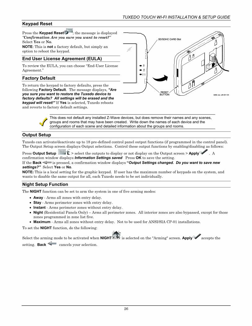
TUXEDO TOUCH WI-FI INSTALLATION & SETUP GUIDE
26
Keypad Reset
Press the Keypad Reset ; the message is displayed “Confirmation Are you sure you want to reset?” Select Yes or No. NOTE: This is not a factory default, but simply an option to reboot the keypad.
End User License Agreement (EULA) To review the EULA, you can choose “End-User License Agreement.”
Factory Default To return the keypad to factory defaults, press the following Factory Default. The message displays, “Are you sure you want to restore the Tuxedo device to factory defaults? All settings will be erased and the keypad will reset!” If Yes is selected, Tuxedo reboots and reverts to factory default settings.
This does not default any installed Z-Wave devices, but does remove their names and any scenes, groups and rooms that may have been created. Write down the names of each device and the configuration of each scene and detailed information about the groups and rooms.
Output Setup Tuxedo can activate/deactivate up to 18 pre-defined control panel output functions (if programmed in the control panel). The Output Setup screen displays Output selections. Control these output functions by enabling/disabling as follows:
Press Output Setup > select the outputs to display or not display on the Output screen > Apply . A confirmation window displays Information Settings saved Press OK to save the setting. If the Back is pressed, a confirmation window displays “Output Settings changed. Do you want to save new settings?” Select Yes or No. NOTE: This is a local setting for the graphic keypad. If user has the maximum number of keypads on the system, and wants to disable the same output for all, each Tuxedo needs to be set individually.
Night Setup Function The NIGHT function can be set to arm the system in one of five arming modes:
• Away - Arms all zones with entry delay. • Stay - Arms perimeter zones with entry delay. • Instant - Arms perimeter zones without entry delay. • Night (Residential Panels Only) – Arms all perimeter zones. All interior zones are also bypassed, except for those
zones programmed in zone list five. • Maximum - Arms all zones without entry delay. Not to be used for ANSI/SIA CP-01 installations.
To set the NIGHT function, do the following:
Select the arming mode to be activated when NIGHT is selected on the "Arming" screen. Apply accepts the setting. Back cancels your selection.

TUXEDO TOUCH WI-FI INSTALLATION & SETUP GUIDE
27
Power Mode Setup Power Mode allows you to reduce power consumption in the event of a system trouble such as AC Loss or Panel Low Battery. Select Power Save Mode to enable; then choose Turn-off Network, or Override Display Settings.
Press Apply to save settings.
AC Loss Notes When Override Display Settings is selected, Display settings are overwritten and Tuxedo operates in low power mode:
• Brightness/Volume controls decrease to minimum levels. • Return to Homepage After time resets to 30 seconds. • Auto Slideshow After time reverts to Never. • When AC power is restored, the original Display settings resume. • The device will disable the Network if it is configured. • AC loss changes are not supported in safe mode.
Multimedia
Picture & Slide Show Setup Tuxedo can display personal photo(s) on the Home screen as wallpaper or in a slide show format. To set up a slide show of pictures, do the following: 1. Insert your personal media (SD/SDHC) card (with stored picture files). Formats supported are .bmp, .png or .jpg files.
2. From the Home screen, press Multi-Media > Picture . The first image is displayed and a list of stored images appears on the screen.
Slide Show Setup
1. To add an image to the slide show, select the image from the list and press Add Image ; the image appears on the screen and a check mark appears next to the selected image name on the list.
2. Press Slide Delay arrow to select the time interval that you want to allow between each photo being viewed. Choose from (5, 10, 15, or 20 seconds).
3. Press Transition arrow to select the type of viewing transition desired (Standard, Horizontal, Vertical or Fade Out).
4. After images have been added, press Play Image to begin the slide show.
To remove an image from the slide show, select the image, and press Deselect Image .
5. To navigate to the Next Image press ; to go back to a Previous Image press .
New Wallpaper Setup 1. Use the slide bar to highlight the file (image) you want to be displayed on the keypad screen. 2. Press Set Wallpaper ; view your selection from the “Home” screen.
Press TOP to move up one level in the directory. Press OPEN to view larger images and/or open directories, select from the list of images.
Press CLEAR ALL to clear all pictures from the current slide show rotation. NOTES • To exit the slide sho at any time and resume normal operation, press anywhere on the screen. • When an image is loading, no other Picture Setup function can be performed.
UL Multimedia functionality is supplementary on and has not been evaluated for UL compliant applications.

TUXEDO TOUCH WI-FI INSTALLATION & SETUP GUIDE
28
Camera Options and Setup
The access the camera setupage press Multimedia > Camera View/Record > Camera Setup . NOTES: • Keypad must be connected to same LAN or Wi-Fi network as the cameras, before they can connect. • View the “IP Camera Setup” training video for helpful information to aid in the setup. • Supports up to 32 cameras with up to four cameras viewable at one time. NOTES:
• QuickTime® media player must be installed on your PC. • Camera viewing is compatible with IE8 (and above) and Safari 5.0 (and above); and not compatible with Opera
web browsers or Chrome version 42 or above. • Some older versions of these cameras may need a firmware upgrade; see separate instructions. • The cameras will appear in a Quad View mode, however, you can select icon in bottom right corner for single view.
Icon Name Description
Camera Discovery Discovers all cameras with UPNP Enable
Add Camera Manually add a camera
Edit Camera Edit existing camera
Delete Delete a selected camera
Delete All Delete all camera’s
Camera Settings Review the camera’s current setting
Camera Wi-Fi Changes the selected camera from LAN to Wi-Fi
Recording Settings Adjust the recording settings for each camera
First Time Setup Scan and configure the cameras prior to mounting; follow the steps below:
1. Connect an Ethernet cable to the back of your camera (LAN); connect the opposite end to the Ethernet Port on your router (or HONEYWELL-WAP, as long as it is connected to the router). Apply power to the Camera. Wait 60 seconds for initial power-up of camera. NOTE: A LAN connection is initially required, once the camera is configured with the Camera WIFI option it will change if from a LAN to Wi-Fi connection.
2. Press Discover to locate cameras. The screen displays: “Discovering Cameras Please Wait…” Repeat this step until all cameras are discovered.
Notes: • All devices enabled for UPNP (Universal Plug and Play) will be discovered. • Delete the unwanted devices.
The Tuxedo will do a 24-hour refresh (to make sure the IP address has not changed.) The deleted devices will not populate again during the 24-hour refresh.
• If new cameras will not discover, you can manually enter or wait for the 24-hour refresh.
3. To edit information, highlight the camera name and press Edit . Highlight each field and enter the required information (see Add/Edit Options below), and then press Save .
To retrieve camera settings and connect to the camera, press Connect .
Use the web browser to view cameras for non-security purposes only. Camera streams viewed from the web browser can stop without indication due to network connection issues.

TUXEDO TOUCH WI-FI INSTALLATION & SETUP GUIDE
29
Add/Edit Options If the camera information is not discovered automatically, press Add to enter information on the “Add New Camera” screen.
Name Description NOTE: Must be alphanumeric only, no special characters (including space) are compatible.
Camera Name Default is the Camera Model (abbreviated) X, where X= The Mac NOTE: Maximum # of cameras supported.
Camera IP Address This is the address of the camera, which is assigned by the router
MJPEG Streaming URL Fixed RTSP (Real Time Streaming Protocol) Port #. Select ports (554, (1024-
65534)) Resolution (Options are 160x120, 320x240, 640x480)
Select from 160 x 120, 320 x 240 or 640 x 480. For best performance set video resolution to 320 x 240, 8 frames per sec.
NOTE: • Model iPCAM-WL resolution is fixed at 320 x 240 or user can
change to 640x480. • When setting the resolution to 640 x 480, the recommended
frame rate is eight frames per sec. When setting the resolution to 320 x 240, the recommended frame rate is no more than 15 frames pre sec.]
Camera Model: Select iPCAM-WI, iPCAM-WI2, iPCAM-WI2B (black), iPCAM-WO or iPCAM-PT, WVC210, iPCAM-ACU, iPCAM-WL, ONVIF, Trendnet, and others. NOTE: Only the Honeywell/AlarmNet IP cameras will work with Total Connect Remote Services. Refer to HTTPS://mywebtech.honeywell.com or www.tuxedotouchtoolkit.com for the “Camera Compatibility” documentation.
RTSP Streaming URL Real Time Streaming Protocol, if using a Non-AlarmNet IP camera, this information will be retrieved from the camera or the cameras interface page
Mobile Streaming URL Fixed HTTP Port Default value = 80. To change enter valid port number (80
(1024-65534)). NOTE: Do not use ports 6665-6669 for camera HTTP configuration. These ports block MPEG streaming and PT commands of Safari based PC and mobile devices
Frame Rate Options are 1, 2, 3, 4, 5, 6, 8, 10, 15, 20, 25, or 30. User Name/Password Administrative password to access the camera’s setup or
viewing page. NOTE: Every camera manufacturer makes their cameras slightly different, so Honeywell does not guarantee that Tuxedo will work with every camera that supports the above network and codec features.
If using Total Connect, press Total Connect to reset the camera for remote viewing. This programs the camera to default for Total Connect compatibility. A pop-up window displays: “For remote camera viewing service, please contact your alarm company and ask for Total ConnectTM service and provide the camera’s MAC ID XX:XX:XX:XX:XX:XX. Press continue to prepare the camera for Total Connect service.” Press CONTINUE or CANCEL. Pressing Continue provides a confirmation window, which displays: “Do you want to reset the Camera?” Yes or No. See Remote Access section, later in this document. Press Save when done. Use Refresh to update the screen, if necessary.

TUXEDO TOUCH WI-FI INSTALLATION & SETUP GUIDE
30
Setting the Camera’s Wi-Fi If the camera is configured as a LAN connection, and the final installation location is only accessible wirelessly, the Camera WIFI option will allow you to assign the camera to the Wi-Fi network. After all cameras have been added, press Camera WIFI to enter the camera wireless settings information from your router. The screen displays: “INFO: Camera Wi-Fi setup is applicable only for discovered cameras.”
1. Enter the appropriate wireless information: • SSID: ANY • Security Mode: Disabled, WPA personal, WPA2 personal, or WEP • Network Type: Infrastructure • Domain: USA • Channel: Auto
1. For Security Mode, enter the appropriate information: • Tx Key: 1, 2, 3 or 4; WEP Encryption: 64 bit Key (10 Hex Chars) or 128 bit Key (26 Hex Chars) , WPA and
WPA2. • Authentication: Open System or Shared Key • Passphrase: press GENERATE • Key: must consist of 10 hexadecimal characters
2. Press Apply to All to set cameras for wireless operation. Press Save when done. A pop-up window displays: “Info
XXX.XXX.X.X WIFI Configuration Saved.” 3. Remove the LAN cable and reboot the camera. Once rebooted, verify the can be viewed wirelessly via the Tuxedo.
If the camera does not have wireless capability, leave the camera connected to the router via the LAN connection.
4. Press Camera Settings to enter Video, Network, Wireless, and Other settings, if required; refer to Advanced Camera Settings below. NOTE: Cameras must be enrolled to access the Settings screen. If multiple cameras are enrolled, highlight the desired camera to make changes.
Advanced Camera Settings All features below can be changed based on the settings required. Press Camera Settings to access the following settings. NOTES:
• Press Save! after each selection • Fixed Quality is not an option on the Camera Settings home screen.
Video Feature MPEG-4, MJPEG and H.264 Settings Resolution 160x120, 320x240, 640X480 Fixed Quality Very Low, Low, Normal, High, Very High Max Frame Rate 1-8, 10, 15, 20, 25, 30
Network Feature Options
Internet Connection Type Dynamic or Static IP IP Address, Subnet Mask, Default Gateway
Network settings (usually settings for setting up for static or a DHCP reservation list)
UPNP Enables the discovery option in the camera when the Discover is pressed
HTTP Port Options are 80, 1024-65534 RTSP Port Real Time Streaming Protocol Port (default is 554)
Wireless Feature Options
SSID Network Name Security System Disabled, WPA Personal, WPA2 Personal Passphrase/ SharedKey Password N/W Type Ad-hoc or Infrastructure Domain USA Channel Auto

TUXEDO TOUCH WI-FI INSTALLATION & SETUP GUIDE
31
Others Feature Description and Options
Reset to Default Factory defaults the Camera A pop window displays: “Do you want to reset the Camera” select Yes or No
Restart Camera Provides a reboot of the camera
Camera functionality is supplementary only and has not been evaluated for agency compliant installations.
Removing Cameras 1. To delete a camera, highlight the camera name and press DELETE. A confirmation window displays “Do you
want to delete “the selected” camera? Yes or No. If Yes is selected, a message Select Yes to permanently remove the camera name device from the list. Note: select delete all then select discover to rediscover all devices” appears.
2. To delete all cameras, press DELETE ALL. A confirmation window displays “Do you want to delete all cameras?” Yes or No.
NOTE: If any single camera is removed, all cameras must be removed before that camera can be re-added to the camera list. This is done by performing a Camera Discovery.
Viewing Cameras Cameras can be viewed locally from the Tuxedo keypad. NOTE: To setup and view cameras for use with Wi-Fi enabled devices and Total Connect, refer to the Remote Access section later in this document.
Camera Icons
Camera Settings Play Auto Pan Quad View Full View Pan/Tilt Connect Reset Record Recording Settings
To view cameras locally, do the following:
1. Press Multi-Media > Camera View/Record . 2. Highlight the View Cameras button; images from installed cameras appear. 3. Use the Quad View button to view up to four cameras on the same screen. 4. Select a quadrant area on the screen and then select the camera that you want to appear in that quadrant.
NOTES: • For pan/tilt style cameras, use Pan/Tilt to change the angle of the selected camera. • Camera Play/Pause functionality is not supported from the web access. • If the resolution is greater than 320X240, the keypad will crop it to 320X240.
Video Recording & Event Viewing The camera Recording feature allows you to create a scene that records two minutes of video events onto the SD card. The first 15 seconds records the pre-event and the remaining time records the post-event. Up to four simultaneous video events can be recorded and the first four supported cameras will be associated (automatically) to the recording. An SD card is required to store the recordings.
For proper recording, use the following camera settings for the resolution and frame rate: • 640X480, less than 5 frames per second • 320X240, less than 8 frames per second
Critical Events This option is enabled in the Creating Scenes section. When this option is enabled, a maximum of two events are recorded even when the SD card is not available. If more than two critical events occur, then the older one is replaced by the latest event.
Video recording is for lifestyle and awareness purpose only. Using this feature for life safety, person and property protection should be prohibited. It is not certified for any agency compliant installations, because it may fail at any time without any notice.

TUXEDO TOUCH WI-FI INSTALLATION & SETUP GUIDE
32
To access the recording feature:
1. Press Camera View/Record > Camera Setup > Camera Settings . To change the settings for resolution, fixed quality and frame rate, see the Camera Add/Edit section.
NOTES: • The recommended frame rate is eight frames per sec, when setting the resolution to 640 x 480. • The recommended frame rate is no more than 15 frames per second, when setting the resolution to 320 x 240. • To get a 2-minute recording the Frames Per Second should be 5 frames or less
2. Press Save when done. This will return you to the Camera Setup Management screen.
3. Press Recording Settings and select a camera to assign to “Recording Cam 1-4” from the drop down list. NOTE: This is where the camera is assigned when Creating a Scene to activate a camera on an event.
4. Press Save when done.
Manual Video Recording The camera-recording feature can also be used manually to record events to an SD Card (supplied).
To access the manual video recording feature, press Camera Record on the camera view screen.
Select the desired camera for recording and then press Record to begin recording.
Press Record again to stop the recording. NOTE: The maximum recording duration is two minutes.
Using Third Party Cameras The Tuxedo keypad can support cameras by multiple manufacturers. For a complete list visit https://mywebtech.honeywell.com/ or www.tuxedotouchtoolkit.com and refer to the IP Camera Compatibility List for supported cameras.
General Notes: • A maximum of four cameras can be enabled for remote viewing with the same account activation. If more than four
cameras are needed for remote viewing, user can use manual port forwarding in router. For manual port forwarding, the recommended internal port configuration is 80 for HTTP and 443 for HTTPS.
• Cameras can be enabled or disabled from the Tuxedo Camera Setup screen for remote viewing. • Using the Multimedia camera view, and other web pages, there are the chances that the session could timeout and the
connection with Tuxedo web server will be terminated. In this case, the top bar status updates and all other status updates from Tuxedo will fail. It is advised to refresh the page and continue using the web application.
Event Viewing
To view a cameras’ recorded event:
1. Press Multimedia > Event View ; the list of events appears on the screen.
2. Press Event View Setup and select the Filter by Camera button to view a specific cameras’ event, select Show All to view all camera events or select Filter By Critical to view (if enabled) a maximum of two events that have been stored, when the SD card is not available.
3. Press Save when done. 4. Highlight the event from the list to view, and press Play .
5. Use Delete to remove the event video.
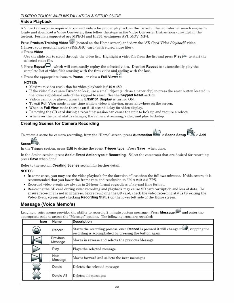
TUXEDO TOUCH WI-FI INSTALLATION & SETUP GUIDE
33
Video Playback A Video Converter is required to convert videos for proper playback on the Tuxedo. Use an Internet search engine to locate and download a Video Converter, then follow the steps in the Video Converter Instructions (provided in the carton). Formats supported are MPEG4 and H.264, containers AVI, MOV, MP4.
Press Product/Training Video (located on the Home screen) and view the “SD Card Video Playback” video. 1. Insert your personal media (SD/SDHC) card (with stored video files). 2. Press Video.
Use the slide bar to scroll through the video list. Highlight a video file from the list and press Play to start the selected video file.
3. Press Repeat , which will continually replay the selected video. Deselect Repeat to automatically play the complete list of video files starting with the first video and ending with the last.
4. Press the appropriate icons to Pause , or view a Full View . NOTES: • Maximum video resolution for video playback is 640 x 480. • If the video file causes Tuxedo to lock, use a small object (such as a paper clip) to press the reset button located in
the lower right-hand side of the keypad to reset. See the Keypad Reset section. • Videos cannot be played when the EN50131 Display is turned ON. • To exit Full View mode at any time while a video is playing, press anywhere on the screen. • When in Full View mode there is an 8-10 second delay for video display. • Removing the SD card during a recording session can cause the unit to lock up and require a reboot. • Whenever the panel status changes, the camera streaming, video, and play backstop.
Creating Scenes for Camera Recording
To create a scene for camera recording, from the “Home” screen, press Automation > Scene Setup > Add
Scene . In the Trigger section, press Edit to define the event Trigger type. Press Save when done.
In the Action section, press Add > Event Action type > Recording. Select the camera(s) that are desired for recording; press Save when done.
Refer to the section Creating Scenes section for further detail. NOTES: • In some cases, you may see the video playback for the duration of less than the full two minutes. If this occurs, it is
recommended that you lower the frame rate and resolution to 320 x 240 @ 5 FPS. • Recorded video events are always in 24-hour format regardless of keypad time format. • Removing the SD card during video recording and playback may cause SD card corruption and loss of data. To
ensure recording is not in progress, before removing the SD card, check the video recording status by exiting the Video Event screen and checking Recording Status on the lower left side of the Home screen.
Message (Voice Memo’s) Leaving a voice memo provides the ability to record a 2-minute custom message. Press Message and enter the appropriate code to access the “Message” options. The following icons are revealed:
Icon Name Description
Record Starts the recording process, once Record is pressed it will change to , stopping the
recording is accomplished by pressing the button again.
Previous Message Moves in reverse and selects the previous Message
Play Plays the selected message
Next Message Moves forward and selects the next messages
Delete Deletes the selected message
Delete All Deletes all messages

TUXEDO TOUCH WI-FI INSTALLATION & SETUP GUIDE
34
Recording a Message
1. Press RECORD and record your message while staying within approximately one foot of the keypad and speaking at a normal voice volume. As you are recording your message, the remaining time counter counts down to indicate the total remaining time available and a “Recording New Memo…” message is displayed above the message list window.
2. Press STOP when you are done recording the message. NOTE: Upon completion of the recording the Message LED will flash.
Listening to a New Message To listen to a voice message: 1. Highlight the message and then press PLAY . As the message is being played, a “Play (#): Voice Memo…” message
is displayed above the message list window. The Message LED continues to flash until all new messages have been played back entirely. When the end of the message is reached, the playback stops.
2. To listen to the next message or previous message, press NEXT and PREV . NOTE: The message LED will stop flashing when all messages have been heard.
Deleting Message(s)
To delete the selected message, press DELETE . A confirmation window is displayed stating: Del Selected
Selected Memo 2: 11/02/12 00:30:00 Select Yes or No.
To delete all messages, press DELETE ALL . A confirmation window is displayed stating: “Confirmation”
Do you want to delete all messages? Select Yes or No.
To exit, press Back > Home . Notes:
• Each message is numbered, dated and the length of the message in seconds (Sec) is displayed on the message list. • Use the slide bar to raise and lower the message volume.

TUXEDO TOUCH WI-FI INSTALLATION & SETUP GUIDE
35
Z-Wave Setup Before a Z-Wave device will work in the home control network, it must be added (also called included) into the network. View the Programming of Z-Wave Devices training video and follow the instructions below to add and control devices in a home control network.
EXISTING NETWORK NOTE: Z-Wave products from other manufacturers can be included (added) into the Tuxedo network at any time. Z-Wave devices that are always powered can serve as repeaters regardless of manufacturer
WARNING: Automation is intended for lifestyle convenience. Do not use automation for life safety and property protection.
Agency compliant installations application notes: • Automation functionality is supplementary only and has not been evaluated. • Z-Wave applications have not been evaluated. • Access control functionality has not been evaluated and may not be used.
The Z-Wave setup is accessed by pressing Automation then Z-Wave Setup . Below is a list of the icons that will appear:
Z-Wave Device List Icons
Room Setup
Scene Setup
Z-Wave Setup
Group Setup
Refresh
Output Setup
Z-Wave device Management Screen Device List
The “Z-Wave Device Management Screen Device List” is composed of 5 columns. DEVID Displays the device or “Node” ID displayed in numerical order as you “Include” or “Add” Devices
NOTE: Once a device is excluded, that node number cannot be used again, unless the controller is defaulted.
NAME Displays default and custom device names TYPE Displays the Z-Wave device type (i.e. multilevel switch, binary switch, entry controller, etc.) INFO Displays the following Icons:
Router: Chain Link: Pad Lock:
The device is a routing slave and can be used as a repeater.
The node (device) can send unsolicited messages to the Tuxedo.
Secured Network Supported
STATUS Displays the following messages: Success Network The node has reported a normal status report. Failed Communication with this device has been lost. Update Success Search was successful when running “Search Devices” operation on a
device. Update Failed Search was unsuccessful when running “Search Devices” operation on a
device. Not in Secure Network Device is expected to be secured (such as an entry controller, but failed
to receive the encrypted key. (Remove device and add again closer to the Tuxedo.)
Up Date Timed Out This message appears when a device does not respond when requested during a “Scan Network” is performed.

TUXEDO TOUCH WI-FI INSTALLATION & SETUP GUIDE
36
Z-Wave Device Management Buttons Defined
Add Device This icon is for including or adding a new device to the network. NOTE: Refer to the devices
installation instructions for the Add and Remove procedure.
Remove Device
This icon is for removing, or excluding, a device from the devices current network. However, the device does not have to be on the same network. NOTE: Refer to the devices installation instructions for the Add and Remove procedure.
Abort operation Pressing the Abort button cancels the “Z-Wave Add Device” or “Remove Device” operation.
Remove Failed If a device, or node, is no longer operational, or will not remove by using the “Remove
Device” operation, it will remove the device from the list.
Device Setup Editing the device is for changing the defaulted name to a custom descriptor chosen by the
installer or end user NOTE: This is also the location for changing the icon.
Search Device
If a device is no longer functional, this option allows you to press the desired device, press Search Device and the Tuxedo will scan the network for the device. If successful, the device route will be updated. If failed, then the device was not found by the Tuxedo.
Scan Network
The “Scan Network” operation rebuilds the entire Z-Wave network by determining the best route for each device and updating the network routing table. This is designed to improve Z-Wave network’s performance. Also known as Z-Wave “Network Rediscovery.”
Z-Wave Reset The ability to reset the Z-Wave controller without resetting the Tuxedo, it power cycles the
internal Z-Wave card.
Z-Wave Default
Press the icon to request a new network ID, or remove all the existing devices. (Note: This does NOTE remove each device. Once defaulted, you must use the remove device operation on each device. If this operation is not completed the device cannot be included into the new network.
Primary
Controller
This icon will display the current role of the controller. If the device displays a “P,” it is the primary controller and can add and remove devices. If the device displays an “S” it is a secondary controller and is only there to display and control devices. Example, if used in conjunction with an additional Tuxedo keypad and experiencing network performance issues, the Tuxedo can be used to extend the network by programming it in as a secondary controller to the Tuxedo’s network. It cannot add and remove devices.
Secondary Controller
Adding and Deleting Z-Wave Devices Adding and Deleting Z-Wave devices on the Tuxedo keypad depends on the button pressed. For adding a device press
Add Device , for removing devices press Remove Device . In each situation, refer to the installation instructions on the Z-Wave device for the proper procedure for adding and removing from the Z-Wave network.
Add a Light, Switch or Outlet Module 1. Install device according to the manufacturer’s directions.
2. Press Add Device . 3. Power the switch on and verify the device module is ON. Press Function Key and follow the on-screen messages
until Device added successfully is made. NOTES: If a dimmer module was added a slide bar (to control the dimmer) displays. If an on/off light, appliance, switch or outlet module was added, an On/Off button (to control the device) displays.
Add a Door Lock 1. Assemble the Z-Wave door lock according to the manufacturer’s directions. Be sure the door lock
orientation/handedness is correct. 2. Refer to the Door Lock Instructions and connect necessary cables, then install batteries. 3. Enroll the door lock (refer to the Door Lock’s Instructions Guide for procedure.)
4. Press Add Device .

TUXEDO TOUCH WI-FI INSTALLATION & SETUP GUIDE
37
NOTE: Locks with older firmware require enrollment within 10’ of the lock. Newer locks, with updated firmware, do not require this limitation. Refer to the manufacturer of the lock for more information. If the lock will not enroll, try adding a device in between the keypad and the lock. If that does not work, bring the lock closer to the keypad to enroll.
5. Follow the on-screen messages until “Device added successfully.” 6. To verify activation on the Tuxedo, click Back; wait 30 seconds. Click Refresh; the new device is displayed.
NOTES: • Tuxedo has the capability to monitor status of lock and determine whether locked, unlocked, and low battery. • If the lock is not working, verify the lock is still in a Secure Network, if so rescan for devices. If the lock says
Not in Secure Network, it must be deleted and re-enrolled in the Tuxedo. • Some manufacturers will not transmit status during a low battery condition.
The Tuxedo will NOT push the user codes to the lock. Therefore, any user code in the panel can be used in the lock, but has to be separately programmed in the lock itself. Refer to the locks installation instruction for programming instructions.
Add a Garage Door Controller 1. Assemble the Z-Wave Garage Door Controller according to the manufacturer’s directions. 2. Refer to the Garage Door Controllers instructions and connect necessary cables and for the Z-Wave Add/Remove
procedure.
3. Press Z-Wave Add Device . 4. Follow the on-screen messages until “Device added successfully.” 5. To verify activation on the Tuxedo, click Back; wait 30 seconds. Click Refresh; the new device is displayed.
Do not use any garage door automation with any garage door opener that lacks the safety features required by U.S. federal safety standards (this includes any garage door opener model manufactured before January 1, 1993). A garage door opener that cannot detect an object, stop, and reverse the door – does not meet current U.S. federal safety standards. Your garage door opener also must signal before unattended door operation. For more information, please consult your garage door opener manual.
Add a Water Valve
1. Assemble the Z-Wave Water Valve according to the manufacturer’s directions. 2. Refer to the Water Valve Instructions and connect necessary cables and water pipe fittings. Also, review the
procedure for the Z-Wave Add/Remove procedure.
3. Press Z-Wave Add Device . 4. Follow the on-screen messages until Device added successfully. 5. To verify activation on the Tuxedo, click Back; wait 30 seconds. Click Refresh; the new device is displayed.
Add a Honeywell Thermostat 1. Install thermostat according to the manufactures instructions. Device should be mounted in the final location
and tested before adding it to the system.
2. Press Z-Wave Add Device . 3. On the Honeywell thermostat select Thermostat; set the “Time/Date” and follow the instructions in the
thermostat Installation Guide for “Z-Wave enrollment/inclusion.” 4. Wait a few seconds for the enrollment to finish and the on-screen message “Device added successfully” appears. 5. To complete, press Done on the thermostat. 6. Press Exit to return to normal operation. 7. To verify activation: on Tuxedo, press back ; wait 30 seconds. Press Refresh ; the new device is
displayed. NOTES: • If not using a Honeywell thermostat, enrollment procedure may vary. Refer to the Thermostat instructions. • Some thermostats do not update temperature status automatically (i.e., Wayne Dalton). • If you change the thermostat temperature and immediately go to the thermostat screen, the values are shown
as zero because the status has not updated the controller. • Some thermostats may not provide all the options, which are provided/shown in Tuxedo. If any operation,
which is not being supported by the thermostat, is executed from the tuxedo, the thermostat will just ignore the request.

TUXEDO TOUCH WI-FI INSTALLATION & SETUP GUIDE
38
• Radio Thermostat CT100 will not transmit the Celsius scale to the Tuxedo keypad, so it will only work in Fahrenheit mode.
• Intouch Thermostats will not send status during a low battery condition.
Honeywell is not responsible for property damages due to improper wiring and setting of the thermostat modes.
Z-Wave Device Setup
Changing the Name To change the Z-Wave device icons, do the following:
1. Press Automation > Z-Wave Setup to display the “Z-Wave Device Management” screen. 2. Press Z-Wave device to be edited. 3. Press on the text box, which will produce a keypad, allowing you to edit the name. Press, “Go” when finished
saving the name.
Changing the Icon
To change the Z-Wave device icons, do the following: 1. Press the Z-Wave device to be edited. 2. Beneath device name, select the icon to represent the switch.
NOTES: • This applies to Binary (On/Off), Multilevel (Dimming) switches and Water Valves. • This is a local change only; the icons do not synchronize with Total Connect. • The FortrezZ® and Leak Gopher® Water valve learn in as a Water Faucet icon by default, but is changeable.
All other water valves may learn in as a binary switch. • All Water Valve commands are excluded from the “All Switches On/Off” command by default. • Changing binary switch to Water Valve also excludes it from the “All Switches On/Off” command.
Device Icon Options
Light Bulb
Light
Switch
Garage
Door
Sprinkler
Pool
Water Faucet
Strobe
Window
Siren
Sounder
Fan
Secondary Tuxedo Note Any device assigned to a water valve icon on the primary Tuxedo must be assigned to the same device on the secondary Tuxedo. Failure to do so results in the water valve responding to the “All Switches On/Off command.”
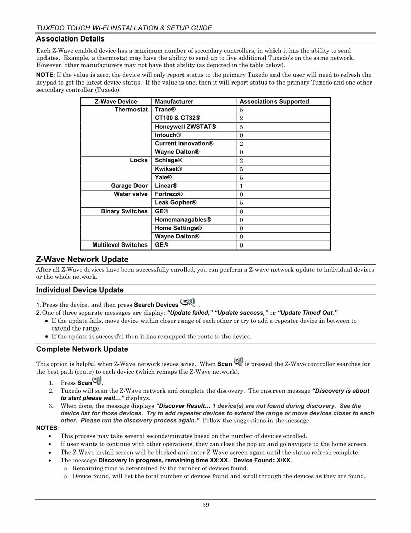
TUXEDO TOUCH WI-FI INSTALLATION & SETUP GUIDE
39
Association Details Each Z-Wave enabled device has a maximum number of secondary controllers, in which it has the ability to send updates. Example, a thermostat may have the ability to send up to five additional Tuxedo’s on the same network. However, other manufacturers may not have that ability (as depicted in the table below). NOTE: If the value is zero, the device will only report status to the primary Tuxedo and the user will need to refresh the keypad to get the latest device status. If the value is one, then it will report status to the primary Tuxedo and one other secondary controller (Tuxedo).
Z-Wave Device Manufacturer Associations Supported Thermostat Trane® 5
CT100 & CT32® 2 Honeywell ZWSTAT® 5 Intouch® 0 Current innovation® 2 Wayne Dalton® 0
Locks Schlage® 2 Kwikset® 5 Yale® 5
Garage Door Linear® 1 Water valve Fortrezz® 0
Leak Gopher® 5 Binary Switches GE® 0
Homemanagables® 0 Home Settings® 0 Wayne Dalton® 0
Multilevel Switches GE® 0
Z-Wave Network Update After all Z-Wave devices have been successfully enrolled, you can perform a Z-wave network update to individual devices or the whole network.
Individual Device Update
1. Press the device, and then press Search Devices . 2. One of three separate messages are display: “Update failed,” “Update success,” or “Update Timed Out.”
• If the update fails, move device within closer range of each other or try to add a repeater device in between to extend the range.
• If the update is successful then it has remapped the route to the device.
Complete Network Update
This option is helpful when Z-Wave network issues arise. When Scan is pressed the Z-Wave controller searches for the best path (route) to each device (which remaps the Z-Wave network).
1. Press Scan . 2. Tuxedo will scan the Z-Wave network and complete the discovery. The onscreen message “Discovery is about
to start please wait…” displays. 3. When done, the message displays “Discover Result… 1 device(s) are not found during discovery. See the
device list for those devices. Try to add repeater devices to extend the range or move devices closer to each other. Please run the discovery process again.” Follow the suggestions in the message.
NOTES: • This process may take several seconds/minutes based on the number of devices enrolled. • If user wants to continue with other operations, they can close the pop up and go navigate to the home screen. • The Z-Wave install screen will be blocked and enter Z-Wave screen again until the status refresh complete. • The message Discovery in progress, remaining time XX:XX. Device Found: X/XX.
o Remaining time is determined by the number of devices found. o Device found, will list the total number of devices found and scroll through the devices as they are found.

TUXEDO TOUCH WI-FI INSTALLATION & SETUP GUIDE
40
Creating Scenes The system can automatically activate devices when certain triggered events occur. When a programmed trigger/condition occurs, the defined device(s) activates. The programming of these triggers and actions is called Scenes. A scene consists of a trigger, an optional condition, and up to five actions. Up to 30 local (20 more using Total Connect Remote Services) scenes can be defined. Scenes must have at least one trigger and one action to initiate. Remote scenes are viewable from the keypad. However, they can only be viewed; editing is done through Total Connect.
The user can access scenes by pressing Automation > Scene Setup . The screen will display a table.
Column Description SI.No Represents the scene number. Name Names assigned to the scene.
Status Enabled or Disabled. This allows the option to enable or disable the scene for occasions the scene is not desired.
Manual Run
Gives you the option to run the scene manually to verify its functionality. Also used for testing the scene on initial setup to confirm all actions are taking place.
The other options are:
Name Description Local Lists all of the scenes programmed locally in the keypad
Remote Lists all of the scenes programmed through Total Connect Remote Services. These scenes cannot be edited, only viewed for their settings. The only option to edit is through Total Connect.
Press to add a new scene.
Press to remove an existing scene.
Press to edit an existing scene.

TUXEDO TOUCH WI-FI INSTALLATION & SETUP GUIDE
41
Defining Scenes The system can automatically activate various devices when certain events occur based on predefined Scenes.
Trigger Defines the event that triggers the programmed action(s). Triggers include the following categories:
Time Security Thermostat Door Garage Door Water Valve Zones
Condition Defines an optional event that puts a condition on the trigger. If a condition is set, the condition must exist at the time of the trigger for the action to occur. Conditions include the same categories as triggers. However, conditions cannot be set with the same category as the trigger. (ex., if setting a trigger event for security, you cannot use security as a condition).
Action Defines the desired device action when the trigger event occurs. Actions include the following categories:
Security Light Thermostat Door Garage Door Water Valve Recording E-Mail
1. Press Add Scene . 2. Press Scene Name; enter a name. 3. Assign the desired Condition, Trigger, and Action for this Scene, See Scene Options section for detailed
information. NOTES:
• After each selection click Save! • Scenes cannot be triggered using panic zones 995, 996 and 999 on commercial panels and panic zones 95, 96
and 99 on residential panels. • A scene consists of a trigger, an optional condition, and up to five actions.
Example: You want the lights to turn on when you arrive home and disarm the system, but only at night.
• Trigger: “when the system disarms” > Set the Trigger to Security: System Disarm. • Condition: “only at night” > Set the TIME condition (enter the Start Time and Duration) • Action: “Turn the lights ON” Set the Action to LIGHT: ON.
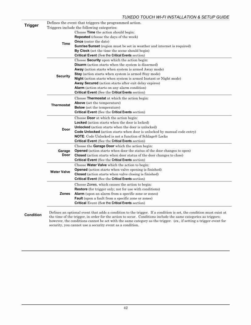
TUXEDO TOUCH WI-FI INSTALLATION & SETUP GUIDE
42
Trigger Condition
Defines the event that triggers the programmed action. Triggers include the following categories:
Time
Choose Time the action should begin: Repeated (choose the days of the week) Once (enter the date) Sunrise/Sunset (region must be set in weather and internet is required) By Clock (set the time the scene should begin) Critical Event (See the Critical Events section)
Security
Choose Security upon which the action begin: Disarm (action starts when the system is disarmed) Away (action starts when system is armed Away mode) Stay (action starts when system is armed Stay mode) Night (action starts when system is armed Instant or Night mode) Away Secured (action starts after exit delay expires) Alarm (action starts on any alarm condition) Critical Event (See the Critical Events section)
Thermostat
Choose Thermostat at which the action begin: Above (set the temperature) Below (set the temperature) Critical Event (See the Critical Events section)
Door
Choose Door at which the action begin: Locked (action starts when the door is locked) Unlocked (action starts when the door is unlocked) Code Unlocked (action starts when door is unlocked by manual code entry) NOTE: Code Unlocked is not a function of Schlage® Locks Critical Event (See the Critical Events section)
Garage Door
Choose the Garage Door which the action begin: Opened (action starts when door the status of the door changes to open) Closed (action starts when door status of the door changes to close) Critical Event (See the Critical Events section)
Water Valve
Choose Water Valve which the action to begin: Opened (action starts when valve opening is finished) Closed (action starts when valve closing is finished) Critical Event (See the Critical Events section)
Zones
Choose Zones, which causes the action to begin: Restore (for trigger only; not for use with conditions) Alarm (upon an alarm from a specific zone or zones) Fault (upon a fault from a specific zone or zones) Critical Event (See the Critical Events section)
Defines an optional event that adds a condition to the trigger. If a condition is set, the condition must exist at the time of the trigger, in order for the action to occur. Conditions include the same categories as triggers; however, the conditions cannot be set with the same category as the trigger. (ex., if setting a trigger event for security, you cannot use a security event as a condition.

TUXEDO TOUCH WI-FI INSTALLATION & SETUP GUIDE
43
Scene Setup Options
Action
Defines the desired device action(s) when the trigger event occurs. Actions include the following categories:
Security
Disarm Away Stay Night (Arms Instant) Disarm with Code Enter User Code
NOTE: A valid user code is required for the system to perform any of the actions listed. Enter the code at the prompt. If the user code is later deleted from the security system, you will need to reenter a valid code at this screen.
Light Choose the light option to occur upon the trigger event: On/Off (Multi-Level switches will provide a slide bar.) On for Time
Thermostat
Off Heat Cool Set Mode Set Point
Set energy mode (normal/savings); if savings selected, see your local programming of the thermostat for settings
Door Unlocks Locks
Garage Door Open Close
Water Valve Open Close
Recording
Select the camera to start recording after the selected trigger. Warning: Video recording is for lifestyle and awareness purpose only. Using this feature for life safety, person and property protection should be prohibited. Video recording is no applicable for agency compliant applications. Due to a number of “onsite” variables the recording may fail at any time without notice. NOTE: If the SD card is full and a manual scene is executed, a message stating, “SD card is full" will not display and the event will not record.
Select the Email Recipient(s) to receive a custom message, based on the triggered event. Configure E-Mail Id’s: This option allows the assignment of 4 email addresses to the selected action. Enable the SMTP port settings and SSL option must be enabled for the email feature to operate. SMTP options for Gmail is 465, 587, and 995. For Yahoo they are 465 and 995.
NOTE: For commercial applications, the user may need to update their firewall policy.
WARNING: Disarm, Garage Door Open, and Door Unlock actions will not be executed on voice command trigger.
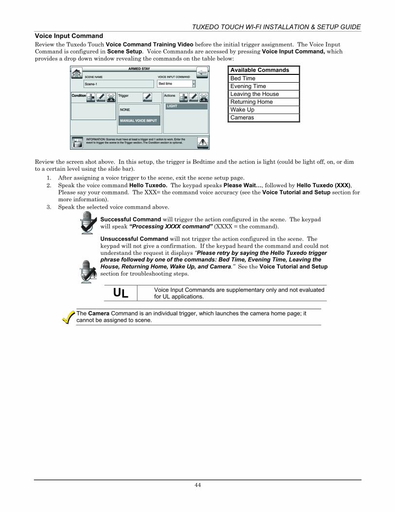
TUXEDO TOUCH WI-FI INSTALLATION & SETUP GUIDE
44
Voice Input Command Review the Tuxedo Touch Voice Command Training Video before the initial trigger assignment. The Voice Input Command is configured in Scene Setup. Voice Commands are accessed by pressing Voice Input Command, which provides a drop down window revealing the commands on the table below:
Available Commands Bed Time Evening Time Leaving the House Returning Home Wake Up Cameras
Review the screen shot above. In this setup, the trigger is Bedtime and the action is light (could be light off, on, or dim to a certain level using the slide bar).
1. After assigning a voice trigger to the scene, exit the scene setup page. 2. Speak the voice command Hello Tuxedo. The keypad speaks Please Wait…, followed by Hello Tuxedo (XXX),
Please say your command. The XXX= the command voice accuracy (see the Voice Tutorial and Setup section for more information).
3. Speak the selected voice command above.
Successful Command will trigger the action configured in the scene. The keypad will speak “Processing XXXX command” (XXXX = the command).
Unsuccessful Command will not trigger the action configured in the scene. The keypad will not give a confirmation. If the keypad heard the command and could not understand the request it displays “Please retry by saying the Hello Tuxedo trigger phrase followed by one of the commands: Bed Time, Evening Time, Leaving the House, Returning Home, Wake Up, and Camera.” See the Voice Tutorial and Setup section for troubleshooting steps.
UL Voice Input Commands are supplementary only and not evaluated for UL applications.
The Camera Command is an individual trigger, which launches the camera home page; it cannot be assigned to scene.

TUXEDO TOUCH WI-FI INSTALLATION & SETUP GUIDE
45
Detailed Scene Configuration Scenes must have at least one trigger, 1 action (up to 5) and the event to trigger. The Condition section is optional.
Time
Set the TIME: Press Trigger/Condition > Add > TIME > Set the occurrence. If ONCE, Enter Date; if REPEATED > choose days of the week; if BY CLOCK > press on the Hour/Minutes displayed and enter the Start and End Time > press on AM/PM; if SUNRISE or SUNSET > BY CLOCK until the desired setting is displayed. Check the Critical Event check box to record and store a maximum of two events even when the SD card is not available. If more than two critical events occur, then the older one is replaced by the latest event. NOTES:
• The Sunrise/Sunset feature is dependent on the “Region” selected in the “Weather Forecast” section and requires internet access for accuracy.
• BY CLOCK allows you to activate the scene for a specified period.
Security Set the Security Mode: Press Trigger/Condition/Action > Add > SECURITY > DISARM, AWAY, STAY, NIGHT, AWAY SECURED or ALARM > User Code, if required. NOTES: • AWAY triggers upon arming away. • AWAY SECURED triggers when exit delay has expired.
Thermostat Set the Thermostat: Press Trigger/Condition/Action > Add. Press THERMOSTAT and select a Thermostat device from the drop-down menu or press Select Thermostat Group to activate more than one device. See the Group Setup section. Use ABOVE or BELOW to increase/decrease the temperature or press the Temperature Value box and enter two digits for the desired temperature. NOTES: • Test thermostats first to ensure proper function in the scene.
• Some thermostats do not update temperature status automatically (i.e., Wayne Dalton). Light Set Lights (on/off): Press Action box > Add > LIGHT > Select Light Device from the drop-down
menu or press Select Lights Group (to activate more than one device) > set the action to ON, OFF, Dim level for multi-level switches; or select ON FOR TIME and press Hour/Minutes > amount time. NOTE: ON FOR TIME allows you to activate the scene for a specified period.
Door Set the Door Locks: In the Trigger box, press Add > DOOR > Door Device from the drop-down menu. Press LOCKED, UNLOCKED or CODE UNLOCKED for the Action. In the Condition box, press LOCKED or UNLOCKED. Next, an action must be programmed. NOTES: • Motorized door lock bolts physically lock and unlock when activated, but if the door lock installed
is a non-motorized type, activation allows the door to be manually unlocked without a key. See Compatible Devices section later in this document.
• When using some older Kwikset® Smartcode electronic deadbolt door locks (in a Scene that is programmed to trigger when unlocked) the Scene does not trigger if using a key; enter a user code.
Garage Door
Set the Garage Door: Press Trigger/Condition/Action > Add .> GARAGE DOOR > Garage Door Device, select from the drop-down menu or press Garage Door Group to activate more than one device. Select OPENED or CLOSED. The Action Menu option is OPEN or CLOSE. In CONDITIONS OPENED or CLOSED. NOTE: Review the disclaimer in the section Add Garage Door Module.
Water Valve
Set the Water Valve: Press Trigger/Condition/Action > ADD > WATER VALVE > WATER VALVE DEVICES from the drop-down menu or select Water Valve Group to activate more than one device. The options for Trigger/Condition are OPENED or CLOSED and for Action is OPEN or CLOSE.
Zones Set the Zones: In the TRIGGER/Condition box, press Add. Press ZONES and select a zone from the drop-down menu. Select Restore, Alarm or Fault.
NOTE: Do not use 24-hour silent zone restore/fault in the pre-condition and trigger fields on commercial panels.

TUXEDO TOUCH WI-FI INSTALLATION & SETUP GUIDE
46
Group Setup A group is a defined collection of the same type of Z-Wave devices (such as only light modules, or only door locks, etc.) that can be used in scenes. When used in a scene and the scene activates, all devices assigned to that group activate. Up to 20 groups can be created with up to five of the same type devices in each group, such as five door locks, etc. Follow the procedure below to create a Group.
1. Press Group Setup > Add . 2. Highlight Group Name > Group Name. 3. Select the Group Type (Binary Light, Door Lock, Thermostat, Multilevel Switch, Shades, Water Valve, Garage
Door Controllers, and Other) from the drop-down list. 4. Highlight the device(s) from the drop-down list that you want to add to this Group and press Save. A
confirmation message is displayed: Z-Wave device group settings saved. NOTES:
• Select Edit to make changes to existing Groups; use Delete to delete a Group. • The “Water Valve Group” is excluded from the “All Switches On/Off” command on the “Device Control” page.
Room Setup A room is a defined collection of different types of Z-Wave devices (such as light modules, door locks, thermostats, etc.) which can be used to organize the Z-Wave devices. Up to 50 rooms can be created with no limitation to the number of devices in each room.
Example 1: Screen Interface
Example 2: Assigning Devices
Room Name
Kitchen Bedroom Living Room
Device 1 Kitchen Over Head Light
Bed. Lamp
L.R. Lamp
Device 2 Kitchen Cabinet Lights
Bed. Fan L.R. Fan
Device 3 Kitchen Fan Bed Overhead Light
L.R. Outlet
Device 4 Kitchen
Follow the procedure below to create a Room. 1. Press Room Setup > Add. 2. Enter a room name > GO. 3. Check the box next to the device(s) that will be assigned to this Room > Save. 4. Select Edit to make changes to existing Rooms; use Delete to delete a Room. 5. If settings were changed, a pop-up confirmation window displays Settings Saved.
Secondary Tuxedo Controller After all Z-Wave devices have been added into the Primary Tuxedo (#1), the device information can be downloaded to a Secondary Tuxedo (#2). Up to 231 secondary plus 1 primary controller, for a total of 232. Keep Tuxedos within 40 feet of each other (if it does not work, move the keypad closer to the primary), apply power to Tuxedo #2 and do the following:
1. At Tuxedo #1 (Primary Controller): Press Automation > Z-Wave Setup ; the “Z-Wave Device Management” screen is displayed. NOTE: If used for Remote Services, Tuxedo should not be configured as a secondary controller. See the Remote Services section later in this document.
2. At Tuxedo #2 (Secondary Controller): Press the Z-Wave Primary icon (located in the lower right side of the
screen). The icon changes to an icon, representing the controller is now in secondary mode.
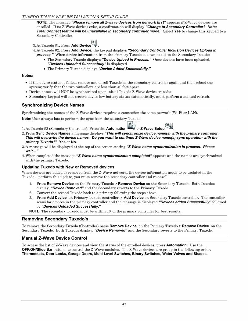
TUXEDO TOUCH WI-FI INSTALLATION & SETUP GUIDE
47
NOTE: The message “Please remove all Z-wave devices from network first” appears if Z-Wave devices are enrolled. If no Z-Wave devices exist, a confirmation will display “Change to Secondary Controller? Note: Total Connect feature will be unavailable in secondary controller mode.” Select Yes to change this keypad to a Secondary Controller.
3. At Tuxedo #1, Press Add Device . 4. At Tuxedo #2: Press Add Device, the keypad displays “Secondary Controller Inclusion Devices Upload in
process.” When device information from the Primary Tuxedo is downloaded to the Secondary Tuxedo: • The Secondary Tuxedo displays “Device Upload in Process.” Once devices have been uploaded,
“Devices Uploaded Successfully” is displayed. • The Primary Tuxedo displays “Device Added Successfully.”
Notes:
• If the device status is failed, remove and enroll Tuxedo as the secondary controller again and then reboot the system; verify that the two controllers are less than 40 feet apart.
• Device names will NOT be synchronized upon initial Tuxedo Z-Wave device transfer. • Secondary keypad will not receive device low battery status automatically, must perform a manual refresh.
Synchronizing Device Names Synchronizing the names of the Z-Wave devices requires a connection the same network (Wi-Fi or LAN). Note: User always has to perform the sync from the secondary Tuxedo.
1. At Tuxedo #2 (Secondary Controller): Press the Automation > Z-Wave Setup . 2. Press Sync Device Names a message displays “This will synchronize device name(s) with the primary controller.
This will overwrite the device names. Do you want to continue Z-Wave device name(s) sync operation with the primary Tuxedo?” Yes or No.
3. A message will be displayed at the top of the screen stating “Z-Wave name synchronization in process. Please wait…”
4. When completed the message “Z-Wave name synchronization completed” appears and the names are synchronized with the primary Tuxedo.
Updating Tuxedo with New or Removed devices When devices are added or removed from the Z-Wave network, the device information needs to be updated in the Tuxedo. perform this update, you must remove the secondary controller and re-enroll.
1. Press Remove Device on the Primary Tuxedo > Remove Device on the Secondary Tuxedo. Both Tuxedos display, “Device Removed” and the Secondary reverts to the Primary Tuxedo.
2. Convert the second Tuxedo back to a primary following the steps above. 3. Press Add Device on Primary Tuxedo controller > Add Device on Secondary Tuxedo controller. The controller
scans for devices in the primary controller and the message is displayed “Devices added Successfully” followed by “Devices Uploaded Successfully.”
NOTE: The secondary Tuxedo must be within 10’ of the primary controller for best results.
Removing Secondary Tuxedo’s To remove the Secondary Tuxedo (Controller) press Remove Device on the Primary Tuxedo > Remove Device on the Secondary Tuxedo. Both Tuxedos display, “Device Removed” and the Secondary reverts to the Primary Tuxedo.
Manual Z-Wave Device Control To access the list of Z-Wave devices and view the status of the enrolled devices, press Automation. Use the OFF/ON/Slide Bar buttons to control the Z-Wave modules. The Z-Wave devices are group in the following order: Thermostats, Door Locks, Garage Doors, Multi-Level Switches, Binary Switches, Water Valves and Shades.

TUXEDO TOUCH WI-FI INSTALLATION & SETUP GUIDE
48
Integrating Total Connect Remote Services The Tuxedo supports Remote Services for controlling Z-Wave devices and scenes remotely from an associated Total Connect account.
LAN or Wi-Fi MUST be enabled for proper integration with Total Connect. Synchronizing is required before the enabled devices will display in Total Connect.
Enabling Devices for Total Connect After devices have been added to the Tuxedo, the next step is to add them to Total Connect.
1. From the home screen press Setup > System, > CS Setup. Enter the Authorized code and press TC SERVER INFO.
2. Press TC Enable , the Z-Wave Device Management for Total Connect screen is displayed. 3. Select the device(s) that you want to enable/disable in Total Connect.
NOTE: Some devices may need to be enabled after a software upgrade. 4. Press Save when done. 5. After devices have been enabled for Total Connect, follow the Total Connect prompts to synchronize the data
with Tuxedo. NOTES:
1. On Total Connect, the maximum number of supported devices is 40 switches (including Water Valves), 3 thermostats, 4 door locks and 3 Garage Door Controllers.
2. Tuxedo supports 232 devices (including the Tuxedo keypads) in the Z-Wave network. Controlling Automation (Z-Wave) Devices Remotely Use Total Connect to control Z-Wave devices: lamp modules (binary switch), dimmer modules (multilevel switch), thermostats, door locks, garage door controllers, water valves, shades, etc., from a smart phone, iPad®, AndroidTM Tablet, or PC. If accessing on a smart device (Apple or Android) verify the correct App has been download and installed.
1. Access the Total Connect account and navigate to the Automation section of the dashboard. 2. Select a displayed device and click the desired action. Refer to the Total Connect Online Help Guide for further
details on controlling Z-Wave devices.

TUXEDO TOUCH WI-FI INSTALLATION & SETUP GUIDE
49
Viewing and Controlling Total Connect Scenes from Tuxedo Use Scenes to display and control scenes that have been created in Total Connect.
1. From the “Home” screen, press Automation > Scene Setup > Remote. The screen displays a list of scenes created in Total Connect.
2. To control a Remote scene, select the desired scene, and then click the appropriate action (ex. Run).
Creating Scenes in Total Connect The following table summarizes the relationships between Total Connect scenes and Tuxedo scenes:
Controlling Device
Scenes created in Total Connect Scenes created in Tuxedo View Edit Scenes View Edit Scenes
Total Connect Yes Yes No No Tuxedo Yes No Yes Yes
Note: For troubleshooting purposes, Total Connect server information (including IP addresses) can be viewed on the Total Connect Server Setup screen by pressing the TC SERVER INFO button.
Use the Automation section of the dashboard in Total Connect to create up to 20 scenes. Refer to the Total Connect Online Help Guide for further details and device limitations for creating an automation scene.
1. Access the Total Connect account and navigate to the Automation module. Press Create New > Enter a name for the scene > select an icon > and then press on the check boxes for the various device actions desired for that scene. Set the thermostat, if used, to the desired mode and/or temperature for that scene. Press Save when done.
Scene triggers and actions created in Total Connect can be edited only from Total Connect. Scene conditions cannot be programmed through Total Connect.
2. After scenes have been created, follow the Total Connect prompts to synchronize the data with the Tuxedo.
Synchronizing is required before scenes created in Total Connect will display in Tuxedo.
Total Connect Server Screen for Troubleshooting
The “TC Server Info” screen displays the current server information and Z-Wave device status. This information is typically used for IP connection troubleshooting purposes in collaboration with a service technician.
Diagnostic Connect
Clicking Diagnostic Connect in the bottom left corner will test the communication status to the AlarmNet server. If the test fails, check your network connection.
Cancel This cancels the Diagnostic Test above.
Total Connect Device Select
Verification of the Z-Wave status: If enabled it will communicate Z-Wave status to Total Connect 2.0. Pressing the “TC” icon will populate a list of all your Z-Wave devices with an enable or disable option. This will allow or prevent those chosen devices from appearing on the Total Connect account.
To access Total Connect Server Information and Z-Wave Status from the Tuxedo keypad, do the following:
1. From the “Home” Screen, press Setup > System > CS Setup > enter the installer code (if required). 2. Press the TC SERVER INFO button. The “Total Connect Server Setup” screen is displayed with the current
Server information and Z-Wave Status (enabled/disabled). NOTE: These fields are for reference only and cannot be edited.
3. Press Connect to test the connection to the AlarmNet servers.
TUXEDO TOUCH WI-FI INSTALLATION & SETUP GUIDE
50
Appendix A: Important Notes For additional troubleshooting procedures, refer to the Control Panel Installation Guide.
General Notes • You may check to see whether the Chime Mode is ON or OFF by viewing the keypad Operating Modes screen as
described in the “Operating Modes” section. • Note that some displays on the keypad may not have enough space to display the full name of a partition. When
this occurs, the display shows as many characters as possible starting at the beginning of the partition name. We recommend that the partition name be kept to a maximum of seven characters to ensure the “H” which indicates the home partition may be seen.
• “Exit Error” and “Auto Arm Alert, Please Leave Now” messages are not displayed by the keypad. • When the system has 6150Vs or 6160Vs, and 6271Vs attached, the Additional Console setting in the 6150Vs
(displayed as A on the 6150V) must be set to one and the Additional Console setting in the 6160Vs must be set to Yes.
Commercial System Notes • If the Aux Relay function is set for alarm silenced by User Code + # + 67, this command may only be entered in the
console emulation mode. • Do not use the common lobby logic function. • If fields 2*22 (Display Fire Alarms of other Partitions), 2*23 (Display Burg & Panic of other Partitions), or 2*24
(Display Troubles of other Partitions) are enabled, the zones that created the conditions cannot be viewed. You must go to that zone's home partition to view.
• If field 1*11 (Zone Bypass After Disarm) is enabled, you must use the keypad’s Console Emulation Mode and the commands “Code” + “64” (unbypass all) or “Code” + “6” + “Zone Number” (unbypass zone) to remove zone bypasses.
• The First to Alarm Display Lock feature (field 1*10) is not supported by the keypad. • RF Low Battery messages are not supported by the keypad except in the Show Zones screen where a Battery Icon is
displayed for the zone with the low battery.
Residential System Notes • If the Clean Me option is set, when the maintenance signal is received a “Fire Maintenance” message and the
Display Faults is shown. However, if you display the faults, zone 1 is not shown as a faulted zone. • If RF Jam Reports are selected and RF Jam is detected, the User Authorization screen displays “Trouble ZN100 RF
Receiver.” If you enter the console emulation mode, the display shows “Check 90 RF Receiver Jam.” • Do not use the Custom Word reminder feature.
User Related Notes • Users added to the system using the keypad graphic user screen must be deleted from the keypad using the graphic
screen as well. Deleting users from the panel by any other means (alpha keypad, console emulation mode, or Compass downloader) does not automatically delete them from the keypad.
• If the panel has exit tones enabled and you arm the system in the Away mode, the keypad beeps continuously throughout the exit period.
Use the console emulation mode for the following functions: • Programming more than 10 system users. • Programming the Pager report option for users of residential control panels (e.g., VISTA-15P/20P). • Special Function Key operations (such as macros or single-button paging). • End-User Scheduling. • To check for an “Alarm Cancelled” message (on commercial panels only) if this feature has been enabled in the
system.

TUXEDO TOUCH WI-FI INSTALLATION & SETUP GUIDE
51
Appendix B: Z-Wave Notes Z-Wave Compatible Devices Z-Wave devices may vary; follow the instructions in the User’s Guide for your specific device when adding and deleting devices into the Z-Wave network.
Visit https://mywebtech.honeywell.com/ or http://www.tuxedotouchtoolkit.com/ for a complete list of compatible Z-Wave devices. Refer to the document titled “Z-Wave Compatibility Chart.”
NOTE: The listed companies in the document referenced online may manufacturer multiple Z-Wave devices. Installing ‘like’ modules not included on this list may produce unpredictable results. These devices have not been confirmed as compatible.
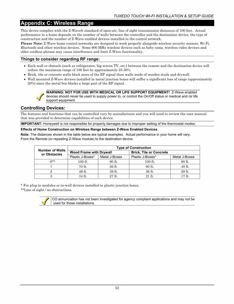
TUXEDO TOUCH WI-FI INSTALLATION & SETUP GUIDE
52
Appendix C: Wireless Range This device complies with the Z-Wave® standard of open-air, line of sight transmission distances of 100 feet. Actual performance in a home depends on the number of walls between the controller and the destination device, the type of construction and the number of Z-Wave enabled devices installed in the control network. Please Note: Z-Wave home control networks are designed to work properly alongside wireless security sensors, Wi-Fi, Bluetooth and other wireless devices. Some 900 MHz wireless devices such as baby cams, wireless video devices and older cordless phones may cause interference and limit Z-Wave functionality.
Things to consider regarding RF range: • Each wall or obstacle (such as refrigerator, big screen TV, etc.) between the remote and the destination device will
reduce the maximum range of 100 feet by approximately 25-30%. • Brick, tile or concrete walls block more of the RF signal than walls made of wooden studs and drywall. • Wall mounted Z-Wave devices installed in metal junction boxes will suffer a significant loss of range (approximately
20%) since the metal box blocks a large part of the RF signal.
WARNING: NOT FOR USE WITH MEDICAL OR LIFE SUPPORT EQUIPMENT! Z-Wave enabled devices should never be used to supply power to, or control the On/Off status or medical and /or life support equipment.
Controlling Devices: The features and functions that can be controlled vary by manufacturer and you will need to review the user manual that was provided to determine capabilities of each device. IMPORTANT: Honeywell is not responsible for property damages due to improper setting of the thermostat modes. Effects of Home Construction on Wireless Range between Z-Wave Enabled Devices Note: The distances shown in the table below are typical examples. Actual performance in your home will vary. From the Remote (or repeating Z-Wave module) to the destination device:
Number of Walls or Obstacles
Type of Construction Wood Frame with Drywall Brick, Tile or Concrete Plastic J-Boxes* Metal J-Boxes Plastic J-Boxes* Metal J-Boxes
0** 100 ft. 80 ft. 100 ft. 80 ft. 1 70 ft. 56 ft. 60 ft. 48 ft. 2 49 ft. 39 ft. 36 ft. 29 ft. 3 34 ft. 27 ft. 21 ft. 17 ft.
* For plug-in modules or in-wall devices installed in plastic junction boxes. **Line of sight / no obstructions.
CO annunciation has not been investigated for agency compliant applications and may not be
used for those installations.

TUXEDO TOUCH WI-FI INSTALLATION & SETUP GUIDE
53
Navigation Icons To aid in the navigation through the Tuxedo touch-screens, a set of user-friendly icons has been provided. The appearance and function are described below.
ICON ICON TITLE FUNCTION
“Product/Training Videos” Accesses the “Product Introduction and Training Videos.”
"Message" Record and retrieve Voice Messages.
"Automation" Accesses the Z-Wave setup, Scene setup, and Group/Room setup screens.
"Security" Accesses the "Security" screen.
“Home” Returns you to the "Home" screen.
“Back” Reverts to the last screen viewed.
“Panic”
Displays Emergency functions (as programmed by the installer). See programming the Control Panel note. Note: This icon is displayed and active on all screens except while in the Clean Screen mode, during an LCD Display test in Diagnostics, and from the Video and Camera screen.
“Control Panel Message” This icon alerts the user to a Control Panel Message.
“Setup” Accesses the Setup menus.
“Multi-Media” Accesses the Message, Camera, Picture and Video features.
“Video” Allows user to play video files.
“Picture” Allows user to display personal photos in a slide show format.
“Voice Status” Allows user to hear system status.
“Camera” Press to access camera settings.
“Event View” Press to access video recordings.

TUXEDO TOUCH WI-FI INSTALLATION & SETUP GUIDE
54
Specifications Mechanical Specifications: Width: 8.23 inches (209.04mm)
Operating Environment: Humidity : 93% RH, non- condensing
Height: 5.59 inches (141.99mm) Depth:1.13 inches (28.70mm)
Temperature: Operating : 14˚F to 131˚F / -10˚C to 55˚C (UL tested 32˚-
120˚F / 0 to 49˚C) Shipping / Storage: -40˚F to 158˚F / -40˚C to 70˚C
Electrical Specifications: 9.6VDC 12VDC 13.8VDC Backlight OFF, Sound OFF, WIFI ON 170mA 140mA 130mA Backlight ON, Sound OFF, WIFI ON 280mA 225mA 200mA Backlight ON, Sound ON, WIFI ON 340mA 260mA 250mA

TUXEDO TOUCH WI-FI INSTALLATION & SETUP GUIDE
55
NOTES

TUXEDO TOUCH WI-FI INSTALLATION & SETUP GUIDE
56
NOTES


57
FEDERAL COMMUNICATIONS COMMISSION (FCC) & INDUSTRY CANADA (IC) STATEMENTS The user shall not make any changes or modifications to the equipment unless authorized by the Installation Instructions or User's Manual. Unauthorized changes or modifications could void the user's authority to operate the equipment.
CLASS B DIGITAL DEVICE STATEMENT This equipment has been tested to FCC requirements and has been found acceptable for use. The FCC requires the following statement for your information: This equipment generates and uses radio frequency energy and if not installed and used properly, that is, in strict accordance with the manufacturer's instructions, may cause interference to radio and television reception. It has been type tested and found to comply with the limits for a Class B computing device in accordance with the specifications in Part 15 of FCC Rules, which are designed to provide reasonable protection against such interference in a residential installation. However, there is no guarantee that interference will not occur in a particular installation. If this equipment does cause interference to radio or television reception, which can be determined by turning the equipment off and on, the user is encouraged to try to correct the interference by one or more of the following measures: • If using an indoor antenna, have a quality outdoor antenna installed. • Reorient the receiving antenna until interference is reduced or eliminated. • Move the radio or television receiver away from the receiver/control. • Move the antenna leads away from any wire runs to the receiver/control. • Plug the receiver/control into a different outlet so that it and the radio or television receiver are on different
branch circuits. • Consult the dealer or an experienced radio/TV technician for help.
INDUSTRY CANADA CLASS B STATEMENT This Class B digital apparatus complies with Canadian ICES-003. Cet appareil numérique de la classe B est conforme à la norme NMB-003 du Canada.
FCC / IC STATEMENT This device complies with Part 15 of the FCC Rules, and RSS-210 of Industry Canada. Operation is subject to the following two conditions: (1) This device may not cause harmful interference, and (2) This device must accept any interference received, including interference that may cause undesired operation.
Cet appareil est conforme à la partie 15 des règles de la FCC & de RSS-210 des Industries Canada. Son fonctionnement est soumis aux conditions suivantes: (1) Cet appareil ne doit pas causer d’interférences nuisibles. (2) Cet appareil doit accepter toute interférence reçue y compris les interférences causant une réception indésirable.
USE OF THESE PRODUCTS IN COMBINATION WITH NON-HONEYWELL PRODUCTS IN A WIRELESS MESH NETWORK, OR TO ACCESS, MONITOR OR CONTROL DEVICES IN A WIRELESS MESH NETWORK VIA THE INTERNET OR ANOTHER EXTERNAL WIDE AREA NETWORK, MAY REQUIRE A SEPARATE LICENSE FROM SIPCO, LLC. FOR MORE INFORMATION, CONTACT SIPCO, LLC OR IPCO, LLC AT 8215 ROSWELL RD., BUILDING 900, SUITE 950, ATLANTA, GA 303350, OR AT WWW.SIPCOLLC.COM OR WWW.INTUSIQ.COM.
RF EXPOSURE WARNING The Tuxedo must be installed to provide a separation distance of at least 7.8 in. (20 cm) from all persons and must not be co-located or operating in conjunction with any other antenna or transmitter except in accordance with FCC multi-transmitter product procedures.

SUPPORT & WARRANTY For the latest documentation and online support information, please go to:
https://mywebtech.honeywell.com/
For the latest warranty information, please go to: www.honeywell.com/security/hsc/resources/wa.
For patent information, see www.honeywell.com/patents
MyWebTech
Warranty
Patents
Ê800-16571V2SŠ 800-16571V2 8/15 Rev. B
2 Corporate Center Drive, Suite 100 P.O. Box 9040, Melville, NY 11747
Copyright © 2014 Honeywell International www.honeywell.com/security