moden: obstacle-driven elastic network for line-of-sight ...mmv/papers/09epia-moden.pdf · moden:...
TRANSCRIPT
MODEN: Obstacle-driven Elastic Network forLine-of-Sight Communication?
Francisco S. Melo and Manuela Veloso
Computer Science DepartmentCarnegie Mellon UniversityPittsburgh, PA 15213, USA{fmelo,veloso}@cs.cmu.edu
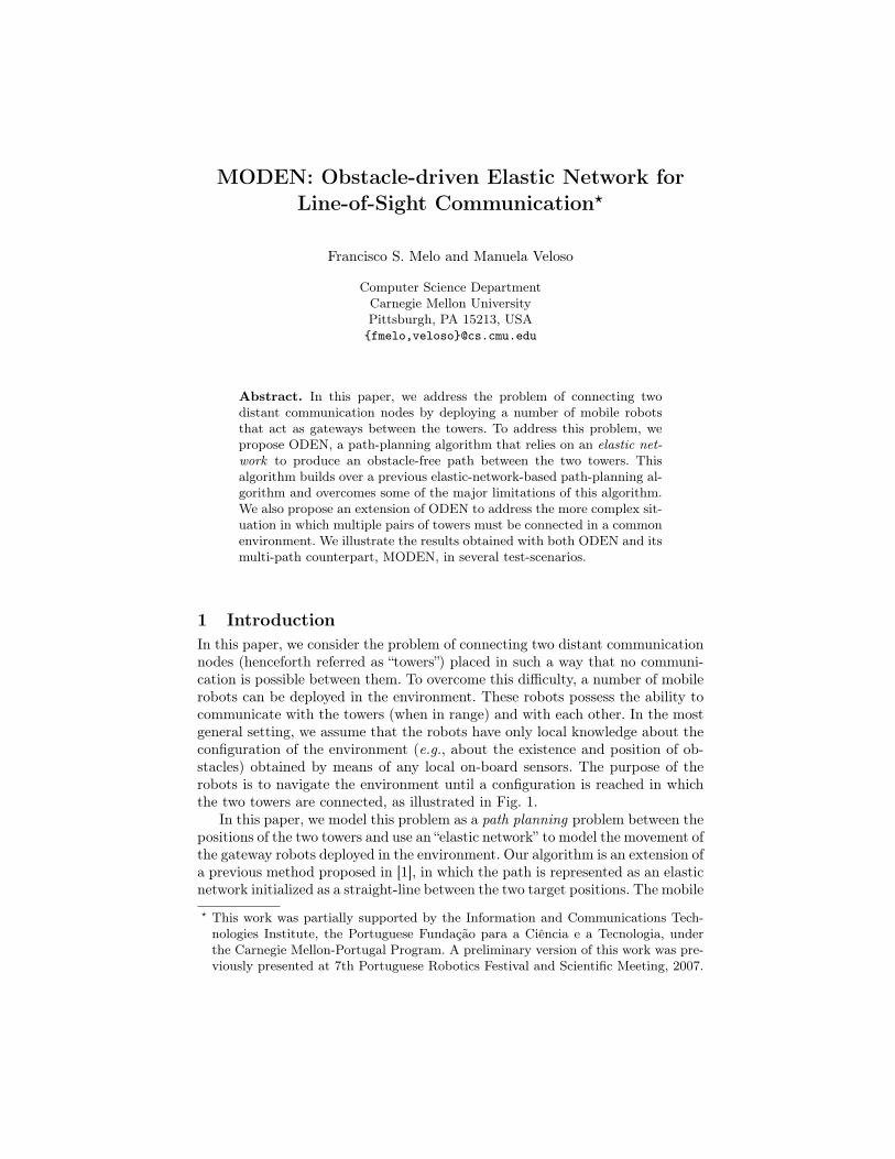
Abstract. In this paper, we address the problem of connecting twodistant communication nodes by deploying a number of mobile robotsthat act as gateways between the towers. To address this problem, wepropose ODEN, a path-planning algorithm that relies on an elastic net-work to produce an obstacle-free path between the two towers. Thisalgorithm builds over a previous elastic-network-based path-planning al-gorithm and overcomes some of the major limitations of this algorithm.We also propose an extension of ODEN to address the more complex sit-uation in which multiple pairs of towers must be connected in a commonenvironment. We illustrate the results obtained with both ODEN and itsmulti-path counterpart, MODEN, in several test-scenarios.
1 IntroductionIn this paper, we consider the problem of connecting two distant communicationnodes (henceforth referred as “towers”) placed in such a way that no communi-cation is possible between them. To overcome this difficulty, a number of mobilerobots can be deployed in the environment. These robots possess the ability tocommunicate with the towers (when in range) and with each other. In the mostgeneral setting, we assume that the robots have only local knowledge about theconfiguration of the environment (e.g., about the existence and position of ob-stacles) obtained by means of any local on-board sensors. The purpose of therobots is to navigate the environment until a configuration is reached in whichthe two towers are connected, as illustrated in Fig. 1.
In this paper, we model this problem as a path planning problem between thepositions of the two towers and use an “elastic network” to model the movement ofthe gateway robots deployed in the environment. Our algorithm is an extension ofa previous method proposed in [1], in which the path is represented as an elasticnetwork initialized as a straight-line between the two target positions. The mobile? This work was partially supported by the Information and Communications Tech-nologies Institute, the Portuguese Fundação para a Ciência e a Tecnologia, underthe Carnegie Mellon-Portugal Program. A preliminary version of this work was pre-viously presented at 7th Portuguese Robotics Festival and Scientific Meeting, 2007.

Obstacle
Node A
Node B
Robot 1
Robot 2
Robot 3
Fig. 1. Illustration of the typical scenario considered in the paper.
nodes in the network (the mobile robots in our scenario) are “attracted” towardfree-space and “repelled” away from the obstacles, yielding an obstacle-free path.
The contributions of this paper are two-fold. On one hand, we improve on theoriginal algorithm from [1] by proposing a new update rule that yields smootherand more efficient deployment of the robots, in a sense soon to be made clear.This leads to the ODEN algorithm, our first contribution. On the other hand, wepropose an extension of ODEN to address the more complex situation in whichmultiple pairs of towers must be connected in a common environment. In thissituation, and to minimize interference, it is desirable that the deployment ofthe robots is conducted in such a way as to minimize intersection between thedifferent communication paths. This leads to MODEN, the “multi-path” versionof ODEN and the second contribution of this paper.
To motivate this work, consider, for example, a forest fire situation in whichfiremen must maintain contact with a base-station. In order to do so, they cancarry small, portable mobile units that they drop as they move toward their as-signed position. These units will ensure connectivity between each fireman andthe base-station by locally adjusting their position so as to improve connectiv-ity and minimize interference. Aimed at such applications, the approach in thispaper explicitly considers the existence of obstacles in the environment, drivingthis work away from other works addressing open space deployment and con-nectivity [2]. Furthermore, we are particularly interested in modeling scenariosin which the robots move in an unstructured (outdoor) environment. In thesescenarios, signal obstruction can arise from obstacles such as groups of trees thatcan actually be traversed by the robot, but cause severe decrease in the abilityof the robot to communicate with its neighbors. Also, in the setting consideredherein, we are not concerned with radio-based navigation or localization, a topicof recent current research [3–7]. As will be apparent from our algorithm, therobots need only minimal navigation capabilities. In particular, the algorithmwill not require them to use any localization or path planning algorithm, butsimply execute very simple movement primitives (such as moving straight in agiven direction). Finally, the problem considered herein is, in a sense, closelyrelated to the problem addressed in [8]. The latter work proposes an algorith-mic procedure to determines when the robots can move in order not to loosethe overall connectivity of the network. In this paper we propose an algorithmicprocedure to determine how the robots can move in order to improve the overallconnectivity of the network.
Obstacle
Sample point
wi
wi+1
wi−1
(a)
Sample point
wi+1
wi−1wi
Obstacle
(b)
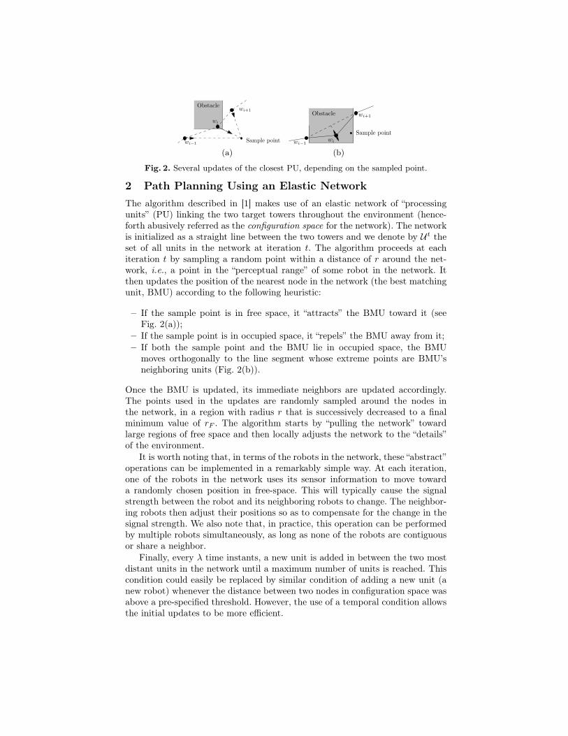
Fig. 2. Several updates of the closest PU, depending on the sampled point.
2 Path Planning Using an Elastic NetworkThe algorithm described in [1] makes use of an elastic network of “processingunits” (PU) linking the two target towers throughout the environment (hence-forth abusively referred as the configuration space for the network). The networkis initialized as a straight line between the two towers and we denote by U t theset of all units in the network at iteration t. The algorithm proceeds at eachiteration t by sampling a random point within a distance of r around the net-work, i.e., a point in the “perceptual range” of some robot in the network. Itthen updates the position of the nearest node in the network (the best matchingunit, BMU) according to the following heuristic:
– If the sample point is in free space, it “attracts” the BMU toward it (seeFig. 2(a));
– If the sample point is in occupied space, it “repels” the BMU away from it;– If both the sample point and the BMU lie in occupied space, the BMU
moves orthogonally to the line segment whose extreme points are BMU’sneighboring units (Fig. 2(b)).
Once the BMU is updated, its immediate neighbors are updated accordingly.The points used in the updates are randomly sampled around the nodes inthe network, in a region with radius r that is successively decreased to a finalminimum value of rF . The algorithm starts by “pulling the network” towardlarge regions of free space and then locally adjusts the network to the “details”of the environment.
It is worth noting that, in terms of the robots in the network, these “abstract”operations can be implemented in a remarkably simple way. At each iteration,one of the robots in the network uses its sensor information to move towarda randomly chosen position in free-space. This will typically cause the signalstrength between the robot and its neighboring robots to change. The neighbor-ing robots then adjust their positions so as to compensate for the change in thesignal strength. We also note that, in practice, this operation can be performedby multiple robots simultaneously, as long as none of the robots are contiguousor share a neighbor.
Finally, every λ time instants, a new unit is added in between the two mostdistant units in the network until a maximum number of units is reached. Thiscondition could easily be replaced by similar condition of adding a new unit (anew robot) whenever the distance between two nodes in configuration space wasabove a pre-specified threshold. However, the use of a temporal condition allowsthe initial updates to be more efficient.

(a) No obstacles. (b) 25 obstacles.
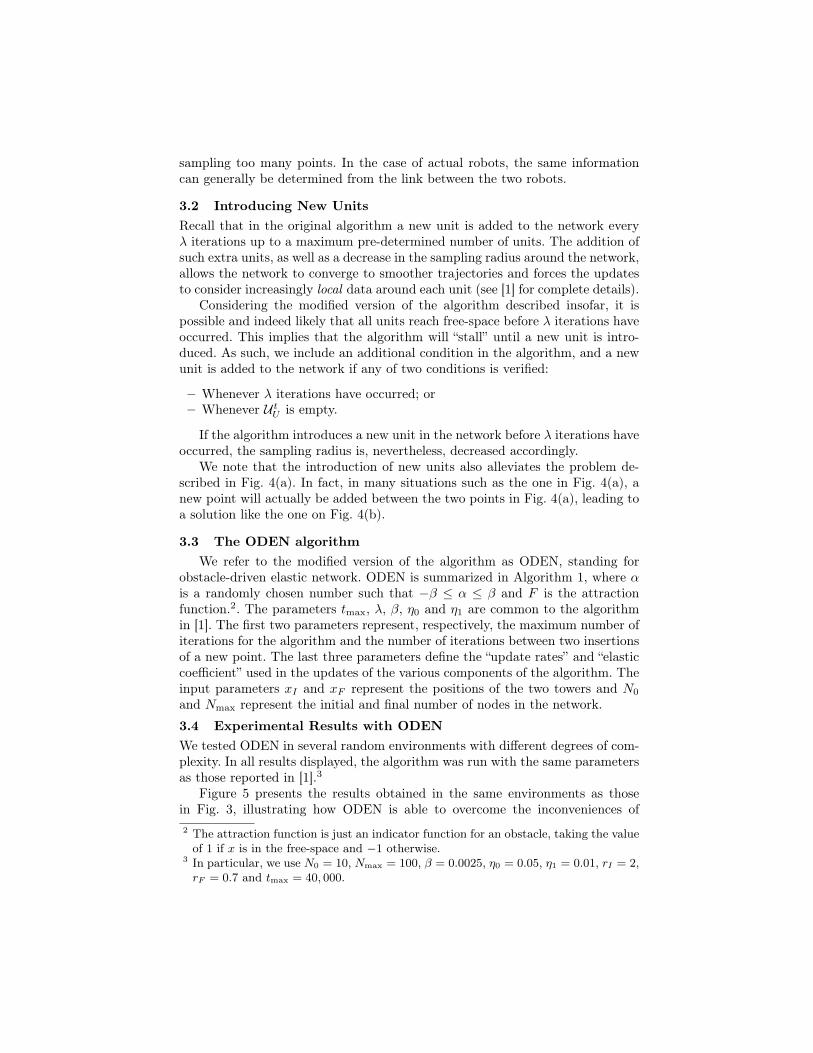
Fig. 3. Trajectories obtained by the original algorithm.
The term elastic network arises from the fact that each unit exerts someconservative tension on its neighboring units so as to maintain their relativepositions. In other words, the updated PU is “pulled” by its neighbors and also“pulls” its neighboring units. More details on the algorithm can be found in thereferred work [1]. This “elastic tension” between neighboring units can be seen asa local adjustment that each of the units performs whenever one of its neighborsmoves in order to improve connectivity.
The method has several interesting properties. It is extremely simple to im-plement. It only requires a sampling mechanism around the network and theevaluation of the attraction function. This attraction function merely determineswhether a point is in free-space or in occupied space and the update of a unitreduces to a few extremely simple operations that translate into very simple mo-tion commands. Also, given its simplicity, it is a surprisingly efficient algorithm,being in fact able to find obstacle-free paths between the desired points with verylittle computational effort. The examples reported in [1] were able to determineobstacle-free paths in several complex environments in few thousand iterations.Furthermore, it does not require any search or any model of the environment,but just a sampling function able to determine whether a point lies in free-spaceor not. Finally, the method is local in that each unit is updated considering onlyits immediate neighborhood. This is a very interesting feature of the algorithmfor the particular set of problems we are interested in. In our setting, each unit isactually an independent robot that must adjust its individual position communi-cating only with its neighboring units and sampling the surrounding space, butthe method still provides a way of determining a global obstacle-free network.
However, it also presents several inconveniences. First of all, the algorithmwill often spend a lot of iterations updating units that need not be updated. Thishappens, for example, in an obstacle-free environment or any environment wherethere is a lot of free space, where most of the units will already start away fromany obstacle. Furthermore, because sample points in free-space keep attractingthe network to free-space, this may lead to peculiar trajectories as depicted inFig. 3. Finally, the algorithm was designed to run for a fixed (usually large)number of iterations and takes generally this number of iterations to terminatebefore a path is produced. In the next section we propose a modification of thealgorithm that, while maintaining the simplicity of the original algorithm andits functional principle, alleviates the reported inconveniences.
Obstacle
(a)
Obstacle
New point
(b)
Obstacle
Edgeintersects
object
Unit insideobject
Obstacle
(c)
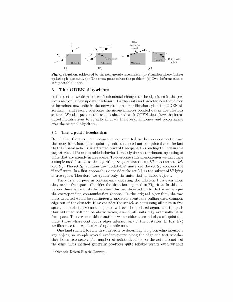
Fig. 4. Situations addressed by the new update mechanism. (a) Situation where furtherupdating is desirable. (b) The extra point solves the problem. (c) Two different classesof “updatable” units.
3 The ODEN AlgorithmIn this section we describe two fundamental changes to the algorithm in the pre-vious section: a new update mechanism for the units and an additional conditionto introduce new units in the network. These modifications yield the ODEN al-gorithm,1 and readily overcome the inconveniences pointed out in the previoussection. We also present the results obtained with ODEN that show the intro-duced modifications to actually improve the overall efficiency and performanceover the original algorithm.
3.1 The Update Mechanism
Recall that the two main inconveniences reported in the previous section arethe many iterations spent updating units that need not be updated and the factthat the whole network is attracted toward free-space, this leading to undesirabletrajectories. This undesirable behavior is mainly due to continuous updating ofunits that are already in free space. To overcome such phenomenon we introducea simple modification to the algorithm: we partition the set U t into two sets, U t
U
and U tF . The set U t
U contains the “updatable” units and the set U tF contains the
“fixed” units. In a first approach, we consider the set U tF as the subset of U t lying
in free-space. Therefore, we update only the units that lie inside objects.There is a purpose in continuously updating the different PUs even when
they are in free space. Consider the situation depicted in Fig. 4(a). In this sit-uation there is an obstacle between the two depicted units that may hamperthe corresponding communication channel. In the original algorithm, the twounits depicted would be continuously updated, eventually pulling their commonedge out of the obstacle. If we consider the set U t
F as containing all units in freespace, none of the two units depicted will ever be updated again, and the paththus obtained will not be obstacle-free, even if all units may eventually lie infree space. To overcome this situation, we consider a second class of updatableunits: those whose contiguous edges intersect any of the obstacles. In Fig. 4(c)we illustrate the two classes of updatable units.
One final remark to refer that, in order to determine if a given edge intersectsany object, we sample several random points along the edge and test whetherthey lie in free space. The number of points depends on the actual length ofthe edge. This method generally produces quite reliable results even without
1 Obstacle-Driven Elastic Network.
sampling too many points. In the case of actual robots, the same informationcan generally be determined from the link between the two robots.
3.2 Introducing New UnitsRecall that in the original algorithm a new unit is added to the network everyλ iterations up to a maximum pre-determined number of units. The addition ofsuch extra units, as well as a decrease in the sampling radius around the network,allows the network to converge to smoother trajectories and forces the updatesto consider increasingly local data around each unit (see [1] for complete details).
Considering the modified version of the algorithm described insofar, it ispossible and indeed likely that all units reach free-space before λ iterations haveoccurred. This implies that the algorithm will “stall” until a new unit is intro-duced. As such, we include an additional condition in the algorithm, and a newunit is added to the network if any of two conditions is verified:
– Whenever λ iterations have occurred; or– Whenever U t
U is empty.
If the algorithm introduces a new unit in the network before λ iterations haveoccurred, the sampling radius is, nevertheless, decreased accordingly.
We note that the introduction of new units also alleviates the problem de-scribed in Fig. 4(a). In fact, in many situations such as the one in Fig. 4(a), anew point will actually be added between the two points in Fig. 4(a), leading toa solution like the one on Fig. 4(b).
3.3 The ODEN algorithmWe refer to the modified version of the algorithm as ODEN, standing for
obstacle-driven elastic network. ODEN is summarized in Algorithm 1, where αis a randomly chosen number such that −β ≤ α ≤ β and F is the attractionfunction.2. The parameters tmax, λ, β, η0 and η1 are common to the algorithmin [1]. The first two parameters represent, respectively, the maximum number ofiterations for the algorithm and the number of iterations between two insertionsof a new point. The last three parameters define the “update rates” and “elasticcoefficient” used in the updates of the various components of the algorithm. Theinput parameters xI and xF represent the positions of the two towers and N0
and Nmax represent the initial and final number of nodes in the network.
3.4 Experimental Results with ODENWe tested ODEN in several random environments with different degrees of com-plexity. In all results displayed, the algorithm was run with the same parametersas those reported in [1].3
Figure 5 presents the results obtained in the same environments as thosein Fig. 3, illustrating how ODEN is able to overcome the inconveniences of2 The attraction function is just an indicator function for an obstacle, taking the valueof 1 if x is in the free-space and −1 otherwise.
3 In particular, we use N0 = 10, Nmax = 100, β = 0.0025, η0 = 0.05, η1 = 0.01, rI = 2,rF = 0.7 and tmax = 40, 000.
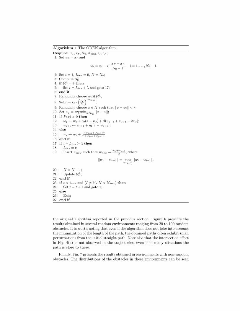
Algorithm 1 The ODEN algorithm.Require: xI , xF , N0, Nmax, rI , rF ;1: Set w0 = xI and
wi = xI + i · xF − xI
N0 − 1, i = 1, . . . , N0 − 1.
2: Set t = 1, Lins = 0, N = N0;3: Compute U t
U ;4: if U t
U = ∅ then5: Set t = Lins + λ and goto 17;6: end if7: Randomly choose wi ∈ U t
U ;
8: Set r = rI ·(
rFrI
)t/tmax;
9: Randomly choose x ∈ X such that ‖x− wi‖ < r;10: Set wj = arg minw∈Ut
U‖x− w‖;
11: if F (x) > 0 then12: wj ← wj + η0(x− wj) + β(wj−1 + wj+1 − 2wj);13: wj±1 ← wj±1 + η1(x− wj±1);14: else15: wj ← wj + α
(wj+1+wj−1)⊥
‖wj+1+wj−1‖;
16: end if17: if t− Lins ≥ λ then18: Lins = t;19: Insert wnew such that wnew =
wk+wk+12
, where
‖wk − wk+1‖ = maxwi∈Ut
U
‖wi − wi+1‖.
20: N = N + 1;21: Update U t
U ;22: end if23: if t < tmax and (I 6= ∅ ∨N < Nmax) then24: Set t = t+ 1 and goto 7;25: else26: Exit;27: end if
the original algorithm reported in the previous section. Figure 6 presents theresults obtained in several random environments ranging from 20 to 100 randomobstacles. It is worth noting that even if the algorithm does not take into accountthe minimization of the length of the path, the obtained paths often exhibit smallperturbations from the initial straight path. Note also that the intersection effectin Fig. 4(a) is not observed in the trajectories, even if in many situations thepath is close to these.
Finally, Fig. 7 presents the results obtained in environments with non-randomobstacles. The distributions of the obstacles in these environments can be seen

(a) No obstacles. (b) 25 obstacles.
Fig. 5. Trajectories obtained with ODEN in the environments of Fig. 3, correspondingto 100% and approximately 77% of free-space.
(a) 20 obstacles. (b) 40 obstacles. (c) 60 obstacles.
(d) 80 obstacles. (e) 100 obstacles.
Fig. 6. Sample network outlines obtained with ODEN in five random environmentswith diverse number of obstacles, respectively corresponding to approximately 82%,64%, 46%, 28% and 10% of free-space.
(a) (b) (c)
Fig. 7. Trajectory obtained with ODEN in environments with non-random obstacles.
as possible worst-case situations for the algorithm. Notice that the algorithm is,in fact, able to deliver the expected collision-free paths.
We note that, in the first set of environments, the algorithm is generallyable to deliver a solution and stop within few iterations. This is in clear contrastwith the original method, which would run for a predefined number of iterations.Also, ODEN generally performs better on more sparse environments than in en-vironments with little free space. This is easily explained if we consider that the
algorithm proceeds by sampling the space around the network and pulling thenetwork toward free-space and away from the obstacles. If few sample points liein free space, more iterations will be required for the algorithm to find a properpath. Finally, “thin” obstacles may be hard to sample and, therefore, hard toavoid. We produce one further experiment to test the performance of the algo-rithm when a single thin, long obstacle is found in the environment. The resultis presented in Fig. 7(c). Even though the environment has a single obstacle andis, in general, a sparse environment, the algorithm took a considerable numberof iterations (≈ 720) before a solution was found.
4 MODEN: ODEN in Multi-path Domains
We now address the more complex problem of connecting n pairs of towers in acommon environment. Given the positions in configuration space for all towers inthe set, we are interested in determining individual paths joining the two towersin each of the n pairs, so that the paths are non-intersecting. The requirementfor non-intersecting paths is mainly to avoid undesirable interference betweenthe corresponding communication channels. We henceforth refer to the nodesbetween the pair of towers i as the network ENi and refer to the positions of thecorresponding towers as the “initial” and “final” points of ENi (with no particularconvention as to which is the initial and which is the final).
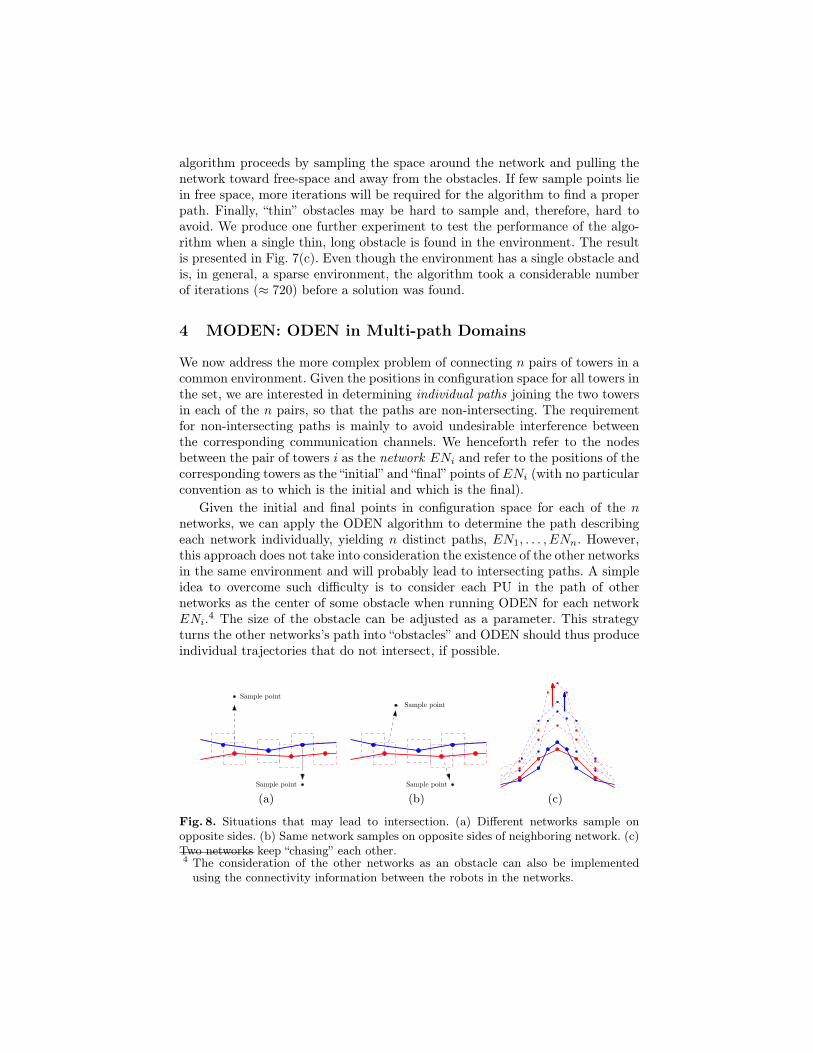
Given the initial and final points in configuration space for each of the nnetworks, we can apply the ODEN algorithm to determine the path describingeach network individually, yielding n distinct paths, EN1, . . . , ENn. However,this approach does not take into consideration the existence of the other networksin the same environment and will probably lead to intersecting paths. A simpleidea to overcome such difficulty is to consider each PU in the path of othernetworks as the center of some obstacle when running ODEN for each networkENi.4 The size of the obstacle can be adjusted as a parameter. This strategyturns the other networks’s path into “obstacles” and ODEN should thus produceindividual trajectories that do not intersect, if possible.
Sample point
Sample point
(a)
Sample point
Sample point
(b) (c)
Fig. 8. Situations that may lead to intersection. (a) Different networks sample onopposite sides. (b) Same network samples on opposite sides of neighboring network. (c)Two networks keep “chasing” each other.4 The consideration of the other networks as an obstacle can also be implementedusing the connectivity information between the robots in the networks.
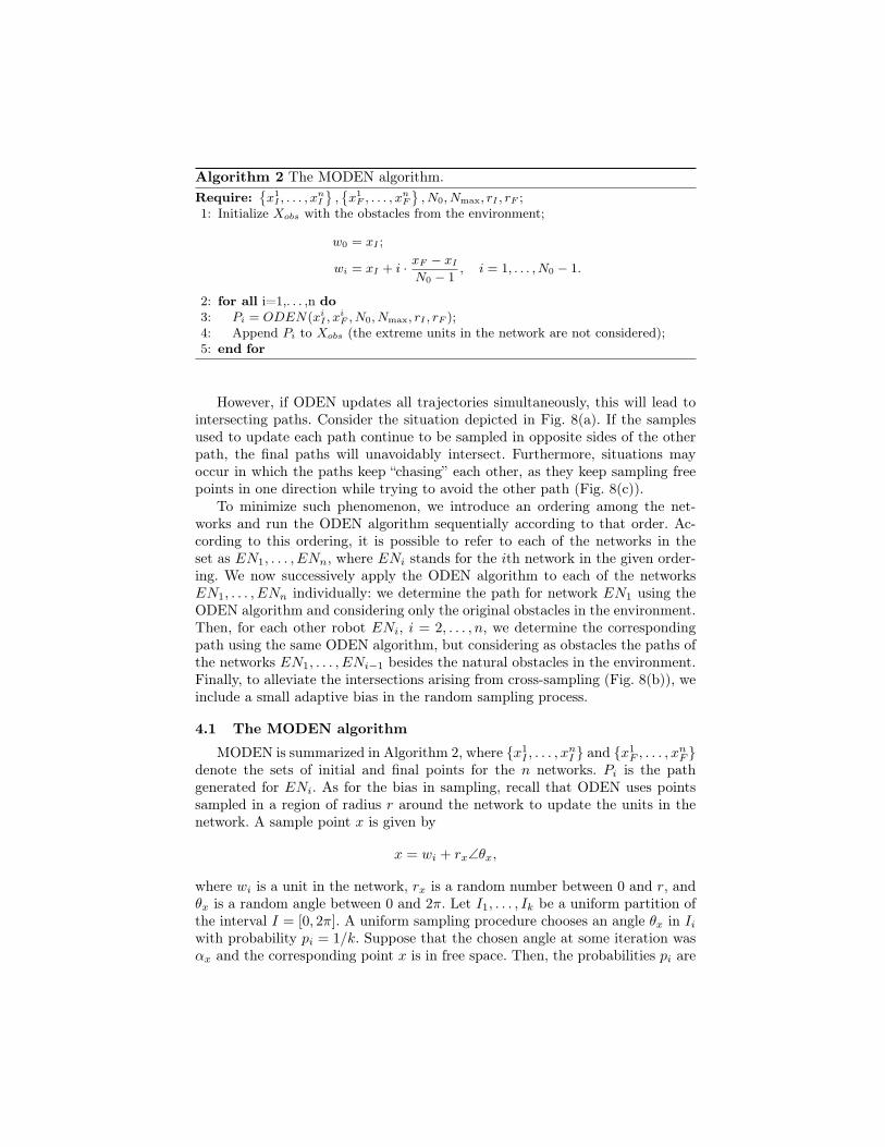
Algorithm 2 The MODEN algorithm.Require:
{x1
I , . . . , xnI
},{x1
F , . . . , xnF
}, N0, Nmax, rI , rF ;
1: Initialize Xobs with the obstacles from the environment;
w0 = xI ;
wi = xI + i · xF − xI
N0 − 1, i = 1, . . . , N0 − 1.
2: for all i=1,. . . ,n do3: Pi = ODEN(xi
I , xiF , N0, Nmax, rI , rF );
4: Append Pi to Xobs (the extreme units in the network are not considered);5: end for
However, if ODEN updates all trajectories simultaneously, this will lead tointersecting paths. Consider the situation depicted in Fig. 8(a). If the samplesused to update each path continue to be sampled in opposite sides of the otherpath, the final paths will unavoidably intersect. Furthermore, situations mayoccur in which the paths keep “chasing” each other, as they keep sampling freepoints in one direction while trying to avoid the other path (Fig. 8(c)).
To minimize such phenomenon, we introduce an ordering among the net-works and run the ODEN algorithm sequentially according to that order. Ac-cording to this ordering, it is possible to refer to each of the networks in theset as EN1, . . . , ENn, where ENi stands for the ith network in the given order-ing. We now successively apply the ODEN algorithm to each of the networksEN1, . . . , ENn individually: we determine the path for network EN1 using theODEN algorithm and considering only the original obstacles in the environment.Then, for each other robot ENi, i = 2, . . . , n, we determine the correspondingpath using the same ODEN algorithm, but considering as obstacles the paths ofthe networks EN1, . . . , ENi−1 besides the natural obstacles in the environment.Finally, to alleviate the intersections arising from cross-sampling (Fig. 8(b)), weinclude a small adaptive bias in the random sampling process.
4.1 The MODEN algorithm
MODEN is summarized in Algorithm 2, where {x1I , . . . , x
nI } and {x1
F , . . . , xnF }
denote the sets of initial and final points for the n networks. Pi is the pathgenerated for ENi. As for the bias in sampling, recall that ODEN uses pointssampled in a region of radius r around the network to update the units in thenetwork. A sample point x is given by
x = wi + rx∠θx,
where wi is a unit in the network, rx is a random number between 0 and r, andθx is a random angle between 0 and 2π. Let I1, . . . , Ik be a uniform partition ofthe interval I = [0, 2π]. A uniform sampling procedure chooses an angle θx in Iiwith probability pi = 1/k. Suppose that the chosen angle at some iteration wasαx and the corresponding point x is in free space. Then, the probabilities pi are
(a) (b) (c)
Fig. 9. Trajectories obtained for 2 networks in different environments.
(a) (b) (c)
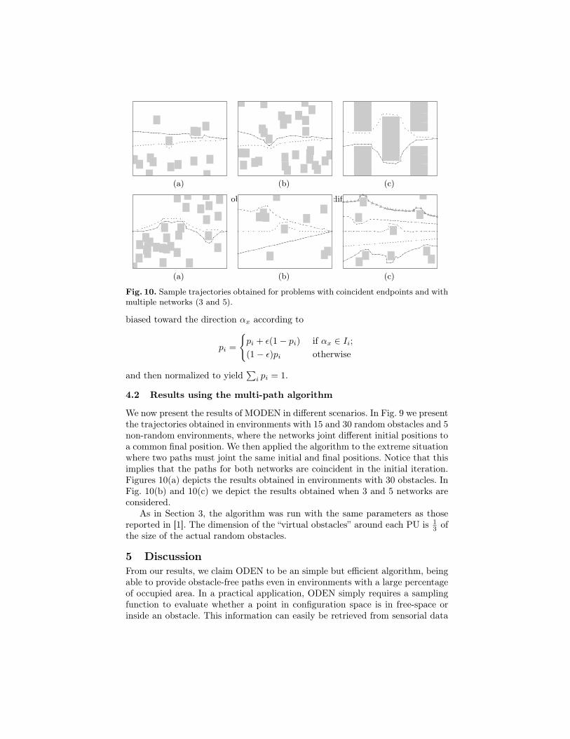
Fig. 10. Sample trajectories obtained for problems with coincident endpoints and withmultiple networks (3 and 5).
biased toward the direction αx according to
pi =
{pi + ε(1− pi) if αx ∈ Ii;(1− ε)pi otherwise
and then normalized to yield∑
i pi = 1.
4.2 Results using the multi-path algorithm
We now present the results of MODEN in different scenarios. In Fig. 9 we presentthe trajectories obtained in environments with 15 and 30 random obstacles and 5non-random environments, where the networks joint different initial positions toa common final position. We then applied the algorithm to the extreme situationwhere two paths must joint the same initial and final positions. Notice that thisimplies that the paths for both networks are coincident in the initial iteration.Figures 10(a) depicts the results obtained in environments with 30 obstacles. InFig. 10(b) and 10(c) we depict the results obtained when 3 and 5 networks areconsidered.
As in Section 3, the algorithm was run with the same parameters as thosereported in [1]. The dimension of the “virtual obstacles” around each PU is 1
3 ofthe size of the actual random obstacles.
5 DiscussionFrom our results, we claim ODEN to be an simple but efficient algorithm, beingable to provide obstacle-free paths even in environments with a large percentageof occupied area. In a practical application, ODEN simply requires a samplingfunction to evaluate whether a point in configuration space is in free-space orinside an obstacle. This information can easily be retrieved from sensorial data

and makes this method simple to implement. On the other hand, the samplingmechanism supporting ODEN implies that the algorithm is less effective in en-vironments with little free-space or with very thin obstacles. In the former case,it will be hard to sample points in free-space to pull the network away from theobstacles. In the latter case, it will be hard to sample the obstacles so as to drivethe network away from them.
MODEN extends the simple principle behind ODEN to multi-path scenar-ios, while remaining a local method driven by obstacles. MODEN attests theapplicability of ODEN in more complex problems and suitably illustrates theeffectiveness of ODEN’s underlying working principle. Nevertheless, and in spiteof the encouraging results, we should remark that if the initial straight-line pathof the several networks intersects, it is generally not possible to ensure a non-intersecting solution. And it may also happen that the path for the first networkrenders the task of finding an obstacle and intersection-free path infeasible.
As future work, it would be interesting to explore the use of richer attractionfunctions F . If the attraction function F is more than an “obstacle-indicator”,the algorithm may use the extra information to drive the updates in a moreinformed fashion and thus improve its performance.
Another interesting discussion arises from the consideration of ODEN andMODEN as path planning algorithms, in which each network corresponds to theactual path of one robot. In the particular case of MODEN, the requirementof non-intersecting paths in multi-robot path planning is not such a usual ap-proach, as more elaborate ways exist to coordinate multiple robots wandering ina common environment (see, for example, the approaches in [9,10]). Nevertheless,non-intersecting paths alleviate the need for any knowledge of the robot dynam-ics/communication capabilities. The paths generated by the algorithm wouldbe immediately usable by the robots, without considering any coordination orsynchronization mechanism to prevent on-path collisions.
(a) ODEN. (b) PRM.
Fig. 11. Trajectories obtained with ODEN and PRM.
We note that, as with ODEN, environments with little free space also causedifficulties to probabilistic path planning methods such as PRMs [11]. Also, thefact that ODEN uses all nodes in defining its path implies that, in general itwill be able to locally adjust to the obstacles, producing potentially shorterpaths. Figure 11 compares the paths obtained with ODEN and PRM in anenvironment with 60 random obstacles. A more extensive comparison of the
performance ODEN againsta that of other state-of-the-art planning methods isstill necessary to further understand the applicability of ODEN in more generalscenarios than those considered here.
References
1. Moreno, J., Castro, M.: Heuristic algorithm for robot path planning based on agrowing elastic net. In: 12th Portuguese Conf. Artificial Intelligence. (2005) 447–454
2. Ludwig, L., Gini, M.: Robotic swarm dispersion using wireless intensity signals.In: Int. Symp. Distributed Autonomous Robotic Systems. (2006) 135–144
3. Howard, A., Siddiqi, S., Sukhatme, G.: An experimental study of localization usingwireless ethernet. In: 4th Int. Conf. Field and Service Robotics. (2003)
4. Peng, C., Shen, G., Han, Z., Zhang, Y., Li, Y., Tan., K.: A beepbeep rangingsystem on mobile phones. In: ACM Conf. Embedded Networked Sensor Systems.(2007)
5. Poduri, S., Sukhatme, G.: Constrained coverage for mobile sensor networks. In:IEEE Int. Conf. Robotics and Automation. (2004) 165–171
6. Priyantha, N., Chakraborty, A., Balakrishnan, H.: The cricket location-supportsystem. In: 6th ACM Conf. Mobile Computing and Networking. (2000) 32–43
7. Ziparo, V., Kleiner, A., Nebel, B., Nardi, D.: RFID-based exploration for largerobot teams. In: IEEE Int. Conf. Robotics and Automation. (2007) 4606–4613
8. Reich, J., Misra, V., Rubenstein, D., Zussman, G.: Spreadable connected auto-nomic networks (SCAN). Tech. Rep. CUCS-016-08, CS Dep., Columbia Univ.(2008)
9. Bennewitz, M., Burgard, W., Thrun, S.: Optimizing schedules for prioritized pathplanning of multi-robot systems. In: IEEE Int. Conf. on Robotics and Automation.(2001) 27–276
10. Švestka, P., Overmars, M.: Coordinated path planning for multiple robots.Robotics and Autonomous Systems 23 (1998) 125–152
11. Kavraki, L., Švestka, P., Latombe, J., Overmars, M.: Probabilistic roadmaps forpath planning in high-dimensional configuration spaces. IEEE Trans. Robotics andAutomation RA-12(4) (1996) 566–580