modern robotics - mech
TRANSCRIPT
MODERN ROBOTICS
MECHANICS, PLANNING, AND CONTROL
Practice Exercises
Contributions from Tito Fernandez, Kevin Lynch, Huan Weng, and ZackWoodruff
November 4, 2018
This is a supplemental document to
Modern RoboticsMechanics, Planning, and Control
Kevin M. Lynch and Frank C. ParkCambridge University Press, 2017
Original material from this document may be reused provided proper citationis given. More information on the book, including a downloadable preprint,software, videos, online courses, and a feedback form can be found at http:
//modernrobotics.org. Comments are welcome!

Contents
1 Introduction 1
2 Practice Exercises on Configuration Space 32.1 Practice Exercises . . . . . . . . . . . . . . . . . . . . . . . . . . 32.2 Solutions . . . . . . . . . . . . . . . . . . . . . . . . . . . . . . . 9
3 Practice Exercises on Rigid-Body Motions 153.1 Practice Exercises . . . . . . . . . . . . . . . . . . . . . . . . . . 153.2 Solutions . . . . . . . . . . . . . . . . . . . . . . . . . . . . . . . 25
4 Practice Exercises on Forward Kinematics 314.1 Practice Exercises . . . . . . . . . . . . . . . . . . . . . . . . . . 314.2 Solutions . . . . . . . . . . . . . . . . . . . . . . . . . . . . . . . 35
5 Practice Exercises on Velocity Kinematics and Statics 395.1 Practice Exercises . . . . . . . . . . . . . . . . . . . . . . . . . . 395.2 Solutions . . . . . . . . . . . . . . . . . . . . . . . . . . . . . . . 43
6 Practice Exercises on Inverse Kinematics 476.1 Practice Exercises . . . . . . . . . . . . . . . . . . . . . . . . . . 476.2 Solutions . . . . . . . . . . . . . . . . . . . . . . . . . . . . . . . 50
7 Practice Exercises on Kinematics of Closed Chains 51
8 Practice Exercises on Dynamics of Open Chains 538.1 Practice Exercises . . . . . . . . . . . . . . . . . . . . . . . . . . 538.2 Solutions . . . . . . . . . . . . . . . . . . . . . . . . . . . . . . . 59
i
ii Contents
9 Practice Exercises on Trajectory Generation 679.1 Practice Exercises . . . . . . . . . . . . . . . . . . . . . . . . . . 679.2 Solutions . . . . . . . . . . . . . . . . . . . . . . . . . . . . . . . 69
Practice exercises for Modern Robotics, Lynch and Park, Cambridge U. Press, 2017. http://modernrobotics.org

Chapter 1
Introduction
These exercises are designed to give you practice with the concepts, the calcula-tions, and the software associated with the book. To get the most out of thesepractice exercises, you are strongly encouraged not to look at the solutions untilyou have given your best effort to solve them. You are more likely to retainwhat you have learned when you work through the problem yourself instead ofjust reading the solution.
1

2
Practice exercises for Modern Robotics, Lynch and Park, Cambridge U. Press, 2017. http://modernrobotics.org
Chapter 2
Practice Exercises onConfiguration Space
2.1 Practice Exercises
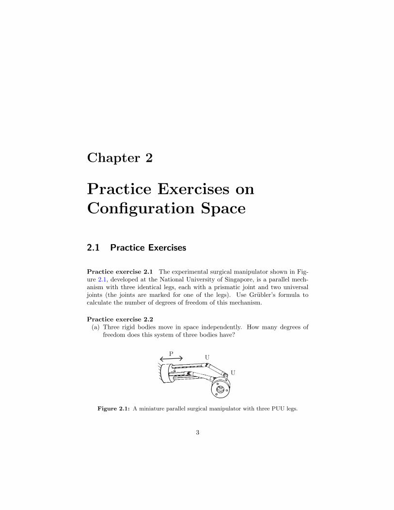
Practice exercise 2.1 The experimental surgical manipulator shown in Fig-ure 2.1, developed at the National University of Singapore, is a parallel mech-anism with three identical legs, each with a prismatic joint and two universaljoints (the joints are marked for one of the legs). Use Grubler’s formula tocalculate the number of degrees of freedom of this mechanism.
Practice exercise 2.2(a) Three rigid bodies move in space independently. How many degrees of
freedom does this system of three bodies have?
PU
U
Figure 2.1: A miniature parallel surgical manipulator with three PUU legs.
3
4 2.1. Practice Exercises
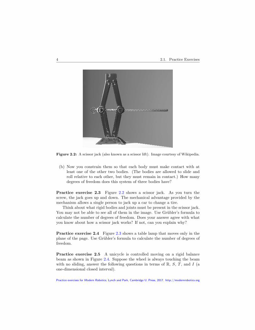
Figure 2.2: A scissor jack (also known as a scissor lift). Image courtesy of Wikipedia.
(b) Now you constrain them so that each body must make contact with atleast one of the other two bodies. (The bodies are allowed to slide androll relative to each other, but they must remain in contact.) How manydegrees of freedom does this system of three bodies have?
Practice exercise 2.3 Figure 2.2 shows a scissor jack. As you turn thescrew, the jack goes up and down. The mechanical advantage provided by themechanism allows a single person to jack up a car to change a tire.
Think about what rigid bodies and joints must be present in the scissor jack.You may not be able to see all of them in the image. Use Grubler’s formula tocalculate the number of degrees of freedom. Does your answer agree with whatyou know about how a scissor jack works? If not, can you explain why?
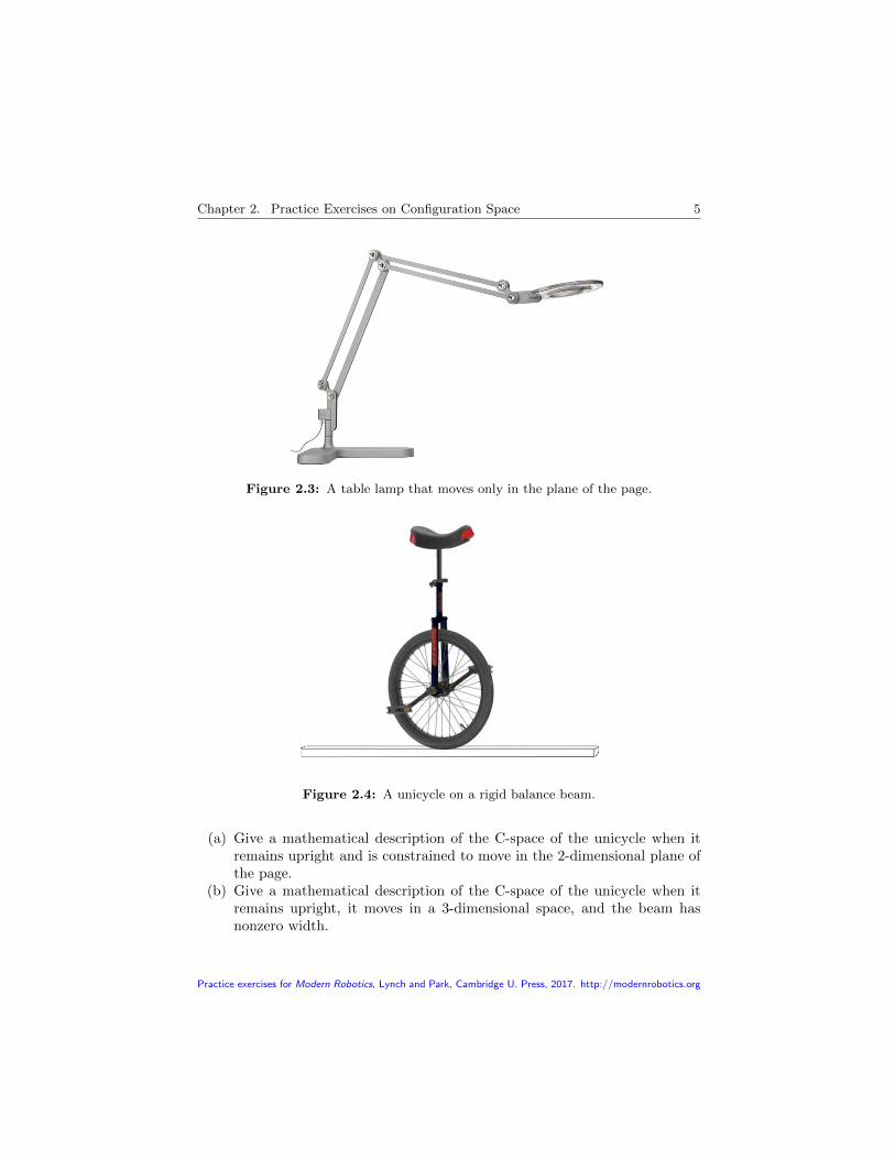
Practice exercise 2.4 Figure 2.3 shows a table lamp that moves only in theplane of the page. Use Grubler’s formula to calculate the number of degrees offreedom.
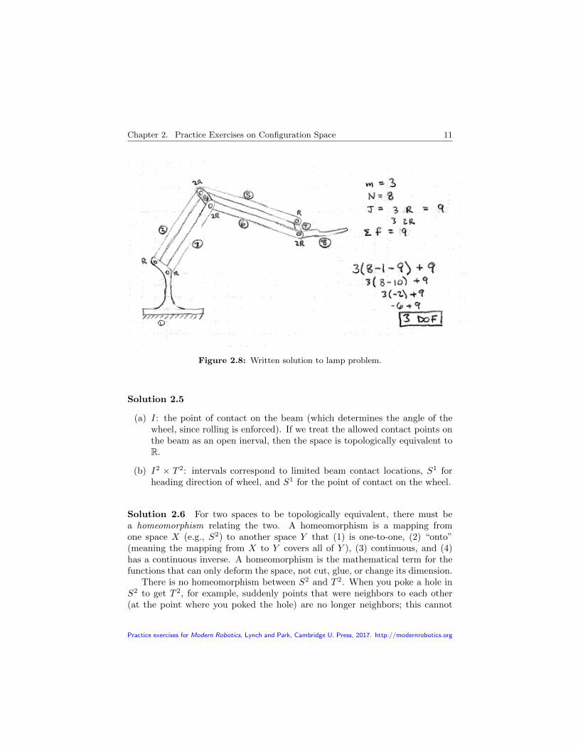
Practice exercise 2.5 A unicycle is controlled moving on a rigid balancebeam as shown in Figure 2.4. Suppose the wheel is always touching the beamwith no sliding, answer the following questions in terms of R, S, T , and I (aone-dimensional closed interval).
Practice exercises for Modern Robotics, Lynch and Park, Cambridge U. Press, 2017. http://modernrobotics.org
Chapter 2. Practice Exercises on Configuration Space 5
Figure 2.3: A table lamp that moves only in the plane of the page.
Figure 2.4: A unicycle on a rigid balance beam.
(a) Give a mathematical description of the C-space of the unicycle when itremains upright and is constrained to move in the 2-dimensional plane ofthe page.
(b) Give a mathematical description of the C-space of the unicycle when itremains upright, it moves in a 3-dimensional space, and the beam hasnonzero width.
Practice exercises for Modern Robotics, Lynch and Park, Cambridge U. Press, 2017. http://modernrobotics.org

6 2.1. Practice Exercises
Practice exercise 2.6 Explain why S1 × S1 = T 2, not S2. In other words,explain why the C-space of a spherical pendulum (S2) is not topologically equiv-alent to the C-space of a 2R robot (T 2), even though the configurations of bothwould typically be described by two angles. If you think the C-space of a 2Rrobot is topologically equivalent (homeomorphic) to S2, propose a continuousmapping between points on a sphere and the independent joint angles of a 2Rrobot.
Practice exercise 2.7 Assume your arm has 7 dof and you constrain yourhand to be at a fixed configuration (e.g., your palm is flat against a table).
(a) What is an explicit representation of the arm’s configuration?(b) What is an implicit representation?(c) What does the set of feasible configurations look like in the 7-dimensional
configuration space of the unconstrained arm?
Practice exercise 2.8 Imagine a C-space described as a circle in an (x, y)plane, of radius 2 centered at (3, 0). What is an implicit representation ofthis one-dimensional C-space? If you were to decide to parameterize the one-dimensional C-space by the single parameter θ, give a mapping from θ to (x, y).
Practice exercise 2.9 Consider the 2D quadcopter and rod shown in Fig-ure 2.5. The rod is attached to the quadcopter by a revolute joint, and youare given the task of balancing the rod upright (a flying version of the classiccart pendulum problem). Assume the configuration of the quadcopter center isdescribed by (xq, yq, θq) and the configuration of the rod center is described as(xr, yr, θr) where θq and θr are measured with respect to the world x axis. Thelength of the rod is 2l and the height and width of the quadcopter body are 2hand 2w respectively.
(a) Solve for the configuration constraints that keep the rod and quadcopterconnected.
(b) Express these as a Pfaffian constraint where q = [xq yq θq xr yr θr]T.
Practice exercise 2.10 Consider the parallel SCARA robot shown in Fig-ure 2.6. The robot is controlled by two rotational motors located in the base,and one rotational and one prismatic motor at the end effector. Assume eachof the links of the parallel mechanism are length 1 m, the prismatic joint has amaximum travel of 1 m, and the separation distance of the base motors is 0.5 m.
Practice exercises for Modern Robotics, Lynch and Park, Cambridge U. Press, 2017. http://modernrobotics.org

Chapter 2. Practice Exercises on Configuration Space 7
x
y
Figure 2.5: 2D quadcopter balancing a rod
Assume no collisions between the links, and that the end effector y-coordinateis constrained to be greater than zero.
(a) Sketch the workspace of the end effector.(b) What are some benefits and drawbacks of making a parallel rather than
a serial SCARA robot?
Practice exercises for Modern Robotics, Lynch and Park, Cambridge U. Press, 2017. http://modernrobotics.org

8 2.1. Practice Exercises
x
y
1 1
1 1
0.5
x z
y
Figure 2.6: Parallel SCARA robot and a skeleton top view.
Practice exercises for Modern Robotics, Lynch and Park, Cambridge U. Press, 2017. http://modernrobotics.org

Chapter 2. Practice Exercises on Configuration Space 9
2.2 Solutions
Solution 2.1 There are N = 8 links (two links in each leg, ground, andthe moving platform). There are J = 9 joints (three prismatic joints and sixuniversal joints). The joints have a total of 3(1) + 6(2) = 15 degrees of freedom.By Grubler’s formula,
dof = 6(8− 1− 9) + 15 = 3.
Solution 2.2(a) 3(6) = 18.(b) The system of three bodies is now subject to two equality constraints. For
example, if the three bodies are called A, B, and C, the constraints couldbe written as the two equations dist(A,B) = 0 and dist(B,C) = 0. Thesetwo constraints subtract two degrees of freedom, so there are 16 degreesof freedom now.
Solution 2.3 See Figure 2.7 for work. Note that there are two extra crosspieces behind the two side joints that are not visible from the image. Theresult of Grubler’s formula does NOT agree with the known solution of 1 DOF.This is due to the symmetry of this problem, causing certain constraints to notbe independent. Instead, the formula provides a lower bound, and the knownsolution of 1 DOF is indeed above that lower bound.
Practice exercises for Modern Robotics, Lynch and Park, Cambridge U. Press, 2017. http://modernrobotics.org

10 2.2. Solutions
Figure 2.7: Written solution to scissor jack problem.
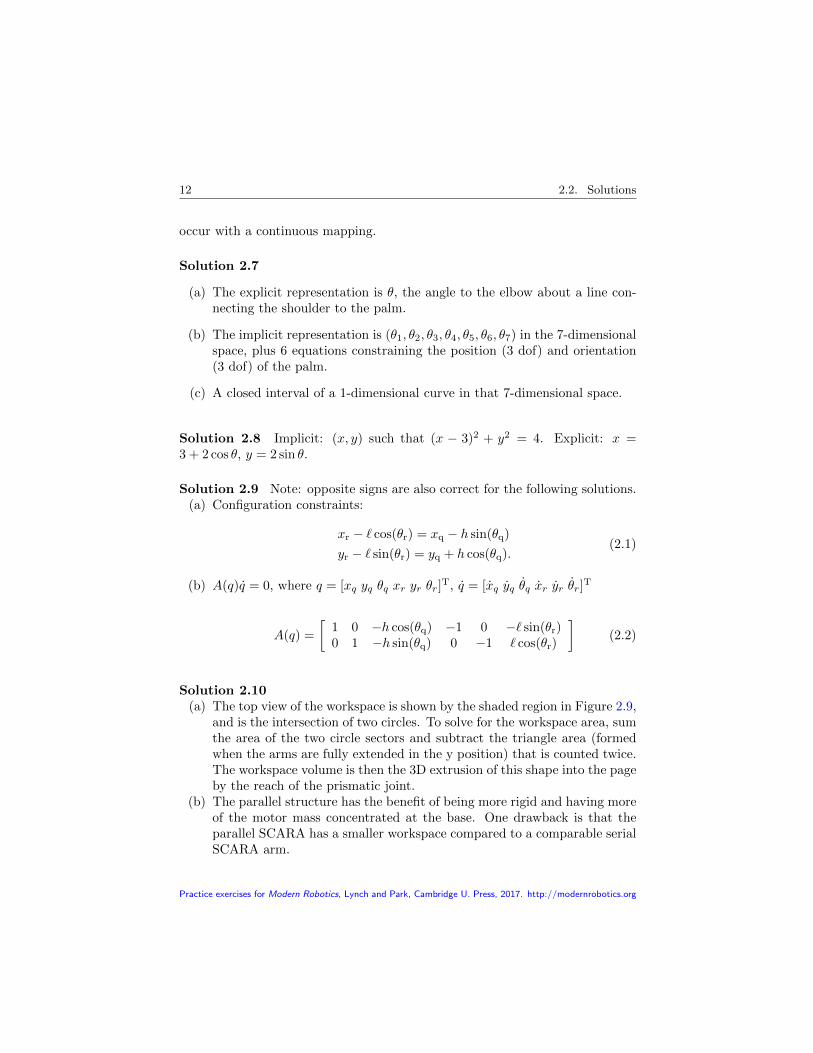
Solution 2.4 Despite all the links and revolute joints, this mechanical systembehaves similarly to a 3R robot arm, since each set of two revolute joints actsas a single hinge.
Practice exercises for Modern Robotics, Lynch and Park, Cambridge U. Press, 2017. http://modernrobotics.org
Chapter 2. Practice Exercises on Configuration Space 11
Figure 2.8: Written solution to lamp problem.
Solution 2.5
(a) I: the point of contact on the beam (which determines the angle of thewheel, since rolling is enforced). If we treat the allowed contact points onthe beam as an open inerval, then the space is topologically equivalent toR.
(b) I2 × T 2: intervals correspond to limited beam contact locations, S1 forheading direction of wheel, and S1 for the point of contact on the wheel.
Solution 2.6 For two spaces to be topologically equivalent, there must bea homeomorphism relating the two. A homeomorphism is a mapping fromone space X (e.g., S2) to another space Y that (1) is one-to-one, (2) “onto”(meaning the mapping from X to Y covers all of Y ), (3) continuous, and (4)has a continuous inverse. A homeomorphism is the mathematical term for thefunctions that can only deform the space, not cut, glue, or change its dimension.
There is no homeomorphism between S2 and T 2. When you poke a hole inS2 to get T 2, for example, suddenly points that were neighbors to each other(at the point where you poked the hole) are no longer neighbors; this cannot
Practice exercises for Modern Robotics, Lynch and Park, Cambridge U. Press, 2017. http://modernrobotics.org
12 2.2. Solutions
occur with a continuous mapping.
Solution 2.7
(a) The explicit representation is θ, the angle to the elbow about a line con-necting the shoulder to the palm.
(b) The implicit representation is (θ1, θ2, θ3, θ4, θ5, θ6, θ7) in the 7-dimensionalspace, plus 6 equations constraining the position (3 dof) and orientation(3 dof) of the palm.
(c) A closed interval of a 1-dimensional curve in that 7-dimensional space.
Solution 2.8 Implicit: (x, y) such that (x − 3)2 + y2 = 4. Explicit: x =3 + 2 cos θ, y = 2 sin θ.
Solution 2.9 Note: opposite signs are also correct for the following solutions.(a) Configuration constraints:
xr − ` cos(θr) = xq − h sin(θq)
yr − ` sin(θr) = yq + h cos(θq).(2.1)
(b) A(q)q = 0, where q = [xq yq θq xr yr θr]T, q = [xq yq θq xr yr θr]
T
A(q) =
[1 0 −h cos(θq) −1 0 −` sin(θr)0 1 −h sin(θq) 0 −1 ` cos(θr)
](2.2)
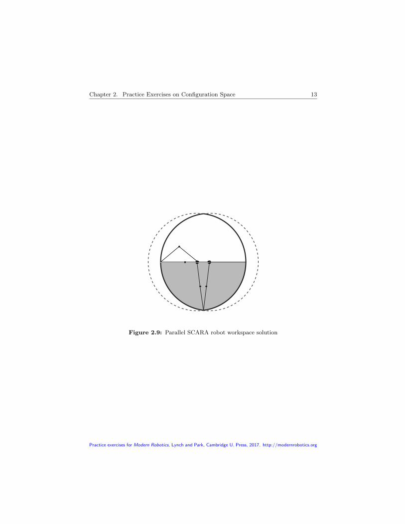
Solution 2.10(a) The top view of the workspace is shown by the shaded region in Figure 2.9,
and is the intersection of two circles. To solve for the workspace area, sumthe area of the two circle sectors and subtract the triangle area (formedwhen the arms are fully extended in the y position) that is counted twice.The workspace volume is then the 3D extrusion of this shape into the pageby the reach of the prismatic joint.
(b) The parallel structure has the benefit of being more rigid and having moreof the motor mass concentrated at the base. One drawback is that theparallel SCARA has a smaller workspace compared to a comparable serialSCARA arm.
Practice exercises for Modern Robotics, Lynch and Park, Cambridge U. Press, 2017. http://modernrobotics.org
Chapter 2. Practice Exercises on Configuration Space 13
Figure 2.9: Parallel SCARA robot workspace solution
Practice exercises for Modern Robotics, Lynch and Park, Cambridge U. Press, 2017. http://modernrobotics.org

14 2.2. Solutions
Practice exercises for Modern Robotics, Lynch and Park, Cambridge U. Press, 2017. http://modernrobotics.org

Chapter 3
Practice Exercises onRigid-Body Motions
3.1 Practice Exercises
Practice exercise 3.1 The mobile manipulator in Figure 3.1 needs to orientits gripper to grasp the block. For subsequent placement of the block, we havedecided that the orientation of the gripper relative to the block, when the grippergrasps the block, should be Reg. Our job is to determine the rotation operatorto apply to the gripper to achieve this orientation relative to the block.
Figure 3.1 shows the fixed world frame {a}, the mobile robot’s chassis frame{b}, the gripper frame {c}, the RGBD camera (color vision plus depth, like theKinect) frame {d}, and the object frame {e}. Because we put the camera at aknown location in space, we know Rad. The camera reports the configurationof {e} relative to {d}, so we know Rde. From the mobile robot’s localizationprocedure (e.g., vision-based localization or odometry) we know Rab. From therobot arm’s forward kinematics we know Rbc.
(a) In terms of the four known rotation matrices Rad, Rde, Rab, and Rbc, andusing only matrix multiplication and the transpose operation, express thecurrent orientation of the gripper relative to the block, Rec.
(b) To align the gripper properly, you could apply to it a rotation R1 expressedin terms of axes in the gripper’s {c} frame. What is R1, in terms of the fiveknown rotation matrices (Rad, Rde, Rab, Rbc, Reg), matrix multiplication,and transpose?
15

16 3.1. Practice Exercises
{a}
{b}
{c}{d}
}{e
Figure 3.1: The fixed world frame {a}, the mobile robot’s chassis frame {b}, thegripper frame {c}, the RGBD camera frame {d}, and the object frame {e}.
{s}xs
ys
zs
{b}
xb
yb
zb
2 cm
Figure 3.2: As the machine screw goes into a tapped hole, it advances linearly by4π mm every full rotation of the screw.
(c) The same rotation could be written R2, in terms of the axes of the frameof the mobile base {b}. What is R2?
Practice exercise 3.2 Figure 3.2 shows a screw, a frame {b}, and a frame{s}. The xb-axis of {b} is along the axis of the screw, and the origin of theframe {s} is displaced by 2 cm, along the yb-axis, from the {b} frame. Thezs-axis is aligned with xb and the xs-axis is aligned with zb.
Taking note of the direction of the screw’s threads, as the machine screw goes
Practice exercises for Modern Robotics, Lynch and Park, Cambridge U. Press, 2017. http://modernrobotics.org

Chapter 3. Practice Exercises on Rigid-Body Motions 17
{c}xc
yc
zc
(0, 3, 0)
45◦
Figure 3.3: A screw axis in the (yc, zc) plane.
into a tapped hole driven by a screwdriver rotating at 3 radians per second, whatis the screw’s twist expressed in {b}, Vb? What is the screw axis expressed in{b}, Sb? What is Vs? What is Ss? Give units as appropriate.
Practice exercise 3.3 A wrench F and a twist V are represented in {a} asFa and Va, respectively, and they are represented in {b} as Fb and Vb. Withoutconsulting any other source, and using the facts that (AB)T = BTAT, that theadjoint of the transformation matrix Tab can be used to change the frame ofrepresentation of a twist from the {a} frame to the {b} frame, and that thescalar power generated (or dissipated) by applying a wrench F along a twistV is independent of the frame of reference, show that Fa = [AdTba
]TFb. (Theability to derive this result is useful for your understanding of it.)
Practice exercise 3.4 Figure 3.3 shows a screw axis in the (yc, zc) plane, ata 45◦ angle with respect to the yc-axis. (The xc-axis points out of the page.)The screw axis passes through the point (0, 3, 0).
(a) If the pitch of the screw is h = 10 linear units per radian, what is thescrew axis Sc? Make sure you can also write this in its se(3) form [Sc],too.
(b) Using your answer to (a), if the speed of rotation about the screw axis isθ =√
2 rad/s, what is the twist Vc?(c) Using your answer to (a), if a frame initially at {c} rotates by θ = π/2
about the screw axis, yielding a new frame {c′}, what are the exponentialcoordinates describing the configuration of {c′} relative to {c}?
(d) What is Tcc′ , corresponding to the motion in part (c)?(e) Now imagine that the axis in Figure 3.3 represents a wrench: a linear force
along the axis and a moment about the axis (according to the right-handrule). The linear force in the direction of the axis is 20 and the momentabout the axis is 10. What is the wrench Fc?
Practice exercises for Modern Robotics, Lynch and Park, Cambridge U. Press, 2017. http://modernrobotics.org

18 3.1. Practice Exercises
{a}xa
ya
za
(−2, 1, 0)
screwaxis
Figure 3.4: A zero-pitch screw axis.
Practice exercise 3.5 Let Tsb ∈ SE(3) represent the configuration of theframe {b} relative to {s}. (We sometimes write this simply as T .) If {b}moves over time, you could represent its velocity as Tsb (or simply T ), the timederivative of Tsb. You should think of this velocity as a twist of the entire space(to which the moving frame is attached). But we know that the velocity shouldbe representable by only six values, and Tsb could have 12 unique nonzero values(the top three rows of the 4× 4 matrix; the bottom row will be all zeros, sincethe bottom row of a transformation matrix is always the constant [0 0 0 1]).
Instead, we could post-multiply Tsb by Tbs, i.e., Ts�bT�bs
= T T−1 = Tss. Thispost-multiplication has the effect of representing the velocity in the {s} frame,getting rid of the dependence on the current {b} frame. What do we call thequantity T T−1? How many values are needed to uniquely specify it?
We could also pre-multiply Tsb by Tbs to get Tb�sT�sb
= T−1T = Tbb. Thispre-multiplication has the effect of representing the velocity in the {b} frame,getting rid of the dependence on the {s} frame. What do we call the quantityT−1T?
Practice exercise 3.6 The zero-pitch screw axis in Figure 3.4, aligned withza, passes through the point (−2, 1, 0) in the {a} frame. What is the twist Va ifwe rotate about the screw axis at a speed θ = 5 rad/s?
Practice exercise 3.7 A wrench F is represented in the {c} frame as Fc. IfT1 = Tab is the configuration of the {b} frame relative to the {a} frame, andT2 = Tac is the configuration of the {c} frame relative to the {a} frame, express
Practice exercises for Modern Robotics, Lynch and Park, Cambridge U. Press, 2017. http://modernrobotics.org

Chapter 3. Practice Exercises on Rigid-Body Motions 19
za
xa
ya
{a}
{b} xb
yb
zb
Figure 3.5: A machine screw. Notice the direction of the threads.
Fb in terms of T1, T2, Fc, and any math operations you need.
Practice exercise 3.8 Let the orientation of {b} relative to {a} be
Rab =
1 0 00 0 −10 1 0
and a point p be represented in {a} as pa = (1, 2, 3). What is pb? (Give anumeric 3-vector.)
Practice exercise 3.9 Consider three frames, {a}, {b}, and {c}. You knowthe representations of these frames in terms of the others, e.g., Tab and Tbc(and therefore you can derive Tac and the inverses of these matrices). Give amathematical expression for Va, the twist (expressed in {a}) you would needto follow for t seconds to move the {b} frame to be coincident with the {c}frame. Or, if you prefer, give an expression for [Va], the se(3) representationof Va. Your answer should be symbolic (no numbers), and it should use t, anyof the transformation matrices you need, and any math operations you need.If it is helpful, you can use the operation vec : se(3) → R6 to get the vectorrepresentation of an element of se(3), e.g., vec([V]) = V.
Practice exercise 3.10 Figure 3.5 shows a machine screw. As it advancesinto a tapped hole, it moves 5 mm linearly for every radian of rotation. A frame{a} has its za-axis along the axis of the screw and its xa-axis out of the page.The frame {b} has its origin at pa = (0, 3,−2) mm and its orientation is shownin the figure (zb is out of the page). Use mm as your linear units and radiansas your angular units.
Practice exercises for Modern Robotics, Lynch and Park, Cambridge U. Press, 2017. http://modernrobotics.org

20 3.1. Practice Exercises
{b}x
yz
ωb
z x
y
{e}
Figure 3.6: Satellite rotating in space.
(a) What is the screw axis Sa corresponding to advancing into a tapped hole?Give a numerical 6-vector.
(b) What is the screw axis Sb? Give a numerical 6-vector.(c) What is [Sb]?(d) From the initial configuration Tab shown in the figure, the {b} frame fol-
lows the screw an angle θ, ending at the final configuration Tab′ . If wewrite Tab′ = TTab, what is T? Express this symbolically (don’t writenumbers), using any of Sa, Sb, θ, and any math operations you need.
(e) Referring to the previous question, if we instead write Tab′ = TabT , whatis T? Again, express this symbolically (don’t write numbers), using anyof Sa, Sb, θ, and any math operations you need.
Practice exercise 3.11 Consider the satellite and Earth shown in Figure 3.6.Let ωb = (0, 1, 1) be the angular velocity of the satellite expressed in the satellitebody frame {b}. Assume a fixed Earth frame {e} (a geocentric view of theuniverse like the ancient Greeks had).
(a) Solve for the coordinate axis velocities of {b} ( ˙xb, ˙yb, and ˙zb) representedin the {b} frame. Sketch the velocity vectors on the figure above to confirmthat your solutions make sense.
Practice exercises for Modern Robotics, Lynch and Park, Cambridge U. Press, 2017. http://modernrobotics.org

Chapter 3. Practice Exercises on Rigid-Body Motions 21
(b) The orientation of the {b} frame is equivalent to the {e} frame after ithas been rotated −90 degrees about its ze-axis. Solve for ωe, the satelliteangular velocity represented in {e}. Sketch the velocity vectors on thefigure above to confirm that your solution makes sense.
(c) Solve for Reb, the time derivative of the body orientation expressed in {e}.(d) Give the so(3) representation of the angular velocity in both the Earth
and the body frame.
Practice exercise 3.12 Consider again the satellite and Earth shown in Fig-ure 3.6.
(a) If the given rotational velocity ωb = (0, 1, 1) was instead the exponentialcoordinates for a rotation, solve for the axis-angle representation and thecorresponding rotation matrix.
(b) After rotating and orbiting the Earth for some time, the relative orienta-tion of the Earth and satellite is given as
Reb′ =
0 −√
2/2√
2/21 0 0
0√
2/2√
2/2
.
Find the axis-angle representation that describes the rotation from theinitial body frame {b} to the new body frame {b’}.
Practice exercise 3.13 Consider the scene in Figure 3.7 of a once peacefulpark overrun by robots. Frames are shown attached to the tree {t}, robot chassis{c}, manipulator {m}, and quadcopter {q}. The distances shown in the figureare d1 = 4 m, d2 = 3 m, d3 = 6 m, d4 = 5 m, d5 = 3 m. The manipulator is at aposition pcm = (0, 2, 1) m relative to the chassis frame {c}, and {m} is rotatedfrom {c} by 45 degrees about the xc-axis.
(a) Give the transformation matrices representing the quadcopter frame {q},chassis frame {c}, and manipulator frame {m} in the tree frame {t}.
(b) Assume that the position controller for the manipulator on the mobilerobot is referenced to the chassis frame {c}. What position should youcommand the gripper to go to if you would like to snatch the quadcopterout of the sky?
(c) You are tasked to move the mobile robot so that the chassis origin isdirectly underneath the quadcopter and its frame is aligned with the treeframe. Assume the mobile robot chassis controller takes transformationmatrices in the chassis frame as inputs. What tranformation should youcommand the robot to follow?
Practice exercises for Modern Robotics, Lynch and Park, Cambridge U. Press, 2017. http://modernrobotics.org

22 3.1. Practice Exercises
d1
d2
d4
d5
d3
p
xy
z{c} x
yz
{m}
{q} x
y
z
{t}x
yz
Figure 3.7: A tree, mobile manipulator, and flying robot in a park and the corre-sponding reference frames.
Practice exercise 3.14 Consider the scene in Figure 3.8 of a quadcopter {q}flying near a tree {t} and house {h}. The quadcopter is at a position ptq = (10,5, 5) m expressed in the tree frame {t}, and the house is at a position pth =(0, 10, 10) m expressed in the tree frame {t}. The quadcopter is flying upwardswith a velocity of 1 m/s, and rotating with a velocity of 1 rad/s.
(a) Calculate the quadcopter’s twist in {q} and {t}.(b) Use the adjoint map to express the twist in the house frame {h}.
Practice exercise 3.15 Consider the cube with side lengths l = 2 m and theant shown in Figure 3.9. Frames {b} and {c} show the ant at the midpoint ofthe cube edges.
(a) Solve for the screw axis Sb and angle θ corresponding to the transformation
Practice exercises for Modern Robotics, Lynch and Park, Cambridge U. Press, 2017. http://modernrobotics.org

Chapter 3. Practice Exercises on Rigid-Body Motions 23
{h} x
yz
{q} x
y
z
{t}x
yz
ωq
vq
Figure 3.8: A tree, and flying robot in a park and the corresponding reference frames.
{w}x
yz
{b}x
yz
{c}x
y
z
l
l
l
Figure 3.9: An ant shown at different positions on a cube.
from {b} to {c}.(b) Sketch the location of the screw axis on the figure.
Practice exercises for Modern Robotics, Lynch and Park, Cambridge U. Press, 2017. http://modernrobotics.org

24 3.1. Practice Exercises
{t}x
yz
{b}x
y
z
wind
Figure 3.10: A tree and a frame attached to its branch.
(c) Use the appropriate adjoint map to find Sw, the screw axis representationin the {w} frame.
(d) How could you solve for Sw without using the adjoint map?
Practice exercise 3.16 Consider the scene in Figure 3.10 of a tree {t} and aframe {b} attached to its branch. The figure shows a strong wind that appliesa force of 100 N at the center of frame {b}. Assume the branch has a mass of50 kg centered at frame {b} as well. The position of the branch frame {b} inthe tree frame {t} is ptb = (2, 1, 3) m.
(a) What is the wrench Fb due to the wind and the branch’s weight?(b) What is this wrench in the tree frame {t}?
Practice exercises for Modern Robotics, Lynch and Park, Cambridge U. Press, 2017. http://modernrobotics.org

Chapter 3. Practice Exercises on Rigid-Body Motions 25
3.2 Solutions
Solution 3.1
(a)
Rec = RedRdaRabRbc
= RTdeR
TadRabRbc.
(b)
RecR1 = Reg → R1 = RTecReg
= (RTdeR
TadRabRbc)
TReg
= RTbcR
TabRadRdeReg (= Rcg).
(c)
R2 = RbcR1 = RbcRcg = RbcRTbcR
TabRadRdeReg = RT
abRadRdeReg (= Rbg).
Solution 3.2 The threads of this screw are the typical right-handed threads,which means that the screw, when viewed from the top, rotates clockwise whenit advances into a tapped hole. In other words, the fingers of your right handcurl in the direction of rotation of the screw when your right thumb pointsdownward on the page, in the negative direction of the upward-pointing xb-axis. Since the screwdriver rotates at 3 rad/s, the screw also rotates at 3 rad/s,so the angular component of the twist, expressed in {b}, is ωb = (−3 rad/s, 0, 0).Since radians and seconds are the SI units for angle and time, respectively, youcould write (−3, 0, 0) and assume the default SI units. You could also write(−3(180/π) deg/s, 0, 0), but that would be unusual.
The pitch of the screw is 4π mm per revolution, or 2 mm/rad. So asthe screw is rotated at 3 rad/s, it moves linearly in the −xb direction at(2 mm/rad)(3 rad/s) = 6 mm/s. So the linear component of the twist ex-pressed in {b} is (−6 mm/s, 0, 0), or, in SI units, vb = (−0.006 m/s, 0, 0). So,in SI units, the entire twist is Vb = (ωb, vb) = (−3, 0, 0,−0.006, 0, 0).
The corresponding screw axis expressed in {b} is the normalized version ofVb where the magnitude of the angular velocity is unit. The magnitude of ωbis 3, so divide the twist by 3 to get Sb = (−1, 0, 0,−0.002, 0, 0). We can writeVb = Sbθ where θ = ‖ωb‖ = 3.
Practice exercises for Modern Robotics, Lynch and Park, Cambridge U. Press, 2017. http://modernrobotics.org
26 3.2. Solutions
The screw axis could also be represented in the {b} frame by the collection{qb, sb, h}, where a point qb on the axis is (0, 0, 0) (expressed in {b}), the axisdirection is sb = (−1, 0, 0), and the pitch is h = 0.002.
In the {s} frame, the axis of rotation is aligned with the −zs-axis, so ωs =(0, 0,−3). A point at the origin of {s}, rigidly attached to the advancing screw,has a downward linear component of −0.006 m/s in the −zs direction (i.e.,(0, 0,−0.006)) from the downward motion of the screw. But it also has a linearcomponent in the −xs direction from the rotation of the screw. The point at theorigin of {s} can be expressed as qb = (0, 0.02, 0) in terms of {b} coordinates, sothe linear motion at {s} due to the rotation of the screw is ωb×qb = (0, 0,−0.06).In the {s} frame, this is (−0.06, 0, 0). (Imagine a turntable rotating aboutthe screw axis and the resulting motion of a point at {s}.) So the total lin-ear motion at {s}, expressed in {s}, is vs = (0, 0,−0.006) + (−0.06, 0, 0) =(−0.06, 0,−0.006). Therefore, Vs = (0, 0,−3,−0.06, 0,−0.006). The screw axisis Ss = (0, 0,−1,−0.02, 0,−0.002) and Vs = Ssθ.
The screw axis could also be represented in the {s} frame by the collection{qs, ss, h}, where a point qs on the axis is (0, 0.02, 0), the axis direction is ss =(0, 0,−1), and the pitch is h = 0.002. Note that Ss = (ss,−ss× qs +hs), wherehs is the linear velocity due to the linear motion of the screw and −ss × qs isthe linear velocity due to the rotation of the screw.
You could also calculate Vs and Ss using Vs = [AdTsb]Vb and Ss = [AdTsb
]Sb.
Solution 3.3 See Chapter 3.4 of the textbook.
Solution 3.4(a) Since the screw axis Sc = (Scω ,Scv ) has a rotational component, Scω is
a unit vector aligned with the axis, i.e., Scω = s = (0, cos 45◦, sin 45◦) =(0, 1/
√2, 1/√
2). The linear component is Scv = hs − s × q (a linearcomponent due to linear motion along the screw plus a linear componentdue to rotation about the screw), where q = (0, 3, 0) and h = 10, i.e.,Scv = (0, 10/
√2, 10/
√2) + (3/
√2, 0, 0) = (3, 10, 10)/
√2.
(b) Vc = Scθ = (0, 1, 1, 3, 10, 10).(c) Scθ = (0, 1, 1, 3, 10, 10)π/(2
√2).
(d) You can use the MR code library to do the calculation. Use VecTose3 toconvert the exponential coordinates Scθ to their se(3) representation [Scθ]
Practice exercises for Modern Robotics, Lynch and Park, Cambridge U. Press, 2017. http://modernrobotics.org

Chapter 3. Practice Exercises on Rigid-Body Motions 27
and then use MatrixExp6 to calculate
Tcc′ = e[Scθ] =
0 −0.71 0.71 2.120.71 0.5 0.5 12.61−0.71 0.5 0.5 9.61
0 0 0 1
.
(e) The wrench is written Fc = (mc, fc). The linear component fc has a mag-nitude of 20 and is aligned with the axis shown, so fc = (0, 10
√2, 10√
2).If the axis passed through the origin of {c}, the moment (which has mag-nitude 10) would be (0, 5
√2, 5√
2), but since it is displaced from the originof {c}, there is an extra moment component due to the linear component,q × fc = (0, 3, 0)× (0, 10
√2, 10√
2) = (30√
2, 0, 0), so the total moment ismc = (0, 5
√2, 5√
2) + (30√
2, 0, 0) =√
2(30, 5, 5).You can verify that you get the same answer using Fc = [AdTac
]TFa,where {a} is a frame aligned with {c} and with an origin at (0, 3, 0).
Solution 3.5 T T−1 is the se(3) representation of the twist represented in {s},i.e., [Vs] ∈ se(3). Only six values (the six elements of Vs) are needed to specifyit.
T−1T is the se(3) representation of the twist represented in {b}, i.e., [Vb] ∈se(3). Only six values (the six elements of Vb) are needed to specify it.
Solution 3.6 The screw axis can be written Sa = (Sωa ,Sva). The angularcomponent is Sωa
= (0, 0, 1), since the screw axis is aligned with za. The linearcomponent is Sva = −Sωa
×q, where q = (−2, 1, 0), so Sva = (1, 2, 0). The entirescrew is then Sa = (0, 0, 1, 1, 2, 0). The twist is Va = θSa = (0, 0, 5, 5, 10, 0).
Solution 3.7
Fb = [AdTcb]TFc where Tcb = T−1ac Tab = T−12 T1
= [AdT−12 T1
]TFc.
Or you could recognize Fa = [AdT−1ac
]TFc and Fb = [AdTab]TFa to get Fb =
[AdT1 ]T[AdT−12
]TFc.
Solution 3.8 pb = Rbapa = RTabpa = (1, 3,−2).
Solution 3.9 Below are two approaches that arrive at the same solution.
Practice exercises for Modern Robotics, Lynch and Park, Cambridge U. Press, 2017. http://modernrobotics.org
28 3.2. Solutions
Tac = e[Va]tTab
TacT−1ab = e[Va]t
log(TacT−1ab ) = [Va]t
1
tlog(TacT
−1ab ) = [Va]
Or:
t[Vb] = log Tbc
[Vb] =1
tlog Tbc
Va = [AdTab]vec([Vb]) =
1
t[AdTab
]vec(log Tbc)
Solution 3.10(a) Sa = (Sωa ,Sva). Since there is a rotational component about the za-axis,Sωa = (0, 0, 1). There is no linear component at the origin of {a} due tothe rotation, so Sva = (0, 0, 5), the linear motion due to the pitch of thescrew. So Sa = (0, 0, 1, 0, 0, 5).
(b) Sb = (Sωb,Svb). The rotational component is Sωb
= (0, 1, 0). The linearcomponent is (0, 5, 0) due to the pitch of the screw plus the linear motiondue to the rotation of the screw, −Sωb
× q = (0, 0,−3), where q is anypoint on the screw axis measured in the {b} frame (e.g., q = (−3, 2, 0)).So Svb = (0, 5,−3), and Sb = (0, 1, 0, 0, 5,−3).
(c) [Sb] =
0 0 1 00 0 0 5−1 0 0 −30 0 0 0
.
(d) T = e[Saθ]. (The transformation when the screw axis is expressed in the{a} frame.)
(e) T = e[Sbθ]. (The transformation when the screw axis is expressed in the{b} frame.)
Solution 3.11(a) ˙xb = (0, 1,−1), ˙yb = (−1, 0, 0), ˙zb = (1, 0, 0)(b) ωe = (1, 0, 1).
Practice exercises for Modern Robotics, Lynch and Park, Cambridge U. Press, 2017. http://modernrobotics.org
Chapter 3. Practice Exercises on Rigid-Body Motions 29
(c) Reb =
1 0 00 1 −1−1 0 0
(d) [ωb] =
0 −1 11 0 0−1 0 0
, [ωe] =
0 −1 01 0 −10 1 0
Solution 3.12(a) ω = (0,
√2/2,√
2/2), and θ =√
2.
R =
0.1559 −0.6985 0.69850.6985 0.5780 0.4220−0.6985 0.4220 0.5780
(b) Rbb′ = RTebReb′ =
−1 0 0
0 −√
2/2√
2/2
0√
2/2√
2/2
,
ω = (0, 0.3827, 0.9239), and θ = π.
Solution 3.13(a)
Ttq =
1 0 0 50 0 −1 60 1 0 30 0 0 1
Ttc =
0 1 0 4−1 0 0 30 0 1 00 0 0 1
Ttm =
0√
2/2 −√
2/2 6−1 0 0 3
0√
2/2√
2/2 10 0 0 1
(b)pcq = (−3, 1, 3)
(c)pcc′ = (−3, 1, 0)Rcc′ = Rct = R′tc
Practice exercises for Modern Robotics, Lynch and Park, Cambridge U. Press, 2017. http://modernrobotics.org

30 3.2. Solutions
Tcc′ =
0 −1.0 0 −3.01.0 0 0 1.00 0 1.0 00 0 0 1.0
Solution 3.14(a) Vb = (0, 1, 0, 0, 1, 0). Vt = (0, 0, 1, 5,−10, 1).(b) Vh = (0, 0, 1,−5,−10, 1).
Solution 3.15(a) Twc = Twbe
[Sb]θ
T−1wb Twc = e[Sb]θ
Tbc = e[Sb]θ
Sb = (0, 0, 1, 1, 0.5, 1/π), θ = π.(b) Axis points in the world z direction intersecting the (x,y) coordinates
(1.5,1) in the {w} frame.(c) Sw = [AdTwb
]SbSw = (0, 0, 1, 1,−1.5, 1/π), θ = π.
(d) Twc = e[Sw]θTwb. Can right multiply both sides by T−1wb and use the matrixlog to solve for Sw
Solution 3.16(a) Fb = (0, 0, 0,−100, 0,−500)(b) Ft = (−800, 1000, 200, 0, 100,−500)
Practice exercises for Modern Robotics, Lynch and Park, Cambridge U. Press, 2017. http://modernrobotics.org

Chapter 4
Practice Exercises onForward Kinematics
4.1 Practice Exercises
Practice exercise 4.1 Figure 4.1 shows the KUKA LBR iiwa (LBR = “Le-ichtbauroboter,” German for lightweight robot; iiwa = “intelligent industrialwork assistant”) 7R robot arm. The figure defines an {s} frame at the basewith the ys-axis pointing out of the page and a {b} frame aligned with {s} atthe end-effector. The robot is at its home configuration. The screw axes for theseven joints are illustrated (positive rotation about these axes is by the right-hand rule). The axes for joints 2, 4, and 6 are aligned, and the axes for joints1, 3, 5, and 7 are identical at the home configuration. Write M (Tsb when therobot is at its home configuration), the screw axes S1, . . . ,S7 in {s}, and the
J1,3,5,7
J2 J4 J6
L1 L2 L3 L4xs
ys
xb
yb
Figure 4.1: The KUKA LBR iiwa 7-dof robot.
31

32 4.1. Practice Exercises
Figure 4.2: A Sawyer robot.
screw axes B1, . . . ,B7 in {b}.
Practice exercise 4.2 Figures 4.2 and 4.3 show a Sawyer collaborative robotin action on a factory floor. This is a 7-dof robotic arm.
(a) Draw a stick and cylinder model of Sawyer (similar to the examples inchapter 4), clearly showing all links and joints.
(b) Assuming the home configuration is shown in Figure 4.3, write the Mmatrix.
(c) Write out the space-frame and body-frame screw axes for this robot.(d) What is the end-effector position when the joints are set to (0,π2 ,0,π2 ,0,π2 ,0)?
(Hint: You might find useful functions in the MR library).
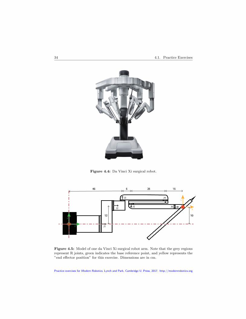
Practice exercise 4.3 Figure 4.4 shows a da Vinci Xi, used in several typesof robot-assisted surgery. Though it is mechanically constrained to have only 3degrees of freedom per arm, for the sake of this exercise assume each arm is asimple serial chain with 6 degrees of freedom.
(a) Write the M matrix for the arm if its home configuration is shown inFigure 4.5.
Practice exercises for Modern Robotics, Lynch and Park, Cambridge U. Press, 2017. http://modernrobotics.org

Chapter 4. Practice Exercises on Forward Kinematics 33
x
y
z
x
J1
J2
J3
J4
J6
J5
J7
Figure 4.3: A top view of the Sawyer robot arm at its home configuration. Dimen-sions are in mm. Assume that the centerlines shown are the screw axes of the revolutejoints. The s frame is at the base of the arm. The height from the base to the firstjoint is 317 mm.
(b) Find the space frame screw axes for this system.(c) Determine the position of the end effector if the joints are at (0,π4 ,π4 , 3π4 ,π2 ).
Again, the MR Library will prove useful here.
Practice exercises for Modern Robotics, Lynch and Park, Cambridge U. Press, 2017. http://modernrobotics.org
34 4.1. Practice Exercises
Figure 4.4: Da Vinci Xi surgical robot.
45 5 25 15
1012
J3
J1
J2 J5
J4
J6
z
x
z
x
Figure 4.5: Model of one da Vinci Xi surgical robot arm. Note that the grey regionsrepresent R joints, green indicates the base reference point, and yellow represents the”end effector position” for this exercise. Dimensions are in cm.
Practice exercises for Modern Robotics, Lynch and Park, Cambridge U. Press, 2017. http://modernrobotics.org

Chapter 4. Practice Exercises on Forward Kinematics 35
4.2 Solutions
Solution 4.1
M =
1 0 0 00 1 0 00 0 1 L1 + L2 + L3 + L4
0 0 0 1
.
Lining up the screw axes as columns, we get
Slist =
0 1 0 1 0 1 00 0 0 0 0 0 01 0 1 0 1 0 10 0 0 0 0 0 00 L1 0 L1 + L2 0 L1 + L2 + L3 00 0 0 0 0 0 0
and
Blist =
0 1 0 1 0 1 00 0 0 0 0 0 01 0 1 0 1 0 10 0 0 0 0 0 00 −(L2 + L3 + L4) 0 −(L3 + L4) 0 −L4 00 0 0 0 0 0 0
.
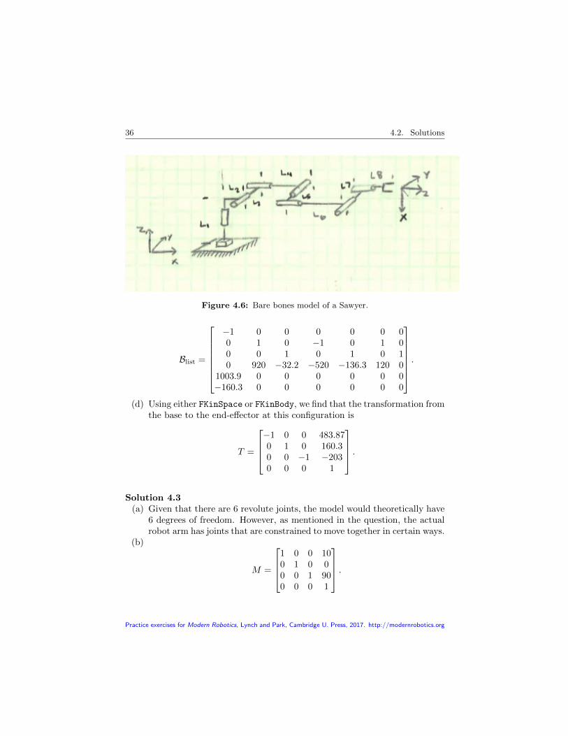
Solution 4.2(a) See Figure 4.6.(b)
M =
0 0 1 1003.90 1 0 160.3−1 0 0 317.00 0 0 1
.
(c)
Slist =
0 0 1 0 1 0 10 1 0 −1 0 1 01 0 0 0 0 0 00 −317 0 317 0 −317 00 0 317 0 317 0 3170 83.87 −192.5 −483.87 −24 883.87 −160.3
Practice exercises for Modern Robotics, Lynch and Park, Cambridge U. Press, 2017. http://modernrobotics.org
36 4.2. Solutions
Figure 4.6: Bare bones model of a Sawyer.
Blist =
−1 0 0 0 0 0 00 1 0 −1 0 1 00 0 1 0 1 0 10 920 −32.2 −520 −136.3 120 0
1003.9 0 0 0 0 0 0−160.3 0 0 0 0 0 0
.
(d) Using either FKinSpace or FKinBody, we find that the transformation fromthe base to the end-effector at this configuration is
T =
−1 0 0 483.870 1 0 160.30 0 −1 −2030 0 0 1
.
Solution 4.3(a) Given that there are 6 revolute joints, the model would theoretically have
6 degrees of freedom. However, as mentioned in the question, the actualrobot arm has joints that are constrained to move together in certain ways.
(b)
M =
1 0 0 100 1 0 00 0 1 900 0 0 1
.
Practice exercises for Modern Robotics, Lynch and Park, Cambridge U. Press, 2017. http://modernrobotics.org

Chapter 4. Practice Exercises on Forward Kinematics 37
(c) First, we need to derive the screw axes for each of the revolute joints. Thespace-frame axis list is:
Slist =
0 0 1 1 00 0 0 0 01 1 0 0 10 0 0 0 00 −12 75 −50 −100 0 0 0 0
This, along with the M matrix and provided joint angles, can be fedinto FKinSpace, which returns that the transformation matrix to the end-effector in this case is
T =
.7071 −.7071 0 −51.91−.7071 −.7071 0 61.09
0 0 −1 −153.390 0 0 1
.
Practice exercises for Modern Robotics, Lynch and Park, Cambridge U. Press, 2017. http://modernrobotics.org
38 4.2. Solutions
Practice exercises for Modern Robotics, Lynch and Park, Cambridge U. Press, 2017. http://modernrobotics.org

Chapter 5
Practice Exercises onVelocity Kinematics andStatics
5.1 Practice Exercises
Practice exercise 5.1 Figure 4.1 shows the KUKA LBR iiwa 7R robot arm.The figure defines an {s} frame at the base with the ys-axis pointing out of thepage and a {b} frame aligned with {s} at the end-effector. The robot is at itshome configuration. The screw axes for the seven joints are illustrated (positiverotation about these axes is by the right-hand rule). The axes for joints 2, 4,and 6 are aligned, and the axes for joints 1, 3, 5, and 7 are identical at the homeconfiguration. The dimensions are L1 = 0.34 m, L2 = 0.4 m, L3 = 0.4 m, andL4 = 0.15 m.
(a) What is the space Jacobian when the robot is at its home configuration?(b) What is the body Jacobian when the robot is at its home configuration?(c) What is the rank of the space and body Jacobian at the home configu-
ration? (It is always the same.) Is the home configuration a singularity?What is the dimension of the space of feasible twists at the home config-uration?
For the remaining questions, assume the angles of the joints are iπ/16 for jointsi = 1 . . . 7.
(d) What is the space Jacobian? What joint torques are needed to generate
39

40 5.1. Practice Exercises
the wrench Fs = (1 Nm, 1 Nm, 1 Nm, 1 N, 1 N, 1 N)? What is the ma-nipulability measure µ2 for the angular velocity manipulability ellipsoidin the space frame? What is the manipulability measure µ2 for the linearmanipulability ellipsoid in the space frame?
(e) What is the body Jacobian? What joint torques are needed to generatethe wrench Fb = (1 Nm, 1 Nm, 1 Nm, 1 N, 1 N, 1 N)? What is the ma-nipulability measure µ2 for the angular velocity manipulability ellipsoidin the body frame? What is the manipulability measure µ2 for the linearmanipulability ellipsoid in the body frame?
Practice exercise 5.2 Consider a robot with eight joints moving in space.The configuration of the end-effector is represented as an element of SE(3), thevelocity of the end-effector is represented as a twist V ∈ R6, and the force andmoment at the end-effector is represented as a wrench F ∈ R6. At some jointconfigurations of the robot, the Jacobian has rank 6; at other configurations,the rank of the Jacobian is lower. Consider a particular joint configuration θwhere the rank of the Jacobian is k.
(a) In the 8-dimensional space of joint velocities θ, what is the dimension ofthe subspace of joint velocities that produce zero twist (V = 0, no motion)of the end-effector?
(b) In the 6-dimensional space of wrenches F applied to the end-effector, whatis the dimension of the subspace of wrenches that the robot can resist witha zero joint force-torque vector, τ = 0?
In the remaining questions, assume that 1 < k < 6.(c) Assume the task is to position the end-effector in SE(3). Is the robot
redundant, kinematically deficient, or neither with respect to this task?(d) Is the longest axis of the manipulability ellipsoid zero, infinite, or other?(e) Is the shortest axis of the manipulability ellipsoid zero, infinite, or other?(f) Is the longest axis of the force ellipsoid zero, infinite, or other?(g) Is the shortest axis of the force ellipsoid zero, infinite, or other?
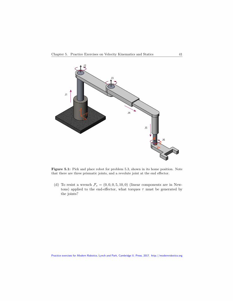
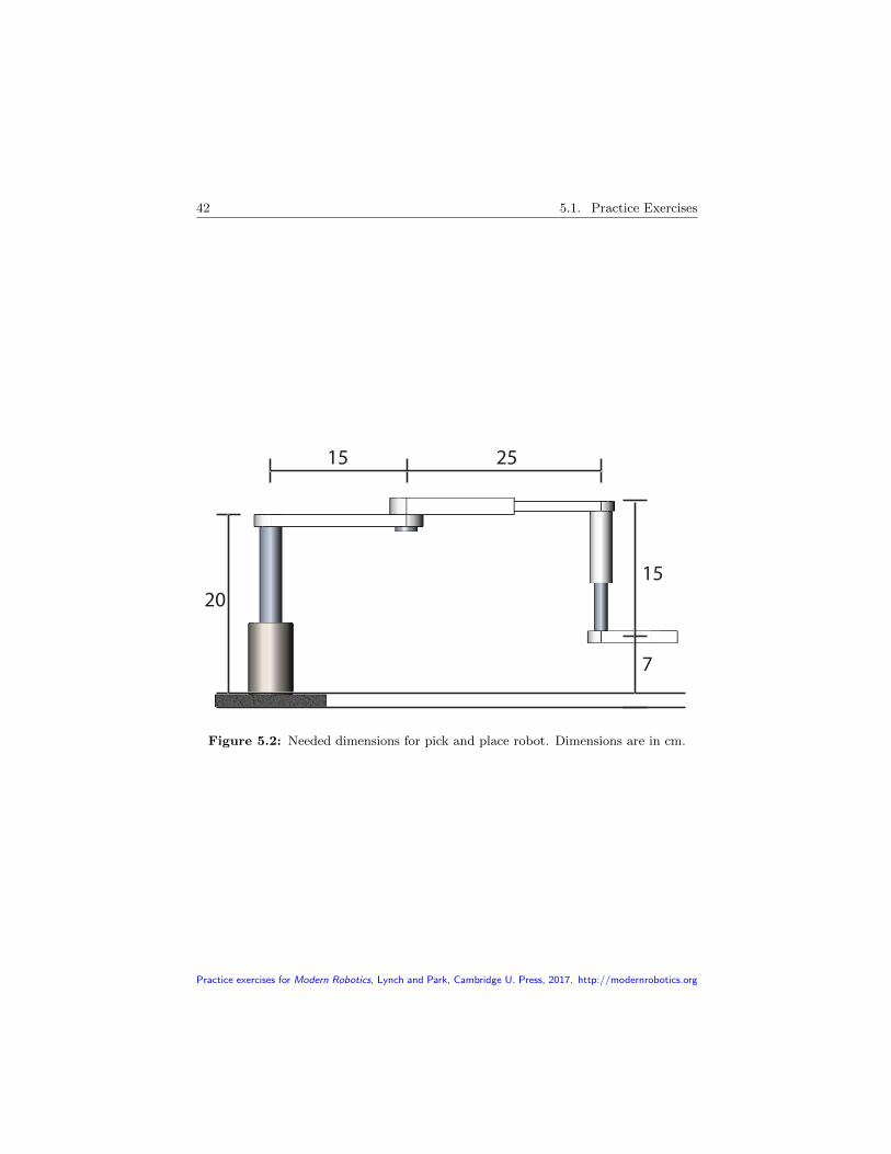
Practice exercise 5.3 Figure 5.1 shows a simplified pick-and-place roboticarm. Let’s apply velocity kinematics and statics to this system. Assume thatthe robot is shown in its home position, and that dimensions shown in Figure5.2 are for this configuration.
(a) Find the space-frame screw axis for each joint when the robot is at itshome configuration.
(b) Use the MR library to find Js(θ) at θ = (10, π/4,−π/4, 2, 2, 0).(c) Calculate the body Jacobian beginning with the space Jacobian at the
home configuration.
Practice exercises for Modern Robotics, Lynch and Park, Cambridge U. Press, 2017. http://modernrobotics.org
Chapter 5. Practice Exercises on Velocity Kinematics and Statics 41
J1
J2
J3
J4
J5
J6
x
y
z
Figure 5.1: Pick and place robot for problem 5.3, shown in its home position. Notethat there are three prismatic joints, and a revolute joint at the end effector.
(d) To resist a wrench Fs = (0, 0, 0, 5, 10, 0) (linear components are in New-tons) applied to the end-effector, what torques τ must be generated bythe joints?
Practice exercises for Modern Robotics, Lynch and Park, Cambridge U. Press, 2017. http://modernrobotics.org
42 5.1. Practice Exercises
20
15 25
15
7
Figure 5.2: Needed dimensions for pick and place robot. Dimensions are in cm.
Practice exercises for Modern Robotics, Lynch and Park, Cambridge U. Press, 2017. http://modernrobotics.org
Chapter 5. Practice Exercises on Velocity Kinematics and Statics 43
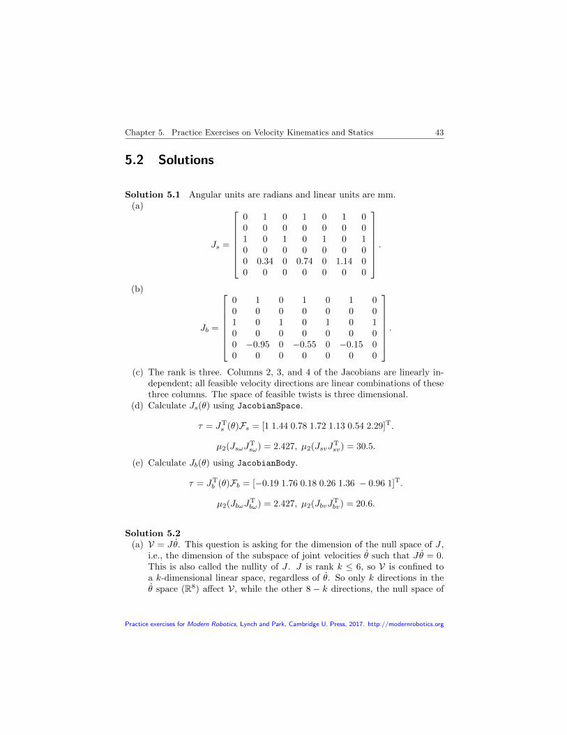
5.2 Solutions
Solution 5.1 Angular units are radians and linear units are mm.(a)
Js =
0 1 0 1 0 1 00 0 0 0 0 0 01 0 1 0 1 0 10 0 0 0 0 0 00 0.34 0 0.74 0 1.14 00 0 0 0 0 0 0
.
(b)
Jb =
0 1 0 1 0 1 00 0 0 0 0 0 01 0 1 0 1 0 10 0 0 0 0 0 00 −0.95 0 −0.55 0 −0.15 00 0 0 0 0 0 0
.
(c) The rank is three. Columns 2, 3, and 4 of the Jacobians are linearly in-dependent; all feasible velocity directions are linear combinations of thesethree columns. The space of feasible twists is three dimensional.
(d) Calculate Js(θ) using JacobianSpace.
τ = JTs (θ)Fs = [1 1.44 0.78 1.72 1.13 0.54 2.29]T.
µ2(JsωJTsω) = 2.427, µ2(JsvJ
Tsv) = 30.5.
(e) Calculate Jb(θ) using JacobianBody.
τ = JTb (θ)Fb = [−0.19 1.76 0.18 0.26 1.36 − 0.96 1]T.
µ2(JbωJTbω) = 2.427, µ2(JbvJ
Tbv) = 20.6.
Solution 5.2(a) V = Jθ. This question is asking for the dimension of the null space of J ,
i.e., the dimension of the subspace of joint velocities θ such that Jθ = 0.This is also called the nullity of J . J is rank k ≤ 6, so V is confined toa k-dimensional linear space, regardless of θ. So only k directions in theθ space (R8) affect V, while the other 8 − k directions, the null space of
Practice exercises for Modern Robotics, Lynch and Park, Cambridge U. Press, 2017. http://modernrobotics.org
44 5.2. Solutions
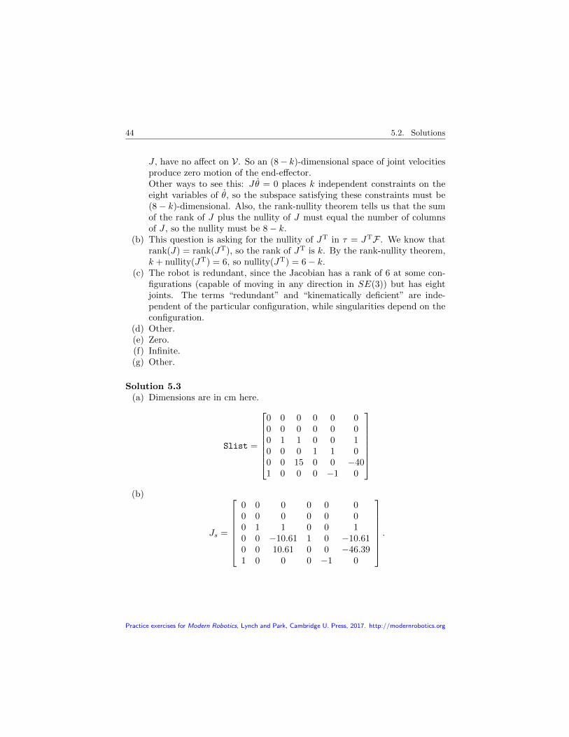
J , have no affect on V. So an (8− k)-dimensional space of joint velocitiesproduce zero motion of the end-effector.Other ways to see this: Jθ = 0 places k independent constraints on theeight variables of θ, so the subspace satisfying these constraints must be(8− k)-dimensional. Also, the rank-nullity theorem tells us that the sumof the rank of J plus the nullity of J must equal the number of columnsof J , so the nullity must be 8− k.
(b) This question is asking for the nullity of JT in τ = JTF . We know thatrank(J) = rank(JT), so the rank of JT is k. By the rank-nullity theorem,k + nullity(JT) = 6, so nullity(JT) = 6− k.
(c) The robot is redundant, since the Jacobian has a rank of 6 at some con-figurations (capable of moving in any direction in SE(3)) but has eightjoints. The terms “redundant” and “kinematically deficient” are inde-pendent of the particular configuration, while singularities depend on theconfiguration.
(d) Other.(e) Zero.(f) Infinite.(g) Other.
Solution 5.3(a) Dimensions are in cm here.
Slist =
0 0 0 0 0 00 0 0 0 0 00 1 1 0 0 10 0 0 1 1 00 0 15 0 0 −401 0 0 0 −1 0
(b)
Js =
0 0 0 0 0 00 0 0 0 0 00 1 1 0 0 10 0 −10.61 1 0 −10.610 0 10.61 0 0 −46.391 0 0 0 −1 0
.
Practice exercises for Modern Robotics, Lynch and Park, Cambridge U. Press, 2017. http://modernrobotics.org

Chapter 5. Practice Exercises on Velocity Kinematics and Statics 45
(c)
Jb =
0 0 0 0 0 00 0 0 0 0 00 1 1 0 0 10 0 0 1 0 00 40 −55 0 0 01 0 0 0 −1 0
.
(d) Keep in mind that torque is measured in Nm, so make sure to convert theresults to the right scale, given that all measurements are in cm.
τ =
00
.5303−.05
03.231
.
Practice exercises for Modern Robotics, Lynch and Park, Cambridge U. Press, 2017. http://modernrobotics.org

46 5.2. Solutions
Practice exercises for Modern Robotics, Lynch and Park, Cambridge U. Press, 2017. http://modernrobotics.org
Chapter 6
Practice Exercises onInverse Kinematics
6.1 Practice Exercises
Practice exercise 6.1 The spatial RRP open chain of Figure 6.1 is shown inits zero position.
(a) Use analytic methods to solve the inverse kinematics when the end-effectorconfiguration is described by
T =
0 1 0 2L0 0 −1 0−1 0 0 −3L0 0 0 1
.
(b) Assume that L = 1 and use a numerical method (e.g., from the MR codelibrary) to solve the same problem as in (a).
Practice exercise 6.2 Figure 6.2(a) shows the world’s first robot system thatlearns to dress elderly and physically disabled people. The system consists of two7R WAM robots, whose kinematics are given in Chapter 4.1.3 of the textbook.The overview of the system is shown in Figure 6.2(b). The WAM robots aremounted symmetrically. Suppose the world frame is set as shown in the figureand Dx = Dz = 0.3 m. The task is to move one of the robot end-effector frames
47

48 6.1. Practice Exercises
{s}
θ1
θ2
θ3
L
L
L
L{e}
xe ye
ze
xsys
zs
Figure 6.1: An RRP robot.
to the configuration
T =
0 0 1 0.150 −1 0 01 0 0 0.30 0 0 1
,
relative to {w}, to hold the clothes. Use the MR code library to solve thefollowing questions. (Ignore joint limits.)
(a) If one of the robot arms can achieve the configuration, would you generallyexpect there to be one solution to the inverse kinematics, a finite numberof solutions, or an infinite number of solutions?
(b) Can the left arm achieve the configuration? You could use numericalinverse kinematics with different initial guesses, if needed. If you find asolution, use forward kinematics to verify it. If you cannot find a solution,explain the reason.
(c) Can the right arm achieve the configuration? You could use numericalinverse kinematics with different initial guesses, if needed. If you find asolution, use forward kinematics to verify it. If you cannot find a solution,explain the reason.
Practice exercises for Modern Robotics, Lynch and Park, Cambridge U. Press, 2017. http://modernrobotics.org
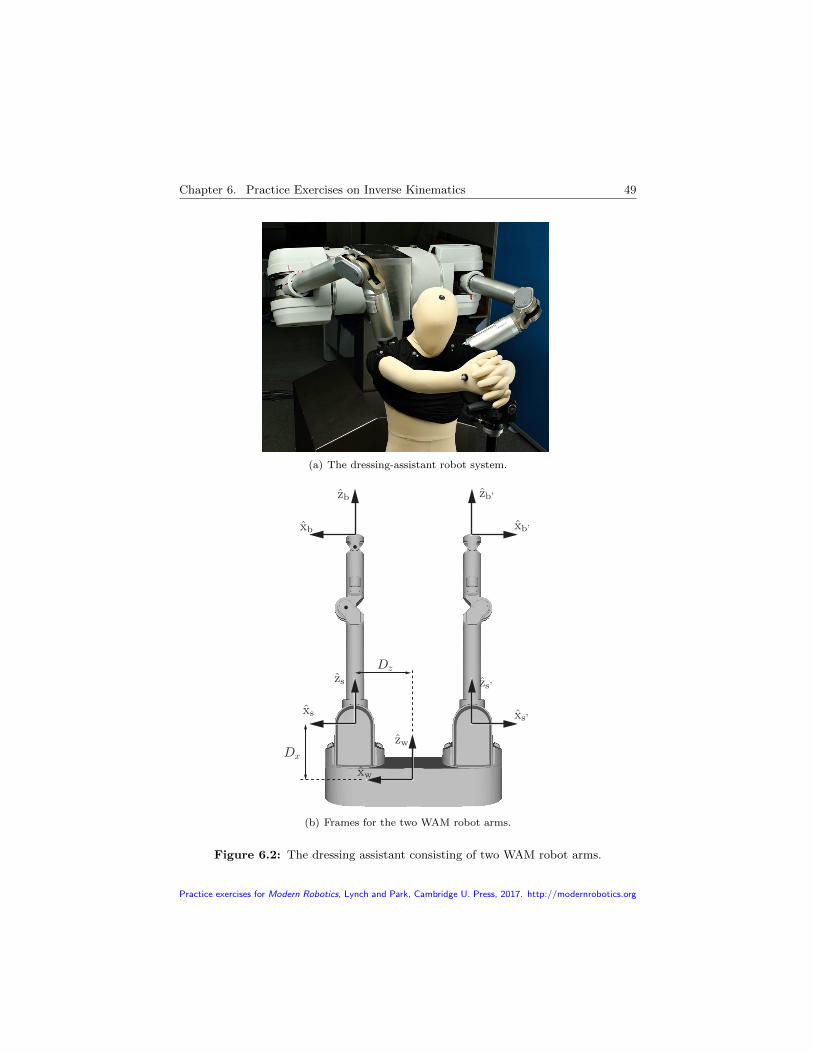
Chapter 6. Practice Exercises on Inverse Kinematics 49
(a) The dressing-assistant robot system.
xb
zb
xs
zs
xw
zw
zb’
xb’
zs’
xs’
D
D
x
z
(b) Frames for the two WAM robot arms.
Figure 6.2: The dressing assistant consisting of two WAM robot arms.
Practice exercises for Modern Robotics, Lynch and Park, Cambridge U. Press, 2017. http://modernrobotics.org

50 6.2. Solutions
6.2 Solutions
Solution 6.1(a) By inspection the first joint rotates along its axis parallel to zs-axis, while
the rotation axis of the second joint can move in a plane parallel to xs− ys
plane. The orientation of the end-effector can be achieved from the initialorientation by first rotating about the zs-axis for −π/2 rad and then ro-tating about the xs-axis for π/2 rad. So we know that to reach the finalend-effetor configuration, θ1 = −π/2 and θ2 = π/2. By checking the trans-lation we find θ3 = L. So the joint angles should be θ = (−π/2, π/2, L).
(b) Use the MR code library (e.g., IKinBody), to find the same result, begin-ning from an initial guess away from the solution.
Solution 6.2(a) You would expect an infinite number of solutions, since the robot is re-
dundant (it has 7 dof).(b) The configuration is outside the left robot’s workspace, so there is no
solution.(c) Considering the inverse kinematics in the body frame of the right arm,
you would get
Jb =
0 0 0 0 0 0 00 1 0 1 0 1 01 0 1 0 1 0 10 0.91 0 0.36 0 0.06 00 0 0 0 0 0 00 0 0 0.045 0 0 0
and
M =
−1 0 0 −0.30 −1 0 00 0 1 1.210 0 0 1
.
One example solution, found using IKinBody, is
θ = (0,−2.2130, 0, 2.6198, 0,−1.9776, 0).
Practice exercises for Modern Robotics, Lynch and Park, Cambridge U. Press, 2017. http://modernrobotics.org

Chapter 7
Practice Exercises onKinematics of ClosedChains
There are currently no chapter 7 practice exercises.
51

52
Practice exercises for Modern Robotics, Lynch and Park, Cambridge U. Press, 2017. http://modernrobotics.org
Chapter 8
Practice Exercises onDynamics of Open Chains
8.1 Practice Exercises
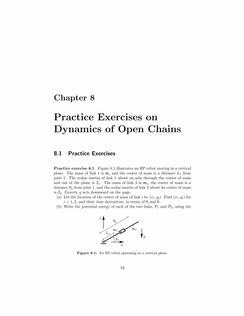
Practice exercise 8.1 Figure 8.1 illustrates an RP robot moving in a verticalplane. The mass of link 1 is m1 and the center of mass is a distance L1 fromjoint 1. The scalar inertia of link 1 about an axis through the center of massand out of the plane is I1. The mass of link 2 is m2, the center of mass is adistance θ2 from joint 1, and the scalar inertia of link 2 about its center of massis I2. Gravity g acts downward on the page.
(a) Let the location of the center of mass of link i be (xi, yi). Find (xi, yi) fori = 1, 2, and their time derivatives, in terms of θ and θ.
(b) Write the potential energy of each of the two links, P1 and P2, using the
x
y
θ1
θ2
L1g
m1m2
Figure 8.1: An RP robot operating in a vertical plane.
53

54 8.1. Practice Exercises
joint variables θ.(c) Write the kinetic energy of each of the two links, K1 and K2. (Recall that
the kinetic energy of a rigid body moving in the plane is K = (1/2)mv2 +(1/2)Iω2, where m is the mass, v is the scalar linear velocity at the centerof mass, ω is the scalar angular velocity, and I is the scalar inertia of therigid body about its center of mass.)
(d) What is the Lagrangian in terms of K1, K2, P1, and P2?(e) One of the terms in the Lagrangian can be expressed as
1
2m2θ
22 θ
21.
If this were the complete Lagrangian, what would the equations of motionbe? Derive these by hand (no symbolic math software assistance). Indicatewhich of the terms in your equations are a function of θ, which are Coriolisterms, which are centripetal terms, and which are gravity terms, if any.
(f) Now derive the equations of motion (either by hand or using symbolicmath software for assistance) for the full Lagrangian and put them in theform
τ = M(θ)θ + c(θ, θ) + g(θ).
Identify which of the terms in c(θ, θ) are Coriolis and which are centripetal.Explain as if to someone who is unfamiliar with dynamics why these termscontribute to the joint forces and torques.
(g) Consider the configuration-dependent mass matrix M(θ) from your pre-vious answer. When the robot is at rest (and ignoring gravity), the massmatrix can be visualized as the ellipse of joint forces/torques that are re-quired to generate the unit circle of joint accelerations in θ space. As θ2increases, how does this ellipse change? Describe it in text and provide adrawing.
(h) Now visualize the configuration-dependent end-effector mass matrix Λ(θ),where the “end-effector” is considered to be at the point (x2, y2), thelocation of the center of mass of the second link. For a unit circle ofaccelerations (x2, y2), consider the ellipse of linear forces that are requiredto be applied at the end-effector to realize these accelerations. How doesthe orientation of this ellipse change as θ1 changes? How does the shapechange as θ2 increases from zero to infinity when θ1 = 0? Provide adrawing for the case θ1 = 0. If you have access to symbolic computationsoftware (e.g., Mathematica), you can use the Jacobian J(θ) satisfying
[x2y2
]= J(θ)θ
Practice exercises for Modern Robotics, Lynch and Park, Cambridge U. Press, 2017. http://modernrobotics.org

Chapter 8. Practice Exercises on Dynamics of Open Chains 55
x
y
θ1
θ2
L1
L2
m1
m2
Figure 8.2: A 2R robot with all mass concentrated at the ends of the links.
to calculate Λ(θ) = J−T(θ)M(θ)J−1(θ) for the case θ1 = 0. If you do nothave access to symbolic computation software, you can plug in numericalvalues for I1, I2, m1, m2, and L1 (make them all equal to 1, for example)to say something about how Λ changes (and therefore how the ellipsechanges) as θ2 goes from zero to infinity while θ1 = 0.
Practice exercise 8.2 The mass matrix of the 2R robot of Figure 8.2 is
M(θ) =
[m1L
21 + m2(L2
1 + 2L1L2 cos θ2 + L22) m2(L1L2 cos θ2 + L2
2)m2(L1L2 cos θ2 + L2
2) m2L22
],
where each link is modeled as a point mass at the end of the link. Explain intext and/or figures why each of the entries makes sense, for example using thejoint accelerations θ = (1, 0) and (0, 1).
Practice exercise 8.3 The equations of motion for a particular 2R robot armcan be written M(θ)θ+ c(θ, θ)+g(θ) = τ . The Lagrangian L(θ, θ) for the robotcan be written in components as
L(θ, θ) = L1(θ, θ) + L2(θ, θ) + L3(θ, θ) + . . .
One of these components is L1 = mθ1θ2 cos θ2.(a) Find the joint torques τ1 and τ2 corresponding to the component L1.(b) Write the 2 × 2 mass matrix M1(θ), the velocity-product vector c1(θ, θ),
and the gravity vector g1(θ) corresponding to L1. (Note that M = M1 +M2 +M3 + . . ., c = c1 + c2 + c3 + . . ., and g = g1 + g2 + g3 + . . .)
Practice exercise 8.4 For a given configuration θ of a two-joint robot, themass matrix is
M(θ) =
[3 ab 2
],
Practice exercises for Modern Robotics, Lynch and Park, Cambridge U. Press, 2017. http://modernrobotics.org

56 8.1. Practice Exercises
which has a determinant of 6 − ab and eigenvalues 12 (5 ±
√1 + 4ab). What
constraints must a and b satisfy for this to be a valid mass matrix?
Practice exercise 8.5 Link i of an open-chain robot has two frames attachedto it, a frame {b} at its center of mass and a frame {a} on the axis of jointi, a revolute joint, that drives the link. In the frame {a}, the screw axis ofthe revolute joint is expressed as S. In the backward iterations of Newton-Eulerinverse dynamics, it was determined that the wrench Fb (expressed in {b}) mustbe applied to the link. What joint torque τi must be applied at joint i, in termsof Fb, S, and the frames {a} and {b}?
Practice exercise 8.6 Consider the four equivalent forms of dynamics shownbelow:
τ = M(θ)θ + h(θ, θ) + JT(θ)Ftip, (8.1)
τ = M(θ)θ + c(θ, θ) + g(θ) + JT(θ)Ftip, (8.2)
τ = M(θ)θ + C(θ, θ)θ + g(θ) + JT(θ)Ftip, (8.3)
τ = M(θ)θ + θTΓ(θ)θ + g(θ) + JT(θ)Ftip, (8.4)
(a) List the variables common to all of the equations, what they represent,their dimension, how they are derived, and any constraints they mustalways follow or properties they must satisfy.
(b) For the uniqe variables in each of the equations, describe what they rep-resent and provide the dimension.
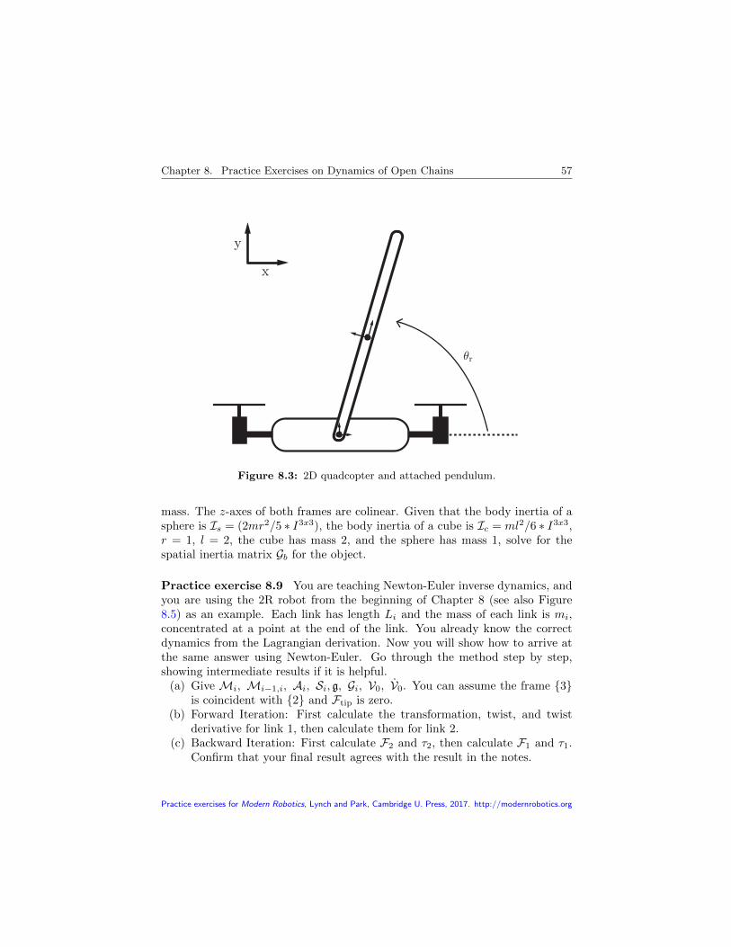
Practice exercise 8.7 Consider the quadcopter and attached pendulum shownin Figure 8.3. The rod is attached to the quadcopter by a revolute joint, and youare given the task of balancing the rod upright (a flying version of the classiccart pendulum problem). Assume the configuration of the quadcopter center isdescribed by (xq, yq, θq) and the configuration of the rod center is described as(xr, yr, θr) where θq and θr are measured with respect to the world x axis. Thelength of the rod is 2l, the masses are mq, and mr, and the rotational inertiasare Iq and Ir.
Solve for the kinetic and potential energy terms and the Lagrangian for thegeneralized coordinates (xq, yq, θq, θr).
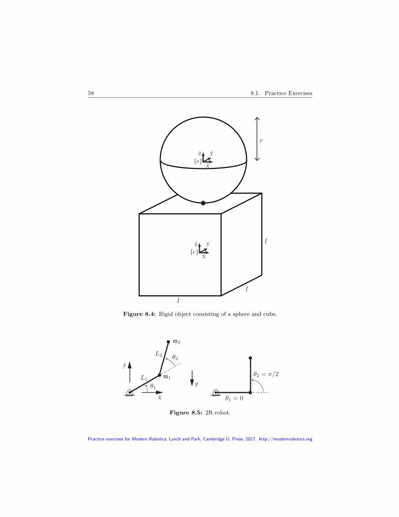
Practice exercise 8.8 Consider the object in Figure 8.4 that consists of acube and sphere that are rigidly attached. The {c} and {s} frames of eachcomponent are aligned with the principal axes and located at the center of
Practice exercises for Modern Robotics, Lynch and Park, Cambridge U. Press, 2017. http://modernrobotics.org
Chapter 8. Practice Exercises on Dynamics of Open Chains 57
x
y
θr
Figure 8.3: 2D quadcopter and attached pendulum.
mass. The z-axes of both frames are colinear. Given that the body inertia of asphere is Is = (2mr2/5 ∗ I3x3), the body inertia of a cube is Ic = ml2/6 ∗ I3x3,r = 1, l = 2, the cube has mass 2, and the sphere has mass 1, solve for thespatial inertia matrix Gb for the object.
Practice exercise 8.9 You are teaching Newton-Euler inverse dynamics, andyou are using the 2R robot from the beginning of Chapter 8 (see also Figure8.5) as an example. Each link has length Li and the mass of each link is mi,concentrated at a point at the end of the link. You already know the correctdynamics from the Lagrangian derivation. Now you will show how to arrive atthe same answer using Newton-Euler. Go through the method step by step,showing intermediate results if it is helpful.
(a) Give Mi, Mi−1,i, Ai, Si, g, Gi, V0, V0. You can assume the frame {3}is coincident with {2} and Ftip is zero.
(b) Forward Iteration: First calculate the transformation, twist, and twistderivative for link 1, then calculate them for link 2.
(c) Backward Iteration: First calculate F2 and τ2, then calculate F1 and τ1.Confirm that your final result agrees with the result in the notes.
Practice exercises for Modern Robotics, Lynch and Park, Cambridge U. Press, 2017. http://modernrobotics.org
58 8.1. Practice Exercises
l
l
l
r
{s}x
yz
{c}x
yz
Figure 8.4: Rigid object consisting of a sphere and cube.
x
y
θ1
θ2
L1
L2
g
θ1 = 0
θ2 = π/2m1
m2
Figure 8.5: 2R robot.
Practice exercises for Modern Robotics, Lynch and Park, Cambridge U. Press, 2017. http://modernrobotics.org

Chapter 8. Practice Exercises on Dynamics of Open Chains 59
θ2= 1
L2
L1
θ1= 1
√L21 + 2L1L2 cos θ2 + L2
2
θ2/2
θ2
Figure 8.6: The linear accelerations of the point masses of the 2R arm for jointaccelerations (1, 0) and (0, 1).
8.2 Solutions
Solution 8.1 Coming soon.
Solution 8.2 Let
M =
[M11 M12
M21 M22
],
where M11 = m1L21+m2(L2
1+2L1L2 cos θ2+L22), M12 = M21 = m2(L1L2 cos θ2+
L22), and M22 = m2L
22.
Figure 8.6 shows the linear accelerations of the masses m1 and m2 for jointaccelerations (1, 0) and (0, 1).
The terms M11 and M22 are relatively easy to understand. The termM11 is the inertia of the robot about joint 1 if joint 2 is locked. The in-ertia contribution due to m1 is m1L
21. The distance of m2 from joint 1 is
d2 =√L21 + 2L1L2 cos θ2 + L2
2 (by the law of cosines), and the inertia con-tribution due to m2 is m2d
22.
The term M22 is the inertia about joint 2 due to the mass m2 a distance L2
from the joint.The off-diagonal term is harder to understand. But we know that if joint
1 accelerates, joint 2 has to apply a torque to keep joint 2 locked. And ifjoint 2 accelerates, joint 1 has to apply a torque to remain locked; otherwise,conservation of angular momentum about joint 1 would cause it to begin torotate in a direction opposite joint 2. Using Figure 8.6 and some geometry,
Practice exercises for Modern Robotics, Lynch and Park, Cambridge U. Press, 2017. http://modernrobotics.org

60 8.2. Solutions
you could calculate the joint torque τ2 required to keep joint 2 stationary whenθ1 = 1, based on the moment about joint 2 generated by the line of force requiredto accelerate m2.
Solution 8.3(a)
τ1 =d
dt
(∂L1
∂θ1
)− ∂L1
∂θ1=
d
dt(mθ2 cos θ2)− 0 = mθ2 cos θ2 −mθ22 sin θ2
τ2 =d
dt
(∂L1
∂θ2
)− ∂L1
∂θ2=
d
dt(mθ1 cos θ2) + mθ1θ2 sin θ2 = mθ1 cos θ2
(b)
M1(θ) =
[0 m cos θ2
m cos θ2 0
], c1(θ, θ) =
[−mθ22 sin θ2
0
],
g1(θ) =
[00
].
Solution 8.4 M(θ) must be positive definite (and therefore symmetric), soa = b and the eigenvalues must be positive, so |a| = |b| <
√6. (The determinant
det(M) = 6− a2 must be positive, which gives the same condition on |a|.)
Solution 8.5 Take the dot product of the wrench with the screw axis afterthey’ve been expressed in the same frame, e.g., in the frame {b}, FT
b [AdTba]S.
Solution 8.6(a) τ : the torque or force at each of the joints represented by the generalized
coordinates. Dimensions are n× 1 array.M(θ): the configuration dependent mass matrix. Dimensions are n × nmatrix. M must be symmetric and positive definite.θ: The generalized coordinates for the joints. Dimensions are n× 1 array.θ: The acceleration of the joints represented by the generalized coordi-nates. Dimensions are n× 1 array.J(θ): The Jacobian (depends on configuration θ). Dimensions are n × nmatrix.Ftip: The force applied at the tip of the robot. Dimensions are n×1 array.
(b) 8.1: The most general representation, and h(θ, θ) is an n × 1 array thatcontains the centripetal, coriolis, and gravity terms.
Practice exercises for Modern Robotics, Lynch and Park, Cambridge U. Press, 2017. http://modernrobotics.org

Chapter 8. Practice Exercises on Dynamics of Open Chains 61
8.2: c(θ, θ) is an n × 1 array that contains the centripetal and coriolisterms, and g(θ) is an n× 1 array that contains the gravity terms.8.3: C(θ, θ) is the n× n Coriolis matrix.8.4: Γ(θ) is the n×n×n Christoffel matrix. Emphasizes that the Coriolisand centripetal (velocity product) terms are quadratic in the velocity andthat Γ depends only on θ.
Solution 8.7The kinetic energy contains the translational kinetic energy of the rod and quad-copter as well as the rotational kinetic energy of both bodies.Quadcopter translational kinetic energy:v2q = x2q + y2qKq,trans = 1
2mq(x2q + y2q ).
Quadcopter rotational kinetic energy:Kq,rot = 1
2Iq θ2q .
Rod translational kinetic energy:xr = xq + l cos(θr)yr = yq + l sin(θr)
xr = xq − l sin(θr)θryr = yq + l cos(θr)θrv2r = x2r + y2r = (xq − l sin(θr)θr)
2 + (yq + l cos(θr)θr)2
Kr,trans = 12mrv
2r
Rod rotational kinetic energy:Kr,rot = 1
2Ir θ2r .
Total kinetic energy:K = Kq,trans + Kq,rot + Kr,trans + Kr,rot = 1
2mq(x2q + y2q ) + 1
2Iq θ2q + 1
2mr((xq −l sin(θr)θr)
2 + (yq + l cos(θr)θr)2) + 1
2Ir θ2r .
Potential Energy:P = 1
2mqyq + 12mr(yq + l sin(θr)).
Lagrangian = L = K − P = 12mq(x
2q + y2q ) + 1
2Iq θ2q + 1
2mr((xq − l sin(θr)θr)2 +
(yq + l cos(θr)θr)2) + 1
2Ir θ2r − 1
2mqyq + 12mr(yq + l sin(θr)).
Solution 8.8COMs = (0, 0, 3), COMc = (0, 0, 1).COMb = (COMsms + COMcmc)/2.qc = COMb − COMc
qs = COMb − COMs
I1 = Ic +mc(qTc qcI − qcqTc )
Practice exercises for Modern Robotics, Lynch and Park, Cambridge U. Press, 2017. http://modernrobotics.org
62 8.2. Solutions
I2 = Is +ms(qTs qsI − qsqTs )
Ib = I1 + I2 = diag(6.48, 6.48, 1.73)Gb = diag(6.48, 6.48, 1.73, 3, 3, 3)
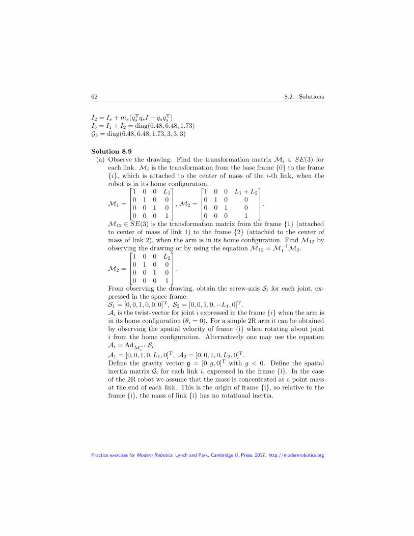
Solution 8.9(a) Observe the drawing. Find the transformation matrix Mi ∈ SE(3) for
each link. Mi is the transformation from the base frame {0} to the frame{i}, which is attached to the center of mass of the i-th link, when therobot is in its home configuration.
M1 =
1 0 0 L1
0 1 0 00 0 1 00 0 0 1
, M2 =
1 0 0 L1 + L2
0 1 0 00 0 1 00 0 0 1
.
M12 ∈ SE(3) is the transformation matrix from the frame {1} (attachedto center of mass of link 1) to the frame {2} (attached to the center ofmass of link 2), when the arm is in its home configuration. Find M12 byobserving the drawing or by using the equation M12 =M−11 M2.
M2 =
1 0 0 L2
0 1 0 00 0 1 00 0 0 1
.
From observing the drawing, obtain the screw-axis Si for each joint, ex-pressed in the space-frame:S1 = [0, 0, 1, 0, 0, 0]T, S2 = [0, 0, 1, 0,−L1, 0]T.Ai is the twist-vector for joint i expressed in the frame {i} when the arm isin its home configuration (θi = 0). For a simple 2R arm it can be obtainedby observing the spatial velocity of frame {i} when rotating about jointi from the home configuration. Alternatively one may use the equationAi = AdM−1
iSi.
A1 = [0, 0, 1, 0, L1, 0]T, A2 = [0, 0, 1, 0, L2, 0]T.Define the gravity vector g = [0, g, 0]T with g < 0. Define the spatialinertia matrix Gi for each link i, expressed in the frame {i}. In the caseof the 2R robot we assume that the mass is concentrated as a point massat the end of each link. This is the origin of frame {i}, so relative to theframe {i}, the mass of link {i} has no rotational inertia.
Practice exercises for Modern Robotics, Lynch and Park, Cambridge U. Press, 2017. http://modernrobotics.org
Chapter 8. Practice Exercises on Dynamics of Open Chains 63
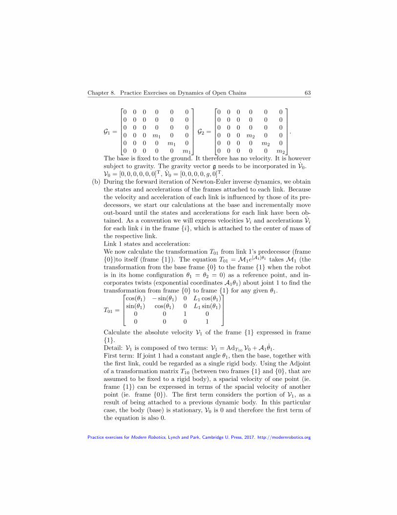
G1 =
0 0 0 0 0 00 0 0 0 0 00 0 0 0 0 00 0 0 m1 0 00 0 0 0 m1 00 0 0 0 0 m1
G2 =
0 0 0 0 0 00 0 0 0 0 00 0 0 0 0 00 0 0 m2 0 00 0 0 0 m2 00 0 0 0 0 m2
.
The base is fixed to the ground. It therefore has no velocity. It is howeversubject to gravity. The gravity vector g needs to be incorporated in V0.V0 = [0, 0, 0, 0, 0, 0]T, V0 = [0, 0, 0, 0, g, 0]T.
(b) During the forward iteration of Newton-Euler inverse dynamics, we obtainthe states and accelerations of the frames attached to each link. Becausethe velocity and acceleration of each link is influenced by those of its pre-decessors, we start our calculations at the base and incrementally moveout-board until the states and accelerations for each link have been ob-tained. As a convention we will express velocities Vi and accelerations Vifor each link i in the frame {i}, which is attached to the center of mass ofthe respective link.Link 1 states and acceleration:We now calculate the transformation T01 from link 1’s predecessor (frame{0})to itself (frame {1}). The equation T01 = M1e
[A1]θ1 takes M1 (thetransformation from the base frame {0} to the frame {1} when the robotis in its home configuration θ1 = θ2 = 0) as a reference point, and in-corporates twists (exponential coordinates A1θ1) about joint 1 to find thetransformation from frame {0} to frame {1} for any given θ1.
T01 =
cos(θ1) − sin(θ1) 0 L1 cos(θ1)sin(θ1) cos(θ1) 0 L1 sin(θ1)
0 0 1 00 0 0 1
Calculate the absolute velocity V1 of the frame {1} expressed in frame{1}.Detail: V1 is composed of two terms: V1 = AdT10 V0 +A1θ1.First term: If joint 1 had a constant angle θ1, then the base, together withthe first link, could be regarded as a single rigid body. Using the Adjointof a transformation matrix T10 (between two frames {1} and {0}, that areassumed to be fixed to a rigid body), a spacial velocity of one point (ie.frame {1}) can be expressed in terms of the spacial velocity of anotherpoint (ie. frame {0}). The first term considers the portion of V1, as aresult of being attached to a previous dynamic body. In this particularcase, the body (base) is stationary, V0 is 0 and therefore the first term ofthe equation is also 0.
Practice exercises for Modern Robotics, Lynch and Park, Cambridge U. Press, 2017. http://modernrobotics.org
64 8.2. Solutions
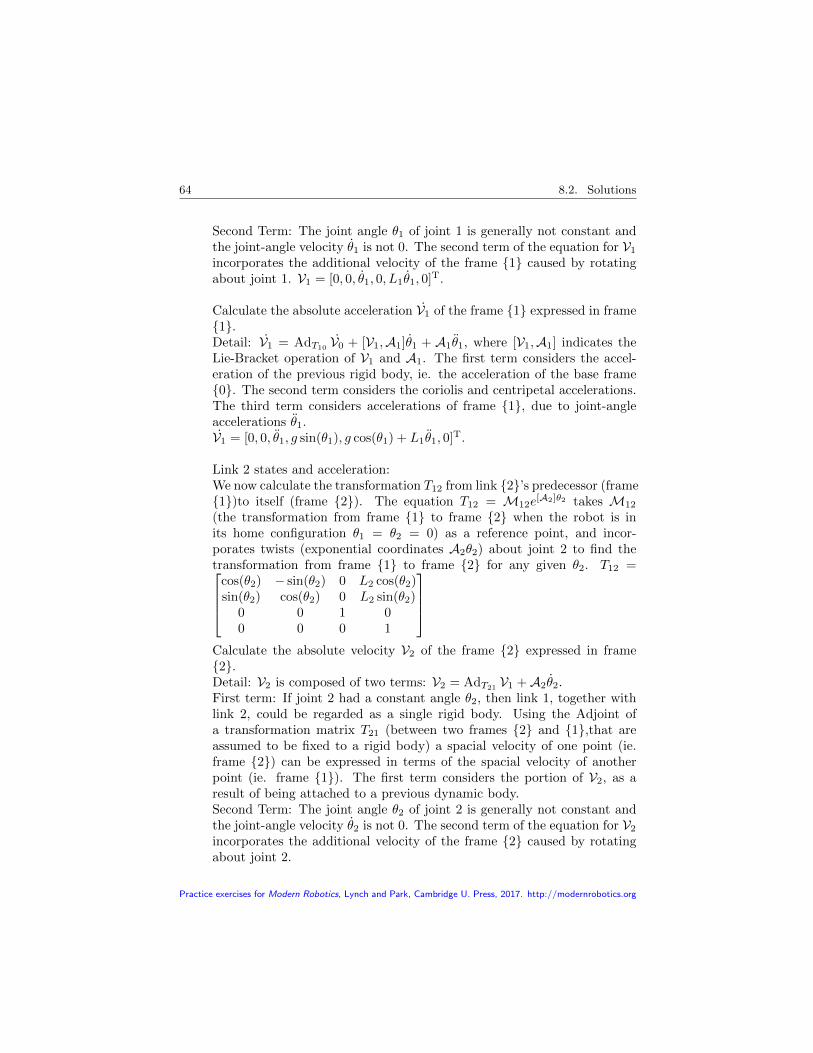
Second Term: The joint angle θ1 of joint 1 is generally not constant andthe joint-angle velocity θ1 is not 0. The second term of the equation for V1incorporates the additional velocity of the frame {1} caused by rotatingabout joint 1. V1 = [0, 0, θ1, 0, L1θ1, 0]T.
Calculate the absolute acceleration V1 of the frame {1} expressed in frame{1}.Detail: V1 = AdT10
V0 + [V1,A1]θ1 + A1θ1, where [V1,A1] indicates theLie-Bracket operation of V1 and A1. The first term considers the accel-eration of the previous rigid body, ie. the acceleration of the base frame{0}. The second term considers the coriolis and centripetal accelerations.The third term considers accelerations of frame {1}, due to joint-angleaccelerations θ1.V1 = [0, 0, θ1, g sin(θ1), g cos(θ1) + L1θ1, 0]T.
Link 2 states and acceleration:We now calculate the transformation T12 from link {2}’s predecessor (frame{1})to itself (frame {2}). The equation T12 = M12e
[A2]θ2 takes M12
(the transformation from frame {1} to frame {2} when the robot is inits home configuration θ1 = θ2 = 0) as a reference point, and incor-porates twists (exponential coordinates A2θ2) about joint 2 to find thetransformation from frame {1} to frame {2} for any given θ2. T12 =
cos(θ2) − sin(θ2) 0 L2 cos(θ2)sin(θ2) cos(θ2) 0 L2 sin(θ2)
0 0 1 00 0 0 1
Calculate the absolute velocity V2 of the frame {2} expressed in frame{2}.Detail: V2 is composed of two terms: V2 = AdT21 V1 +A2θ2.First term: If joint 2 had a constant angle θ2, then link 1, together withlink 2, could be regarded as a single rigid body. Using the Adjoint ofa transformation matrix T21 (between two frames {2} and {1},that areassumed to be fixed to a rigid body) a spacial velocity of one point (ie.frame {2}) can be expressed in terms of the spacial velocity of anotherpoint (ie. frame {1}). The first term considers the portion of V2, as aresult of being attached to a previous dynamic body.Second Term: The joint angle θ2 of joint 2 is generally not constant andthe joint-angle velocity θ2 is not 0. The second term of the equation for V2incorporates the additional velocity of the frame {2} caused by rotatingabout joint 2.
Practice exercises for Modern Robotics, Lynch and Park, Cambridge U. Press, 2017. http://modernrobotics.org

Chapter 8. Practice Exercises on Dynamics of Open Chains 65
V2 = [0, 0, θ1 + θ2, L1 sin(θ2)θ1, (L2 + L1 cos(θ2))θ1 + L2θ2, 0]T.
Calculate the absolute acceleration V2 of the frame {2} expressed in frame{2}:Detail: V2 = AdT21 V1+[V2,A2]θ2+A2θ2, where [V2,A2] indicates the Lie-Bracket operation of V2 and A2. The first term considers the accelerationof the previous rigid body, ie. the acceleration of the base frame {1}. Thesecond term considers the coriolis and centripetal accelerations. The thirdterm considers accelerations of frame {2}, due to joint-angle accelerationsθ2.V2 = [0, 0, θ1 + θ2, g sin(θ1 + θ2) +L1 cos(θ2)θ1θ2 +L1 sin(θ2)θ1, g cos(θ1 +θ2)− L1 sin(θ2)θ1θ2 + (L2 + L1 cos(θ2))θ1 + L2θ2]T.
(c) During the forward iteration, we had to bear in mind that the velocity andacceleration of link i is dependent on those of its predecessor link i − 1.Similarly, the forces acting on a link i are dependent on the forces actingon its outboard follower (i + 1): The wrench Fi that must be applied tolink i is the sum of the wrench Fi+1 that must be provided to link i + 1(but expressed in frame {i}) plus the extra wrench from the rigid bodydynamics of link i. In other words, the inboard links need to supportthe outboard links. For that reason, we run a backward iteration startingwith the most outboard link and incrementally approach the base link.Ultimately, we are solving for the torques acting on each joint, to obtainthe control torques that need to be provided to the joint motors.
Link 2 forces and torques: Find the transform from frame {2} to frame{3}. The frame n + 1 (in this case 3) is the frame attached to the end-effector. For the 2R arm we assumed that the frame {3} coincides withframe {2} (both the center of mass of link 2, as well as the end-effector arelocated at the tip of link 2). We therefore know, that T23 is the identitytransformation in SE(3),T23 = diag(1, 1, 1, 1).F3 is the wrench that the end-effector applies to the environment expressedin the frame {3}. It is given as 0.Ftip = F3 = [0, 0, 0, 0, 0, 0]T.
Calculate F2 using the equation F2 = AdT32Ftip + G2V2 − adT
V2(G2V2).Details: The first term is the wrench that must be provided by the end-effector (expressed in frame{2}). The second and third terms are thewrench that results from the dynamics of link 2.F2 = [0, 0, 0,m2(g sin(θ1+θ2)−L1 cos(θ2)θ21−L2(θ1+θ2)2+L1 sin(θ2)θ1),m2(g cos(θ1+θ2) + L1 sin(θ2)θ21 + (L2 + L1 cos(θ2)) + L2θ2), 0]T.
Practice exercises for Modern Robotics, Lynch and Park, Cambridge U. Press, 2017. http://modernrobotics.org

66 8.2. Solutions
To obtain the torque acting on joint 2, the wrench F2 is multiplied withthe twist-vector for joint 2 expressed in the frame 2, namely A2,τ2 = L2m2(θ2L2 + θ1(L2 + L1 cos(θ2)) + g cos(θ1 + θ2) + θ21L1 sin(θ2)).Link 1 forces and torques are obtained analogous to link 2: F1 = [0, 0, L2m2(L1 sin(θ2)θ21+θ2L2+θ1(L2+L1 cos(θ2))+g cos(θ1+θ2)),−L2m2 cos(θ2)(θ1+θ2)2+(m1+m2)(g sin(θ1)− θ21L1)− (θ1 + θ2)L2m2 sin(θ2),−L2m2 sin(θ2)(θ1 + θ2)2 +(m1 +m2)(θ1L1 + g cos(θ1)) + (θ1 + θ2)L2m2 cos(θ2), 0]T.τ1 = gL1(m1+m2) cos(θ1)+θ2L2m2(L2+L1 cos(θ2))+θ1(L2
2m2+L21(m1+
m2) + 2L1L2m2 cos(θ2)) + gL2m2 cos(θ1 + θ2) − 2θ1θ2L1L2m2 sin(θ2) −θ22L1L2m2 sin(θ2)The outputs τ1 and τ2 are consistent with the results from the lagrangianapproach! We have therefore successfully demonstrated the Newton-Eulerinverse dynamics derivation for the 2R arm.
Practice exercises for Modern Robotics, Lynch and Park, Cambridge U. Press, 2017. http://modernrobotics.org
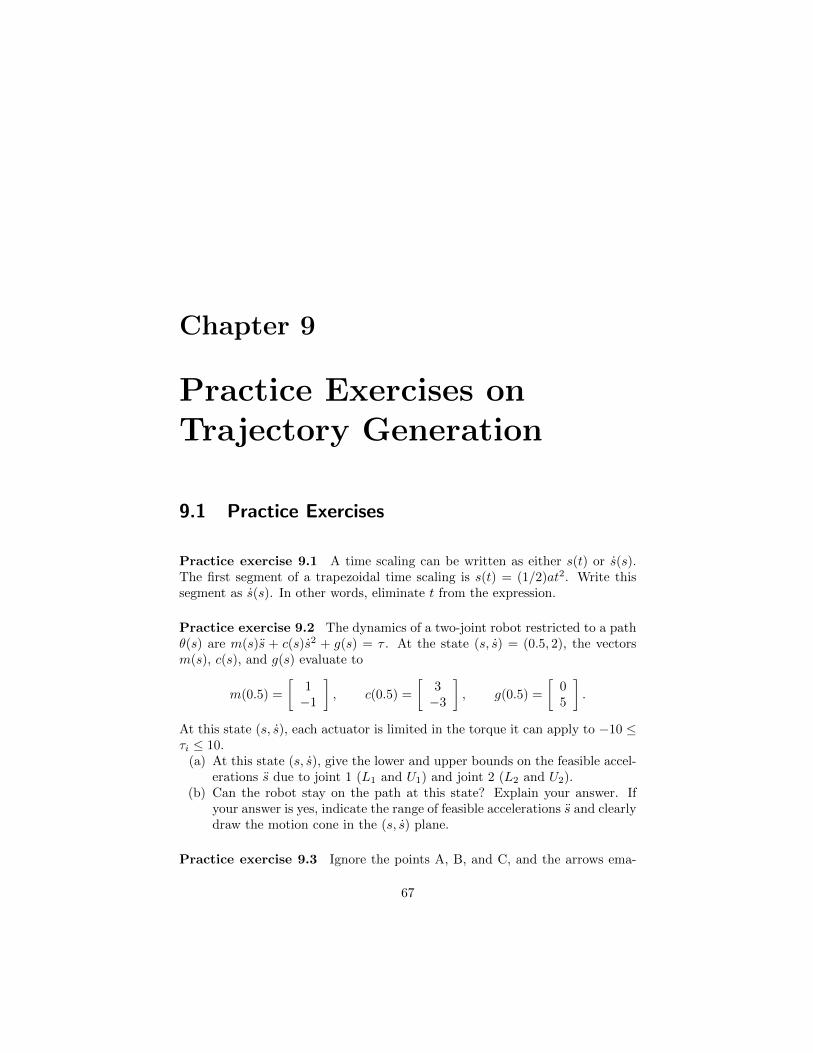
Chapter 9
Practice Exercises onTrajectory Generation
9.1 Practice Exercises
Practice exercise 9.1 A time scaling can be written as either s(t) or s(s).The first segment of a trapezoidal time scaling is s(t) = (1/2)at2. Write thissegment as s(s). In other words, eliminate t from the expression.
Practice exercise 9.2 The dynamics of a two-joint robot restricted to a pathθ(s) are m(s)s + c(s)s2 + g(s) = τ . At the state (s, s) = (0.5, 2), the vectorsm(s), c(s), and g(s) evaluate to
m(0.5) =
[1−1
], c(0.5) =
[3−3
], g(0.5) =
[05
].
At this state (s, s), each actuator is limited in the torque it can apply to −10 ≤τi ≤ 10.
(a) At this state (s, s), give the lower and upper bounds on the feasible accel-erations s due to joint 1 (L1 and U1) and joint 2 (L2 and U2).
(b) Can the robot stay on the path at this state? Explain your answer. Ifyour answer is yes, indicate the range of feasible accelerations s and clearlydraw the motion cone in the (s, s) plane.
Practice exercise 9.3 Ignore the points A, B, and C, and the arrows ema-
67
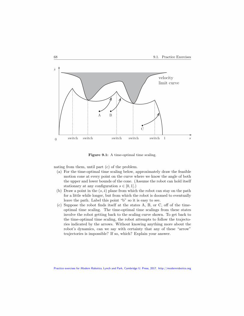
68 9.1. Practice Exercises
velocitylimit curve
s
s0 1switch switchswitch switchswitch
A B
C
Figure 9.1: A time-optimal time scaling.
nating from them, until part (c) of the problem.(a) For the time-optimal time scaling below, approximately draw the feasible
motion cone at every point on the curve where we know the angle of boththe upper and lower bounds of the cone. (Assume the robot can hold itselfstationary at any configuration s ∈ [0, 1].)
(b) Draw a point in the (s, s) plane from which the robot can stay on the pathfor a little while longer, but from which the robot is doomed to eventuallyleave the path. Label this point “b” so it is easy to see.
(c) Suppose the robot finds itself at the states A, B, or C, off of the time-optimal time scaling. The time-optimal time scalings from these statesinvolve the robot getting back to the scaling curve shown. To get back tothe time-optimal time scaling, the robot attempts to follow the trajecto-ries indicated by the arrows. Without knowing anything more about therobot’s dynamics, can we say with certainty that any of these “arrow”trajectories is impossible? If so, which? Explain your answer.
Practice exercises for Modern Robotics, Lynch and Park, Cambridge U. Press, 2017. http://modernrobotics.org
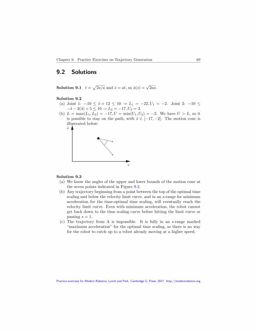
Chapter 9. Practice Exercises on Trajectory Generation 69
9.2 Solutions
Solution 9.1 t =√
2s/a and s = at, so s(s) =√
2as.
Solution 9.2(a) Joint 1: −10 ≤ s + 12 ≤ 10 → L1 = −22, U1 = −2. Joint 2: −10 ≤−s− 3(4) + 5 ≤ 10→ L2 = −17, U2 = 3.
(b) L = max(L1, L2) = −17, U = min(U1, U2) = −2. We have U > L, so itis possible to stay on the path, with s ∈ [−17,−2]. The motion cone isillustrated below:s
s
Solution 9.3(a) We know the angles of the upper and lower bounds of the motion cone at
the seven points indicated in Figure 9.2.(b) Any trajectory beginning from a point between the top of the optimal time
scaling and below the velocity limit curve, and in an s-range for minimumacceleration for the time-optimal time scaling, will eventually reach thevelocity limit curve. Even with minimum acceleration, the robot cannotget back down to the time scaling curve before hitting the limit curve orpassing s = 1.
(c) The trajectory from A is impossible. It is fully in an s-range marked“maximum acceleration” for the optimal time scaling, so there is no wayfor the robot to catch up to a robot already moving at a higher speed.
Practice exercises for Modern Robotics, Lynch and Park, Cambridge U. Press, 2017. http://modernrobotics.org

70 9.2. Solutions
velocitylimit curve
s
s0 1switch switchswitch switchswitch
A B
C
maxacc
minacc
maxacc
maxacc
minacc
minacc
Figure 9.2: Points where the motion cone is known, and intervals of the s-axis labeledas “max acc,” where the time-optimal time scaling follows the maximum possible ac-celeration along the path) and “min acc,” where the time scaling follows the minimumacceleration (sometimes called maximum deceleration).
Practice exercises for Modern Robotics, Lynch and Park, Cambridge U. Press, 2017. http://modernrobotics.org