modesto whole tire burning power plant
TRANSCRIPT

MODESTO WHOLE TIRE BURNING POWER PLANT
ABSTRACf
RAJ. K. ANAND
General Electric Company Schenectady, New York
A discussion of a power plant designed, built and operated at Modesto, California to incinerate whole discarded automobile and truck tires to produce electricity for sale is presented. Systems engineering design features to achieve optimum thermal performance, environmental emissions, control operability, maintenance and reliability are discussed.
INTRODUCfION
Approximately 40 million discarded, used tires have been accumulated at the Modesto tire disposal site.
Disposal of discarded whole tires is a national problem. Landfilling is unsatisfactory because tires tend to resurface after burial and because landfill fires are difficult to extinguish and clean up. In addition, the Federal Center for Disease Control has linked whole tires to infestations of disease-carrying mosquitoes. Recycling of tires has not yet been proven commercially. However, another option for tire disposal is to bum them in a power plant as fuel.
The Modesto plant is the world's biggest whole tire burning power plant utilizing the world's largest pile of whole tires and annual inflows as fuel to produce electricity and help solve a tough national disposal
335
GORDON A. MARKER
Oxford Energy Company, New York City, New York
problem. Tires can be a clean burning fuel (see Emissions) and constitute a well defined uniform heating value fuel (approximately 14,650 Btu/lb LHV) which is substantially higher than the best bituminous coal. However, tires contain quantities of ash and trace elements which must be treated and controlled.
The significant feature of the Modesto plant is the opportunity for recycling of process by-products. For example, steel from the incineration of steel belted radials is salvaged from the slag residue and sold for scrap. Fly ash collected from the plant's baghouse contains zinc (used in tire manufacturing) which is recovered and sold for resmelting. Gypsum from the plant is sold to cement manufacturers.
The Modesto plant technology of whole tire incineration is based on technology developed in West Germany. The design of each boiler/incinerator is patterned after three existing German tire burning units in service for 15, 12 and 5 years, respectively, and several wood burning units. The boiler !incinerator rating at Modesto has been modestly extrapolated by doubling the number of grates from one to two and proportionally increasing the boiler envelope. Consequently, there has been no major change in basic grate design, materials or size from the West German plants. Stresses and thermal duty are within existing experience, and the equipment size and rating is well within industry experience.
r------""T--+ TO SSR ANO AE
EXHAUST
AIR
OEAERATOR HEATER
NO.3
r----I I I I I I I I
TURBINE TO
,.,..--+ UTILITY
AUXL. POWER
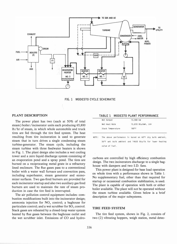
FIG. 1 MODESTO CYCLE SCH EMATIC
PLANT DESCRIPTION TABLE 1 MODESTO PLANT PERFORMANCE
The power plant has two (each at 50% of total steam) boiler /incinerator units each producing 65,800 Ib/hr of steam, in which whole automobile and truck tires are fed through the tire feed system. The heat resulting from tire incineration is used to generate steam that in turn drives a single condensing steam turbine-generator. The steam cycle, including the steam turbine with three feedwater heaters is shown in Fig. 1. The plant design also includes a wet cooling tower and a zero liquid discharge system consisting of an evaporation pond and a spray pond. The tires are burned on a reciprocating metal grate in a refractory lined enclosure. The flue gases pass to a conventional boiler with a water wall furnace and convection pass, including superheater, steam generator and economizer surfaces. Two gas-fired burners are provided for each incinerator startup and also two auxiliary gas fired burn�rs are used to maintain the rate of steam production in case the tire feed is interrupted.
The air pollution control equipment includes: combustion modifications built into the incinerator design; ammonia injection for NOx control; a baghouse for particulate control; and a wet scrubber for S02 control. Stack gases are reheated by a closed-loop water system heated by flue gases between the baghouse outlet and the wet scrubber inlet. Emissions of CO and hydro-
336
Net Output 13.900 kW
Net Heat Rate 13.810 Btu/kWh. LHV
stack Temperature 1800r
NOTE: The above performance Is based on 600r dry bulb ambIent.
56°r wet bulb ambIent and 14650 Btu/lb for lower heatIng
value of fuel.
carbons are controlled by high efficiency combustion design. The two incinerators discharge to a single baghouse with dampers and two I.D. fans.
This power plant is designed for base load operation on whole tires with a performance shown in Table 1. No supplementary fuel, other than that required for startup or occasional combustion stabilization, is used. The plant is capable of operation with both or either boiler available. The plant will not be operated without the steam turbine available. Given below is a brief description of the major subsystems.
TIRE FEED SYSTEM
The tire feed system, shown in Fig. 2, consists of two (2) vibrating hoppers, weigh station, metal detec-

... VIBRATING HOPPER
CAROUSEL
... VIBRATING HOPPER
FOUR ZONE STAGING
CONVEYORS
•
BOILER 1
BOILER 2
FIG. 2 MODESTO TIRE FEED SYSTEM
tor, conveyor systems, accumulator carousel, two lockhoppers on each of two boilers, and two control stations, one located near the vibrating hopper, and the other near the lockhoppers. This system is capable of providing continuous tire feed to the tire incinerators and reducing the tire feed rate if a boiler trips. Tires containing rims, and oversized tires that cannot fit through the boiler lockhopper, will not be permitted to enter the incinerator and are removed at the reject zone of the conveyor.
Tires are introduced into the system at the vibrator hopper units. These tires enter the vibrating conveyors singly at a controlled rate determined by the control system. Tires are transported, one at a time, to a scale where they are weighed and then sized. This data is
337
stored into a control system register for each individual tire. As a tire is processed, it is examined for excessive metal content and the data stored in the memory as a go or no-go bit. The discharge rate and the variable speed of the main belt conveyor allow the control system to control the pounds of rubber presented to the carousel prior to the lockhoppers. The carousel serves to distribute tires to the individual lockhoppers, and to store any excess tires arriving from the belt conveyor. The lockhoppers serve to isolate the high temperature boiler gases. During normal operation, tires are transported directly to staging conveyors prior to the infeed of each lockhopper as illustrated in Fig. 2. The four-zone staging conveyors upstream of each hopper are kept full at all times to ensure timely feed

FIG.3 BOILER/INCINERATOR
into the lockhoppers. Tires which cannot be immediately introduced into the staging conveyors at one of the lockhoppers are stored temporarily on the accumulator carousel.
As the system receives a signal from a lockhopper, one or two tires will advance forward from the staging conveyor into the hopper. The number of tires entering the hopper is determined by size and weight. As a tire or tires enter, a signal is given to the control system indicating a new weight is available to be read. This weight is retained until the next batch of tires is ready for entry into the lockhopper.
338
BOILERS
The incinerator has reciprocating grates, hydraulic grate drives, .steel structure, lining, feeding chutes, wet slag removal plant, combustion and cooling air systems, two (2) startup fuel gas burners and two auxiliary fuel gas burners. The flue gas from each incinerator passes through a boiler to generate superheated steam. Each boiler can be operated continuously at a, superheater steam flow not less than 65,800 lb/ hr with feedwater entering a 305"F and with a superheater steam outlet pressure of 975 psig at 932°F with

FIG.4 MODESTO FLUE GAS CLEANUP SYSTEM
5% blowdown from the steam drum, 100% excess air, 77°P ambient temperature. A schematic of the boiler is shown in Pig. 3.
FLUE GAS CLEANING SYSTEM
The flue gas cleaning system removes particulates, hydrogen chloride and sulfur dioxide from the flue gas. The major subsystems are particulate removal, gas absorption, reheat, reagent storage and preparation and dewatering subsystems, as shown in Pig. 4. NOx is controlled by injecting air/ammonia mixture into the boiler at one or more of the four injection nozzle zones located at different elevations on the sidewalls of the boiler. Ammonia concentrations are controlled by a thennal DeNOx system.
The particulate removal system consists of a single reverse-air fabric filter to remove particulates. The fabric filter consists of eight isolatable compartments, each with 315 8-in. diameter filter bags. Particulates are collected on the inside of the bags as the flue gas passes through the bag. The fabric filter is designed to handle maximum flue gas flow with one compartment off-line for cleaning and one compartment off-line for maintenance. A single reverse air fan is provided. The fabric filter is supplied with a 100% flue gas flow bypass
339
plenum. S03 in the flue gas will react with excess ammonia in the flue gas and fonn ammonium sulfate and bisulfate. If this reaction occurs after the fabric filter, additional SO 3-based particulates may be emitted from the system. If the reaction occurs before the fabric filter, the additional S03-based particulates will be collected in the fabric filter. Location of the reaction occurrence is largely determined by the ratio of ammonia to SO 3 in the flue gas and the temperature of the flue gas.· A water spray system is provided to cool the flue gas as required to achieve adequate NH3/S03 reaction ahead of the fabric filter.
Flue gas from the fabric filter passes through the two I.D. fans and is processed in a spray tower absorber where S02 and HCI are removed using slaked lime as the chemisorbent. The reaction products fonned are calcium sulfate (gypsum) as a solid and calcium chloride as a soluble salt. The flue gas enters the spray tower absorber and flows upward, countercurrent to a descending spray of recycle slurry droplets containing sufficient alkali to react with the HCI and S02 in the entering flue gas. Intimate contact of the flue gas with the recycle slurry occurs in three staged spray zones resulting in the removal of greater than 97% of the S02 and HCI in the entering flue gas. The treated flue gas leaves the uppennost spray zone and enters the absorber outlet duct which is equipped with a two-

stage high efficiency mist eliminator designed to remove small droplets entrained by the rising flue gas. After passing through the mist eliminator, the flue gas is reheated to avoid a visible stack plume by circulating hot water through a series of reheat tubes located in the outlet duct. Once reheated, the flue gas is fed to the stack.
As the acid components in the flue gas are absorbed in the recycle slurry, the slurry pH tends to decrease. To neutralize the HCI and absorbed S02' and to maintain a constant pH required to promote absorption, lime is added to the reaction tank on direct pH control. Air is also forced at sufficient flow and pressure to oxidize essentially 100% of the S02 reaction product to gypsum. An emergency flue gas quench system is also provided to quench the gas during power outage. Emergency power is supplied to the quench pump automatically upon power failure.
A complete reagent system for receiving, storing, feeding, slaking and metering X in. pebble quicklime is provided. Quicklime (CaO) is hydrated to Ca(OH)2 in the lime slaking system. This milk of lime is stored in an agitated tank and fed to the absorber recyclF tank, on demand, to maintain the required pH. The removal of gypsum and calcium chloride is accomplished by bleeding a small stream of recirculating slurry from the recycle pump to a hydro-cyclone system for dewatering.
STEAM TURBINE GENERATOR
The steam turbine generator system has a condensing steam turbine, a reduction gear, a totally enclosed water to air cooled synchronous generator, a brushless excitation system, gland seal system, lube oil system with dual coolers and pumps and a vibration detection system consisting of probes, proximeters, cables, junction box, power supply and relays. The steam turbine instrumentation includes a low exhaust vacuum alarm and a high exhaust temperature alarm. Generator controls include an insert panel, governor, servo amplifier, turbine protective relays, interposing relay for trip solenoid, and emergency trip pushbutton. The steam turbine generator is shown in Fig. 5.
CONDENSER
The condenser is a shell and tube, two pass surface condensing heat exchanger, and has a hot well located below the condenser shell. A steam driven air ejector package is supplied to maintain vacuum pressure in the condenser. The system includes first and second stage holding jet, integral inter- and after-surface con-
340
denser, suction manifold, hogging ejector, accessories and valving.
COOLING TOWER
The cooling tower is a counterflow, mechanical induced draft type that provides cooling water to the steam turbine condenser and additional auxiliary equipment. The unit consists of three cells, each containing one single speed fan, which can be operated independently of the other cells and is capable of being repaired, maintained and cleaned with all remaining cells in service.
ASH HANDLING SYSTEM
The ash handling system is designed to remove fly ash from the two boilers and the baghouse and transport it to one common storage silo where it will be held until periodic removal. Ash transport is attained through two mechanical vacuum exhausters. The fly ash contains a significant concentration of zinc oxide, and is a saleable byproduct to resmelters for recovering zinc.
Bottom ash and slag from the two boilers is collected in a conventional wet drag-chain conveyor. This material comprises mostly steel slag with some short pieces of wire beads and belting material. Carbon content in the bottom slag is less than about 0.2%.
ELECTRICAL SYSTEM
The steam turbine generator is connected to the 13.8-115 kV main stepup transformer through a 1200 A generator breaker. The high voltage side of the stepup transformer is connected to the 115 k V utility system through a 1200 A oil circuit breaker and oil filled metering units. Two station auxiliary power transformers, 13,800-480 V, are connected to the 13.8 k V bus between the steam turbine generator breaker and the main step-up transformer. Auxiliary power may also be supplied from a diesel generator during emergency or black start.
CONTROL SYSTEM
The plant utilizes a microprocessor based distributed control system (DCS) and programmable logic controller (PLC) for the control, protection, sequencing and on-line monitoring of selected plant equipment from the central control room as shown in Fig. 6. This

341
0::: o I-� LLJ Z LLJ (.!' LLJ Z Q5 0::: :::I I-� L'3 lV) o lV) LLJ o o �

....,
""'"
N
TIR
E IN
CIN
ERA
TOR
FEED
G
RA
TE,
AS
H.
#1
BO
ILER
, D
ENO
X
#1
I I JL
G
RA
TE
SOO
T A
SH
BLD
WER
H
OPP
ER
PAN
EL
PAN
EL
-�
ST
ARTU
P TI
RE
AU
XIL
IAR
Y FE
ED
BF'rl�EER
PAN
EL
-TI--
PAN
EL -IT-
-I C
ON
TRO
L EQ
UIP
MEN
T R
OO
M
TIR
E IN
CIN
ERA
TOR
FE
ED
GR
ATE
, A
SH.
112
BO
ILER
, D
ENO
X
#2
11 JL
G
RA
TE
SOO
T A
SH
BLO
WER
H
OPP
ER
PAN
EL
PAN
EL
"---
..... ..-
r-..
.. -ST
ARTU
P TI
RE
AU
XIL
IAR
Y FE
ED
BU
RN
ER
PAN
EL
FLA
ME
If
PAN
EL
--
--
--1·
- f-
BAG
HO
USE
SC
RU
BB
ER
I
•
FUEL
•
C
OO
LIN
G W
ATE
R
•
CO
ND
ENSE
R
•
CIR
C.
WA
TER
•
H
OTW
ELL
•
CO
OLI
NG
TO
WER
•
D
EAER
ATO
R
•
DEM
INER
ALI
ZER
•
FS
H
•
STEA
M I WA
TER
SAM
PLIN
G
•
BFP
•
EM
ISSI
ON
MO
NITO
RIN
G
•
CO
ND
o PU
Mp
. I
NS
TR.
AIR
•
ETC
. •
ETC
.
MEC
H.
AU
X.
B.O
.P'
MEC
H.
II ST
EAM
WA
TER
SA
MPL
ING
PA
NEL
r-..
.
DEM
IN
PAN
EL
'---
B.O
.P'
ELEC
T.
Jl
REL
AY
PAN
EL -
-- .... �
--
-..
.. -------
-- ---
DC
S/P
LC I
NP
UT/
OU
TPU
T AN
D C
ON
TRO
L C
ABIN
ETS
-STEA
M
GEN
ERA
TOR
TU
RB
INE
..J.
PRO
T.
RELA
Y PA
NEL
--
--
... .c-
EXC
ITO
R
PAN
EL I � -1-- I
----
----
-----
------
-----
--- -
------
------
----
---- --
---
-- -
CO
NTR
OL
RO
OM
I SOO
T B
LOW
ER
PAN
EL
BO
ILER
1
GR
ATE
I G
RA
TE I
BO
ILER
B
OIL
ER
MG
MT.
M
GM
T.
PAN
EL 1
PA
NEL
2
I SOO
T B
LOW
ER I
PAN
EL
BO
ILER
2 A�
TI
RE
FEED
B
OIL
ER
SYST
EM
1 1
CR
T KE
YBO
AR
D
CR
T C
RT
KEYB
OA
RD
KE
YBD
AR
D
OP
ERAT
OR
CO
NSO
LE
I PR
INTE
R I
�I P
RIN
TER
I
,
BO
ILER
2
TIR
E FE
ED
sYSTE
M
2'
FIG
. 6
M
OD
ES
TO
PL
AN
T C
ON
TR
OL
SY
ST
EM
AU
XIL
IAR
Y C
ON
TRO
L PA
NEL
•
EMM
ISSI
ON
REC
OR
DER
•
G
ENER
ATO
R SY
NC
. •
G
ENER
ATO
R E
XC
IT.
•
ELEC
TRICA
L M
IMIC
•
EM
ERG
ENCY
TR
IP
•
MIS
C.

equipment includes the necessary sensors, control equipment cabinets, final control elements and operator interface units for incinerator/boiler, plant auxiliaries and balance of plant. In addition the DCS will also perform selected monitoring, and/or supervisory control functions for the steam turbine generator, burner management system, fire protection system, water treatment system, instrument and service air system, chemical injection, incinerator grate, chlorination system, ash handling system and tire handling systems. The DCS operator interface units in the central control room consist of an operator console containing three CR Ts and three keyboards through which the operator will control and monitor the operation of the plant. An auxiliary panel is also provided in the central control room for an emission monitoring recorder, steam turbine inlet control, turbine-generator vibration monitoring system, generator synchronization equipment, electrical distribution system control and monitoring equipment, emergency diesel generator, sootblower insert for the scrubber regenerative heater and a tire handling system operator interface unit.
Total tire weight and count are retained for each boiler on a continuous basis with provisions for secured manually requested reset. These data are made available to personnel through an operator interface terminal located in the control room. Run status and alarm conditions are directed to the operator interface terminal. Tires feed control panels are located at both the vibrating hoppers and at the lockhoppers.
The control system uses a redundant programmable logic controller (PLC) which performs the necessary sequencing, interlocking and protective logic required by the tire feed system. The tire feed control monitors the tire consumption of each boiler and controls the tire feed to the carousel to maintain the tire inventory in balance. A tire batch weight signal is provided by the tire feed system to the boiler fuel feed control based upon the number and size of tires in the batch.
A redundant microprocessor based PLC is provided to implement the interlocking, sequential and protective logic associated with the plant equipment. Discrete input and output signal to/from field equipment is wired to the PLC cabinet. Operator command signals to the PLC are communicated from the DCS over a redundant serial data link to permit the starting/stopping of plant equipment. Similarly equipment status information, e.g., running/stopped, open/ closed, etc. , is communicated to theDCS over the serial data link. The DCS has redundant controllers, power supplies, communication data bus and operator interface controls. The plant control strategy is to utilize a turbine follow mode of control during normal plant operation.
343
This mode of control utilizes the steam turbine inlet control valve to regulate steam pressure and the boiler fuel and air flow controls to regulate steam flow.
SPRAY AND EVAPORATION POND SYSTEM
The Modesto site requires a zero waste water discharge system. Two ponds are provided at the site. The purpose of the ponds is to evaporate the liquid effluent from the plant. One pond is the spray pond and the other is a solar evaporation pond. The spray pond receives liquid discharges from the wet scrubber and the demineralizer system. The spray evaporation pond receives blowdown from the spray pond and the effluent of the sanitary waste treatment system. Each pond is lined with a Hypalon liner. The spray pond uses low pressure spray nozzles to spray water droplets into contact with surrounding air, thereby causing the droplets to partially eva,porate and the air to absorb heat energy from the water droplets, resulting in a temperature drop of the water. To increase the evaporation rate, the spray pond design includes the spray pumps and heat exchangers which continuously add heat from the auxiliary cooling system to the water to maintain the water temperature well above the wet bulb temperature.
ENVIRONMENTAL EMISSIONS
The Modesto plant, located in Stanislaus County, California, has stringent environmental emission requirements. The air permit states the following pollutant emission levels shall not be exceeded.
Pollutant
NOx CO Particulates SOx HC
lb-/day
500 346.4 1 1 3.0 250 1 48.4
Preliminary startup tests performed to date indicate that the plant has environmental emission levels within above requirements.
ACKNOWLEDGMENTS
The authors would like to acknowledge and express their appreciation to the Modesto design team members, J. Trypaluk, B. Fick, and W.B. Pifer for their contribution to this project.