modified material properties in curved panels through
TRANSCRIPT

Modified Material Properties in Curved Panels Through Lamina EmergentTorsional Joints*
Trent Zimmerman1, Jared Butler1, Dallin Frandsen1, Dakota Burrow1, David Fullwood1,Spencer Magleby1, and Larry Howell1
Abstract— Compliant joints have a number of advantagesthat make them suitable for highly constrained design prob-lems. While much work has been done on the design ofcompliant joints manufactured from planar sheet materials,this work focuses on the design of cylindrically-curved joints.A method for using lamina emergent torsional (LET) jointsto increase energy storage efficiency in curved sheet materialsis presented. A numerical model is provided for predictingthe stiffness and maximum applied moment of a curved LETjoint. Predicted curved LET joint stiffnesses and maximummoments are utilized to create shape factors that produce aneffective modulus of elasticity and an effective modulus ofresilience. For a given case, the effective modulus of elasticityis shown to decrease by about three orders of magnitude whilethe effective resilience decreases by approximately one orderof magnitude. Designers can use this information to tailormaterials to fit design requirements or to select alternativematerials that were previously unsuited for an application.
I. INTRODUCTION
Compliant joints are capable of solving highly con-strained design problems due to their potential formonolithic and compact design, low mass, scalability,and suitability for harsh environments. They serve asa base component of compliant mechanism design andallow designers to create mechanisms with complexmovements that exhibit these properties, making themsuitable for highly constrained applications [1] such asfor space [2], minimally invasive surgery [3], or micro-electro mechanical systems [4]. A particular benefit ofcompliant joints is their capacity for energy storage. Acompliant joint can be considered a traditional pin jointwith an attached torsional spring [5]. A mechanism thatincorporates compliant joints will be influenced by thestrain energy in this spring. By identifying the maximumamount of energy that can be safely stored within thejoint without plastic deformation, mechanisms can bedesigned to use the spring behavior of the joint toperform desired tasks, such as aid in actuation [6] orprovide multistable behavior [7].
One method of creating compliant joints with energystorage capabilities is through the Lamina EmergentTorsional (LET) joint, a combination of local bendingand torsional members that together produce a globalhinge motion [8]. These joints can be used to create
*This work was supported by the U.S. National Science Foun-dation.
1Authors are with the Department of Mechanical Engineering,Brigham Young University, Provo, UT, USA [email protected]
mechanisms that deploy from a surface, such as the four-bar mechanism shown in Figure 1. While traditional LETjoints are formed from planar sheet material, designerswould benefit from an expansion to include LET jointsfabricated from a singly curved sheet, as shown in Fig-ure 2. A curved LET joint would allow for energy storagewithin joints of mechanisms created out of pre-existingcurved members, such as shafts, rocket bodies, needles,or wheels. Energy-storing devices developed from thesesurfaces could enable new or multifunctional capabilities,such as shafts with contained self-retracting deployablefins, needles with bistable anchoring devices, or impact-absorbing mechanisms on the surface of vehicles.
The bending and torsional members that comprisea LET joint are created by removing material from asheet which in turn significantly reduces stiffness andinfluences the amount of strain energy and where strainoccurs. Because this behavior is largely influenced by thegeometry of these compliant segments, material selectionshape factors provide an effective method of comparingLET joint energy storage properties with changes injoint stiffness. Energy stored per unit volume beforeyield, known as the material’s modulus of resilience,allows for design with direct consideration of strainenergy limits in the material. By altering the geometryof the substrate material, a “new” material can becreated through the application of shape factors [9]. Thisnew material can be considered geometrically identicalto the original substrate but with adjusted (effective)material properties due to the changed shape. Withthese effective material properties, designers could makerapid comparisons between altered materials for designapplications where energy storage and flexibility aredesirable.
This paper proposes a method to derive an effectivemodulus of resilience and effective modulus of elasticityin curved sheet materials by developing multiple shapefactors relating the stiffness and maximum moments of asingly curved LET joint to those of the uncut substrate.These shape factors will be derived by first defining thefundamental design of curved LET joints aligned longi-tudinally on a cylinder. Analytical and numerical modelswill be provided along with verification. Modification ofmaterial properties will be demonstrated on an Ashbyplot [9] by applying the shape factors to compare changesin modulus of resilience against changes in modulus ofelasticity for various materials.
978-1-5386-6380-6/18/$31.00 ©2018 IEEE
Proceedings of the 4th IEEE/IFToMM Int. Conf. on Reconfigurable Mechanisms and Robots (ReMAR 2018), Delft, 20-22 June 2018

(a) Stowed. (b) Deployed.
Fig. 1. A four-bar Lamina Emergent Mechanism (LEM) fabricated with planar LET joints.
Fig. 2. A mechanism created from a cylindrically-curved sheetwith incorporated curved LET joints.
II. BACKGROUNDThe curved LET joint model presented in this paper is
enabled through design methods and results obtained inprevious investigations on compliant mechanisms, laminaemergent mechanisms, and lamina emergent torsionaljoints. A summary of relevant background informationin these areas is discussed in this section.
A. Compliant MechanismsTraditional mechanisms transfer motion, force, or
energy from an input to an output through rigid linksand joints. Compliant mechanisms, conversely, achievemechanism function from the deflection of flexible mem-bers [5]. Compliant mechanisms continue to demonstratetheir potential for monolithic design [10], high-precisionmovement [11], scalability, impact-resistant design [12],
low-cost production [13], reliable performance in harshenvironments [14], and energy storage [15]. The highlynonlinear behavior of compliant mechanisms can makedesign challenging, but the development of methods toanalyze this nonlinear behavior [5], [16], [17], [18] hasenabled optimization methods to predict their behav-ior [19], [20], [21], [22], [23]. These tools have facilitatedthe design of compliant mechanisms and opened thedoors to a variety of new applications. This work willutilize the pseudo-rigid body model [5] to enable theanalysis of curved LET joint stiffness to predict jointbehavior.
B. Lamina Emergent MechanismsLamina Emergent Mechanisms (LEMs) are mecha-
nisms fabricated from planar, thin sheet materials thatdeploy out of plane to achieve their function. They area subset of ortho-planar mechanisms and are compliantmechanisms [24] which makes them useful in a numberof applications not suitable for traditional mechanisms.These mechanisms possess many of the same benefits asLET joints which enable the design of mechanisms suchas microelectro-mechanical systems [25] and disposabledevices [26].
C. Lamina Emergent Torsional JointLET joints are compliant joints made from a planar
layer of material which rotate from a plane [8]. LET jointsprovide rotation by transferring the bending motionbetween two panels to the twisting of torsional barswhich lie parallel to the joint axis (see Figure 3).They are capable of large deflections and energy storagewhich make them practical in many micro and macroapplications.

(a) Planar outside LET joint. (b) Planar inside LET joint.
(c) Curved outside LET joint. (d) Curved inside LET joint.
Fig. 3. The outside (a) and inside (b) LET joints. The segments placed in torsion and bending when the joint is rotated are labeled.
There are several types of LET joints which havebeen designed to meet specific desired motions or con-straints [27], [28], [29], [30]. The outside and insideLET joints are commonly used in LEM applications [31]and are shown in Figure 3(a) and 3(b). These twoconfigurations will be studied for curved LET joints.Because planar LET joints maintain many characteristicssimilar to curved LET joints, extending principles ofplanar LET design to curved surfaces represents the nextstep in advancing LET joint capabilities.
III. METHODSThis section describes a method to create “new”
materials by applying LET joints to curved panels. Sec-tion III-A identifies the stiffness and resulting momentand deflection characteristics of a curved LET joint.Section III-B utilizes the identified joint stiffness tocreate an effective modulus of elasticity and effectivemodulus of resilience for curved LET joints. Section III-C describes performance indices as a method of usingthe derived effective modulus of elasticity and modulusof resilience to aid in rapid comparison of materials fordesign applications.
A. Joint MechanicsBoth curved and planar LET joints incorporate bend-
ing and torsional segments, which can be treated as
springs in parallel and series. Though the stiffness ofthe individual segments of the curved LET joint needto be accommodated for curvature, using a structuresimilar to that of existing planar LET methods [8] willpermit the equivalent stiffness of a curved LET jointto be predicted. The curved LET can be modeled asa revolute hinge coupled with a torsional spring. Themoment-deflection behavior of the joint rotated aboutits longitudinal (hinge) axis is then expressed by
M = keqα (1)
where keq is the equivalent stiffness per unit length of allof the torsional and bending segments of the joint and αis the deflection angle of the joint. If all of the torsionalsegments are equal in stiffness, keq can be found for theoutside LET joint as
keq =2ktkb
kt + 2kb(2)
and for the inside LET joint as
keq =ktkb
5kt + 4kb(3)
where kt and kb are the stiffnesses of a torsional segmentand a bending segment, respectively.
The differences between the planar and curved LETcan be seen in the differing geometries of the bending

and torsion members shown in Figure 3. The bendingsegments of the curved LET joint can be modeled asinitially curved beams with rectangular cross sections.They are, however, assumed to be short enough tobe approximated as small-length flexural pivots, whichpermits application of the pseudo-rigid body model [5] todetermine the bending stiffness of the bending segmentsas
kb =EIbLb
(4)
where E is the Young’s modulus of the material, Ib isthe second moment of area of the bending members, andLb is the arc length of the small-length flexural pivotmeasured along the centroidal axis.
The cross section of the torsional segments is anannular sector as shown in Figure 4. The torsionalstiffness of a beam with an annular cross section canbe found numerically through the summation [32]
kt =4G
Lt
∞∑m=1
Fmsinγmθ0
γm
[r4o − r4i
4− Am
r2+γmo − r2+γm
i
2 + γm
− Bmr2−γmo − r2−γm
i
2− γm
](5)
with
γm =(2m− 1)π
2θ0(6)
Am =r2+γmo − r2+γm
i
r2γmo − r2γm
i
(7)
Bm =rγmo r2i − rγm
i r2o
r2γmo − r2γm
i
(riro)γm (8)
Fm =−4(−1)m
θ0γm(γ2m − 4)
(9)
where G, Lt, ro, ri, and θ0 are the torsional rigidity,length of torsion member, outer radius, inner radius,and half the cross-sectional sweep angle, respectively.Additionally, r, w, and t are the centroidal radius,centroidal arc length, and thickness, respectively.
With the bending and torsional stiffnesses defined forthe curved LET joint, the equivalent stiffness of boththe outside and inside LET joints can be identified usingEquations 2-3.
For the analyses done in this work, the geometricparameters, material properties, and deflection angleused are provided in Table I. The listed geometricparameters are related to an outside LET joint inFigure 5. Additionally, in order to prevent geometricand numerical irregularities (e.g. due to a cross sectionwrapping in on itself), the following constraints areimposed:
θ0max= π (10)
ro
ri
rwt
Ɵo
t
Fig. 4. The annular sector with parameters labeled. The torsionmembers of the curved LET have this cross section.
tmax = 2r (11)
wmax = 2πr (12)
w ≥ t (13)
Error in the predicted torsional stiffness may preventaccurate representations of the overall joint. To verify theaccuracy of the predicted stiffness of only the torsionalmembers, given by Equation 5, a comparison is madewith finite element model results and is displayed inFigure 6. Using beam elements in ANSYS, an angulardeflection load α was applied and the reaction momentwas recorded as the thickness t was varied with respect towidth wt. This range of thickness represents the extremesof the cross sectional geometry, where the maximumvalue of t/w corresponds to a circular sector and theminimum to a thin annular sector. A maximum valuefor θ0 allowed by the constraint equations 10-13 forthe full range of thicknesses was used. The reactionmoment in the numerical model was calculated usingEquation 1 with the stiffness of the individual membersbeing used rather than keq. The results show that for0 < t/wt < 1, the error is less than 3%. Based on theseresults, Equation 5 is sufficiently accurate for this work.
Next, the full curved LET model is verified witha curved outside LET joint employing the geometrylisted in Table I. The joint was curved about thelongitudinal (hinge) axis, based on the centroidal axis
TABLE IExample curved LET Geometry Parameters.
Parameter Valuet 0.5 mmr 10 mmwt 1 mmwb 1 mmlt 40 mmlb 1 mmE 200 GPaν 0.29α 20o

σy
τxy
τxy
τyx
τyx
σy
lt
wt
wb
lb
Fig. 5. Labels for geometric parameters of a LET joint. Notethat lb and wt are measured as out-of-plane arc lengths. A stresselement at the point of maximum stress in the joint is also shown.
Fig. 6. A comparison of the numerical and finite element modelresults for the curved torsion members. An angular deflection loadwas applied and the reaction moment of the beam was recorded asthe thickness t with respect to width wt was varied. The resultsshow little error using Equation 5.
of the substrate. Using solid elements in ANSYS, anangular deflection load α was applied and the reactionmoment was recorded as the joint curvature K was variedin the range of 0 < K < 2.09, shown in Figure 7.This range of curvature simulates a joint curved froma planar state to a full cylinder with a longitudinal slit.The results show less than 2% relative error across thefull range of joint curvature. Furthermore, the reactionmoments of the finite element model are lower than thoseof the numerical model, meaning that the numericalmodel is conservative for calculating maximum stress,
Fig. 7. A comparison of numerical and finite element model resultsfor an outside LET joint, using Equation 2. An angular deflectionload was applied and the reaction moment was recorded as the jointcurvature was varied. The results show little error using Equation 2.
deflection, etc. Based on these results, Equations 2-5are sufficiently accurate for predicting the equivalentstiffness of a curved LET joint, particularly in the designphase.
B. Shape FactorsShape factors provide a method for quantifying effec-
tive material properties based on geometric alterations.For example, a beam with a rectangular cross section of agiven length and modulus of elasticity will have a definedstiffness. If a designer seeks to maximize stiffness, thecross-sectional area could be rearranged into an I shapeto create a beam with a greater stiffness. Since stiffnessand modulus of elasticity have a linear relationship, theratio of new stiffness to original stiffness creates a shapefactor that can be multiplied by the material’s modulusof elasticity to create an effective modulus of elasticity.This effective modulus is representative of a beam thathas the same shape as the original (rectangular) beam,but exhibits the performance of the altered (I) beam.Through this method, many “new” materials can be de-veloped that exhibit properties previously unattainablein other materials.
Elastic energy storage is constrained by the modulus ofresilience of a given material. Resilience is a function ofa material’s yield strength Sy and modulus of elasticityE and is found by integrating the material’s stress-straincurve from zero to the elastic limit. While the resilienceof any material can be found through this integration,this work will demonstrate principles of the change inresilience through application in only simple linear elasticmaterials. Under this assumption, the resilience is thendefined as
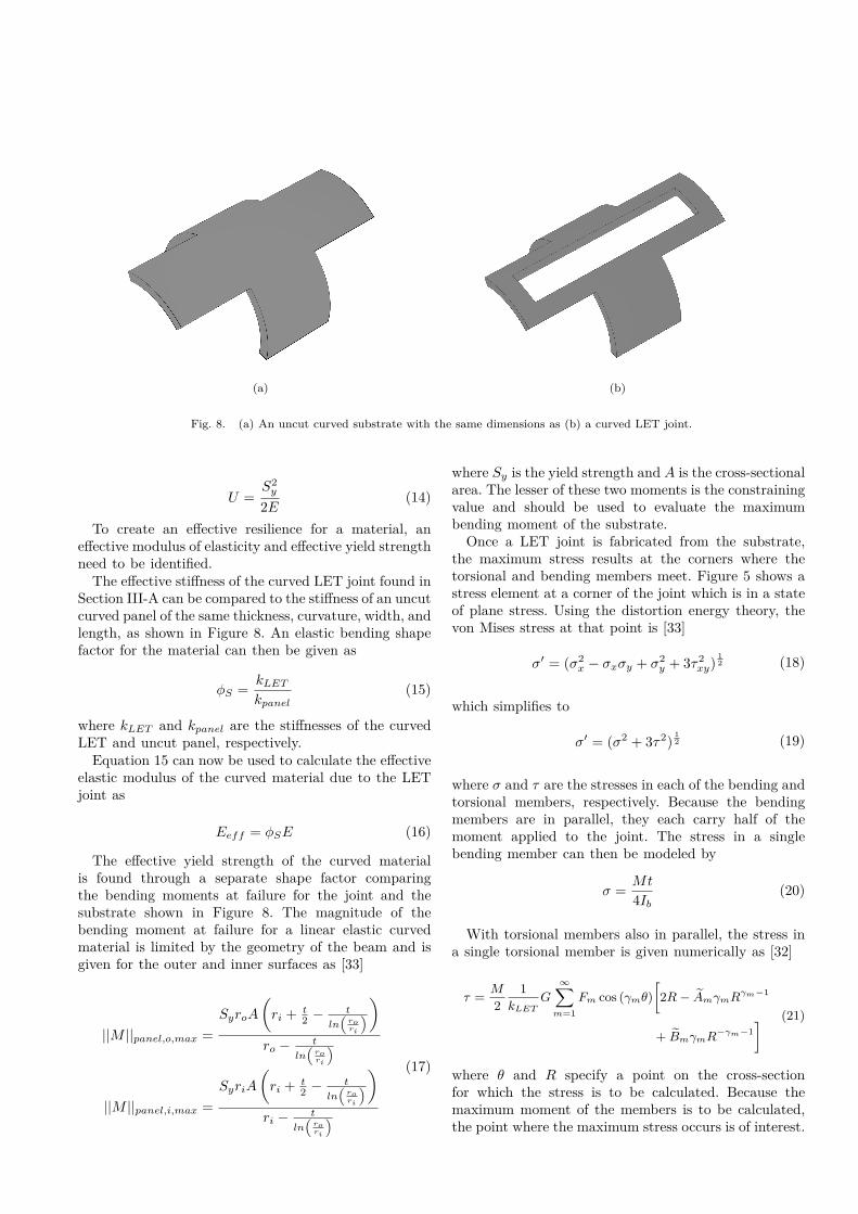
(a) (b)
Fig. 8. (a) An uncut curved substrate with the same dimensions as (b) a curved LET joint.
U =S2y
2E(14)
To create an effective resilience for a material, aneffective modulus of elasticity and effective yield strengthneed to be identified.
The effective stiffness of the curved LET joint found inSection III-A can be compared to the stiffness of an uncutcurved panel of the same thickness, curvature, width, andlength, as shown in Figure 8. An elastic bending shapefactor for the material can then be given as
ϕS =kLET
kpanel(15)
where kLET and kpanel are the stiffnesses of the curvedLET and uncut panel, respectively.
Equation 15 can now be used to calculate the effectiveelastic modulus of the curved material due to the LETjoint as
Eeff = ϕSE (16)
The effective yield strength of the curved materialis found through a separate shape factor comparingthe bending moments at failure for the joint and thesubstrate shown in Figure 8. The magnitude of thebending moment at failure for a linear elastic curvedmaterial is limited by the geometry of the beam and isgiven for the outer and inner surfaces as [33]
||M ||panel,o,max =
SyroA
(ri +
t2 − t
ln(
rori
))ro − t
ln(
rori
)
||M ||panel,i,max =
SyriA
(ri +
t2 − t
ln(
rori
))ri − t
ln(
rori
)
(17)
where Sy is the yield strength and A is the cross-sectionalarea. The lesser of these two moments is the constrainingvalue and should be used to evaluate the maximumbending moment of the substrate.
Once a LET joint is fabricated from the substrate,the maximum stress results at the corners where thetorsional and bending members meet. Figure 5 shows astress element at a corner of the joint which is in a stateof plane stress. Using the distortion energy theory, thevon Mises stress at that point is [33]
σ′ = (σ2x − σxσy + σ2
y + 3τ2xy)12 (18)
which simplifies to
σ′ = (σ2 + 3τ2)12 (19)
where σ and τ are the stresses in each of the bending andtorsional members, respectively. Because the bendingmembers are in parallel, they each carry half of themoment applied to the joint. The stress in a singlebending member can then be modeled by
σ =Mt
4Ib(20)
With torsional members also in parallel, the stress ina single torsional member is given numerically as [32]
τ =M
2
1
kLETG
∞∑m=1
Fm cos (γmθ)
[2R− AmγmRγm−1
+ BmγmR−γm−1
] (21)
where θ and R specify a point on the cross-sectionfor which the stress is to be calculated. Because themaximum moment of the members is to be calculated,the point where the maximum stress occurs is of interest.
θ and r are then set to values of 0 and ro, respectively,which correspond to the center of the outermost surface.Setting σ′ = Sy, substituting Equations 20-21 intoEquation 19, and solving for M , the maximum momentbefore yield in the curved LET joint becomes
MLET,max =Sy[
9wbt
4 − 3G2
4kLET
(∞∑
m=1
Fm
[2ro−
Amγmrγm−1o + Bmγmr−γm−1
o
])2] 12
(22)
Equations 17 and 22 can then be used to derivethe strength efficiency shape factor for a linear elasticmaterial as
ϕB =MLET,max
Mpanel,max(23)
An effective yield strength is then given by multiply-ing the strength efficiency shape factor with the yieldstrength of the uncut curved substrate:
σeff = ϕBSy (24)
The effective modulus of resilience of a linear-elasticcurved member altered by a LET joint can now becalculated by substituting the effective modulus fromEquation 16 and effective yield strength from Equa-tion 24 into Equation 14 as
Ueff =(ϕBSy)
2
2ϕSE(25)
Equation 25 can now be applied to various linear-elastic materials to demonstrate their energy storage andstiffness behaviors after application of the curved LETjoint.
C. Performance IndexMaterial selection becomes more complex when a
design must meet multiple criteria. Performance indicescan provide a systematic material selection process thatweights multiple objectives, resulting in quantified andcomparable performance values. For example, a designerseeking to create a light, stiff beam would create amaterial index relating the modulus of elasticity E withthe density of the material ρ to create a material indexE/ρ [9]. Maximizing this value would allow a designerto select a material that best meets stiffness and weightrequirements for a given application.
The curved LET joint presented in this work is in-tended to provide high strain energy before failure whilemaintaining low stiffness for actuation. These competingconstraints create a multi-objective problem that may beaddressed with an appropriate performance index. Highenergy storage before yield, represented by the modulusof resilience, can be compared with the flexibility of the
material, represented by the modulus of elasticity, tocreate a performance index given as
P =U
E=
(Sy
E
)2
(26)
This material index provides the slope of lines that canbe drawn on a U vs. E Ashby plot to demonstrate mate-rial performance relative to the competing objectives ofenergy storage before yield and low stiffness. Materialsthat lie along the same material index line provide thesame performance with respect to the desired objectives.By convention, maximizing the material index results inimproved performance.
IV. RESULTS AND DISCUSSIONFigure 9 is a logarithmic Ashby plot which demon-
strates the changes in the modulus of resilience andmodulus of elasticity for various sample materials subjectto these material and geometric parameters. Grayscaleregions in the plot represent standard material propertiesand the colored regions represent effective material prop-erties after application of ϕS and ϕB . Since manufactur-ing limitations constrain these shape factors, the effectiveproperties in this case have been calculated based onwater-jet machining tolerances for polymers and metals(≥ 1mm). The envelopes for the remaining materialswere extrapolated accordingly. LET joint geometry andmanufacturing precision for each material should beconsidered before using the chart.
Here the effective modulus of elasticity of the materialsdecreases by approximately three orders of magnitude.Since stiffness is directly proportional to the modulusof elasticity, the LET joint may significantly reduce thestiffness of a curved member and allow for compliant mo-tion. The effective modulus of resilience of the materialhas decreased by approximately one order of magnitude.
The material performance index P is plotted onFigure 9 to demonstrate how materials can providemore efficient energy storage in the curved member byapplying a LET joint. Materials improve in performanceas they move toward the top left corner of the plot. Whileeach material has been adjusted by the same amountwith reference to its original value, it can be seen thatthe curved LET joint enables each material to improveits performance relative to the performance index.
With these results, designers can select suitable ma-terials for applications that would otherwise not havesufficient energy storage and stiffness characteristicswhile considering other design constraints. For example,a bistable mechanism designed for aerospace applicationscould require compliant joints fabricated in a metalmaterial to prevent outgassing and to minimize mass. Ifthe designer desires to use the strain energy in a joint toenable bistable behavior, the methods developed in thiswork could be employed to create shape factors reflectiveof their design. The changed properties could then be

Fig. 9. An Ashby plot of modulus of resilience vs. modulus of elasticity. Grayscale sections represent original material properties.Colored regions represent new (effective) material properties due to the curved LET joint. There is a marked decrease in the modulusof elasticity and a smaller decrease in the modulus of resilience.
plotted on an Ashby chart similar to Figure 9 to indi-cate whether their curved LET design will safely meetresilience constraints while still providing the desiredflexibility of the joint. The red dotted line on Figure 9demonstrates a possible change in material properties forthis example, assuming the geometry used in this work.
V. CONCLUSION
This research has demonstrated a method of increasingthe efficiency of energy storage in cylindrically-curvedsheet materials through the implementation of laminaemergent torsional joints. Shape factors provided ameans of quantifying the effects of geometric changesin a substrate, in this case, removing material to makea cylindrically curved LET joint. The joint was treatedas a ”new” material with effective material propertiesand improved energy storage efficiency relative to thesubstrate.
A numerical model has been presented and verifiedfor determining curved LET joint stiffness and maxi-mum moment. Formulas for predicting the stiffness andmaximum moment of an un-cut curved reference materialhave also been provided. With these, functions for shapefactors for the modulus of elasticity and the modulusof resilience were developed. These provide a means bywhich designers can rapidly select materials for designapplications using performance indices.
Using this method, specific shape factors based ongiven geometry were developed, and the resulting ef-fective modulus of resilience and modulus of elasticityfor various materials were represented on an Ashby plot.The resilience decreased by about an order of magnitude,while the stiffness decreased by approximately three or-ders of magnitude. These results indicate that a designerrequiring decreased stiffness while retaining much of theenergy storage capability can achieve it using curvedLET joints. They also show that designers can tailorstiffness and energy storage properties to alternativematerials that were previously not suitable for a givenapplication.
Various applications could benefit from the resultsof this work. Aeropace, surgical tools, defense, andconsumer products are just a few areas that may demandmonolithic, compactly stowed compliant joints. CurvedLET joints could be uniquely suited to satisfying thosedemands.
ACKNOWLEDGMENTThis paper is based on work supported by the U.S.
National Science Foundation and the U.S. Air ForceOffice of Scientific Research through NSF Grant No.EFRI-ODISSEI-1240417 and NSF Grant No. 1663345.
References[1] S. Henein, L. Rubbert, F. Cosandier, and M. Richard, The
Art of Flexure Mechanism Design. CRC Press, 2017.

[2] R. Fowler, L. Howell, and S. Magleby, “Compliant spacemechanisms: a new frontier for compliant mechanisms,” Mech.Sci, vol. 2, no. 2, pp. 205–215, 2011.
[3] S. Awtar, T. T. Trutna, J. M. Nielsen, R. Abani, and J. Geiger,“Flexdex™: a minimally invasive surgical tool with enhanceddexterity and intuitive control,” Journal of Medical Devices,vol. 4, no. 3, p. 035003, 2010.
[4] B. D. Jensen, L. L. Howell, and L. G. Salmon, “Introductionof two-link, in-plane, bistable compliant mems,” in Proceedingof the 1998 ASME Design Engineering Technical Conferences,DETC98/MECH-5837, 1998.
[5] L. L. Howell, Compliant mechanisms. John Wiley & Sons,2001.
[6] M. Cestari, D. Sanz-Merodio, J. C. Arevalo, and E. Garcia,“An adjustable compliant joint for lower-limb exoskeletons,”IEEE/ASME Transactions on Mechatronics, vol. 20, no. 2, pp.889–898, 2015.
[7] G. Chen, S. Zhang, and G. Li, “Multistable behaviors ofcompliant sarrus mechanisms,” Journal of Mechanisms andRobotics, vol. 5, no. 2, p. 021005, 2013.
[8] J. O. Jacobsen, G. Chen, L. L. Howell, and S. P. Magleby,“Lamina emergent torsional (LET) joint,” Mechanism andMachine Theory, vol. 44, no. 11, pp. 2098–2109, 2009.
[9] M. F. Ashby, Materials Selection in Mechanical Design, 4thEdition. Elsevier, 2011.
[10] D. F. Machekposhti, N. Tolou, and J. Herder, “Monolithicand statically balanced rotational power transmission couplingfor parallel axes,” in Microactuators and Micromechanisms.Springer, 2017, pp. 189–198.
[11] M. T. Pham, T. J. Teo, S. H. Yeo, P. Wang, and M. L. S.Nai, “A 3-D printed Ti-6Al-4V 3-DOF compliant parallelmechanism for high precision manipulation,” IEEE/ASMETransactions on Mechatronics, vol. 22, no. 5, pp. 2359–2368,2017.
[12] K. Y. Choi, A. Akhtar, and T. Bretl, “A compliant four-barlinkage mechanism that makes the fingers of a prosthetic handmore impact resistant,” in Robotics and Automation (ICRA),2017 IEEE International Conference on. IEEE, 2017, pp.6694–6699.
[13] H. M. Anver, R. Mutlu, and G. Alici, “3D printing of athin-wall soft and monolithic gripper using fused filamentfabrication,” in Advanced Intelligent Mechatronics (AIM),2017 IEEE International Conference on. IEEE, 2017, pp.442–447.
[14] J. Butler, S. Magleby, L. Howell, S. Mancini, and A. Parness,“Highly compressible origami bellows for microgravity drilling-debris containment,” in AIAA SPACE and Astronautics Fo-rum and Exposition, 2017, p. 5341.
[15] T. Bacek, M. Moltedo, J. Gonzalez-Vargas, G. A. Prieto,M. Sanchez-Villamañan, J. Moreno, and D. Lefeber, “The newgeneration of compliant actuators for use in controllable bio-inspired wearable robots,” in Wearable Robotics: Challengesand Trends. Springer, 2017, pp. 255–259.
[16] G. Chen, B. Xiong, and X. Huang, “Finding the optimal char-acteristic parameters for 3r pseudo-rigid-body model using animproved particle swarm optimizer,” Precision Engineering,vol. 35, no. 3, pp. 505–511, 2011.
[17] H.-J. Su, “A pseudorigid-body 3r model for determining largedeflection of cantilever beams subject to tip loads,” Journalof Mechanisms and Robotics, vol. 1, no. 2, p. 021008, 2009.
[18] Y.-Q. Yu, Z.-L. Feng, and Q.-P. Xu, “A pseudo-rigid-body 2rmodel of flexural beam in compliant mechanisms,” Mechanismand Machine Theory, vol. 55, pp. 18–33, 2012.
[19] S. Canfield and M. Frecker, “Topology optimization of compli-ant mechanical amplifiers for piezoelectric actuators,” Struc-tural and Multidisciplinary Optimization, vol. 20, no. 4, pp.269–279, 2000.
[20] C. B. Pedersen, T. Buhl, and O. Sigmund, “Topology synthesisof large-displacement compliant mechanisms,” InternationalJournal for numerical methods in engineering, vol. 50, no. 12,pp. 2683–2705, 2001.
[21] J. B. Hopkins and M. L. Culpepper, “Synthesis of multi-degree of freedom, parallel flexure system concepts via freedomand constraint topology (fact)–part i: Principles,” PrecisionEngineering, vol. 34, no. 2, pp. 259–270, 2010.
[22] M. Frecker, G. Ananthasuresh, S. Nishiwaki, N. Kikuchi, andS. Kota, “Topological synthesis of compliant mechanisms usingmulti-criteria optimization,” Journal of Mechanical design,vol. 119, no. 2, pp. 238–245, 1997.
[23] O. Sigmund, “On the design of compliant mechanisms us-ing topology optimization,” Journal of Structural Mechanics,vol. 25, no. 4, pp. 493–524, 1997.
[24] J. O. Jacobsen, B. G. Winder, L. L. Howell, and S. P. Magleby,“Lamina emergent mechanisms and their basic elements,”Journal of Mechanisms and Robotics, vol. 2, no. 1, pp. 011 003–1 to 011 003–9, 2010.
[25] Q. T. Aten, B. D. Jensen, S. Tamowski, A. M. Wilson, L. L.Howell, and S. H. Burnett, “Nanoinjection: pronuclear DNAdelivery using a charged lance,” Transgenic research, vol. 21,no. 6, pp. 1279–1290, 2012.
[26] N. B. Albrechtsen, S. P. Magleby, and L. L. Howell, “Iden-tifying potential applications for lamina emergent mecha-nisms using technology push product development,” in ASME2010 International Design Engineering Technical Conferencesand Computers and Information in Engineering Conference.American Society of Mechanical Engineers, 2010, pp. 513–521.
[27] I. L. Delimont, S. P. Magleby, and L. L. Howell, “Evaluatingcompliant hinge geometries for origami-inspired mechanisms,”Journal of Mechanisms and Robotics, vol. 7, no. 1, p. 011009,2015.
[28] Z. Xie, L. Qiu, and D. Yang, “Design and analysis of outside-deployed lamina emergent joint (od-lej),” Mechanism andMachine Theory, vol. 114, pp. 111–124, 2017.
[29] L. Qiu, G. Huang, and S. Yin, “Design and performance anal-ysis of double c-type flexure hinges,” Journal of Mechanismsand Robotics, vol. 9, no. 4, p. 044503, 2017.
[30] Z. Xie, L. Qiu, and D. Yang, “Design and analysis of a variablestiffness inside-deployed lamina emergent joint,” Mechanismand Machine Theory, vol. 120, pp. 166–177, 2018.
[31] T. G. Nelson, R. J. Lang, N. A. Pehrson, S. P. Magleby,and L. L. Howell, “Facilitating deployable mechanisms andstructures via developable lamina emergent arrays,” Journalof Mechanisms and Robotics, vol. 8, no. 3, p. 031006, 2016.
[32] C. S. Jog, Continuum mechanics. Cambridge UniversityPress, 2015, vol. 1.
[33] J. E. Shigley, Shigley’s mechanical engineering design. TataMcGraw-Hill Education, 2011.