modular airless scr systems for large engines - tenneco · optional soot blower, visible as grey...
TRANSCRIPT

AUTHORS
Marc Sommerfeldis Director Engineering at Tenneco
in Kunshan (China).
Andy Wangis Manager Large Engine at Tenneco
in Kunshan (China).
Kevin Fanis Manager Advanced Engineering
and Control at Tenneco in Kunshan (China).
Modular Airless SCR Systems for Large Engines
Aftertreatment systems for large engines need to cover a wide range
of displacements, outputs, fuels and load profiles in wide variety of
application contexts and with variable availability of installation space.
To meet these needs as economically as possible, Tenneco has devel-
oped a modular SCR system.
MOTIVATION AND MARKET BACKGROUND
Globally, emissions legislation for com-bustion engines is becoming increas-ingly stringent. With the latest initiatives in the marine and stationary sectors, such as IMO III and EPA Tier 4, demand for exhaust aftertreatment is also grow-ing in the large engine segment, i.e. engines with outputs above 560 kW. Selective Catalytic Reduction (SCR) is a robust and proven method of reliably reducing emissions of oxides of nitrogen (NOx) by wide margins in order to achieve compliance with the stringent limits in force or coming into force.
For Tenneco, an established specialist in the design, engineering and manufac-ture of emissions control systems, including diesel aftertreatment systems for cars, light trucks and on- and off-road commercial vehicles, it was a natural evolution to extend the current product range into the large engine segment, based on a newly developed SCR system.
The diversity of the technical require-ments in the market for engines with outputs above 560 kW is even higher than in the market for off-road machin-ery and mobile applications where smaller displacement industrial engines are used. It includes two-stroke and four-stroke engines with a wide variety of dif-
© Xxxxxxx
40
DEVELOPMENT AFTERTREATMENT
xxxxx

ferent fuels. Large diesel engine can run with different grades, such as Heavy Fuel Oil (HFO), Marine Diesel Oil (MDO) and Ultra Low Sulphur Diesel (ULSD). Large gas engines use a range of fuels including natural gas and a variety of bio-gases. The spread of engine sizes is extremely wide, from 560 kW to engines with outputs 100 times higher.
Wide diversity is also a major influ-ence on the application engineering side. Large engines are used in ships and boats of many sizes, in mobile applica-tions like locomotives and off-highway trucks and in various stationary applica-tion contexts, including generator, pump and compressor sets.
What makes exhaust aftertreatment for these engines even more challenging is the fact that different applications have different emissions limits and different test cycles, while there are also regional differences in legislation. Compared to the smaller engine market, the manufac-turing volumes are relatively small.
PRODUCT STRATEGY
It was clear from the beginning of the programme to address the large engine market at Tenneco that the manufactur-ing volumes do not justify the develop-ment of unique products for the require-ments of each different application. A global team, composed of engineers from Tenneco’s North American Engineering Center in Grass Lake, Michigan, its Euro-pean Engineering Center in Edenkoben, Germany, and its newly formed large engine team in the Kunshan Engineering Center in China, decided to use a modu-lar approach. A toolbox of modules was established which allows combinations of different modules in order to tailor the product to the different requirements.
CATALYST MODULE
The first module is the catalyst with a choice between 13" round, 6" square and 24" round substrates, as shown in FIGURE 1, and coated with different chemical for-mulations. The 13" coated substrates are widely used with Tenneco packaging several million similar catalysts annu-ally. They are the preferred choice for engines burning high fuel qualities and engines with low risk of blockage by solid particles (soot block risk) due to high exhaust temperatures and low soot
emissions. Their high cell density reduces the required packaging space and round substrates enable very high mechanical robustness in the so-called “canning” process i.e. the installation of
the catalyst into its metal housing. The 6" square extruded substrates are, like-wise, widely used and have proven their capabilities in many applications. They have readily adaptable packaging char-
FIGURE 2 Aftertreatment system with the optional soot blower, visible as grey pipework arranged tangentially on the blue catalyst housing (© Tenneco)
FIGURE 1 Common sizes and shapes of catalyst substrates used by Tenneco in its aftertreatment systems (© Tenneco)
FIGURE 3 A tailored locomotive aftertreat-ment system combining oxidation catalyst, particulate filter and SCR elements into a compact single unit (© Tenneco)
Special Edition MTZ I September 2015 41
xxxxx
acteristics – particularly for larger engines – and low cell densities for engines with higher soot block risk.
Together with a partner, Tenneco has developed a 24" ultra-high surface area substrate. This is an extruded 24" diame-ter substrate which combines the advan-tages of the 6" extruded square with the mechanical robustness of the round sub-strate. The 24" substrate is considered a highly suitable solution for applications burning medium fuel qualities and requiring higher mechanical robustness.
AFTERTREATMENT MODULE
The second module is the aftertreatment system. Varying numbers of mixing pipes are used to handle ammonia pro-cessing according to the size of the engines, and a portfolio of different sized reactors has been designed. The smallest reactor contains just a single substrate. Reactors with a higher number of sub-strates are developed for use on larger engines. As shown in FIGURE 2, optional soot blowers are used to avoid the risk of soot blocking the substrates.
TAILORED SYSTEMS
Using this modular toolbox approach, Tenneco is in a position to develop tai-lored aftertreatment systems for specific applications. FIGURE 3 shows a system for a 2.6 MW locomotive. It combines SCR technology with Diesel Oxidation Cata-lysts (DOC), Diesel Particulate Filters (DPF) and all the auxiliary parts like the manifold, rain traps and the mounting.
The third module is the urea dosing system. A standardised Fluid Delivery System (FDS) transports the urea up to 60 metres from the tank to the aftertreat-ment system. The FDS also contains the controller which manages the full sys-tem, including valves for the soot blower and bypass valves. It communicates via CAN Bus with the Engine Control Unit (ECU) and the environment. The control-ler can also handle mechanically gov-erned engines without an ECU by means of additional sensors, which acquire data on the engine’s actual operating condi-tion for the controller, to enable the cal-culation of urea demand.
The base SCR system contains one con-troller. If more computing power is required the controller can be duplicated – for example to manage multiple engines
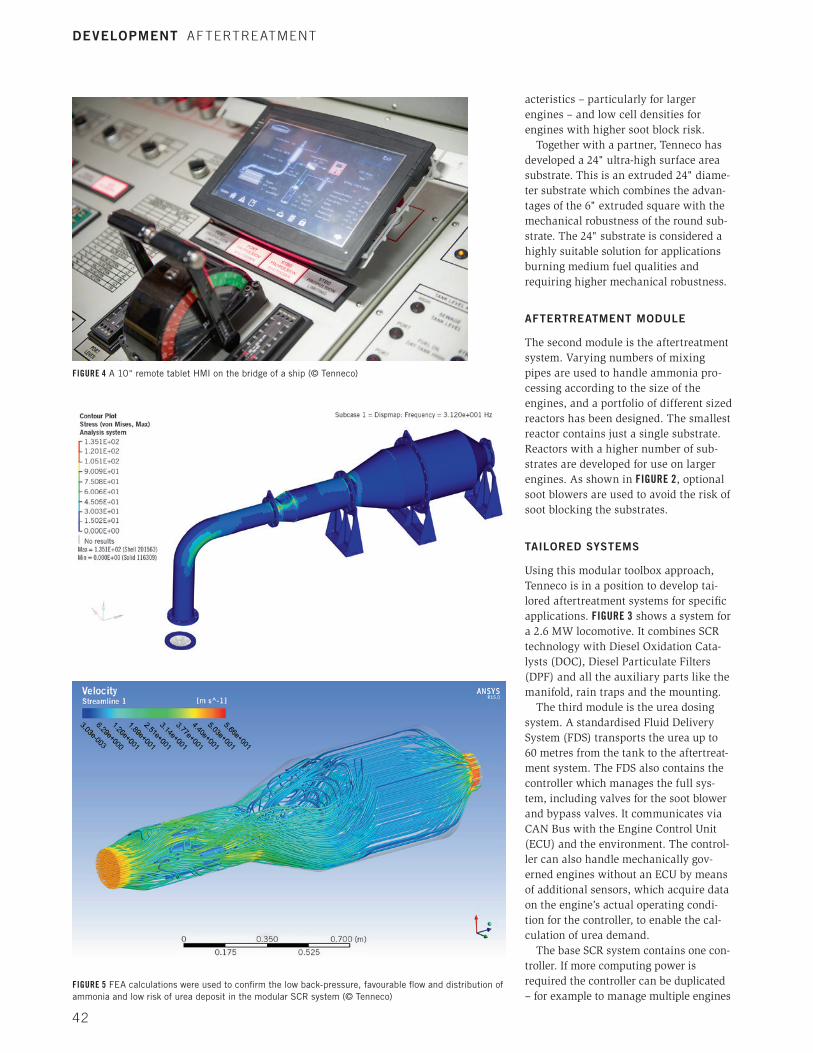
FIGURE 4 A 10" remote tablet HMI on the bridge of a ship (© Tenneco)
FIGURE 5 FEA calculations were used to confirm the low back-pressure, favourable flow and distribution of ammonia and low risk of urea deposit in the modular SCR system (© Tenneco)
DEVELOPMENT AFTERTREATMENT
42

with one FDS, or if more input/output sig-nals (I/Os) are needed to manage more than three urea injection points. In this case the first controller acts as the master controller and up to two additional slave controllers provide the required addi-tional computing capacity and I/Os.
The system’s Human Machine Inter-faces (HMI) permits access to diagnostic functions and helps to monitor and con-trol the system. All functionalities can be shared with higher systems via a CAN interface. Alternatively, a box-mounted 4" touch display or a 10" remote tablet, shown on the bridge of a ship in FIGURE 4, allows control and mon-itoring of the system.
AIRLESS DOSING
The dosing and atomisation of the urea into the aftertreatment system is done by airless injectors. The airless injector pro-vides high dosing accuracy with good spray performance while eliminating the capital and maintenance cost of com-pressed air systems. Up to three injectors can be mounted on one common rail if required. Multiple common rail modules can be connected to allow a larger num-ber of injectors.
SYSTEM DEVELOPMENT
Stable and robust processes are neces-sary to ensure the proper development of new products. The development of Ten-neco’s Large Engine SCR system fol-lowed Tenneco’s New Technology Imple-mentation Process (NTI). NTI guides development through different phases with clearly defined tasks and delivera-bles. At the end of each phase, a gate review takes place to confirm that the programme has reached the required level to move to the next phase.
In the first two phases, the concept is evaluated and the technical targets are specified. The views of the customer are of critical importance in the target defini-tion. Engine manufacturers, naval archi-tects, shipyards, and classification socie-ties all provided valuable input. In addi-tion to benchmarking activities, real world measurements of operating load were car-ried out. The exhaust system of a ship with a 3 MW propulsion engine was equipped with sensors. On a trip during heavy weather conditions on the Yellow Sea in China, mechanical load data was
collected. The product objectives were established at the end of this phase.
The concept was proven in the next phase with extensive use of CAE tools. Linear Finite Element Analysis (FEA) proved the durability of components
under engine vibration and low frequency loads. Non-linear FEA was used to verify thermo-mechanical durability of compo-nents. As exemplified in FIGURE 5, Compu-tational Fluid Dynamics (CFD) calcula-tions ensured low back-pressure, good
500
1000
1500
2000
2500
3000
3500
4000
4500
5000
800 900 1000 1100 1200 1300 1400 1500
Torq
ue [
Nm
]
Engine speed [rpm]
NOx conversion and ammonia slip
D
2 ppm 95 %
E3 Cycle
D2 Cycle
94 % 2 ppm
95 % 1 ppm
81 % 10 ppm
89 % 2 ppm
96 % 8 ppm
92 % 10 ppm
88 % 1 ppm
FIGURE 6 Example of the emissions performance for first modular SCR prototypes (© Tenneco)
DEVELOPMENT AFTERTREATMENT
Special Edition MTZ I September 2015 43
crank angle [°CA]
rail
pres
sure
[bar
]
flow and ammonia distribution, and low urea deposit risk. The system was opti-mised virtually using CAE methods before the prototype build.
CONCEPT DEMONSTRATION
Concept demonstration started with component testing. All major compo-nents were functionally tested. CAE tools
were used extensively to confirm and improve the SCR system concept, FEA was used for mechanical and thermo-mechanical durability and CFD to con-firm low back-pressure, good flow and ammonia distribution and low risk of urea deposition. An important compo-nent is the injector which is a derivative of Tenneco’s proven truck and off-road injector, modified for higher urea dosing
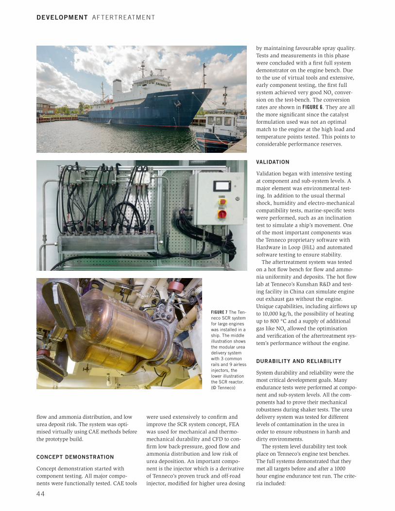
FIGURE 7 The Ten-neco SCR system for large engines was installed in a ship. The middle illustration shows the modular urea delivery system with 3 common rails and 9 airless injectors, the lower illustration the SCR reactor. (© Tenneco)
by maintaining favourable spray quality. Tests and measurements in this phase were concluded with a first full system demonstrator on the engine bench. Due to the use of virtual tools and extensive, early component testing, the first full system achieved very good NOx conver-sion on the test-bench. The conversion rates are shown in FIGURE 6. They are all the more significant since the catalyst formulation used was not an optimal match to the engine at the high load and temperature points tested. This points to considerable performance reserves.
VALIDATION
Validation began with intensive testing at component and sub-system levels. A major element was environmental test-ing. In addition to the usual thermal shock, humidity and electro-mechanical compatibility tests, marine-specific tests were performed, such as an inclination test to simulate a ship’s movement. One of the most important components was the Tenneco proprietary software with Hardware in Loop (HiL) and automated software testing to ensure stability.
The aftertreatment system was tested on a hot flow bench for flow and ammo-nia uniformity and deposits. The hot flow lab at Tenneco’s Kunshan R&D and test-ing facility in China can simulate engine out exhaust gas without the engine. Unique capabilities, including airflows up to 10,000 kg/h, the possibility of heating up to 800 °C and a supply of additional gas like NOx allowed the optimisation and verification of the aftertreatment sys-tem’s performance without the engine.
DURABILITY AND RELIABILITY
System durability and reliability were the most critical development goals. Many endurance tests were performed at compo-nent and sub-system levels. All the com-ponents had to prove their mechanical robustness during shaker tests. The urea delivery system was tested for different levels of contamination in the urea in order to ensure robustness in harsh and dirty environments.
The system level durability test took place on Tenneco’s engine test benches. The full systems demonstrated that they met all targets before and after a 1000 hour engine endurance test run. The crite-ria included:
DEVELOPMENT AFTERTREATMENT
44

– robust NOx abatement performance above a target of 75 %
– ammonia slip below a target of 10 ppm
– no urea deposit formation – no significant redunction in NOx con version (catalyst deterioration less than 3 %).
CUSTOMER AND FLEET TESTING
Several engine manufacturers have per-formed tests with Tenneco’s modular SCR system. One of the most recent was an 8 MW system which achieved IMO Tier III compliance on the customer’s test bench.
The final validation step is fleet test-ing. The first installation aboard a ship was on a vessel in the North American Great Lakes. The new aftertreatment sys-tem replaced the original exhaust line and was fitted into the engine room without major modifications.
By using the new SCR system, an IMO Tier 0 engine, built in 1984, was able to fulfil the IMO Tier III limits. As shown in FIGURE 7, a second system was installed
on an ocean-going vessel in the Gulf of Mexico. Here also, the test proved the system’s emissions reduction perfor-mance, achieving EPA Tier 4 standards. This installation was classified by the American Bureau of Shipping (ABS). Further installations aboard ships are ongoing.
SUMMARY AND OUTLOOK
Emissions legislation is constantly increasing demand for emissions control products for engines with outputs above 560 kW. By leveraging its expertise in emissions control and exhaust aftertreat-ment technologies, Tenneco has extended its portfolio of proven SCR technologies into this segment of the engine market.
Due to the diversity of technical requi-rements in the large engine market (dis-placements, power outputs, available installation space, retrofit applications) Tenneco’s global development team has implemented a modular approach. A toolbox of modules has been developed, from which a wide range of SCR systems can be precisely configured by Tenneco’s
application engineers to serve a given application.
A very stringent, proven development process was employed to guide the team through a series of product development gateways. Significant experience with simi-lar products for smaller engines, extensive use of CAE tools and in-house validation capabilities enabled a target-oriented devel-opment approach on a precise timescale.
In the meantime Tenneco SCR systems have proven their functionality and robustness both on the test-bench and in the field aboard seagoing and inland waterway vessels. The Tenneco urea delivery and aftertreatment systems are already certified by the ABS Classification Society and classification by DNV-GL and CCS are currently underway.
Increasingly stringent emissions legislation will continue to drive the development of emissions controls sys-tems for large engines and on the diesel side Tenneco intends to respond with fur-ther optimisation of its SCR system, including new modules to cover a maxi-mum of applications on both high and medium speed engines.
DEVELOPMENT AFTERTREATMENT
Special Edition MTZ I September 2015 45