modular ductwork specialists - norduct...
TRANSCRIPT

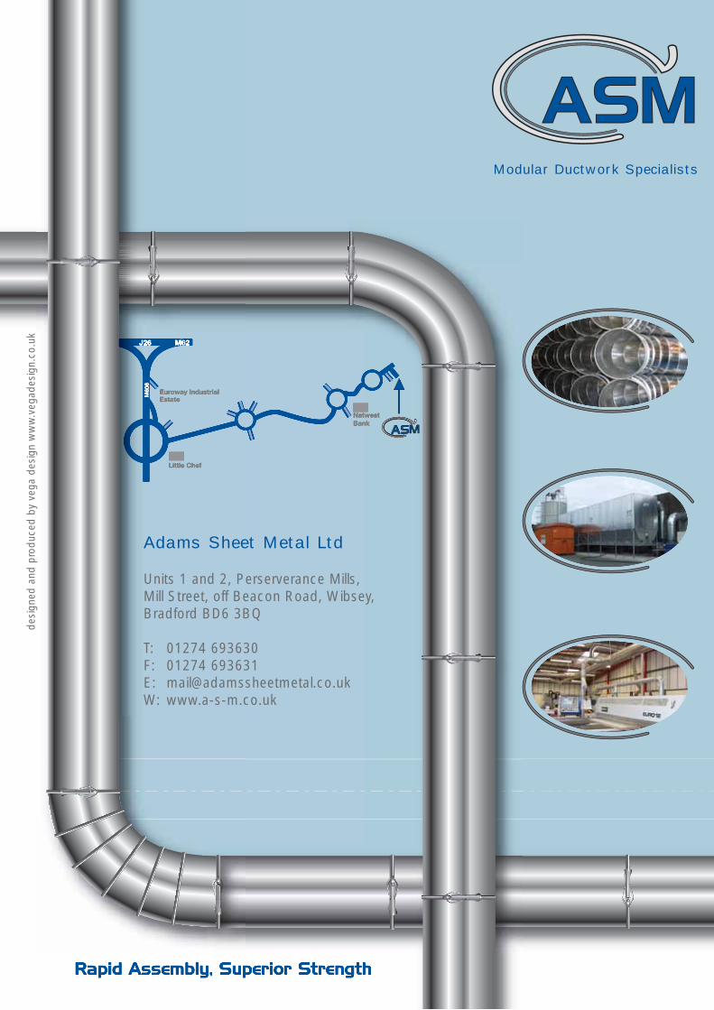
Rapid Assembly, Superior Strength
Modular Ductwork Specialists

Freephone: 0800 085 5616
2MODULAR DUCTWORK SPECIALISTS
ASM Ltd is the UK’s only complete manufacturer of quick assembly clippedducting and our products are in use in a wide variety of applications all over theworld. Our investment in product development, state-of-the-art manufacturingfacilities and highly experienced staff allows us to respond to even the mostdemanding ducting projects rapidly and effectively.
Design
All of our ducting is manufactured with a unique rolled edge formed directly ontothe end of the duct. This makes our ducting far stronger, so that it is easier andfaster to connect, dramatically reducing installation time. Less supports arerequired and complex designs can be assembled very rapidly.
Manufacturing
Our automated CNC roll forming and welding line ensures all ductwork is leakfree, unlike lock-form or spiral duct which badly leaks and allows debrisharbours and snag opportunities. In addition, our CNC plasma cutting systemensures production of accurate components to the most stringent sheetmetal tolerances. It guarantees that special components, such as tapers,rectangular to round and many non-standard or highly complicated shapes,can be cut with lightning speed and total accuracy.
We also operate one of only two machines in the world which canmanufacture clips for our full range of ducting, thus ensuring that the wholemanufacturing process is controlled to our exacting quality standards.
Materials
We can supply ducting from 100mm to 1000mm diameter in galvanised, galvaneal (for paint and powder coating), stainlesssteel (304 and 316) and aluminium.
One-Stop Duct Shop
ASM Ltd is best-known for its straight ducts and bends, but we can produce a wide range of ducting parts andaccessories. Quick Assembly duct comes in diameters ranging from 100mm-500mm and we make all the branches,adapters and transitions. ASM Ltd can also produce custom parts such as machine hoods, fixing brackets, lightfabrications, etc. We also offer flanged ducting up to 1000mm in diameter as standard.
Whether your application calls for light or heavy gauge duct, moderate to severe process criteria, we have the right productfor the job.
Our experienced staff can review your requirements with you, or justsend your specifications and we will provide a design solution.

Rapid Assembly, Superior Strength
3CONTENTS
Modular Ductwork Specialists p2
Instructions p4
Products p5StraightsSegmented BendPressed BendQ.A. Slip
Clips p6Taper Branch Taper
Y Piece p7Branch PlateBoot Shoe Branch
Sputnik Type 1 and 2 p8Custom ManifoldsRectangular to Round
Automatic Damper p9Blast Gate DamperElliptical Damper
Closed Sweep Up p10Q.A. Jet HatterSilencer
Split Strap p11FlangesNipple
End Cap p12Floor PlateDiverter Valve
Polyurethane Ducting p13
Filter Spares p14Flanged StraightsFlanged Bends
Flanged Taper Branch p15Flanged Taper
L.E.V. Testing and System Design p16
Technical Information p17
Area and Volume Charts p20
Installation Tips p22
Conditions of Sale p23

Email: [email protected]
4
The Q.A. Clip System is so easy to install that it eliminates time consuming and costly procedures. There is no longer anyneed to use rivets or screws, just the quick release clip with integral seal.
● Easy to install ● No rivets or screws required● Quick release clip with integral seal ● Smooth internal finish● Easily adapted to existing systems ● Available in galvanised and stainless steel
All Q.A. Clipped duct systems are equipped with a rolled collar at both ends that serves as a clipping edge for the Q.A. clip.
This results in tight joints and combined with the smooth internal finish producing low transitional resistance, ensures thatthe Q.A. System is ideal for pneumatic transport of material. Ease of assembly and re-assembly makes this the ideal systemwhen re-siteing machinery, thus cutting possible costly down-time.
Instructions for installing slip joint
Step 1
Requirements for using an adjustable slip are a duct length lessthan the standard 1250mm section of duct.
Step 3
Be sure that the cut section of the duct is placed into the linewith the direction of air flow.
Step 5
Finish connection using the adjustable slip assembly.
Step 2
Cut non-standard length from standard 1250mmsection of duct.
Step 4
Adjust the assembly to the proper length required forthe space to be filled.
INSTRUCTIONS
AIR FLOW
LESS THAN1250 MMAIR FLOW
NON-STANDARD LENGTH = X
REQUIRES CUTTING STAND. LENGTHCUT LENGTH = X-100mm
FROM STANDARD SECTION OF DUCT
STANDARD DUCT LENGTH
AIR FLOW
DUCT CUT TO LENGTH (100mm) STEP 2
RUBBER O-RING
Q.A. ADJUSTABLE SLIP300mm LONG WITH ROLLEDENDS ON BOTH ENDS
ADJUSTABLE SLIP
Q.A. CLIP
DUCT CUT TO LENGTH
CLIP INCORPORATES RUBBERO-RING AND ROLLED ENDFROM THE ADJUSTABLE SLIPFOR SEALING PURPOSES
AIR FLOW
“A”“A”
DUCT CUTTO LENGTH
RUBBER O-RING
ADJUSTABLE SLIP ASSEMBLY
ADJUSTABLE SLIP
AIR FLOW
RUBBER O-RINGADJUSTABLE SLIP
Q.A. CLIP
DUCT CUT TO LENGTH

Rapid Assembly, Superior Strength
5
Dia Sheet Nominal kgThickness Length
100 0.7mm 1250mm 2.00125 0.7mm 1250mm 2.50140 0.7mm 1250mm 2.75160 0.7mm 1250mm 3.75180 0.7mm 1250mm 4.12200 0.7mm 1250mm 5.25250 0.7mm 1250mm 5.60315 0.7mm 1250mm 6.90350 0.7mm 1250mm 7.50400 0.7mm 1250mm 11.00450 0.7mm 1250mm 12.50500 0.7mm 1250mm 14.00
Dia Sheet Nominal kgThickness Length
100 0.7mm 300mm 0.51125 0.7mm 300mm 0.63140 0.7mm 300mm 0.69160 0.7mm 300mm 0.81180 0.7mm 300mm 1.09200 0.7mm 300mm 1.18250 0.7mm 300mm 1.48315 0.7mm 300mm 1.87350 0.7mm 300mm 2.12400 0.7mm 300mm 2.84450 0.7mm 300mm 3.21500 0.7mm 300mm 3.57
Dia CLR Style DEG DEG DEG DEG TANGENTRadius A
x D
100 1.0 P 90 60 45 30 40125 1.0 P 90 60 45 30 40140 1.0 P 90 60 45 30 40160 1.0 P 90 60 45 30 40180 1.0 P 90 60 45 30 40200 1.5 S 90 60 45 30 80250 1.5 S 90 60 45 30 80315 1.5 S 90 60 45 30 80350 1.5 S 90 60 45 30 80400 1.5 S 90 60 45 30 80450 1.5 S 90 60 45 30 80500 1.5 S 90 60 45 30 80
P = Press S = Segmented CLR = Centreline Radius, Other Radii available on request
Dia
L
L
Dia
SEGMENTED BEND
Dia
TANGENTA
C.L.R.
PRESSED BENDA TANGENT
Dia
C.L.R.
PRODUCTS
STRAIGHTS● Fully welded construction● Ex-Stock 100mm to 500mm● Smooth internal finish● Rolled edge for ease of assembly● Flanged upon request
Q.A. SLIP● Fully welded construction● Smooth internal finish● Supplied with “0” ring
Freephone: 0800 085 5616
Dia “B” mm kg
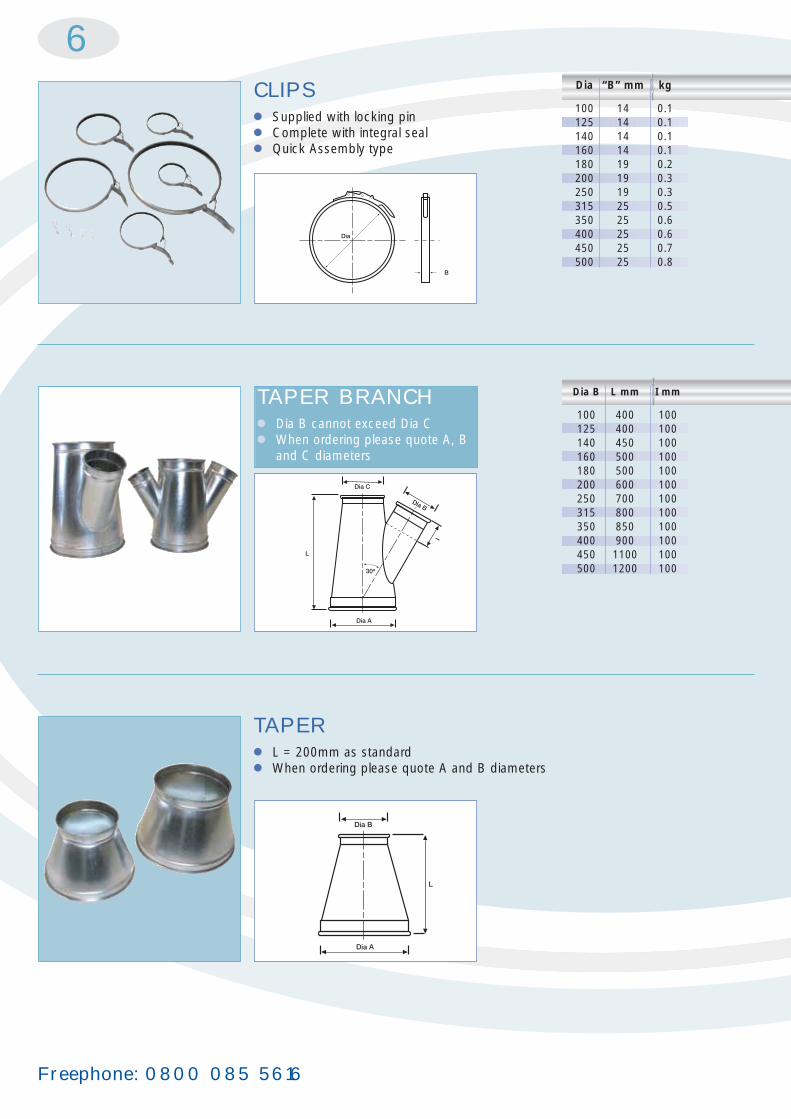
100 14 0.1125 14 0.1140 14 0.1160 14 0.1180 19 0.2200 19 0.3250 19 0.3315 25 0.5350 25 0.6400 25 0.6450 25 0.7500 25 0.8
Dia B L mm I mm
100 400 100125 400 100140 450 100160 500 100180 500 100200 600 100250 700 100315 800 100350 850 100400 900 100450 1100 100500 1200 100
6CLIPS● Supplied with locking pin● Complete with integral seal● Quick Assembly type
Dia
B
Dia A
30o
L
Dia C
I
Dia B
TAPER ● L = 200mm as standard● When ordering please quote A and B diameters
Dia A
L
Dia B
TAPER BRANCH● Dia B cannot exceed Dia C● When ordering please quote A, B
and C diameters

Rapid Assembly, Superior Strength
7
Dia L mm I mm
100 400 100125 500 100140 530 100160 570 100180 570 100200 650 100250 750 100315 880 100350 950 100400 1050 100450 1150 100500 1370 100
Y PIECE ● B and C diameters cannot exceed A● When ordering please quote A, B and
C diameters
Dia A
Dia BDia C
BRANCH PLATE● Dia A cannot exceed Dia B● When ordering please quote A and B diameters
Dia A
Dia B
I
L
30o
BOOT SHOE BRANCH
● Dia B cannot exceed Dia C● When ordering, please quote A, B and C
diameters
Dia B
L
Dia CDia A
Email: [email protected]
8
50
L
Bmm
Amm
Dia B
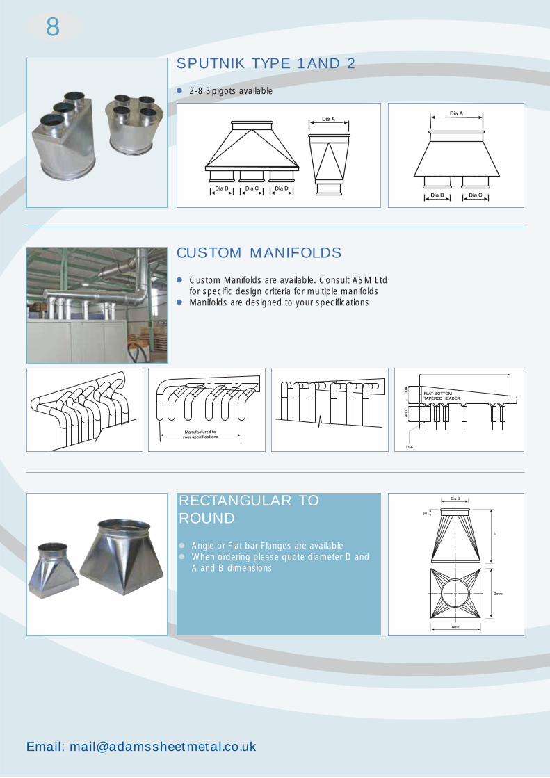
SPUTNIK TYPE 1 AND 2
● 2-8 Spigots available
Dia B Dia C Dia D
Dia A
Dia B
Dia A
Dia C
Manufactured toyour specifications
FLAT BOTTOMTAPERED HEADER
DIA
QA
400
CUSTOM MANIFOLDS
● Custom Manifolds are available. Consult ASM Ltd for specific design criteria for multiple manifolds
● Manifolds are designed to your specifications
RECTANGULAR TOROUND
● Angle or Flat bar Flanges are available● When ordering please quote diameter D and
A and B dimensions

Rapid Assembly, Superior Strength
9
BLAST GATE DAMPER
● Cast Aluminium Body● Steel Blade
C
ED D
B
A
ELLIPTICAL DAMPER
● 2mm fully welded construction● 1 x coat primer
1 x topcoat gloss
Dia A B C D Emm mm mm mm mm
100 100 125 134 33 80125 125 150 165 45 87140 140 165 178 45 135160 160 190 203 45 135180 180 200 216 45 135200 200 228 240 47 135250 250 285 303 50 160
AUTOMATIC DAMPER
GeneralThe pneumatic damper is a circularcompressed air powered automatic slidedamper for rapid and tight closure. Since thedamper is opened and closed automatically,extraction is always focused on theconnections, extraction points or machinescurrently in operation. This maximizesextraction power, with lower energyconsumption as a bonus. You will have
cleaner end-products and machinery, cleaner floors plus improved health and a betterworking environment.
DesignIn its standard form, the damper is made of zinc-platedsteel plate but it can also be supplied in a stainless steelimplementation. Installation can be carried out in anoptional position.
The automatic damper is opened and closed using one ortwo compressed air cylinders. The cylinder is operatedfrom a solenoid valve connected to the work process orfrom an operating switch.
Diam
A
D
C
E
B
Dia A B C D E WEIGHTkg
100 225 180 265 105 290 3.50125 225 205 315 105 340 4.00140 225 230 365 105 390 4.50160 225 240 385 105 410 5.20180 225 280 465 105 490 6.20200 225 280 465 105 490 6.40250 265 370 565 130 585 13.50315 265 435 695 130 730 21.00350 265 470 765 130 800 25.00400 265 520 865 130 905 29.00
DIAMETERS LARGER THAN 180MMARE FITTED WITH 2 CYLINDERS

Freephone: 0800 085 5616
10CLOSED SWEEP UP
● Available in diameters 100 - 180
310
2.0THK
Dia
310
250
dia DIA Height kg(d) (D) (H)
160 240 375 4200 320 475 6250 400 575 8315 480 675 10350 560 775 13400 640 875 16450 720 975 20500 800 1075 25560 880 1175 28630 960 1275 36710 1120 1475 49800 1280 1675 68900 1440 1875 100
1000 1600 2075 150
Q.A. JET HATTER
dia d
H
DIA D
WALL THICKNESS
Dia A
L
INS
ULA
TIO
N
SILENCER
● Reduces noise on fan discharge● Various wall thicknesses● Made to any specification

Rapid Assembly, Superior Strength
11SPLIT STRAP
● Manufactured in 30 x 3 galvanised sheet steel 100mm dia-500mm dia and 40 x 5 F/Bar 560 dia-1000 dia
Dia
Dia I.D P.C.D O.D No.of a x b Weightmm mm kg holes mm kg
100 103 127 143 4 5 x 20 0.30125 128 157 178 4 5 x 25 0.45140 143 172 193 6 5 x 25 0.50160 163 192 213 6 5 x 25 0.55180 183 212 233 6 5 x 25 0.65200 203 232 253 6 5 x 25 0.70250 253 289 313 6 5 x 30 1.05315 317 349 377 8 5 x 30 1.25350 353 387 413 8 5 x 30 1.40400 404 438 464 12 5 x 30 1.55450 454 488 514 12 5 x 30 1.75500 504 538 564 12 5 x 30 1.95560 564 600 625 12 5 x 30 2.15630 634 670 695 16 5 x 30 2.40710 714 750 775 16 5 x 30 2.70800 804 848 884 16 5 x 40 4.10900 904 948 984 16 5 x 40 4.60
1000 1004 1049 1085 16 5 x 40 5.10
Dia Length kg
100 58 0.1125 58 0.2140 58 0.2160 58 0.3180 58 0.3200 58 0.3250 58 0.4315 58 0.5350 58 0.5400 58 0.7450 58 0.8500 58 0.9
FLANGES
● Hot dipped galvanised after manufacture
O.D. P.C.D. I.D.
A
B
NIPPLE
Dia
L

Email: [email protected]
212
Dia A
Dia B
3.0
Dia Length kg
100 54 0.4125 54 0.4140 54 0.4160 54 0.5180 49 0.9200 49 0.8250 45 0.8315 42 1.0350 42 1.0400 42 1.4450 42 1.4500 42 1.8
END CAP
Dia A
L
DIVERTER VALVE
● Highly efficient, economical method of diverting flow of material or air ● Manual or automatic operation available ● Constructed of heavy 3mm thick steel, with welded seams● Supplied with heavy-duty flange bearings and neoprene sealed blade
FLOOR PLATE
● For Dia B add 100mm onto Dia A

Rapid Assembly, Superior Strength
13Nominal Weight Min bend Max Max
Bore radius to working workingcentra- pressure vacuum
line
38 250 40 60 388145 324 50 60 375151 316 55 60 369863 500 60 60 329276 636 80 60 306282 689 85 60 290989 748 90 60 2756
102 860 100 55 2450115 1002 110 55 2220127 1040 120 55 1914140 1234 130 55 1684152 1294 140 50 1531160 1354 145 50 1378178 1556 180 50 1148203 1784 205 50 919229 2012 215 40 766254 2232 220 40 689305 2680 230 40 536
POLYURETHANEDUCTING
Properties:A highly flexible light duty polyurethaneducting made from 1 ply polyurethanematerial and supported by a coated semi-spring steel helix.
Applications:Ideally suited for extraction of abrasiveproducts such as wood waste, metalfilings and granules.
Flexible:Excellent flexibility and a high flex life.
Durable:Excellent internal and external abrasion resistance.
Standard Lengths:10 metres: 38 - 305mm bore
Colour:Translucent/blue wire
Temperature Range:-30oC to +110oC ambient

Freephone: 0800 085 5616
14
Dia Sheet Nominal WeightThickness Length kg
560 0.9mm 2500mm 31.00 630 0.9mm 2500mm 34.00 710 0.9mm 2500mm 40.00 800 0.9mm 2500mm 45.00 900 0.9mm 2500mm 50.00
FLANGED STRAIGHTS
● Fully welded construction● Smooth internal finish● Flat bar flange● Spinning flanges for ease
of assembly
Dia
L
FLANGED BENDS
Dia
TANGENTA
C.L.R.
Dia CLR Rad. Style DEG DEG DEG DEG TANGENT TANGENTx D
100 1.0 P 90 60 45 30 40 40125 1.0 P 90 60 45 30 40 40140 1.0 P 90 60 45 30 40 40160 1.0 P 90 60 45 30 40 40180 1.0 P 90 60 45 30 40 40200 1.5 S 90 60 45 30 80 80250 1.5 S 90 60 45 30 80 80315 1.5 S 90 60 45 30 80 80350 1.5 S 90 60 45 30 80 80400 1.5 S 90 60 45 30 80 80450 1.5 S 90 60 45 30 80 80500 1.5 S 90 60 45 30 80 80560 1.5 S 90 60 45 30 80 80630 1.5 S 90 60 45 30 80 80710 1.5 S 90 60 45 30 80 80800 1.5 S 90 60 45 30 80 80900 1.5 S 90 60 45 30 80 80
1000 1.5 S 90 60 45 30 80 80P = Press S = Segmented CLR = Centreline Radius,
Other Radii available on request
FILTER SPARES
● Full range of filter spares carried Ex-Stock
● Complete maintenance contracts available

Rapid Assembly, Superior Strength
315Dia B L mm I mm
100 400 100125 400 100140 450 100160 500 100180 500 100200 600 100250 700 100315 800 100350 850 100400 900 100450 1100 100500 1200 100560 1300 100630 1450 100710 1600 100800 1800 100900 2000 100
1000 2300 100
FLANGED TAPERBRANCH
● Dia B cannot exceed Dia C● When ordering please quote A
and C diameters
Dia A
30o
L
Dia C
I
Dia B
FLANGED TAPER
● L = 200m as standard● When ordering please quote A
and B diameters
L
Dia B
Dia A
Email: [email protected]
16
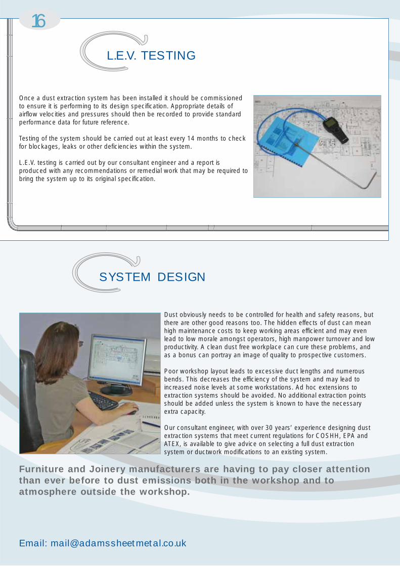
Once a dust extraction system has been installed it should be commissionedto ensure it is performing to its design specification. Appropriate details ofairflow velocities and pressures should then be recorded to provide standardperformance data for future reference.
Testing of the system should be carried out at least every 14 months to checkfor blockages, leaks or other deficiencies within the system.
L.E.V. testing is carried out by our consultant engineer and a report isproduced with any recommendations or remedial work that may be required tobring the system up to its original specification.
L.E.V. TESTING
Dust obviously needs to be controlled for health and safety reasons, butthere are other good reasons too. The hidden effects of dust can meanhigh maintenance costs to keep working areas efficient and may evenlead to low morale amongst operators, high manpower turnover and lowproductivity. A clean dust free workplace can cure these problems, andas a bonus can portray an image of quality to prospective customers.
Poor workshop layout leads to excessive duct lengths and numerousbends. This decreases the efficiency of the system and may lead toincreased noise levels at some workstations. Ad hoc extensions toextraction systems should be avoided. No additional extraction pointsshould be added unless the system is known to have the necessaryextra capacity.
Our consultant engineer, with over 30 years’ experience designing dustextraction systems that meet current regulations for COSHH, EPA andATEX, is available to give advice on selecting a full dust extractionsystem or ductwork modifications to an existing system.
Furniture and Joinery manufacturers are having to pay closer attentionthan ever before to dust emissions both in the workshop and toatmosphere outside the workshop.
SYSTEM DESIGN

Rapid Assembly, Superior Strength
17
Adapting to an Existing System
There may be cases where you want to apply Q.A. Duct to an existing system. ASM makes adapters for this purpose.These can be provided in flanged to rolled edge style to pick existing flanged duct systems (please specify I/Dia, O/Dia,number and dia of holes and P.C.D.), or by plain end to rolled edge style to fit inside or outside existing or spiral wound duct.
Hints for Ordering
● Order one clip per Q.A. ProductDuct component: 1 duct = 1 clip, 2 bends = 2 clips
● Specify dimensional information to speed up process:
● Rolled Edge● Lipped Edge● Flanged
● Flexible Connection● I/Dia● O/Dia
● Specify end configuration required:
● Look for 60 degree bends to compliment 30 degree branch orders.
● Specify your needs (i.e. flange styles, hole patterns). Typical parts requiring flanges will be parts that connect to filters and fans.
Paint Used on Spot Welds
TEC-ALLOY, Aluminium metal coating # 1950.
Collapsibility Strength of Q.A. Ducting
Each size of ducting has been tested for strength against collapsing. The ducting was exposed to constant positive pressureand constant vacuum. Each duct was exposed to a maximum capacity of the test equipment of 40” WG of vacuum andpositive pressure. None of the duct showed any form of deformation during the test. Duct and fittings must be installed inaccordance with ASM’s standard specifications and normal good workmanship practices.
Leakage
All fit together ducting systems allow for some degree of leakage. Q.A. ducting is no exception and is not sold as an airtightsystem. In addition to standard PVC foam gasket, ASM offers special clip gasket material for high heat and enhancedsealing. Further, the applying of sealants to the individual rolled ends can enhance the tightness of the system. However, theQ.A. system is sold as a quick way of installing and modifying ductwork, while at the same time retaining the usability ofeach component. In short, Q.A. is meant to be able to be taken apart, re-assembled, stored or moved. Completelyeliminating the possibility for leakage jeopardises the inherent benefits of the duct. Standard Q.A. is designed to provide tightsealing and efficient airflow under negative pressures. To that end we are providing the following information for ductingsituations where fan sizing is of extreme importance.
● Taper Branches - A x B x C● Taper - A x B● ‘Y’ Piece - A x B x C
● Branch Plate - A x B● Boot Shoe Branch - A x B x C x L
TECHNICAL INFORMATION

Freephone: 0800 085 5616
218
Installing a Branch Plate
● Temporarily place the Branch Plate on the main duct in the required position, and while holding in place, mark the interior of the branch on the duct line where it is to be cut.
● Take down Branch Plate and drill a starter hole in the main duct along the line traced from the branch. Then using metal snips or a jigsaw, cut out metal piece that has been traced out. File or grind any sharp edges to ensure efficient flow.
● Now use an industrial strength silicone sealant to seal between Branch Plate and main duct.
● Use small sheet metal screws or pop rivets to secure Branch Plate to main trunk.
Painting Galvanised Components
Wash down all components with an industrial degreaser, ensuring that no oils or residues are left behind. Apply an epoxyprimer in a light coating. For final coat, apply an acrylic water base paint.
Sealant Used on Seams of Components
Scotch Seal 2084 metal sealant, 3m ID # 62-2084-2631-2.Ingredients: acetone, acrylonitrile, kaolin, phenolic resin, rosin ester Salicylic acid, aluminium pigment zinc oxide, amorphous silica.
Duct Specifications
Component Material
● Components constructed of galvanised steel sheets produced by the continuous galvanising process, which conforms to lock forming quality ASTM A-527, and commercial quality ASTM A-526. Galvanised sheeting is produced with the minimum of spangle.
● Components constructed of stainless steel will be 304 2B mill finish as standard, or 316 2B mill finish if specified.
The following data was obtained using standard components and was performed in accordance with the ‘HVAC AIR DUCTLEAKAGE TEST MANUAL’. The information gives the leakage rate per joint of duct at various pressures. To utilise the chart,count the number of clips (this equals the number of pieces) per rise and multiply by the number given beside thecorresponding diameter and under the applicable pressure. These numbers assume that the product is properly installed;free of dents in the joining ends and that the gasket is in place. Special gasket material and sealants will increase the sealing capabilities.
Leakage Rate in CFM per Q.A. Joint
Dia mm 3”WG 5”WG 7.5”WG 10”WG 15”WG 20”WG 25”WG 30”WG
100 0.20 0.25 0.30 0.30 0.35 0.50 0.60 0.80125 0.20 0.25 0.30 0.30 0.35 0.50 0.60 0.80140 0.20 0.25 0.30 0.30 0.35 0.50 0.60 0.80160 0.20 0.25 0.30 0.30 0.35 0.50 0.60 0.80180 0.20 0.25 0.30 0.30 0.35 0.50 0.60 0.80200 0.20 0.25 0.30 0.30 0.35 0.50 0.60 0.80250 0.20 0.25 0.30 0.30 0.35 0.50 0.60 0.80315 0.30 0.30 0.40 0.40 0.40 0.60 0.70 0.90350 0.30 0.30 0.50 0.70 0.80 0.80 0.90 1.10400 0.30 0.40 0.60 0.70 1.00 1.10 1.20 1.40450 0.40 0.40 0.70 0.80 1.10 1.30 1.50 1.70500 0.40 0.60 0.80 0.90 1.20 1.50 1.70 2.00

Rapid Assembly, Superior Strength
19Ductwork
● Rolled Edge - Material sheet blanks are 1250mm long and rolled with a fully welded longitudinal seam. The ends of the duct are then formed at each end, thus producing a rolled edge on both ends of the duct, and creating reinforcement every 1250mm.
● Flanged - Material sheet blanks are 2500mm long and rolled with a fully welded longitudinal seam. A flat bar flange is placed on the end of each duct, and is allowed to spin, thus making it easier to line up holes when installing. All rolled duct joints are secured by using a clip. Locking pins are installed to ensure that clips cannot be accidentally released once installed.
Duct should be supported as follows:
Supports should be installed to provide lateral stability to the entire ducting system. Each installation is unique and should be evaluated.
Velocity Requirements for Typical Materials
Rule of Thumb - Labour Guidelines
The following methods should be used for comparison and budgetary purposes only! By no means should they be used toconfirm a job installation.
Machine Connections
Quick Method = (total number of ports) x 3 hours Y, Y x 2 Ducting system total man hours.
Conveyed Material Velocity FPM Example
Gases, Smoke, 1000 - 2000 All Vapours, Gases andVapour SmokeFumes 2000 - 2500 WeldingVery Fine Light Dust 2500 - 3000 Cotton Lint, Litho
Powder, Wood FlourDry Dusts 3500 - 4000 Light Shavings, Rubber and Powders Dust, Soap DustIndustrial Dust 4000 - 4500 Wet Sawdust, Metal
Turnings, Wood BlocksHeavy or Moist 4500 + Moist Cement Dusts,
Quick Lime Dusts
● 100 Dia - 250 Dia on 7 metre centres. ● 315 Dia - 900 Dia on 5 metre centres.
● Machines with 3 or more ports = 3 hours per machine ● Machines with 1-2 ports = 2 hours per machine
● A + B = Man hours● Straight runs and trunk lines
● Rolled edge duct = 10 hours per 50 metres● Flanged duct = 15 man hours per 50 metres

Email: [email protected]
20
Circular Ductwork
Dia mm 2000FPM 2500FPM 3500FPM 4000FPM 4300FPM 4500FPM 5000FPM 5500FPM 6000FPM 6300FPM 6700FPM 6900FPM Area
CFM CFM CFM CFM CFM CFM CFM CFM CFM CFM CFM CFM SQ.FT
50 42 53 74 85 91 95 106 116 127 133 142 146 0.02160 61 76 107 122 131 137 152 167 183 192 204 210 0.03075 95 119 166 190 205 214 238 262 285 300 319 328 0.04880 95 119 166 190 205 214 238 298 285 300 319 328 0.05490 137 171 240 274 295 308 342 277 411 432 459 473 0.068
100 169 211 296 338 364 381 423 465 507 533 567 583 0.085125 264 330 462 528 568 595 661 727 793 832 885 912 0.132140 331 414 580 663 713 746 829 912 994 1044 1110 1144 0.166160 433 561 758 866 931 974 1085 1191 1299 1364 1450 1494 0.216180 548 685 959 1096 1178 1233 1370 1507 1644 1726 1836 1890 0.274200 676 846 1184 1353 1454 1522 1691 1860 2029 2131 2266 2334 0.338250 1057 1321 1850 2114 2273 2378 2642 2907 3171 3330 3541 3647 0.528315 1678 2098 2937 3356 3608 3776 4195 4615 5034 5286 5622 5789 0.839350 2072 2590 3625 4143 4454 4661 5179 4697 6215 6526 6940 7147 1.036400 2706 3382 4735 5412 5815 6088 6765 7441 8118 8524 9065 9335 1.353450 3425 4281 5993 6849 7363 7705 8562 9418 10274 10788 11473 11815 1.712500 4228 5285 7399 8456 9090 9513 10570 11627 12684 13318 14164 14586 2.114560 5304 6629 9281 10607 11403 11933 13259 14585 15911 16706 17767 18297 2.652630 6712 8390 11746 13425 14431 15103 16781 18459 20137 21144 22486 23157 3.356710 8525 10657 14919 17050 18329 19182 21313 23444 25576 26854 28559 29412 4.263800 10824 13529 18941 21647 23271 24353 27059 29765 32471 34094 36259 37341 5.412900 13699 17123 23972 27397 29452 30822 34246 37671 41096 43150 45890 47260 6.849
1000 16912 21140 29596 33824 36360 38051 42279 46507 50735 53272 56654 58346 8.456
Square Ductwork
600 7751 9688 13564 15502 16664 17439 19377 21315 23252 24415 25965 26740 3.875800 13779 17224 24114 27558 29625 31003 34448 37893 41337 43404 46160 47538 6.890
1000 21530 26912 37677 43060 46289 48442 53825 59207 64590 67819 72125 74278 10.765
Area and Volume Chart (cubic feet per minute (CFM))
AREA AND VOLUME CHARTS

Rapid Assembly, Superior Strength
21
Circular Ductwork
Dia mm 10 M/S 15 M/S 18 M/S 20 M/S 22 M/S 23 M/S 25 M/S 28 M/S 30 M/S 32 M/S 34 M/S 35 M/S Area
CU.M/HR CU.M/HR CU.M/HR CU.M/HR CU.M/HR CU.M/HR CU.M/HR CU.M/HR CU.M/HR CU.M/HR CU.M/HR CU.M/HR SQ.M
50 71 106 127 141 156 163 177 198 212 226 240 247 0.00260 102 153 183 204 224 234 255 285 305 326 346 356 0.00375 159 239 286 318 350 366 398 445 477 509 541 557 0.00480 181 271 326 362 398 416 452 507 543 579 615 633 0.00590 229 344 412 458 504 527 573 641 687 733 779 802 0.006100 283 424 509 566 622 650 707 792 848 905 961 990 0.008125 422 663 795 884 972 1016 1105 1237 1326 1414 1502 1546 0.012140 554 831 998 1108 1219 1275 1386 1552 1663 1774 1884 1940 0.015160 724 1086 1303 1448 1593 1665 1810 2027 2172 2317 2461 2534 0.020180 916 1374 1649 1832 2016 2107 2291 2565 2749 2932 3115 3207 0.025200 1131 1697 2036 2262 2488 2602 2828 3167 3393 3620 3846 3959 0.031250 1767 2651 3181 3535 3888 4065 4418 4949 5302 5656 6009 6186 0.049315 2806 4209 5051 5612 6173 6454 7015 7856 8418 8979 9540 9821 0.078350 3464 5196 6235 6928 7621 7967 8660 9699 10392 11085 11778 12124 0.096400 4524 6787 8144 9049 9954 10406 11311 12669 13573 11447 15383 15836 0.126450 5726 8589 10307 11453 12598 13170 14316 16034 17179 18324 19469 20042 0.159500 7070 10604 12725 14139 15553 16260 17674 19795 21209 22622 24036 24743 0.196560 8868 13302 15962 17736 19510 20396 21170 24830 26604 28378 30151 31038 0.246630 11224 16835 20202 22447 24692 25814 28059 31426 33671 35915 38160 39282 0.312710 14255 21382 25659 28510 31361 32786 35637 39914 42765 45616 48467 49892 0.396800 18098 27147 32576 36196 39815 41625 45245 50674 54294 57913 61533 63343 0.503900 22905 34358 41229 45810 50391 52682 57263 64135 68716 73297 77878 80168 0.6361000 28278 42417 50900 56556 62212 65039 70695 79178 84834 90490 96145 98973 0.786
Square Ductwork
600 10180 15270 18324 20360 22396 23414 25450 28504 30540 32576 34612 35630 0.283800 18098 27147 32576 36196 39815 41625 45245 50674 54294 57913 61533 63343 0.5031000 28278 42417 50900 56556 62212 65039 70695 79178 84834 90490 96145 98973 0.786
Area and Volume Chart (cubic metres per hour (CU.M/HR))

Freephone: 0800 085 5616
22
Step 1
Connect all 30o Branchpieces and 60o elbows toproduce a required 90o
angle. Lay out branch andelbow assemblies on thefloor in line with machineentry points as shown.
60o ELBOW
BRANCH @ 30o
Step 3
Carefully raise main or sub-main to required centreline height above floor usingpreferred ASM hangingmaterial.
STANDARDHANGER
CABLEHANGER
TR HANGER
Step 2
Connect the branches toducting sections of thecorrect length and diameter.Adjustment to length onduct sections is achieved byusing ASM slip jointassembly instructions onpage 4.
SLIP JOINTS
CUT TO LENGTHPIECES OF DUCT
Step 4
Extend branch arms tomachines using correctlength and diameter duct.Adjustment to length of ductsections is achieved byusing ASM slip jointassembly instructions onpage 4. Fit another 90o
elbow on end of eachhorizontal run.
SLIP JOINTS
SLIP JOINTSSLIP JOINTS
Step 6
Connect main or sub-mainto filter, fan or desiredmachinery with requiredstandard or custom fittingmanufactured by ASM, orcontinue with next section ofsystem.
AIR FLOW TO FAN
Step 5
Install vertical risers from machines to horizontal runs usingyour preferred method of connection.
SLIP JOINT
ADAPTER WITHRAW END
SLIP JOINT
ADAPTER WITHRAW END
HARD DUCTTO SIDE CONNECTION
HARD DUCTTO TOP CONNECTION
90o ELBOW
SLIP JOINT
FLEX HOSE
ADAPTER WITHRAW END
FLEX HOSETO TOP CONNECTION
INSTALLATION TIPS
Rapid Assembly, Superior Strength
23
1. These conditions shall be incorporated in and govern every Quotation, offer, acceptance and offer for sale of goods by A.S.M. Ltd, (hereafter called the ‘Seller’) and all other conditions, warranties and representations whether made orally or in writing whether expressed or implied are herby expressly excluded.
2. The Quotation given by the Seller shall be subject to the written confirmation of acceptance upon receipt of the purchase order and no contract shall be concluded until such confirmation is given or the purchase order has otherwise been accepted by the Seller.
3. There shall be no variation, amendment or alteration or waiver to or in respect of the Quotation to these conditions or the Contract unless agreed in writing by the Seller.
4. The Price for the goods shall be as specified or referred to in the Quotation and unless otherwise stated, the Price shall be exclusive of Value Added Tax, of all insurance, packing, loading, unloading and delivery costs and charges and all customs duties, import/export charges, levies, taxes and other similar charges.
5. Notwithstanding anything contained herein to the contrary, the Price quoted or referred to in the Quotation may be varied by the Seller after any contract has beenentered into and the Seller as a result of any increase between the date of Quotation and Delivery where such increase is due to a change in market conditions beyond the reasonable control of the Seller. The term ‘Market Conditions’ shall include but not be limited to increases in the cost of, or charges of, labour, raw or other materials, transport or handling charges, the imposition amendment or alteration in any statute, order, regulation or bye law in respect of any duty tax impost or as a result of the imposition or change in any requirement for export or import licenses.
6. Payment shall be made by the Purchaser on the due date, namely the date of delivery unless otherwise specified or agreed between the parties.
7. If the Purchaser shall fail to pay the Seller by date due for payment the Seller may either suspend all further deliveries until payment is made in full or cancel the orderand any subsequent orders in so far as any goods remain to be delivered thereunder.
8. The Seller further reserves the right to charge interest on any sums payable hereunder which have not been made on the due date for payment at the rate of 4% per annum above the base rate of the Seller’s bankers for the time being calculated on the outstanding balance from the date due for payment to the date of receipt by the Seller of all outstanding sums.
9. All delivery and other dates and periods quoted by or on behalf of the Seller are reasonable estimates only; accordingly, the Seller shall not be liable for any loss or damage (including any consequential or indirect loss or damage) resulting from or caused by any such delay. Any such delivery period or date quoted shall begin on the date of the Seller's acceptance of the Purchaser’s order.
10. Unless the Purchaser shall serve a notice of rejection on the seller within 7 days of the date of delivery of the Goods or the date due for collection then the Purchaser shall be deemed to have accepted the Goods. Upon receipt of a notice of rejectionthe Seller shall have the right to inspect the Goods at the Purchaser’s premises (if applicable) or at its discretion it may request the Purchaser to return the faulty Goods to the Seller's premises at the Purchaser’s cost and expense. If the Seller finds the Goods to be faulty then it shall have the right either to repair or replace such Goods or to refund their purchase price to the Purchaser together in each case with all reasonable freight and insurance costs incurred by the Purchaser in returning the Goods to the Seller.
11. Until payment has been made in full to the Seller for the Goods they shall remain the absolute property of the Seller but the risk shall pass to the Purchaser on delivery.
12. The Purchaser holds the goods as bailee on behalf of the Seller until such time as payment has been made but shall be at liberty to transfer the ownership of the Goods in the normal course of his trading providing that the proceeds of sales thereof shall be held strictly for the account of the seller in a separate appropriatelydesignated bank account for the charge of all monies owing by the Purchaser to the Seller.
13. The Seller shall under those circumstances be liable to the Purchaser for any loss or damage arising from any cause whatsoever whilst the Goods are in transit which shall be for the sole account of the Purchaser.
14. The Seller may at its option either repair or replace free of charge any part of the Goods lost or damaged whilst in transit provided that the Seller and the Carrier of the Goods are given written notice of any such loss or damage within the time specified by the Carrier’s conditions of carriage. Alternatively where the delivery is undertaken by the Seller’s own transport the Seller shall be given written notice within 3 days of the arrival of the Goods or in the case of non-delivery within 7 days of despatch and provided that in any such case the Seller shall have no further liability to the Purchaser in respect of any loss or damaged Goods, the liability of the Seller shall be limited to those sums that recoverable from the Shipper’s carriers and their insurers.
15. If by reasons of instructions or lack of instructions from the Purchaser, the despatch of Goods in accordance with the Purchase Order is delayed for 14 days or more after the vendor has given notice in writing to the Purchasers that the said Goods are ready for despatch, the said Goods shall be deemed to have been delivered in accordance with the contract and thereafter the Goods shall be deemed to be at the risk of the Purchaser. The Seller shall use the best endeavours to store the Goods whilst in their storage and the Purchaser shall pay to the Vendor a reasonable sum for the cost of restoring the Goods and if instructed by the Purchase for the cost of insuring the said Goods.
16. The Seller shall only be liable for injury caused to an individual as a result of negligence on the part of the Seller or its employees (being negligence as defined in section 1 of the Unfair Contract Terms Act 1977). The Seller shall also be liable for any physical damage to property caused by its negligence provided always in any one case the maximum liability of the Seller shall not exceed the contract pricefor the goods in question.
17. Notwithstanding anything contained herein to the contrary the Seller shall not be liable whether in contract, tort or otherwise and whether to the Purchaser or to anythird party for or in respect of any indirect or consequently loss or damage of any kind whatsoever (including but not limited to any loss of business or profit) and all or any terms, conditions, warranties of representations whether expressed or implied by statute, common law or otherwise are herby expressly excluded (exceptas otherwise expressly provided in these conditions) and provided that nothing in these conditions shall be deemed to exclude the provision of Section 12 of the Sale of Goods Act 1979 and where the Purchaser deals as a customer to exclude the provisions of Section 13 or 14 of the Sale of Goods Act 1979.
18. The Seller shall not be liable to the Purchaser under these conditions or otherwise to the extent that the fulfilment of his obligations hereunder has been prevented, hindered, delayed or otherwise prejudiced by an act, event or occurrence or circumstance of force majeure as hereinafter defined. For the purpose of this condition force majeure shall mean any act, event, occurrence or circumstance beyond the reasonable control of the Seller and shall include (without restricting thegenerality of the foregoing) war (whether declared or not) rebellion, riot insurrection,national or international emergency, civil commotions, fire, flooding, explosion, breakdown of machinery or equipment, labour disturbances, strikes, lock-outs, or other labour disputes, mobilisation or extended military activities, seizure, requisitions, restrictions in foreign exchange, restrictions or shortages of fuel, power, equipment, materials, supplies or labour destruction or loss or damage dueto natural causes of any kind whatsoever. The Seller shall be entitled upon any such act, event, occurrence of circumstance to rescind the Contract and all its obligations towards the Purchaser thereunder and the Purchaser shall not be entitled to receive any compensation payment or damages as a result thereof.
19. Upon the occurrence of any of the following the Seller may without notice suspendor determine the contract or unfulfilled part thereof and stop any of the goods in transit and recover any of the goods from the Purchaser’s premises or elsewhere. The exercise of such right shall be without prejudice to all or any other rights, claims and remedies to which the Seller may be lawfully entitled:
(a) if the Purchaser shall make default or commit a breach of contract or of any other of its obligations to the Seller;
(b) if any distress or execution shall be levied upon the Purchaser’s property or assets;(c) if the Purchaser shall make or offer to make any arrangement or composition with
its creditors;(d) if the Purchaser shall commit an act of bankruptcy or if any petition or receiving
order in bankruptcy shall be presented or made against him or her;(e) if the Purchaser being a company any resolution or petition to wind up the
Purchaser's business (other than for the purpose of amalgamation or reconstruction) shall be passed or presented or if a receiver of the undertaking property or asserts or any part thereof of the Purchaser shall be appointed.
20. The Seller shall have a general lien over any goods of the Purchaser in its possession for any sums due from the Purchaser to the Seller whether under the Contract or any other contract between the Purchaser and the Seller. If any lien is not satisfied within 14 days of such sums becoming due, the Seller may in its absolute discretion sell the Goods as agent for the Purchaser and apply the proceeds of sales towards the payment of the sums due and the expenses of the sale and the Seller shall be discharged from all liability whatsoever in respect of Goods upon accounting to the Purchaser for the balance (if any) remaining.
21. The validity, construction and performance of the Contract and these conditions shall be governed by the Laws of England (and subject to the jurisdiction of the English Courts).
E&OE
CONDITIONS OF SALE
J26 M62
Euroway IndustrialEstate
Little Chef
NatwestBank
M60
6
Rapid Assembly, Superior Strength
Modular Ductwork Specialists
Adams Sheet Metal Ltd
Units 1 and 2, Perserverance Mills, Mill Street, off Beacon Road, Wibsey,Bradford BD6 3BQ
T: 01274 693630F: 01274 693631E: [email protected]: www.a-s-m.co.uk
desi
gned
and
pro
duce
d by
veg
a de
sign
ww
w.v
egad
esig
n.co
.uk