modular indirect fired heaters and inserts installation
TRANSCRIPT
Modular Indirect Fired Heaters and Inserts
Installation, Operation, and Maintenance Manual
Modular Indirect Fired Heater Indirect Fired Module
Indirect Fired Furnace
Save these instructions. This document is the property of the owner of this equipment and is required for future maintenance. Leave this document with the owner when installation or service is complete.
A0016988
March 2021 Rev. 39
RECEIVING AND INSPECTION Upon receiving unit, check for any interior and exterior damage. If damage is found, report it immediately to the carrier. Also check that all accessory items are accounted for and are damage free. Turn the blower wheel by hand to verify free rotation and check the damper (if supplied) for free operation.
WARNING!!
Improper installation, adjustment, alteration, service or maintenance can cause property damage, injury or death. Read the installation, operating and maintenance instructions thoroughly before installing or servicing this equipment. ALWAYS disconnect power and gas prior to working on heater.
FOR YOUR SAFETY The use and storage of gasoline or other flammable vapors and liquids in open containers in the vicinity of this appliance is hazardous.
FOR YOUR SAFETY If you smell gas: 1. Open windows. 2. Don’t touch electrical switches. 3. Extinguish any open flames. 4. Immediately call your gas supplier.

2
3
TABLE OF CONTENTS WARRANTY ..................................................................................................................................................................................................................... 4
Furnace Warranty ....................................................................................................................................................................................................... 4 CERTIFICATIONS AND PATENTS .................................................................................................................................................................................. 4
Listing ......................................................................................................................................................................................................................... 4 Patents ....................................................................................................................................................................................................................... 4
INSTALLATION ................................................................................................................................................................................................................ 4 Mechanical ................................................................................................................................................................................................................. 5
Site Preparation .................................................................................................................................................................................................... 5 Assembly .............................................................................................................................................................................................................. 5 Curb and Ductwork ............................................................................................................................................................................................... 6 Roof Mount Installation ......................................................................................................................................................................................... 7 Installation with Exhaust Fan ................................................................................................................................................................................ 7 Indirect Fired Module Installation .......................................................................................................................................................................... 8 Indoor (INLINE) Installation .................................................................................................................................................................................. 8 Condensation Drain .............................................................................................................................................................................................. 9 Indoor Flue Venting ............................................................................................................................................................................................ 10
Gas ........................................................................................................................................................................................................................... 13 LP Conversion Kit ............................................................................................................................................................................................... 14
Electrical ................................................................................................................................................................................................................... 16 Input AC Power .................................................................................................................................................................................................. 17 Fan to Building Wiring Connection ...................................................................................................................................................................... 17
COMPONENTS .............................................................................................................................................................................................................. 18 Part Identification ...................................................................................................................................................................................................... 18 Motor Speed Control Options ................................................................................................................................................................................... 21 Variable Frequency Drive Speed Control (Installation Instructions) .......................................................................................................................... 22 ACTECH SMV VFD .................................................................................................................................................................................................. 23 Optional Components ............................................................................................................................................................................................... 24
OPERATION .................................................................................................................................................................................................................. 24 HMI Configuration ..................................................................................................................................................................................................... 24
HMI Options Screen ........................................................................................................................................................................................... 25 HMI Menu Description .............................................................................................................................................................................................. 25 HMI Menu Tree ......................................................................................................................................................................................................... 30 Start Up .................................................................................................................................................................................................................... 38
Tools Required ................................................................................................................................................................................................... 38 Start Up Procedure ............................................................................................................................................................................................. 38 Gas Pressure Adjustment ................................................................................................................................................................................... 39 Furnace Start-Up (Summary) ............................................................................................................................................................................. 40 Furnace Startup .................................................................................................................................................................................................. 41
Final Start-Up Procedure .......................................................................................................................................................................................... 43 Pulley Adjustment ............................................................................................................................................................................................... 43 Pulley Alignment/Proper Belt Tension ................................................................................................................................................................ 44 Pulley Combination Chart ................................................................................................................................................................................... 45 High Altitude Orifice Sizing ................................................................................................................................................................................. 46
Sequence of Operation (Summary) .......................................................................................................................................................................... 47 Sequence of Operation (Detailed) ............................................................................................................................................................................ 47 Re-Circulating Control Options ................................................................................................................................................................................. 50
Manual Positioning Control ................................................................................................................................................................................. 50 Two Position Control .......................................................................................................................................................................................... 50 Outdoor Air % ..................................................................................................................................................................................................... 50 Static Pressure Control (Photohelic) ................................................................................................................................................................... 51 A306 Outdoor Sensor ......................................................................................................................................................................................... 52 Building Signal Damper Control .......................................................................................................................................................................... 52 Schedule Control ................................................................................................................................................................................................ 52
Network .................................................................................................................................................................................................................... 53 BACNET ............................................................................................................................................................................................................. 53 LonWorks ........................................................................................................................................................................................................... 56
SERVICE INFORMATION .............................................................................................................................................................................................. 57 Troubleshooting Flow-charts .................................................................................................................................................................................... 57
Fault Codes ........................................................................................................................................................................................................ 58 Airflow Troubleshooting Chart ............................................................................................................................................................................ 60 Furnace Troubleshooting Chart .......................................................................................................................................................................... 61 VFD Fault List ..................................................................................................................................................................................................... 62 Component Testing ............................................................................................................................................................................................ 63
MAINTENANCE ............................................................................................................................................................................................................. 67 General Maintenance ............................................................................................................................................................................................... 68 2 weeks after startup ................................................................................................................................................................................................ 69 Every 3 months ......................................................................................................................................................................................................... 69 Yearly ....................................................................................................................................................................................................................... 70 Heat Exchanger Inspection ....................................................................................................................................................................................... 71
Appendix A – IBT Board Electrical Connections ............................................................................................................................................................. 72 Appendix B – IBT DDC Points ........................................................................................................................................................................................ 76
IBT DDC Fault Codes ............................................................................................................................................................................................... 80 Start-Up and Maintenance Documentation ..................................................................................................................................................................... 84
Job Information ......................................................................................................................................................................................................... 84 Heater Information .................................................................................................................................................................................................... 84 Maintenance Record ................................................................................................................................................................................................ 84
4
WARRANTY This equipment is warranted to be free from defects in materials and workmanship, under normal use and service, for a period of 2-years from date of shipment. This warranty shall not apply if:
1. The equipment is not installed by a qualified installer per the MANUFACTURER’S installation instructions shipped with the product.
2. The equipment is not installed in accordance with Federal, State, and Local codes and regulations.
3. The equipment is misused or neglected, or not maintained per the MANUFACTURER’S maintenance instructions.
4. The equipment is not operated within its published capacity.
5. The invoice is not paid within the terms of the sales agreement.
The MANUFACTURER shall not be liable for incidental and consequential losses and damages potentially attributable to malfunctioning equipment. Should any part of the equipment prove to be defective in material or workmanship within the 2-year warranty period, upon examination by the MANUFACTURER, such part will be repaired or replaced by MANUFACTURER at no charge. The BUYER shall pay all labor costs incurred in connection with such repair or replacement. Equipment shall not be returned without MANUFACTURER’S prior authorization and all returned equipment shall be shipped by the BUYER, freight prepaid to a destination determined by the MANUFACTURER.
Furnace Warranty Subject to all terms stated herein, the MANUFACTURER warrants to BUYER the stainless-steel heat exchanger to be free from defects in material and workmanship under normal use and service for 25-years from the date of manufacture, and warranty is limited to replacement of the heat exchanger only.
CERTIFICATIONS AND PATENTS
Listing This unit is ETL-listed to standard American National Standard/CSA Standard for Gas Unit Heaters And Gas-Fired Duct Furnaces ANSI Z83.8-2016, CSA 2.6-2016.
Patents The Indirect Bent Tube Heater is covered under the following patent: Heated Make-Up Air: United States Patent No. 8777119 B2.
INSTALLATION It is imperative that this unit is installed and operated with the designed airflow, gas, and electrical supply in accordance with this manual. If there are any questions about any items, please call the service department at 1-866-784-6900 for warranty and technical support issues.
5
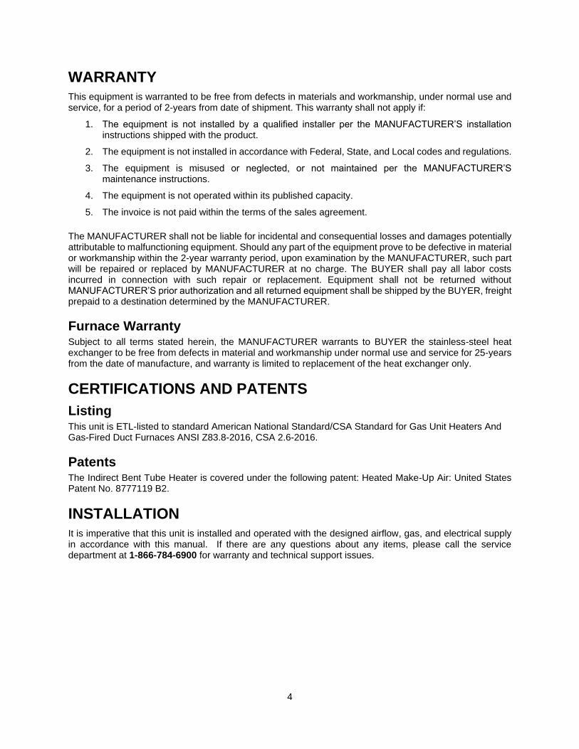
Mechanical WARNING: DO NOT RAISE VENTILATOR BY THE INTAKE HOOD, BLOWER OR MOTOR SHAFT, OR BEARINGS – USE ALL LIFTING LUGS PROVIDED WITH A SPREADER BAR OR SLINGS UNDER THE UNIT
Site Preparation
1. Provide clearance around installation site to safely rig and lift equipment into its final position. Supports must adequately support equipment. Refer to manufacturer’s estimated weights.
2. Consider general service and installation space when locating unit.
3. Locate unit close to the space it will serve to reduce long, twisted duct runs.
4. Do not allow air intake to face prevailing winds. Support unit above ground or at roof level high enough to prevent precipitation from being drawn into its inlet. The inlet must also be located at least 10 feet away from any exhaust vents. The heater inlet shall be located in accordance with the applicable building code provisions for ventilation air.
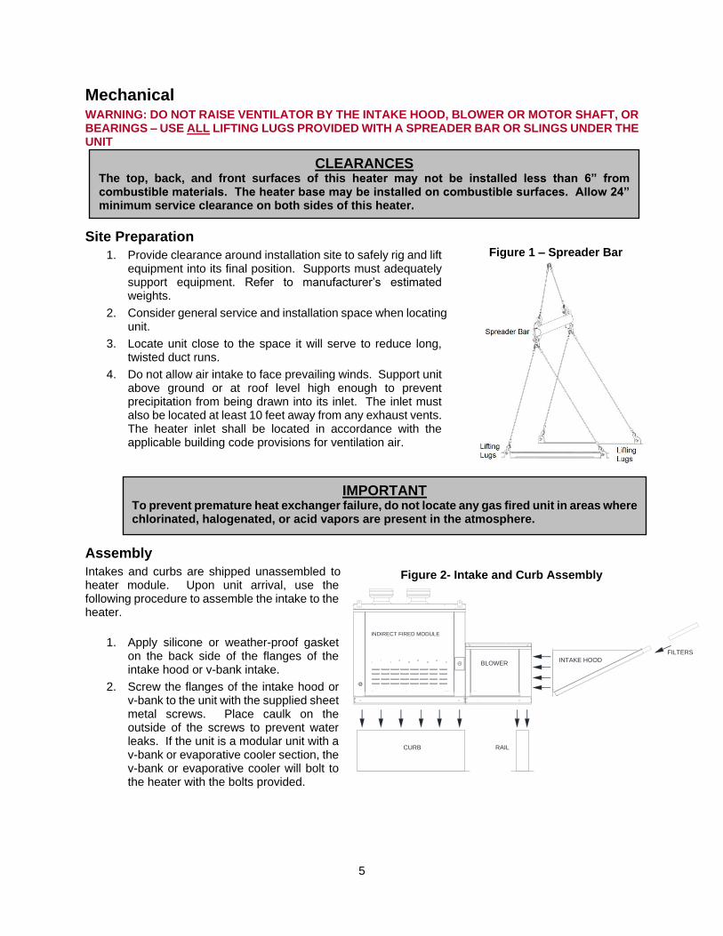
Assembly
Intakes and curbs are shipped unassembled to heater module. Upon unit arrival, use the following procedure to assemble the intake to the heater.
1. Apply silicone or weather-proof gasket on the back side of the flanges of the intake hood or v-bank intake.
2. Screw the flanges of the intake hood or v-bank to the unit with the supplied sheet metal screws. Place caulk on the outside of the screws to prevent water leaks. If the unit is a modular unit with a v-bank or evaporative cooler section, the v-bank or evaporative cooler will bolt to the heater with the bolts provided.
Figure 2- Intake and Curb Assembly
CLEARANCES
The top, back, and front surfaces of this heater may not be installed less than 6” from combustible materials. The heater base may be installed on combustible surfaces. Allow 24” minimum service clearance on both sides of this heater.
IMPORTANT
To prevent premature heat exchanger failure, do not locate any gas fired unit in areas where chlorinated, halogenated, or acid vapors are present in the atmosphere.
FILTERS
INTAKE HOODBLOWER
RAIL
INDIRECT FIRED MODULE
CURB
Figure 1 – Spreader Bar
6
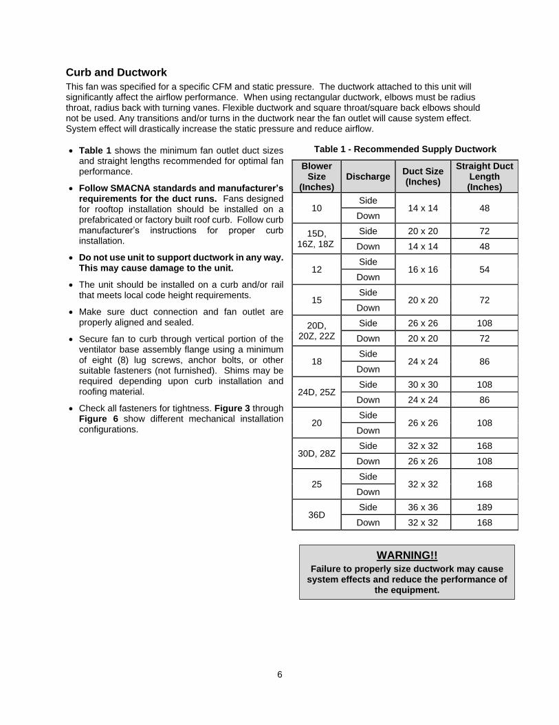
Curb and Ductwork
This fan was specified for a specific CFM and static pressure. The ductwork attached to this unit will significantly affect the airflow performance. When using rectangular ductwork, elbows must be radius throat, radius back with turning vanes. Flexible ductwork and square throat/square back elbows should not be used. Any transitions and/or turns in the ductwork near the fan outlet will cause system effect. System effect will drastically increase the static pressure and reduce airflow.
• Table 1 shows the minimum fan outlet duct sizes and straight lengths recommended for optimal fan performance.
• Follow SMACNA standards and manufacturer’s requirements for the duct runs. Fans designed for rooftop installation should be installed on a prefabricated or factory built roof curb. Follow curb manufacturer’s instructions for proper curb installation.
• Do not use unit to support ductwork in any way. This may cause damage to the unit.
• The unit should be installed on a curb and/or rail that meets local code height requirements.
• Make sure duct connection and fan outlet are properly aligned and sealed.
• Secure fan to curb through vertical portion of the ventilator base assembly flange using a minimum of eight (8) lug screws, anchor bolts, or other suitable fasteners (not furnished). Shims may be required depending upon curb installation and roofing material.
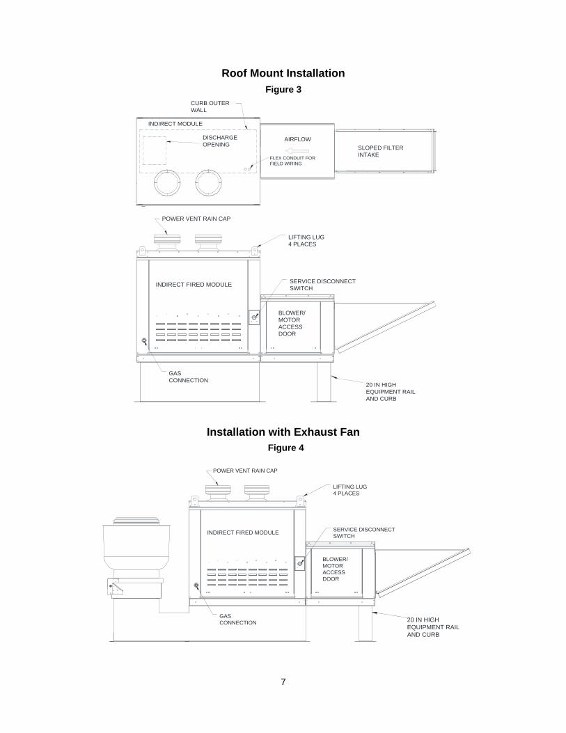
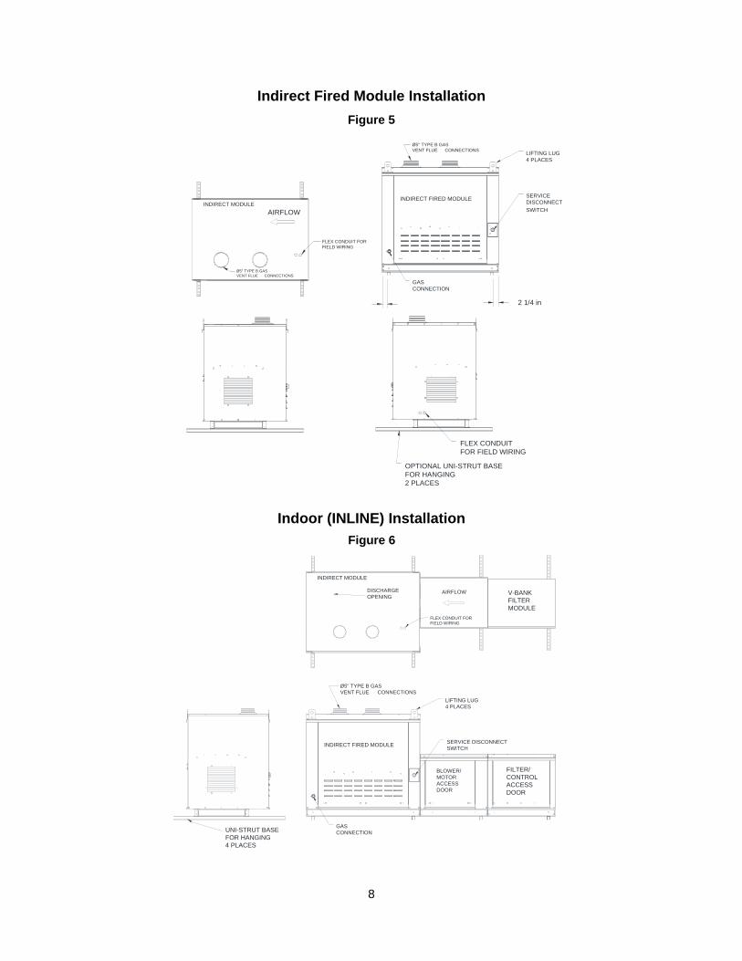
• Check all fasteners for tightness. Figure 3 through Figure 6 show different mechanical installation configurations.
Table 1 - Recommended Supply Ductwork
Blower Size
(Inches) Discharge
Duct Size (Inches)
Straight Duct Length (Inches)
10 Side
14 x 14 48 Down
15D, 16Z, 18Z
Side 20 x 20 72
Down 14 x 14 48
12 Side
16 x 16 54 Down
15 Side
20 x 20 72 Down
20D, 20Z, 22Z
Side 26 x 26 108
Down 20 x 20 72
18 Side
24 x 24 86 Down
24D, 25Z Side 30 x 30 108
Down 24 x 24 86
20 Side
26 x 26 108 Down
30D, 28Z Side 32 x 32 168
Down 26 x 26 108
25 Side
32 x 32 168 Down
36D Side 36 x 36 189
Down 32 x 32 168
WARNING!!
Failure to properly size ductwork may cause system effects and reduce the performance of
the equipment.
7
Roof Mount Installation
Installation with Exhaust Fan
Figure 3
Figure 4
ACCESS
4 PLACES
SERVICE DISCONNECT
DOOR
SWITCH
CONNECTION
GAS
MOTOR
BLOWER/
LIFTING LUG
POWER VENT RAIN CAP
INDIRECT FIRED MODULE
20 IN HIGH
AND CURB
EQUIPMENT RAIL
POWER VENT RAIN CAP
DISCHARGE
CURB OUTER
LIFTING LUG
WALL
4 PLACES
INDIRECT MODULE
20 IN HIGH
AND CURB
EQUIPMENT RAIL
GAS
CONNECTION
SLOPED FILTER
INTAKE
OPENINGAIRFLOW
SERVICE DISCONNECT INDIRECT FIRED MODULE
FLEX CONDUIT FOR
SWITCH
FIELD WIRING
DOOR
ACCESS
MOTOR
BLOWER/
8
Indirect Fired Module Installation
Indoor (INLINE) Installation
Figure 5
Figure 6
CONNECTIONS
FLEX CONDUIT FOR
Ø5" TYPE B GAS
VENT FLUE
FIELD WIRING
GAS
CONNECTION
Ø5" TYPE B GAS
VENT FLUE CONNECTIONS
2 1/4 in
INDIRECT FIRED MODULE
OPTIONAL UNI-STRUT BASE
FLEX CONDUIT
FOR FIELD WIRING
2 PLACES
AIRFLOW
FOR HANGING
4 PLACES
SWITCH
LIFTING LUG
INDIRECT MODULE DISCONNECT
SERVICE
SERVICE DISCONNECT
DOOR
FIELD WIRING
FOR HANGING
ACCESS
4 PLACES
Ø5" TYPE B GAS
VENT FLUE
ACCESS
MODULE
V-BANKAIRFLOW
4 PLACES
MOTOR
OPENING
FLEX CONDUIT FOR
CONNECTIONS
CONTROL
FILTER
INDIRECT MODULE
BLOWER/
LIFTING LUG
SWITCH
DISCHARGE
FILTER/
UNI-STRUT BASE
DOOR
INDIRECT FIRED MODULE
GAS
CONNECTION
9
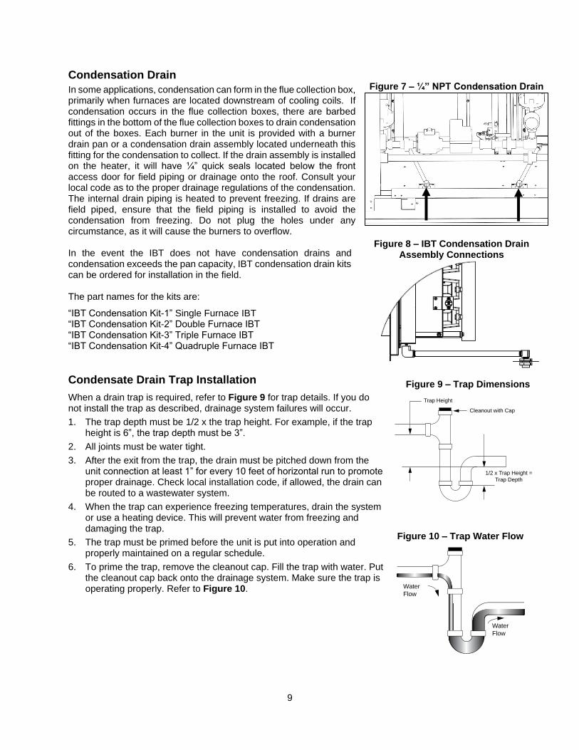
Condensation Drain
In some applications, condensation can form in the flue collection box, primarily when furnaces are located downstream of cooling coils. If condensation occurs in the flue collection boxes, there are barbed fittings in the bottom of the flue collection boxes to drain condensation out of the boxes. Each burner in the unit is provided with a burner drain pan or a condensation drain assembly located underneath this fitting for the condensation to collect. If the drain assembly is installed on the heater, it will have ¼” quick seals located below the front access door for field piping or drainage onto the roof. Consult your local code as to the proper drainage regulations of the condensation. The internal drain piping is heated to prevent freezing. If drains are field piped, ensure that the field piping is installed to avoid the condensation from freezing. Do not plug the holes under any circumstance, as it will cause the burners to overflow. In the event the IBT does not have condensation drains and condensation exceeds the pan capacity, IBT condensation drain kits can be ordered for installation in the field. The part names for the kits are:
“IBT Condensation Kit-1” Single Furnace IBT “IBT Condensation Kit-2” Double Furnace IBT “IBT Condensation Kit-3” Triple Furnace IBT “IBT Condensation Kit-4” Quadruple Furnace IBT
Condensate Drain Trap Installation
When a drain trap is required, refer to Figure 9 for trap details. If you do not install the trap as described, drainage system failures will occur.
1. The trap depth must be 1/2 x the trap height. For example, if the trap height is 6”, the trap depth must be 3”.
2. All joints must be water tight.
3. After the exit from the trap, the drain must be pitched down from the unit connection at least 1” for every 10 feet of horizontal run to promote proper drainage. Check local installation code, if allowed, the drain can be routed to a wastewater system.
4. When the trap can experience freezing temperatures, drain the system or use a heating device. This will prevent water from freezing and damaging the trap.
5. The trap must be primed before the unit is put into operation and properly maintained on a regular schedule.
6. To prime the trap, remove the cleanout cap. Fill the trap with water. Put the cleanout cap back onto the drainage system. Make sure the trap is operating properly. Refer to Figure 10.
Figure 9 – Trap Dimensions
Figure 7 – ¼” NPT Condensation Drain
Figure 8 – IBT Condensation Drain Assembly Connections
Figure 10 – Trap Water Flow
Water
Flow
Water
Flow
Trap Height
Cleanout with Cap
1/2 x Trap Height =
Trap Depth
10
Indoor Flue Venting
This appliance requires a Category III venting system. Refer to appliance manufacturer’s installation instructions for proper vent installation. Indoor gas fired heating equipment must be vented. Do not operate un-vented. Gas fired heating equipment which has been improperly vented, or which experiences a blocked vent condition may emit flue gases into heated spaces.
Use only venting materials and components that are UL listed and approved for Category III venting systems. Do not mix pipe, fittings, or joining methods from different manufacturers.
General Venting Guidelines
1. Installation of venting must conform to local building codes, or in the absence of local codes, follow the National Fuel Gas Code.
2. On Units with multiple furnaces, each furnace must be ducted to the outside using its own isolated duct run. Ducts used on each single furnace MUST NOT be connected together in any fashion. Failure to adhere to this may result in a build-up of Carbon-Monoxide in the space when the furnace is operating with less than all of its furnaces powered.
3. Do not use a vent pipe smaller than the size of the outlet on the heater.
4. Install with a minimum upward slope from unit of ¼ inch per foot and suspend from overhead structure at points no greater than 3 feet apart. For best venting, put as much vertical vent as close to the unit as possible.
5. Fasten individual lengths of vent together with at least three corrosion resistant sheet metal screws.
6. Vent pipes should be fitted with a tee with a drip leg and clean out tap at the low point in the vent run. This should be inspected and cleaned out periodically during the heating season.
7. Do NOT use dampers or other devices in the vent or combustion air pipes.
8. Use a vent terminal to reduce downdrafts and moisture in the vent line.
9. A vent system that terminates vertically but has a horizontal run that exceeds 75% of the vertical rise is considered horizontal.
10. Pressures in Category III venting systems are positive, and therefore care must be taken to prevent flue products from entering the heated space.
11. Vent pipes must all be sealed and gastight.
Vertically Vented Furnaces
1. Use single wall or double wall (Type B) vent pipe of a diameter listed in the following table for the appropriate model.
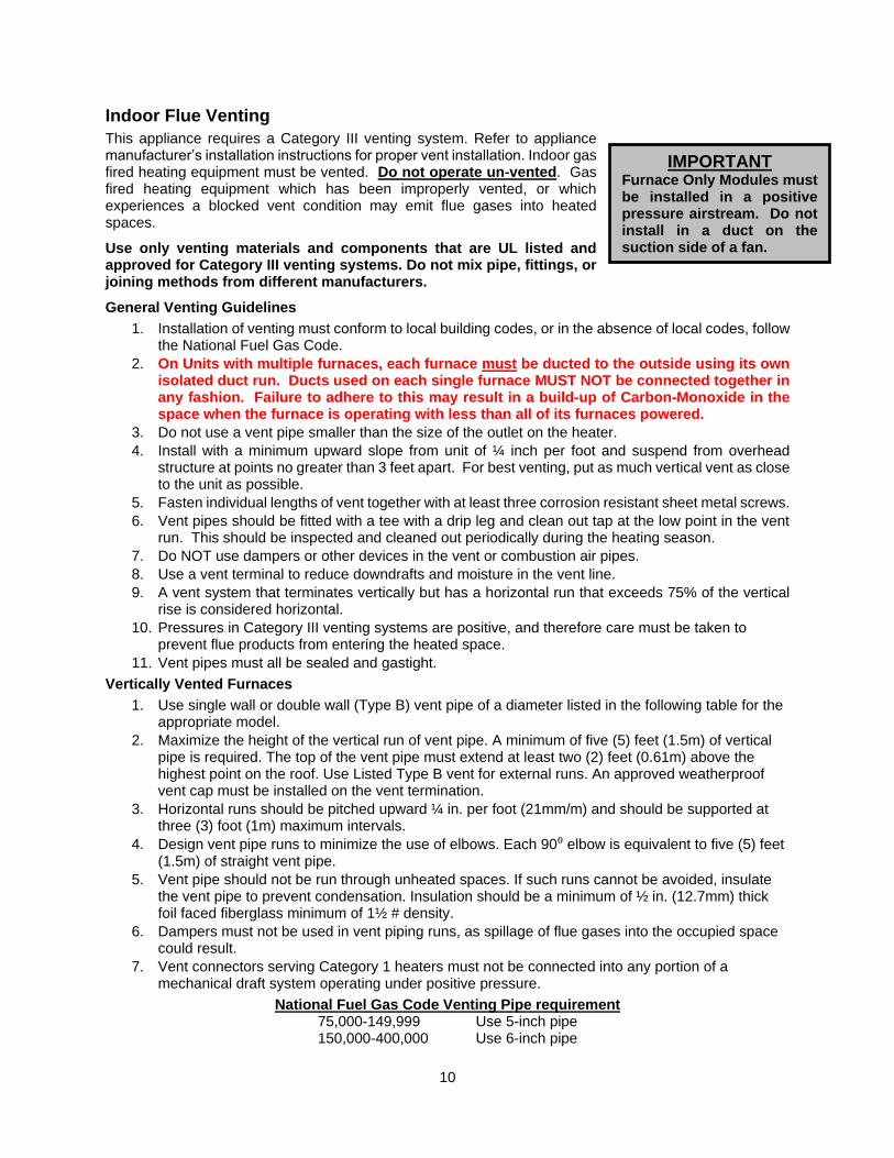
2. Maximize the height of the vertical run of vent pipe. A minimum of five (5) feet (1.5m) of vertical pipe is required. The top of the vent pipe must extend at least two (2) feet (0.61m) above the highest point on the roof. Use Listed Type B vent for external runs. An approved weatherproof vent cap must be installed on the vent termination.
3. Horizontal runs should be pitched upward ¼ in. per foot (21mm/m) and should be supported at three (3) foot (1m) maximum intervals.
4. Design vent pipe runs to minimize the use of elbows. Each 90⁰ elbow is equivalent to five (5) feet (1.5m) of straight vent pipe.
5. Vent pipe should not be run through unheated spaces. If such runs cannot be avoided, insulate the vent pipe to prevent condensation. Insulation should be a minimum of ½ in. (12.7mm) thick foil faced fiberglass minimum of 1½ # density.
6. Dampers must not be used in vent piping runs, as spillage of flue gases into the occupied space could result.
7. Vent connectors serving Category 1 heaters must not be connected into any portion of a mechanical draft system operating under positive pressure.
National Fuel Gas Code Venting Pipe requirement 75,000-149,999 Use 5-inch pipe 150,000-400,000 Use 6-inch pipe
IMPORTANT
Furnace Only Modules must be installed in a positive pressure airstream. Do not install in a duct on the suction side of a fan.
11
Figure 11 - Vertical Venting
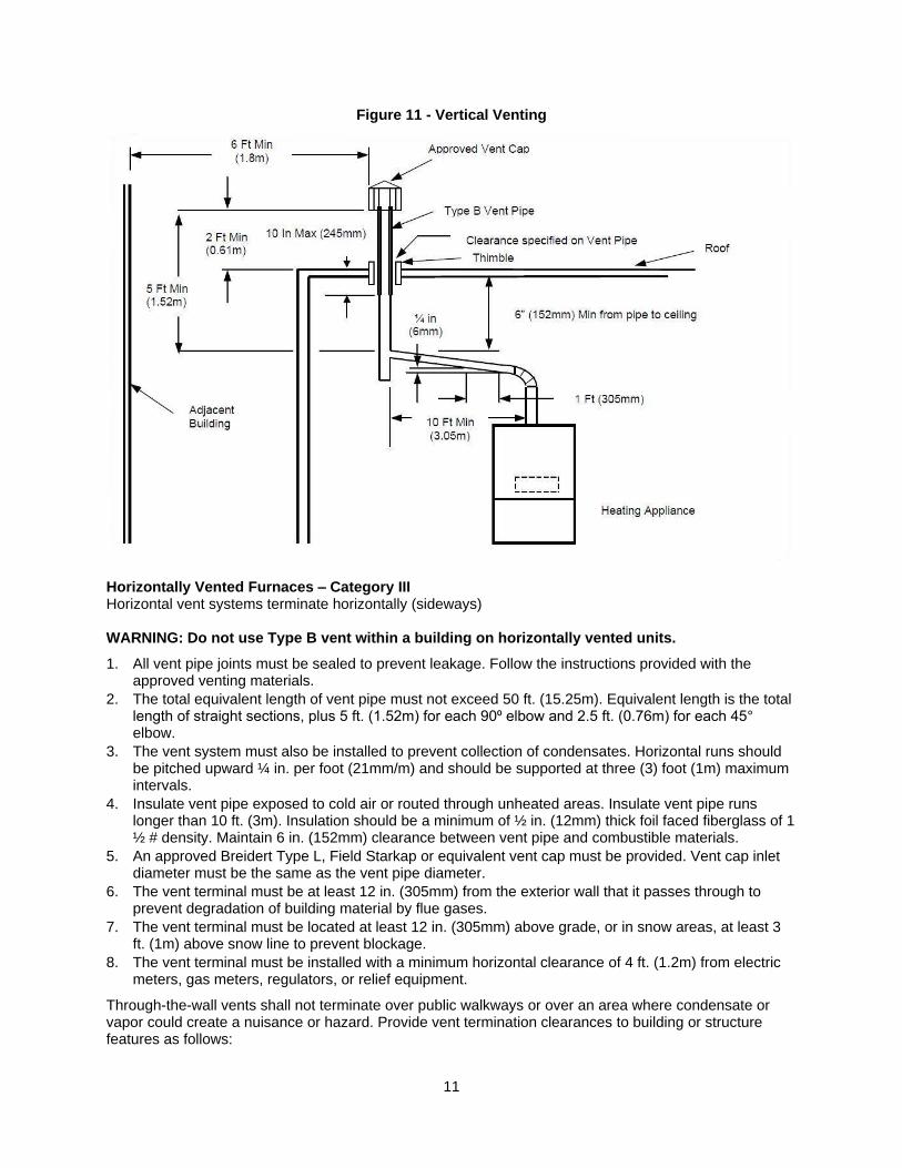
Horizontally Vented Furnaces – Category III Horizontal vent systems terminate horizontally (sideways) WARNING: Do not use Type B vent within a building on horizontally vented units.
1. All vent pipe joints must be sealed to prevent leakage. Follow the instructions provided with the approved venting materials.
2. The total equivalent length of vent pipe must not exceed 50 ft. (15.25m). Equivalent length is the total length of straight sections, plus 5 ft. (1.52m) for each 90⁰ elbow and 2.5 ft. (0.76m) for each 45° elbow.
3. The vent system must also be installed to prevent collection of condensates. Horizontal runs should be pitched upward ¼ in. per foot (21mm/m) and should be supported at three (3) foot (1m) maximum intervals.
4. Insulate vent pipe exposed to cold air or routed through unheated areas. Insulate vent pipe runs longer than 10 ft. (3m). Insulation should be a minimum of ½ in. (12mm) thick foil faced fiberglass of 1 ½ # density. Maintain 6 in. (152mm) clearance between vent pipe and combustible materials.
5. An approved Breidert Type L, Field Starkap or equivalent vent cap must be provided. Vent cap inlet diameter must be the same as the vent pipe diameter.
6. The vent terminal must be at least 12 in. (305mm) from the exterior wall that it passes through to prevent degradation of building material by flue gases.
7. The vent terminal must be located at least 12 in. (305mm) above grade, or in snow areas, at least 3 ft. (1m) above snow line to prevent blockage.
8. The vent terminal must be installed with a minimum horizontal clearance of 4 ft. (1.2m) from electric meters, gas meters, regulators, or relief equipment.
Through-the-wall vents shall not terminate over public walkways or over an area where condensate or vapor could create a nuisance or hazard. Provide vent termination clearances to building or structure features as follows:
12
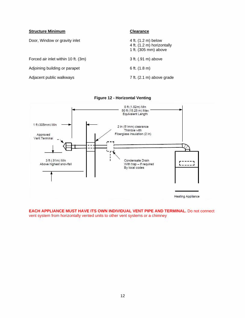
Structure Minimum Clearance Door, Window or gravity inlet 4 ft. (1.2 m) below
4 ft. (1.2 m) horizontally 1 ft. (305 mm) above
Forced air inlet within 10 ft. (3m) 3 ft. (.91 m) above Adjoining building or parapet 6 ft. (1.8 m) Adjacent public walkways 7 ft. (2.1 m) above grade
Figure 12 - Horizontal Venting
EACH APPLIANCE MUST HAVE ITS OWN INDIVIDUAL VENT PIPE AND TERMINAL. Do not connect vent system from horizontally vented units to other vent systems or a chimney
13
Gas Installation of gas piping must conform with local building codes, or in the absence of local codes, to the National Fuel Gas Code, ANSI Z223.1 (NFPA 54) – latest edition. In Canada, installation must be in accordance with CAN/CGA-B149.1 for natural gas units and CAN/CGA-B149.2 for propane units.
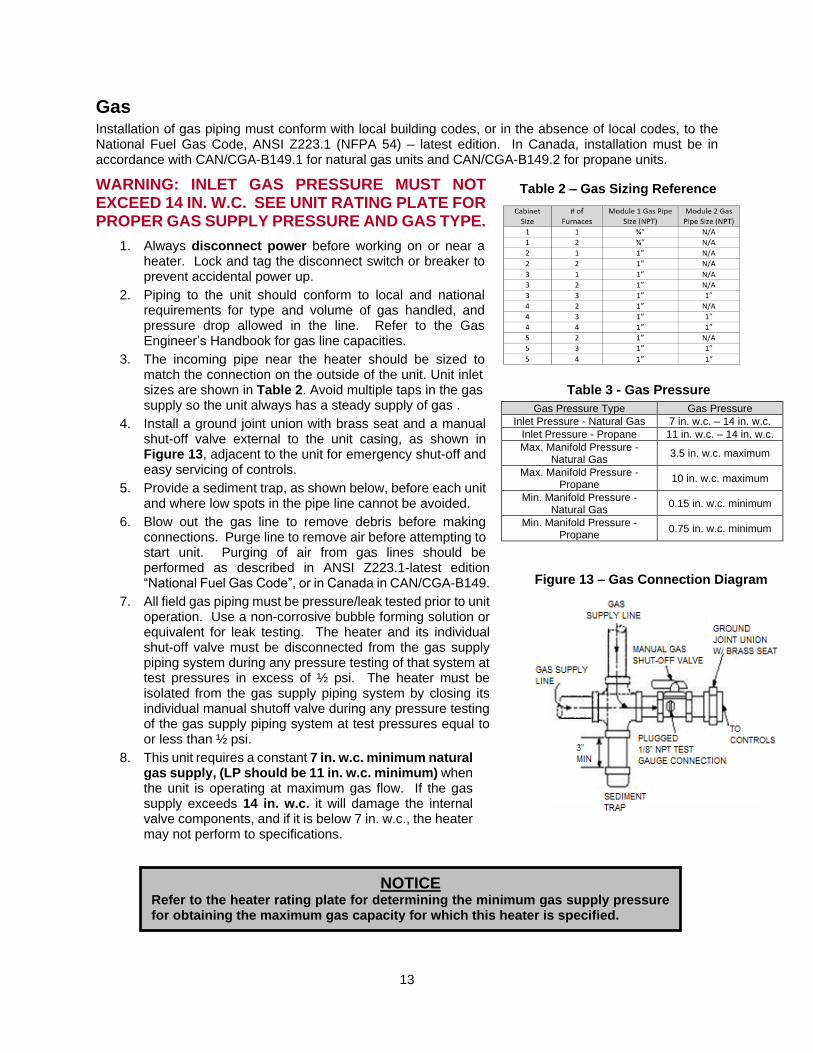
WARNING: INLET GAS PRESSURE MUST NOT EXCEED 14 IN. W.C. SEE UNIT RATING PLATE FOR PROPER GAS SUPPLY PRESSURE AND GAS TYPE.
1. Always disconnect power before working on or near a heater. Lock and tag the disconnect switch or breaker to prevent accidental power up.
2. Piping to the unit should conform to local and national requirements for type and volume of gas handled, and pressure drop allowed in the line. Refer to the Gas Engineer’s Handbook for gas line capacities.
3. The incoming pipe near the heater should be sized to match the connection on the outside of the unit. Unit inlet sizes are shown in Table 2. Avoid multiple taps in the gas supply so the unit always has a steady supply of gas .
4. Install a ground joint union with brass seat and a manual shut-off valve external to the unit casing, as shown in Figure 13, adjacent to the unit for emergency shut-off and easy servicing of controls.
5. Provide a sediment trap, as shown below, before each unit and where low spots in the pipe line cannot be avoided.
6. Blow out the gas line to remove debris before making connections. Purge line to remove air before attempting to start unit. Purging of air from gas lines should be performed as described in ANSI Z223.1-latest edition “National Fuel Gas Code”, or in Canada in CAN/CGA-B149.
7. All field gas piping must be pressure/leak tested prior to unit operation. Use a non-corrosive bubble forming solution or equivalent for leak testing. The heater and its individual shut-off valve must be disconnected from the gas supply piping system during any pressure testing of that system at test pressures in excess of ½ psi. The heater must be isolated from the gas supply piping system by closing its individual manual shutoff valve during any pressure testing of the gas supply piping system at test pressures equal to or less than ½ psi.
8. This unit requires a constant 7 in. w.c. minimum natural gas supply, (LP should be 11 in. w.c. minimum) when the unit is operating at maximum gas flow. If the gas supply exceeds 14 in. w.c. it will damage the internal valve components, and if it is below 7 in. w.c., the heater may not perform to specifications.
Gas Pressure Type Gas Pressure
Inlet Pressure - Natural Gas 7 in. w.c. – 14 in. w.c.
Inlet Pressure - Propane 11 in. w.c. – 14 in. w.c.
Max. Manifold Pressure - Natural Gas
3.5 in. w.c. maximum
Max. Manifold Pressure - Propane
10 in. w.c. maximum
Min. Manifold Pressure - Natural Gas
0.15 in. w.c. minimum
Min. Manifold Pressure - Propane
0.75 in. w.c. minimum
NOTICE
Refer to the heater rating plate for determining the minimum gas supply pressure for obtaining the maximum gas capacity for which this heater is specified.
Table 2 – Gas Sizing Reference
Table 3 - Gas Pressure
Figure 13 – Gas Connection Diagram
14
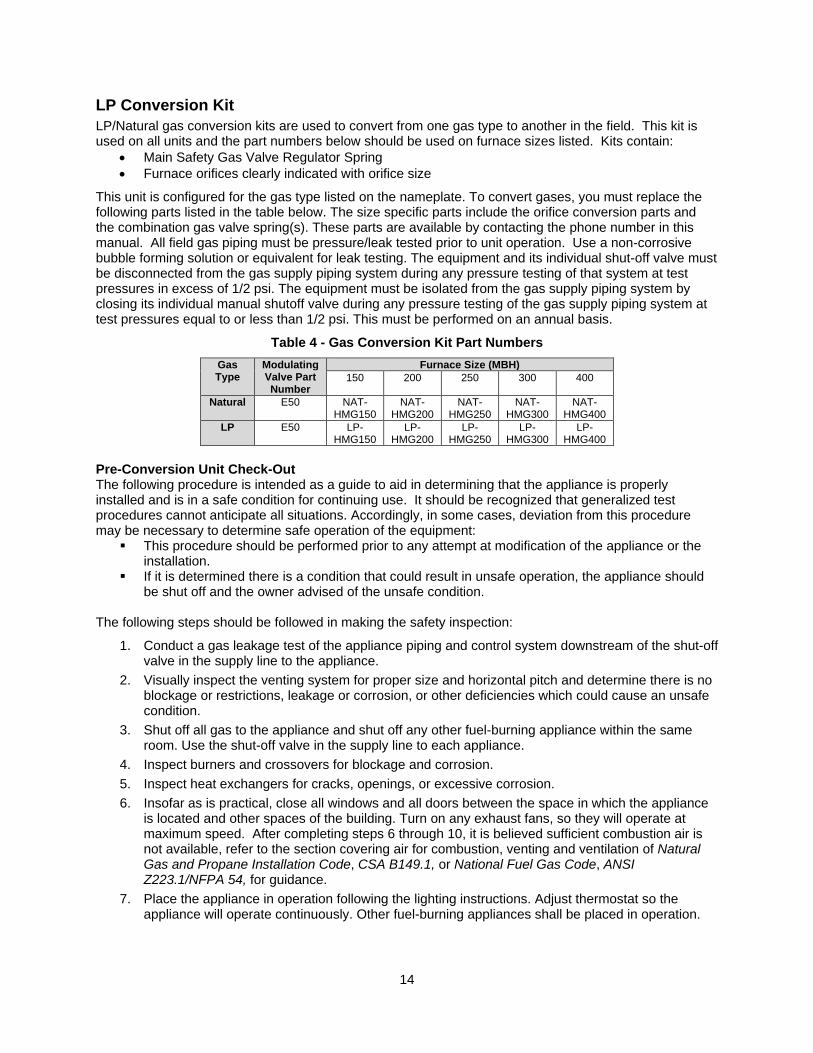
LP Conversion Kit
LP/Natural gas conversion kits are used to convert from one gas type to another in the field. This kit is used on all units and the part numbers below should be used on furnace sizes listed. Kits contain:
• Main Safety Gas Valve Regulator Spring
• Furnace orifices clearly indicated with orifice size
This unit is configured for the gas type listed on the nameplate. To convert gases, you must replace the following parts listed in the table below. The size specific parts include the orifice conversion parts and the combination gas valve spring(s). These parts are available by contacting the phone number in this manual. All field gas piping must be pressure/leak tested prior to unit operation. Use a non-corrosive bubble forming solution or equivalent for leak testing. The equipment and its individual shut-off valve must be disconnected from the gas supply piping system during any pressure testing of that system at test pressures in excess of 1/2 psi. The equipment must be isolated from the gas supply piping system by closing its individual manual shutoff valve during any pressure testing of the gas supply piping system at test pressures equal to or less than 1/2 psi. This must be performed on an annual basis.
Table 4 - Gas Conversion Kit Part Numbers
Gas Type
Modulating Valve Part Number
Furnace Size (MBH)
150 200 250 300 400
Natural E50 NAT-HMG150
NAT-HMG200
NAT-HMG250
NAT-HMG300
NAT-HMG400
LP E50 LP-HMG150
LP-HMG200
LP-HMG250
LP-HMG300
LP-HMG400
Pre-Conversion Unit Check-Out The following procedure is intended as a guide to aid in determining that the appliance is properly installed and is in a safe condition for continuing use. It should be recognized that generalized test procedures cannot anticipate all situations. Accordingly, in some cases, deviation from this procedure may be necessary to determine safe operation of the equipment:
▪ This procedure should be performed prior to any attempt at modification of the appliance or the installation.
▪ If it is determined there is a condition that could result in unsafe operation, the appliance should be shut off and the owner advised of the unsafe condition.
The following steps should be followed in making the safety inspection:
1. Conduct a gas leakage test of the appliance piping and control system downstream of the shut-off valve in the supply line to the appliance.
2. Visually inspect the venting system for proper size and horizontal pitch and determine there is no blockage or restrictions, leakage or corrosion, or other deficiencies which could cause an unsafe condition.
3. Shut off all gas to the appliance and shut off any other fuel-burning appliance within the same room. Use the shut-off valve in the supply line to each appliance.
4. Inspect burners and crossovers for blockage and corrosion.
5. Inspect heat exchangers for cracks, openings, or excessive corrosion.
6. Insofar as is practical, close all windows and all doors between the space in which the appliance is located and other spaces of the building. Turn on any exhaust fans, so they will operate at maximum speed. After completing steps 6 through 10, it is believed sufficient combustion air is not available, refer to the section covering air for combustion, venting and ventilation of Natural Gas and Propane Installation Code, CSA B149.1, or National Fuel Gas Code, ANSI Z223.1/NFPA 54, for guidance.
7. Place the appliance in operation following the lighting instructions. Adjust thermostat so the appliance will operate continuously. Other fuel-burning appliances shall be placed in operation.
15
8. Determine that the pilot is burning properly and that the main burner ignition is satisfactory by interrupting and re-establishing the electrical supply to the appliance in any convenient manner;
a. Visually determine that main burner gas is burning properly, i.e. no floating, lifting, or flashback. Adjust the primary air shutter(s) as required.
b. If the appliance is equipped with high- and low-flame control, or flame modulation, check for proper main burner operation at low flame.
9. Test for spillage at the draft hood relief opening after 5 minutes of main burner operation. Use a draft gauge, the flame of a match, or candle.
10. Return doors, windows, exhaust fans, and all other fuel-burning appliances to their previous conditions of use.
11. Check both limit control and fan control for proper operation. Limit control operation can be checked by temporarily disconnecting the electrical supply to the blower motor and determining that the limit control acts to shut off the main burner gas.
16
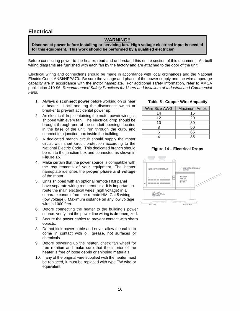
Electrical
Before connecting power to the heater, read and understand this entire section of this document. As-built wiring diagrams are furnished with each fan by the factory and are attached to the door of the unit. Electrical wiring and connections should be made in accordance with local ordinances and the National Electric Code, ANSI/NFPA70. Be sure the voltage and phase of the power supply and the wire amperage capacity are in accordance with the motor nameplate. For additional safety information, refer to AMCA publication 410-96, Recommended Safety Practices for Users and Installers of Industrial and Commercial Fans.
1. Always disconnect power before working on or near a heater. Lock and tag the disconnect switch or breaker to prevent accidental power up.
2. An electrical drop containing the motor power wiring is shipped with every fan. The electrical drop should be brought through one of the conduit openings located in the base of the unit, run through the curb, and connect to a junction box inside the building.
3. A dedicated branch circuit should supply the motor circuit with short circuit protection according to the National Electric Code. This dedicated branch should be run to the junction box and connected as shown in Figure 15.
4. Make certain that the power source is compatible with the requirements of your equipment. The heater nameplate identifies the proper phase and voltage of the motor.
5. Units shipped with an optional remote HMI panel have separate wiring requirements. It is important to route the main electrical wires (high voltage) in a separate conduit from the remote HMI Cat 5 wiring (low voltage). Maximum distance on any low voltage wire is 1000 feet.
6. Before connecting the heater to the building’s power source, verify that the power line wiring is de-energized.
7. Secure the power cables to prevent contact with sharp objects.
8. Do not kink power cable and never allow the cable to come in contact with oil, grease, hot surfaces or chemicals.
9. Before powering up the heater, check fan wheel for free rotation and make sure that the interior of the heater is free of loose debris or shipping materials.
10. If any of the original wire supplied with the heater must be replaced, it must be replaced with type TW wire or equivalent.
WARNING!!
Disconnect power before installing or servicing fan. High voltage electrical input is needed for this equipment. This work should be performed by a qualified electrician.
Wire Size AWG Maximum Amps
14 15
12 20
10 30
8 50
6 65
4 85
Table 5 - Copper Wire Ampacity
Figure 14 – Electrical Drops
20 IN HIGH
Motor Drop
SERVICE DISCONNECT
EQUIPMENT RAIL
ACCESS
SWITCH
Control Drop
AND CURB
DOOR
BLOWER/
MOTOR
INDIRECT FIRED MODULE

17
Input AC Power
1. Circuit breakers feeding the VFDs are recommended to be thermal-magnetic and fast acting. They should be sized based on the VFD amperage and according to Table 6. Refer to the installation schematic for exact breaker sizing.
2. Each VFD should be fed by its own breaker. If multiple VFDs are to be combined on the same breaker, each drive should have its own protection measure (fuses or miniature circuit breaker) downstream from the breaker.
3. Input AC line wires should be run in conduit from the breaker panel to the drives. AC input power to multiple VFDs can be run in a single conduit if needed. Do not combine input and output power cables in the same conduit.
4. The VFD should be grounded on the terminal marked PE. A separate insulated ground wire must be provided to each VFD from the electrical panel. This will reduce the noise being radiated in other equipment.
5. Motors should be grounded to the VFD ground terminal only. Do not connect the motor ground to the heater ground terminal.
Fan to Building Wiring Connection
Figure 15
BK
120V 1 PH.
Standing
Power
120V 1 PH.
Standing
Power
BKBK
120V 1 PH.
Standing
Power
WH
208-240
1 PH.3 PH.
WH GRGR
Customer
supplied
wiring from
building
power or pre
wired control
panel
Customer
supplied
wiring from
building
power or pre
wired control
panel
Factory
wiring
GR
Customer
supplied
wiring from
building
power or pre
wired control
panelBK
Gal-flex
conduit
(in unit)
Gal-flex
conduit
(in unit)
Disconnect
Switch
Factory
wiring
Disconnect
Switch
Factory
wiring
BK
208-240V 1 PH.120V 1 PH.
Gal-flex
conduit
(in unit)
208-240/460/600V 3 PH.
Disconnect
Switch
WH BKBK BK
18
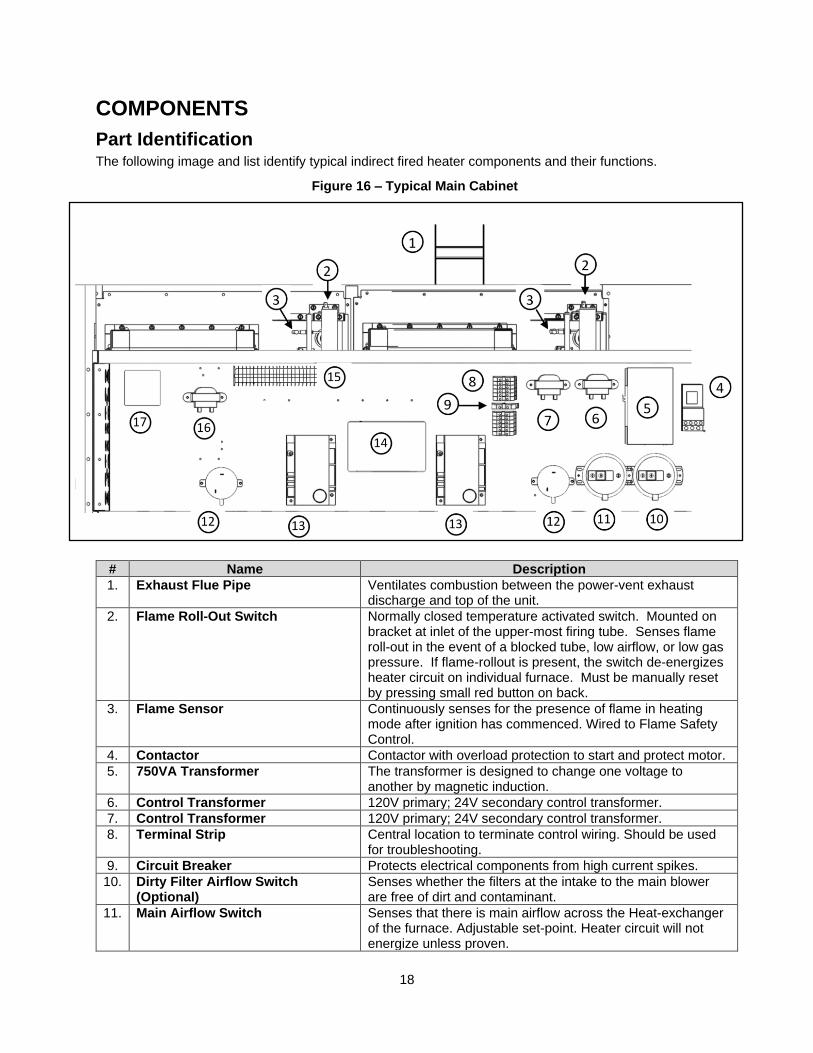
COMPONENTS
Part Identification
The following image and list identify typical indirect fired heater components and their functions.
# Name Description
1. Exhaust Flue Pipe Ventilates combustion between the power-vent exhaust discharge and top of the unit.
2. Flame Roll-Out Switch Normally closed temperature activated switch. Mounted on bracket at inlet of the upper-most firing tube. Senses flame roll-out in the event of a blocked tube, low airflow, or low gas pressure. If flame-rollout is present, the switch de-energizes heater circuit on individual furnace. Must be manually reset by pressing small red button on back.
3. Flame Sensor Continuously senses for the presence of flame in heating mode after ignition has commenced. Wired to Flame Safety Control.
4. Contactor Contactor with overload protection to start and protect motor.
5. 750VA Transformer The transformer is designed to change one voltage to another by magnetic induction.
6. Control Transformer 120V primary; 24V secondary control transformer.
7. Control Transformer 120V primary; 24V secondary control transformer.
8. Terminal Strip Central location to terminate control wiring. Should be used for troubleshooting.
9. Circuit Breaker Protects electrical components from high current spikes.
10. Dirty Filter Airflow Switch (Optional)
Senses whether the filters at the intake to the main blower are free of dirt and contaminant.
11. Main Airflow Switch Senses that there is main airflow across the Heat-exchanger of the furnace. Adjustable set-point. Heater circuit will not energize unless proven.
Figure 16 – Typical Main Cabinet
19
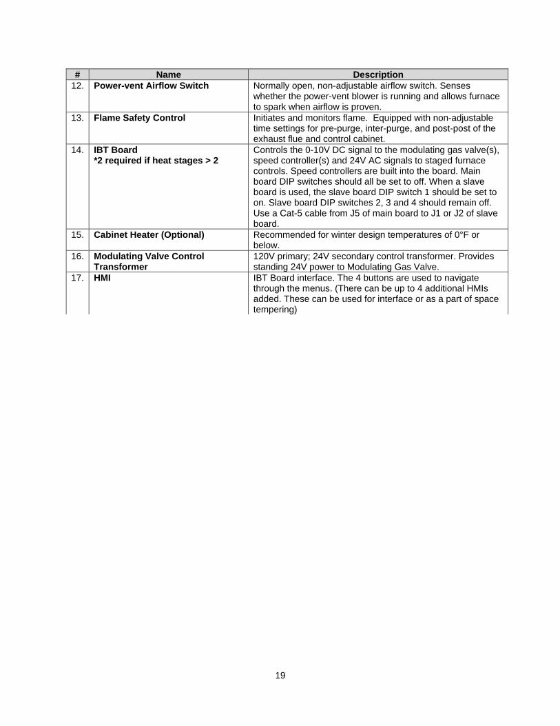
# Name Description
12. Power-vent Airflow Switch Normally open, non-adjustable airflow switch. Senses whether the power-vent blower is running and allows furnace to spark when airflow is proven.
13. Flame Safety Control Initiates and monitors flame. Equipped with non-adjustable time settings for pre-purge, inter-purge, and post-post of the exhaust flue and control cabinet.
14. IBT Board *2 required if heat stages > 2
Controls the 0-10V DC signal to the modulating gas valve(s), speed controller(s) and 24V AC signals to staged furnace controls. Speed controllers are built into the board. Main board DIP switches should all be set to off. When a slave board is used, the slave board DIP switch 1 should be set to on. Slave board DIP switches 2, 3 and 4 should remain off. Use a Cat-5 cable from J5 of main board to J1 or J2 of slave board.
15. Cabinet Heater (Optional) Recommended for winter design temperatures of 0°F or below.
16. Modulating Valve Control Transformer
120V primary; 24V secondary control transformer. Provides standing 24V power to Modulating Gas Valve.
17. HMI IBT Board interface. The 4 buttons are used to navigate through the menus. (There can be up to 4 additional HMIs added. These can be used for interface or as a part of space tempering)
20
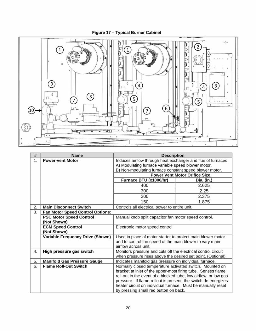
# Name Description
1. Power-vent Motor Induces airflow through heat exchanger and flue of furnaces A) Modulating furnace variable speed blower motor. B) Non-modulating furnace constant speed blower motor.
Power Vent Motor Orifice Size
Furnace BTU (x1000/hr) Dia. (in.)
400 2.625
300 2.25
200 2.375
150 1.875 2. Main Disconnect Switch Controls all electrical power to entire unit.
3. Fan Motor Speed Control Options:
PSC Motor Speed Control (Not Shown)
Manual knob split capacitor fan motor speed control.
ECM Speed Control (Not Shown)
Electronic motor speed control
Variable Frequency Drive (Shown) Used in place of motor starter to protect main blower motor and to control the speed of the main blower to vary main airflow across unit.
4. High pressure gas switch Monitors pressure and cuts off the electrical control circuit when pressure rises above the desired set point. (Optional)
5. Manifold Gas Pressure Gauge Indicates manifold gas pressure on individual furnace.
6. Flame Roll-Out Switch Normally closed temperature activated switch. Mounted on bracket at inlet of the upper-most firing tube. Senses flame roll-out in the event of a blocked tube, low airflow, or low gas pressure. If flame-rollout is present, the switch de-energizes heater circuit on individual furnace. Must be manually reset by pressing small red button on back.
Figure 17 – Typical Burner Cabinet

21
# Name Description
7. On/Off Gas Valve On/off gas valve with built in regulator and manual shut off switch. One used on each furnace gas train.
8. Modulating Gas Valve Controls the amount of gas to the furnace to meet desired discharge/Space temperature. (Modulating units only)
9. Low pressure gas switch Monitors pressure and cuts off the electrical control circuit when pressure drops below the desired set point. (Optional)
10. Main Inlet Gas Pressure Gauge Indicates inlet gas pressure to unit.
Not Shown:
- High Limit Switch
Normally closed high temperature switch. De-energizes heater circuit on individual furnace if temperature exceeds mechanical set-point. Automatic recycling. 200°F set-point.
- Spark Ignitor Powered by Flame safety control to initiate light-off.
- Discharge Sensor 10k Thermistor. Controls the discharge to which the heating module heats to and constantly tries to maintain. Freezestat and discharge Firestat functionality is built into this sensor if the options are enabled.
- Intake Air Sensor (not shown) 10k Thermistor. Reports intake temperature to the IBT board. Heating/cooling will activate based off the set points on the IBT Board. Does not control the temperature to which the unit heats the discharge. Located in the supply fan,
Motor Speed Control Options
ECM (Electronically Controlled Motor) Speed Control
EC motors and control allows accurate manual adjustment of fan speed. The benefit of EC motors is exceptional efficiency, performance, and motor life. When using an EC motor, the blower control should be set to ECM. This menu item is located under factory settings > unit options > blower configuration. Once this is set, there is a PWM rate setting under user settings. This will be used to control the speed of the EC motor. The PWM signal will be sent directly to the ECM via J13-(2) PWM + and J13-(9) PWM (–) pins.
NOTE: A Variable Frequency Drive (VFD) is required to adjust the speed control of a non-electrically commutated 3 phase direct drive motor.
External PWM Signal
The fan unit will be shipped with power wiring and communication wiring fed to an internal junction box. The fan is shipped with Shielded Twisted Pair (STP) wire which is used to wire to a remote PWM signal. Red wire is used to go to the positive PWM signal and black wire is used to go to the negative PWM signal. Reference schematics for all wiring connections. STP is connected to the communication wiring of the motor using wire nuts in the junction box. If a preset length of STP is provided, it will be connected to the junction box from the factory. Run the STP through any available knockout in the fan base.

22
Variable Frequency Drive Speed Control (Installation Instructions) ATTENTION! DO NOT CONNECT INCOMING AC POWER TO OUTPUT TERMINALS U, V, W. SEVERE DAMAGE TO THE DRIVE WILL RESULT. INPUT POWER MUST ALWAYS BE WIRED TO THE INPUT L TERMINAL CONNECTIONS (L1, L2, L3)
VFD Output Power
1. Motor wires from each VFD to its respective motor MUST be run in a separate steel conduit away from control wiring and incoming AC power wiring to avoid noise and crosstalk between drives. An insulated ground must be run from each VFD to its respective motor. Do not run different fan output power cables in the same conduit.
2. VFD mounted in ECP: If the distance between VFD and the motor is greater than the distances specified below, a load reactor should be used between VFD and motor. The load reactor should be sized accordingly and installed within 10 feet of the output of the VFD. 208/230V – Load reactor should be used when distance exceeds 250 feet. 460/480V – Load reactor should be used when distance exceeds 50 feet. 575/600V – Load reactor should be used when distance exceeds 25 feet.
3. VFD mounted in fan: The load reactor should be sized accordingly when VFD is mounted in the fan. 208/230V – Load reactor is optional but recommended for 15 HP and above motors. 460/480V – Load reactor is optional but recommended for 7.5 HP and above motors. 575V/600V – Load reactors are required for all HP motors.
4. If the distance between VFD and the motor is extremely long, up to 1000 FT, a dV/dT filter should be used. The VFD should be increased by 1 HP or to the next size VFD. The dV/dT filter should be sized accordingly and installed within 10 feet of the output of the VFD. 208/230V – dV/dT filter should be used when distance exceeds 400 feet. 460/480V – dV/dT filter should be used when distance exceeds 250 feet. 575/600V – dV/dT filter should be used when distance exceeds 150 feet.
5. No contactor should be installed between the drive and the motor. Operating such a device while the drive is running can potentially cause damage to the power components of the drive.
6. When a disconnect switch is installed between the drive and motor, the disconnect switch should only be operated when the drive is in a STOP state.
VFD Programming 1. The Drive should be programmed for the proper motor voltage. P107 is set to 0 (Low) if motor voltage
is 120V AC, 208V AC or 400V AC. P107 is set to 1 (High) if motor voltage is 230V AC, 480V AC or 575V AC.
2. The Drive should be programmed for the proper motor overload value. P108 is calculated as Motor FLA x 100 / Drive Output Rating (available in table below).
To enter the PROGRAM mode to access the parameters: 1. Press the Mode (M) button. This will activate the password prompt (PASS).
2. Use the Up and Down buttons to scroll to the password value (the factory default password is “0225”) and press the Mode (M) button. Once the correct password is entered, the display will read “P100”, which indicates that the PROGRAM mode has been accessed at the beginning of the parameter menu.
3. Use the Up and Down buttons to scroll to the desired parameter number.
4. Once the desired parameter is found, press the Mode (M) button to display the present parameter setting. The parameter value will begin blinking, indicating that the present parameter setting is being displayed. The value of the parameter can be changed by using the Up and Down buttons.
5. Pressing the Mode (M) button will store the new setting and also exit the PROGRAM mode. To change another parameter, press the Mode (M) button again to re-enter the PROGRAM mode. If the Mode button is pressed within 1 minute of exiting the PROGRAM mode, the password is not required to access the parameters. After one minute, the password must be re-entered in order to access the parameters again.
P500 parameter provides a history of the last 8 faults on the drive. It can be accessed without getting into PROGRAM mode.
23
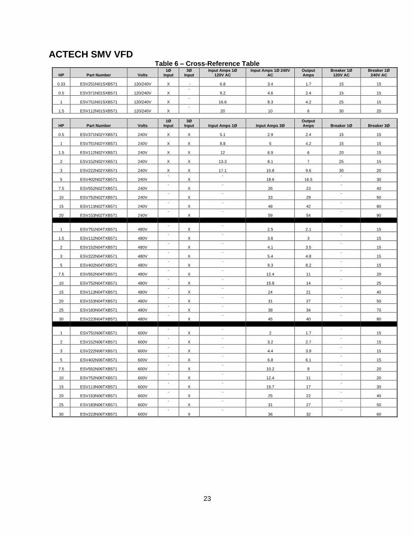
ACTECH SMV VFD Table 6 – Cross-Reference Table
HP Part Number Volts 1Ø
Input 3Ø
Input Input Amps 1Ø
120V AC Input Amps 1Ø 240V
AC Output Amps
Breaker 1Ø 120V AC
Breaker 1Ø 240V AC
0.33 ESV251N01SXB571 120/240V X - 6.8 3.4 1.7 15 15
0.5 ESV371N01SXB571 120/240V X -
9.2 4.6 2.4 15 15
1 ESV751N01SXB571 120/240V X -
16.6 8.3 4.2 25 15
1.5 ESV112N01SXB571 120/240V X -
20 10 6 30 20
HP Part Number Volts 1Ø
Input 3Ø
Input Input Amps 1Ø Input Amps 3Ø Output Amps Breaker 1Ø Breaker 3Ø
0.5 ESV371N02YXB571 240V X X 5.1 2.9 2.4 15 15
1 ESV751N02YXB571 240V X X 8.8 5 4.2 15 15
1.5 ESV112N02YXB571 240V X X 12 6.9 6 20 15
2 ESV152N02YXB571 240V X X 13.3 8.1 7 25 15
3 ESV222N02YXB571 240V X X 17.1 10.8 9.6 30 20
5 ESV402N02TXB571 240V -
X -
18.6 16.5 -
30
7.5 ESV552N02TXB571 240V -
X -
26 23 -
40
10 ESV752N02TXB571 240V -
X -
33 29 -
50
15 ESV113N02TXB571 240V -
X -
48 42 -
80
20 ESV153N02TXB571 240V -
X -
59 54 -
90
1 ESV751N04TXB571 480V -
X -
2.5 2.1 -
15
1.5 ESV112N04TXB571 480V -
X -
3.6 3 -
15
2 ESV152N04TXB571 480V -
X -
4.1 3.5 -
15
3 ESV222N04TXB571 480V -
X -
5.4 4.8 -
15
5 ESV402N04TXB571 480V -
X -
9.3 8.2 -
15
7.5 ESV552N04TXB571 480V -
X -
12.4 11 -
20
10 ESV752N04TXB571 480V -
X -
15.8 14 -
25
15 ESV113N04TXB571 480V -
X -
24 21 -
40
20 ESV153N04TXB571 480V -
X -
31 27 -
50
25 ESV183N04TXB571 480V -
X -
38 34 -
70
30 ESV223N04TXB571 480V -
X -
45 40 -
80
1 ESV751N06TXB571 600V -
X -
2 1.7 -
15
2 ESV152N06TXB571 600V -
X -
3.2 2.7 -
15
3 ESV222N06TXB571 600V -
X -
4.4 3.9 -
15
5 ESV402N06TXB571 600V -
X -
6.8 6.1 -
15
7.5 ESV552N06TXB571 600V -
X -
10.2 9 -
20
10 ESV752N06TXB571 600V -
X -
12.4 11 -
20
15 ESV113N06TXB571 600V -
X -
19.7 17 -
30
20 ESV153N06TXB571 600V -
X -
25 22 -
40
25 ESV183N06TXB571 600V -
X -
31 27 -
50
30 ESV223N06TXB571 600V -
X -
36 32 -
60
24
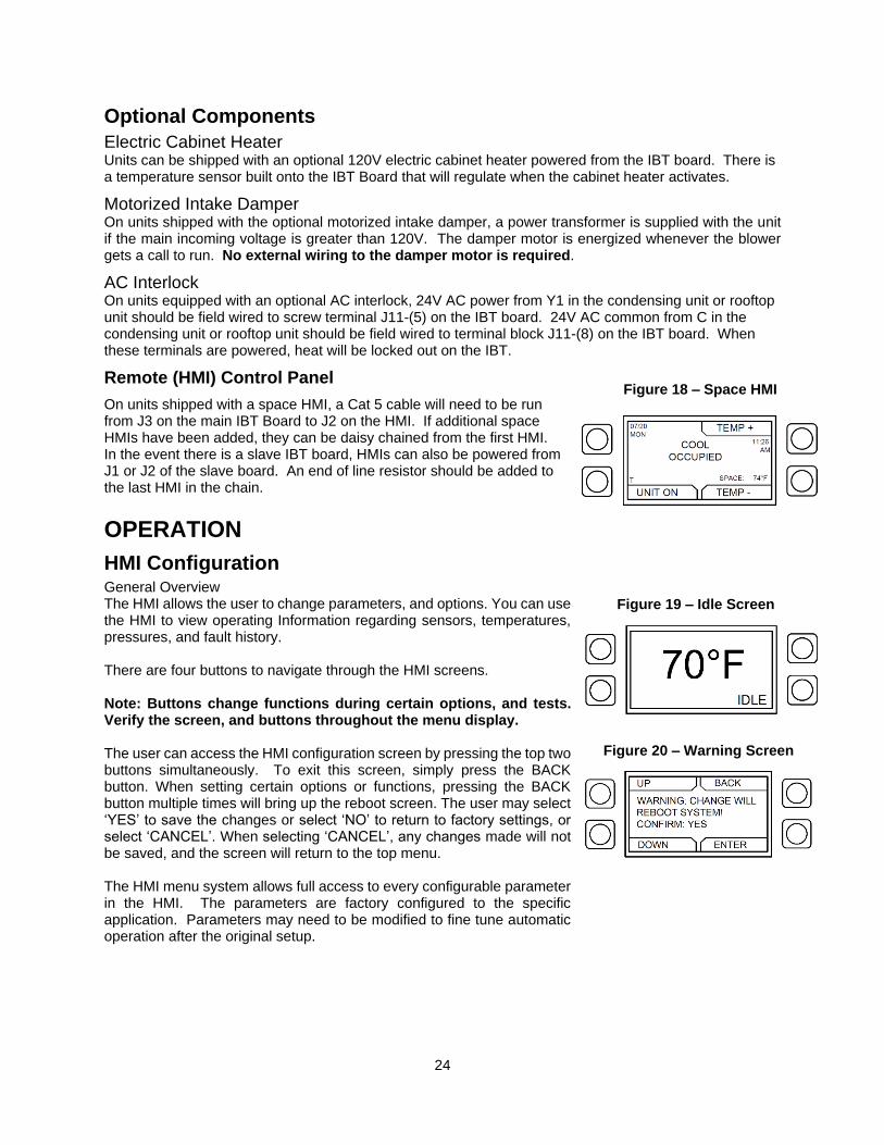
Optional Components
Electric Cabinet Heater Units can be shipped with an optional 120V electric cabinet heater powered from the IBT board. There is a temperature sensor built onto the IBT Board that will regulate when the cabinet heater activates.
Motorized Intake Damper On units shipped with the optional motorized intake damper, a power transformer is supplied with the unit if the main incoming voltage is greater than 120V. The damper motor is energized whenever the blower gets a call to run. No external wiring to the damper motor is required.
AC Interlock On units equipped with an optional AC interlock, 24V AC power from Y1 in the condensing unit or rooftop unit should be field wired to screw terminal J11-(5) on the IBT board. 24V AC common from C in the condensing unit or rooftop unit should be field wired to terminal block J11-(8) on the IBT board. When these terminals are powered, heat will be locked out on the IBT.
Remote (HMI) Control Panel
On units shipped with a space HMI, a Cat 5 cable will need to be run from J3 on the main IBT Board to J2 on the HMI. If additional space HMIs have been added, they can be daisy chained from the first HMI. In the event there is a slave IBT board, HMIs can also be powered from J1 or J2 of the slave board. An end of line resistor should be added to the last HMI in the chain.
OPERATION
HMI Configuration General Overview The HMI allows the user to change parameters, and options. You can use the HMI to view operating Information regarding sensors, temperatures, pressures, and fault history.
There are four buttons to navigate through the HMI screens. Note: Buttons change functions during certain options, and tests. Verify the screen, and buttons throughout the menu display. The user can access the HMI configuration screen by pressing the top two buttons simultaneously. To exit this screen, simply press the BACK button. When setting certain options or functions, pressing the BACK button multiple times will bring up the reboot screen. The user may select ‘YES’ to save the changes or select ‘NO’ to return to factory settings, or select ‘CANCEL’. When selecting ‘CANCEL’, any changes made will not be saved, and the screen will return to the top menu. The HMI menu system allows full access to every configurable parameter in the HMI. The parameters are factory configured to the specific application. Parameters may need to be modified to fine tune automatic operation after the original setup.
Figure 20 – Warning Screen
Figure 18 – Space HMI
Figure 19 – Idle Screen

25
HMI Options Screen
To set the HMI number or to adjust the screen contrast, press the bottom two buttons simultaneously on the HMI faceplate. Use the UP and Down buttons to select the parameter that will be adjusted. Press Enter to select the highlighted parameter. Setting the HMI number configures the Modbus address for that HMI. To change the contrast, select “Advanced Options”. The user may adjust the setting from 0 to 10. Setting the contrast to 0 is the lowest setting available and 10 is the highest contrast setting available. The factory default contrast setting is 5. HMI Notification Letters The HMI will display notification letters when the unit is in a specific status.
• When the blower is in a delay, a “B” will be displayed.
• When the condensers are in a Min ON or Min OFF time, a “T” will be displayed.
HMI Menu Description
(Any changes within this menu do not require a reboot to take effect)
• Temp Set Points – Some of these may not be available based on settings. If scheduling is enabled there will be both occupied and unoccupied values for each set point.
• Scheduling – This menu will only show when scheduling option has been turned on. Each day contains the option for two occupied time periods. If the time is scrolled past 11:59pm it will display UNOCC.
• Copy Schedule – This will allow the user to copy an existing schedule from one day of the week to individual days in the week, to Week Days, or ALL.
• Fan Speed - Enabled when blower control is set to VFD Manual. The range of this menu is limited by the min and max frequency set points under factory settings. When occupied scheduling is set to on, occupied and unoccupied settings are available.
• HMI Dimming Timer - Configurable menu time until dim, 10 seconds - 60 seconds.
• PWM Rate - Enabled when blower control is set to ECM. This will be used to control the speed of the ECM motor. The PWM signal will be sent directly to the ECM motor. When occupied scheduling is set to on, occupied and unoccupied settings are available.
• Mixing Box Voltage - Enabled when ‘Mixing Box Config’ is set to ‘Manual’. Voltage output to air box damper.
• Outdoor Air % - Enabled when ‘Mixing Box Config’ is set to ‘Schedule’, or ‘Outdoor Air %’. Limited by min and max outdoor air percentages in factory settings. When occupied scheduling is set to on, occupied and unoccupied settings are available.
• Active Faults – Contains the current faults on the board
• Fault History - Will show time stamped history of the last 20 faults, most recent fault showing
first.
• Reset Fault Lockout – Resets lock out faults.
Figure 21 – Notification Letters
USER SETTINGS
26
(Password = 1111)
(These will be set job specific from the plant. Any changes within this menu require a reboot to take effect. Upon exiting factory settings, if anything has been altered, the board will reboot itself. Password = 1111. There is a 5 minute timer before having to re-enter password.)
• Temperature Control - If scheduling is enabled there will be both occupied and unoccupied values for each set point. ▪ Tempering Mode Heat – Discharge, Space, Analog Control, DDC, None. ▪ Tempering Mode Cool – Intake, Space, Analog Control, DDC, None. ▪ Activate Based On – Intake, Space, Both, Either, Stat. Default is Either.
• Heating Config ▪ # Of Heat Stages – 0, 1, 2, 3, 4 heat stages. ▪ Intake Heat Hysteresis (Hyst) – Intake sensor must go this amount of degrees above the set
point before heating will turn off. ▪ Space Heat Hysteresis (Hyst) – Space sensor must go this amount of degrees above the set
point before heating will turn off. ▪ Heater Firing Order – Standard, alternate. Standard firing order is furnace 1, 2, 3, 4.
Alternate firing order is furnace 2, 1, 3, 4. This option has no effect for single furnace units. ▪ Input Source – 0-10V DC, 2-10V DC, 0-20 mA, 4-20 mA. This lets the board know what
signal to expect from an Analog Control system. ▪ Cabinet Diff – This is the differential for the cabinet heater. The outdoor air temp must fall
this many degrees below the activation set point to turn off. ▪ Freezestat Timer – The discharge temp must stay below the freezestat set point for this
amount of time before the unit will lock out on freeze stat. ▪ ROT Delay – This is the time after a furnace loses a call for heat before the furnace shuts
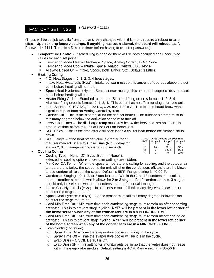
down. ▪ RCT Delays – If the heat stage value is greater than 1,
the user may adjust Relay Close Time (RCT) delay for stages 2, 3, 4. Range settings is 30-600 seconds.
• Cooling Config ▪ Cooling Type – None, DX, Evap, Both. If “None” is
selected all cooling options under user settings are hidden. ▪ Min Cool OA Temp – When the space temperature is calling for cooling, and the outdoor air
temperature is below the set point, the unit will shut the condensers off, and start the blower to use outdoor air to cool the space. Default is 55°F. Range setting is 40-90°F.
▪ Condenser Staging – 0, 1, 2, or 3 condensers. Within the 2 and 3 condenser selection, there is another submenu which allows for 2 or 3 stages. For 2 condenser units, 3 stages should only be selected when the condensers are of unequal tonnages.
▪ Intake Cool Hysteresis (Hyst) – Intake sensor must fall this many degrees below the set point for the stage to turn off.
▪ Space Cool Hysteresis (Hyst) – Space sensor must fall this many degrees below the set point for the stage to turn off.
▪ Cond Min Time On – Minimum time each condensing stage must remain on after becoming activated. This is to prevent stage cycling. A “T” will be present in the lower left corner of the home screen when any of the condensers are in a MIN ON/OFF TIME.
▪ Cond Min Time Off – Minimum time each condensing stage must remain off after being de-activated. This is to prevent stage cycling. A “T” will be present in the lower left corner of the home screen when any of the condensers are in a MIN ON/OFF TIME.
▪ Evap Config (continued) o Spray Time On – Time the evaporative cooler will spray in the cycle. o Spray Time Off – Time the evaporative cooler will be idle in the cycle. o Evap Drain – On/Off. Default is Off. o Evap Drain SP - This setting will monitor outside air so that the water does not freeze
within the evaporator module. Default setting is 40°F. Range setting is 35-50°F.
FACTORY SETTINGS
RCT Delay Defaults (in Seconds) RCT Stage 2 Stage 3 Stage 4
1 0 0 0 2 120 s 90 s 90 s 3 0 120 s 90 s 4 0 0 120 s
27
(Password = 1111)
▪ Evap Config (continued) o Drain Differential – Temperature differential setting before the drain shuts off. Default
setting is 2°F. Range setting is 1-5°F. o Evap Differential – Temperature differential before the evap cooling shuts off. Default
setting is 3°F. Range setting is 1-10°F.
• Occupied Scheduling – This menu is where the scheduling can be turned On or Off. Default is Off.
• Occupancy Override – This menu is where the occupancy override can be turned On or Off. Default is On.
• Unit Options ▪ Board Config
o IBT Address – Modbus address of the IBT board. o Startup Timer – Time upon power up where the board will sit idle. o Celsius/Fahrenheit – Celsius, Fahrenheit. Changing between the two will reset all set
points. o # of HMIs – Number of HMIs connected to the IBT board. Must always be at least one. o HMI Averaging – If there are multiple space HMIs connected, this menu allows you to
select which will be included in the space averaging. If a thermistor is connected into the ST screw terminals, it will automatically be averaged into any HMIs included.
o HMI Dimming – This is an On/Off menu. Default is set to Off. If set to On, a ‘HMI Dimming Timer’ option will be available under ‘User Settings’.
o Screensaver - This is an On/Off menu. Default is set to On. If set to Off, the home screen will not time out to the screensaver.
▪ Blower Config o Blower Control – 120V Contactor, VFD Manual, VFD Jog, VFD 0-10V, ECM, ECM 0-
10V. ➢ 120V Contactor – 120V output on the IBT board to drive the coil of a contactor. This
option should be selected when the IBT is used in conjunction with a DCV package. ➢ VFD Manual – HMI selectable VFD frequency.
➢ VFD Jog – For use with VFD using photohelic control. Uses the aux pins to control the VFD. Powering aux 1 will speed the fan up, powering aux 2 will slow the fan down. When aux 1 or aux 2 are not powered, the VFD will hold current speed.
➢ VFD 0-10V – For use when an external 0-10V signal is being provided to control the speed of the VFD. The VFD output from this input will be based on the VFD min and max freq set under protected params in factory settings. 0 Volts will equal VFD min, 10V will equal VFD max, and all voltages in between will be scaled linearly. This option will utilize 0-10V J14-(6) and 0-10V common J14-(7) screw terminals and will require field wiring.
➢ Electronically Controlled Motor (ECM) - HMI selectable PWM rate. ➢ ECM 0-10V - For use when an external 0-10V signal is being provided to modulate
the ECM supply output between min and max speed. o Blower Mode – If the Occupied Scheduling is set to ON, the menu screen for the blower
mode will allow you to choose ON/AUTO/OFF for Occupied or Unoccupied. If the Occupied Scheduling is set to OFF, the menu screen for the blower mode will allow you to choose MANUAL/AUTO/OFF. In blower auto mode, the blower will only run when it gets a call for heating/cooling. In blower manual mode, the blower will run as long as the fan button is enabled regardless of whether the unit is heating/cooling. In blower off mode, powering the unit interlock pin will cause the blower to run. This setting should be used when an IBT is covered by a prewire package.
FACTORY SETTINGS
28
(Password = 1111)
o Blower Start Delay – On, Off. Enabling this menu will run the furnace before starting the blower. A “B” will be present in the lower-left corner when the unit is in a blower START/STOP DELAY.
o Blower Stop Delay – On, Off. Enabling this menu will stop the furnace and allow the blower to run until timer expires. A “B” will be present in the lower-left corner when the unit is in a blower START/STOP DELAY.
o Blower Delay Time – This sets the time that the furnace will run before the blower starts.
o Blower Preset Speed – This allows the user to set blower preset option On or Off.
o VFD Direction – Sends a command to the VFD to run in forward or reverse.
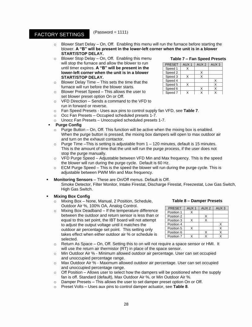
o Fan Speed Presets - Uses aux pins to control supply fan VFD, see Table 7. o Occ Fan Presets – Occupied scheduled presets 1-7. o Unocc Fan Presets – Unoccupied scheduled presets 1-7.
▪ Purge Config o Purge Button – On, Off. This function will be active when the mixing box is enabled.
When the purge button is pressed, the mixing box dampers will open to max outdoor air and turn on the exhaust contactor.
o Purge Time –This is setting is adjustable from 1 – 120 minutes, default is 15 minutes. This is the amount of time that the unit will run the purge process, if the user does not stop the purge manually.
o VFD Purge Speed – Adjustable between VFD Min and Max frequency. This is the speed the blower will run during the purge cycle. Default is 60 Hz.
o ECM Purge Speed – This is the speed the blower will run during the purge cycle. This is adjustable between PWM Min and Max frequency.
▪ Monitoring Sensors – These are On/Off menus. Default is Off. Smoke Detector, Filter Monitor, Intake Firestat, Discharge Firestat, Freezestat, Low Gas Switch, High Gas Switch.
▪ Mixing Box Config o Mixing Box – None, Manual, 2 Position, Schedule,
Outdoor Air %, 100% OA, Analog Control. o Mixing Box Deadband – If the temperature difference
between the outdoor and return sensor is less than or equal to this set point, the IBT board will not attempt to adjust the output voltage until it matches the outdoor air percentage set point. This setting only takes effect when either outdoor air % or schedule is selected.
o Return As Space – On, Off. Setting this to on will not require a space sensor or HMI. It will use the return air thermistor (RT) in place of the space sensor.
o Min Outdoor Air % - Minimum allowed outdoor air percentage. User can set occupied and unoccupied percentage range.
o Max Outdoor Air % - Maximum allowed outdoor air percentage. User can set occupied and unoccupied percentage range.
o Off Position – Allows user to select how the dampers will be positioned when the supply fan is off. Standard (default), Max Outdoor Air %, or Min Outdoor Air %.
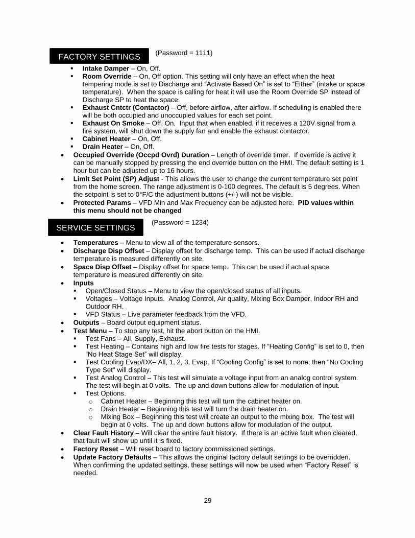
o Damper Presets – This allows the user to set damper preset option On or Off. o Preset Volts – Uses aux pins to control damper actuator, see Table 8.
PRESET AUX 1 AUX 2 AUX 3
Speed 1 X
Speed 2 X
Speed 3 X X
Speed 4 X
Speed 5 X X
Speed 6 X X
Speed 7 X X X
FACTORY SETTINGS
Table 7 – Fan Speed Presets
PRESET AUX 1 AUX 2 AUX 3
Position 1 X
Position 2 X
Position 3 X X
Position 4 X
Position 5 X X
Position 6 X X
Position 7 X X X
Table 8 – Damper Presets
29
(Password = 1111)
▪ Intake Damper – On, Off. ▪ Room Override – On, Off option. This setting will only have an effect when the heat
tempering mode is set to Discharge and “Activate Based On” is set to “Either” (intake or space temperature). When the space is calling for heat it will use the Room Override SP instead of Discharge SP to heat the space.
▪ Exhaust Cntctr (Contactor) – Off, before airflow, after airflow. If scheduling is enabled there will be both occupied and unoccupied values for each set point.
▪ Exhaust On Smoke – Off, On. Input that when enabled, if it receives a 120V signal from a fire system, will shut down the supply fan and enable the exhaust contactor.
▪ Cabinet Heater – On, Off. ▪ Drain Heater – On, Off.
• Occupied Override (Occpd Ovrd) Duration – Length of override timer. If override is active it can be manually stopped by pressing the end override button on the HMI. The default setting is 1 hour but can be adjusted up to 16 hours.
• Limit Set Point (SP) Adjust - This allows the user to change the current temperature set point from the home screen. The range adjustment is 0-100 degrees. The default is 5 degrees. When the setpoint is set to 0°F/C the adjustment buttons (+/-) will not be visible.
• Protected Params – VFD Min and Max Frequency can be adjusted here. PID values within this menu should not be changed
(Password = 1234)
• Temperatures – Menu to view all of the temperature sensors. • Discharge Disp Offset – Display offset for discharge temp. This can be used if actual discharge
temperature is measured differently on site.
• Space Disp Offset – Display offset for space temp. This can be used if actual space temperature is measured differently on site.
• Inputs ▪ Open/Closed Status – Menu to view the open/closed status of all inputs. ▪ Voltages – Voltage Inputs. Analog Control, Air quality, Mixing Box Damper, Indoor RH and
Outdoor RH. ▪ VFD Status – Live parameter feedback from the VFD.
• Outputs – Board output equipment status.
• Test Menu – To stop any test, hit the abort button on the HMI. ▪ Test Fans – All, Supply, Exhaust. ▪ Test Heating – Contains high and low fire tests for stages. If “Heating Config” is set to 0, then
“No Heat Stage Set” will display. ▪ Test Cooling Evap/DX– All, 1, 2, 3, Evap. If “Cooling Config” is set to none, then "No Cooling
Type Set" will display. ▪ Test Analog Control – This test will simulate a voltage input from an analog control system.
The test will begin at 0 volts. The up and down buttons allow for modulation of input. ▪ Test Options.
o Cabinet Heater – Beginning this test will turn the cabinet heater on. o Drain Heater – Beginning this test will turn the drain heater on. o Mixing Box – Beginning this test will create an output to the mixing box. The test will
begin at 0 volts. The up and down buttons allow for modulation of the output.
• Clear Fault History – Will clear the entire fault history. If there is an active fault when cleared, that fault will show up until it is fixed.
• Factory Reset – Will reset board to factory commissioned settings.
• Update Factory Defaults – This allows the original factory default settings to be overridden. When confirming the updated settings, these settings will now be used when “Factory Reset” is needed.
FACTORY SETTINGS
SERVICE SETTINGS
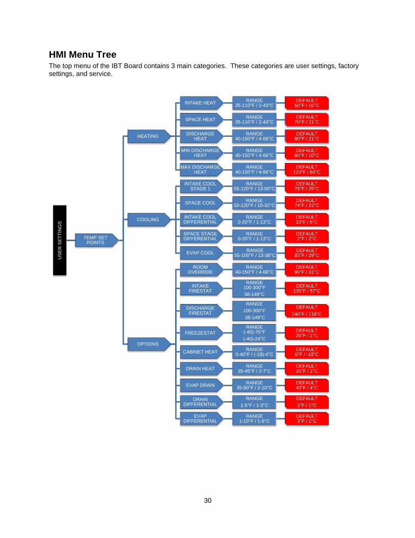
30
HMI Menu Tree
The top menu of the IBT Board contains 3 main categories. These categories are user settings, factory settings, and service.
US
ER
SE
TT
ING
S
TEMP SET POINTS
HEATING
INTAKE HEATRANGE
35-110°F / 2-43°CDEFAULT
60°F / 16°C
SPACE HEATRANGE
35-110°F / 2-43°CDEFAULT
70°F / 21°C
DISCHARGE HEAT
RANGE40-150°F / 4-66°C
DEFAULT80°F / 21°C
MIN DISCHARGE HEAT
RANGE40-150°F / 4-66°C
DEFAULT80°F / 10°C
MAX DISCHARGE HEAT
RANGE40-150°F / 4-66°C
DEFAULT120°F / 66°C
COOLING
INTAKE COOL STAGE 1
RANGE55-120°F / 13-50°C
DEFAULT 75°F / 29°C
SPACE COOLRANGE
50-120°F / 10-32°CDEFAULT
74°F / 23°C
INTAKE COOL DIFFERENTIAL
RANGE0-20°F / 1-13°C
DEFAULT10°F / 6°C
SPACE STAGE DIFFERENTIAL
RANGE0-20°F / 1-13°C
DEFAULT2°F / 2°C
EVAP COOLRANGE
55-100°F / 13-38°CDEFAULT
85°F / 29°C
OPTIONS
ROOM OVERRIDE
RANGE40-150°F / 4-66°C
DEFAULT 90°F / 31°C
INTAKE FIRESTAT
RANGE100-300°F
38-149°C
DEFAULT 135°F / 57°C
DISCHARGE FIRESTAT
RANGE
100-300°F
38-149°C
DEFAULT
240°F / 116°C
FREEZESTAT
RANGE(-40)-75°F
(-40)-24°C
DEFAULT 35°F / 2°C
CABINET HEATRANGE
0-40°F / (-18)-4°CDEFAULT0°F / -18°C
DRAIN HEATRANGE
35-45°F / 2-7°CDEFAULT 35°F / 2°C
EVAP DRAINRANGE
35-50°F / 2-10°CDEFAULT40°F / 4°C
DRAIN DIFFERENTIAL
RANGE
1-5°F / 1-3°C
DEFAULT
2°F / 1°C
EVAP DIFFERENTIAL
RANGE1-10°F / 1-6°C
DEFAULT3°F / 2°C
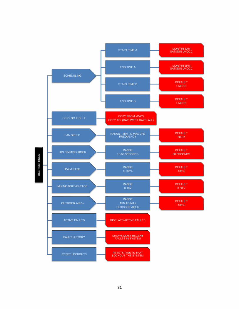
31
US
ER
SE
TT
ING
S
SCHEDULING
START TIME AMON/FRI 8AM
SAT/SUN UNOCC
END TIME AMON/FRI 6PM
SAT/SUN UNOCC
START TIME BDEFAULT
UNOCC
END TIME BDEFAULT
UNOCC
COPY SCHEDULECOPY FROM: (DAY)
COPY TO: (DAY, WEEK DAYS, ALL)
FAN SPEEDRANGE - MIN TO MAX VFD
FREQUENCY
DEFAULT
60 HZ
HMI DIMMING TIMERRANGE
10-60 SECONDS
DEFAULT
60 SECONDS
PWM RATERANGE
0-100%
DEFAULT
100%
MIXING BOX VOLTAGERANGE
0-10V
DEFAULT
0.00 V
OUTDOOR AIR %
RANGE
MIN TO MAX
OUTDOOR AIR %
DEFAULT
100%
ACTIVE FAULTS DISPLAYS ACTIVE FAULTS
FAULT HISTORYSHOWS MOST RECENT
FAULTS IN SYSTEM
RESET LOCKOUTSRESETS FAULTS THAT LOCKOUT THE SYSTEM
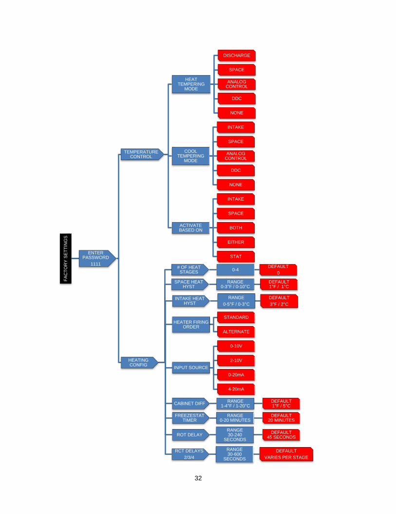
32
FA
CT
OR
Y S
ET
TIN
GS
ENTER PASSWORD
1111
TEMPERATURE CONTROL
HEAT TEMPERING
MODE
DISCHARGE
SPACE
ANALOG CONTROL
DDC
NONE
COOL TEMPERING
MODE
INTAKE
SPACE
ANALOG CONTROL
DDC
NONE
ACTIVATE BASED ON
INTAKE
SPACE
BOTH
EITHER
STAT
HEATING CONFIG
# OF HEAT STAGES
0-4DEFAULT
0
INTAKE HEAT HYST
RANGE
0-5°F / 0-3°C
DEFAULT
3°F / 2°C
SPACE HEAT HYST
RANGE0-3°F / 0-10°C
DEFAULT1°F / 1°C
HEATER FIRING ORDER
STANDARD
ALTERNATE
INPUT SOURCE
0-10V
2-10V
0-20mA
4-20mA
CABINET DIFFRANGE
1-4°F / 1-20°CDEFAULT1°F / 5°C
FREEZESTAT TIMER
RANGE0-20 MINUTES
DEFAULT20 MINUTES
ROT DELAYRANGE30-240
SECONDS
DEFAULT45 SECONDS
RCT DELAYS
2/3/4
RANGE 30-600
SECONDS
DEFAULT
VARIES PER STAGE
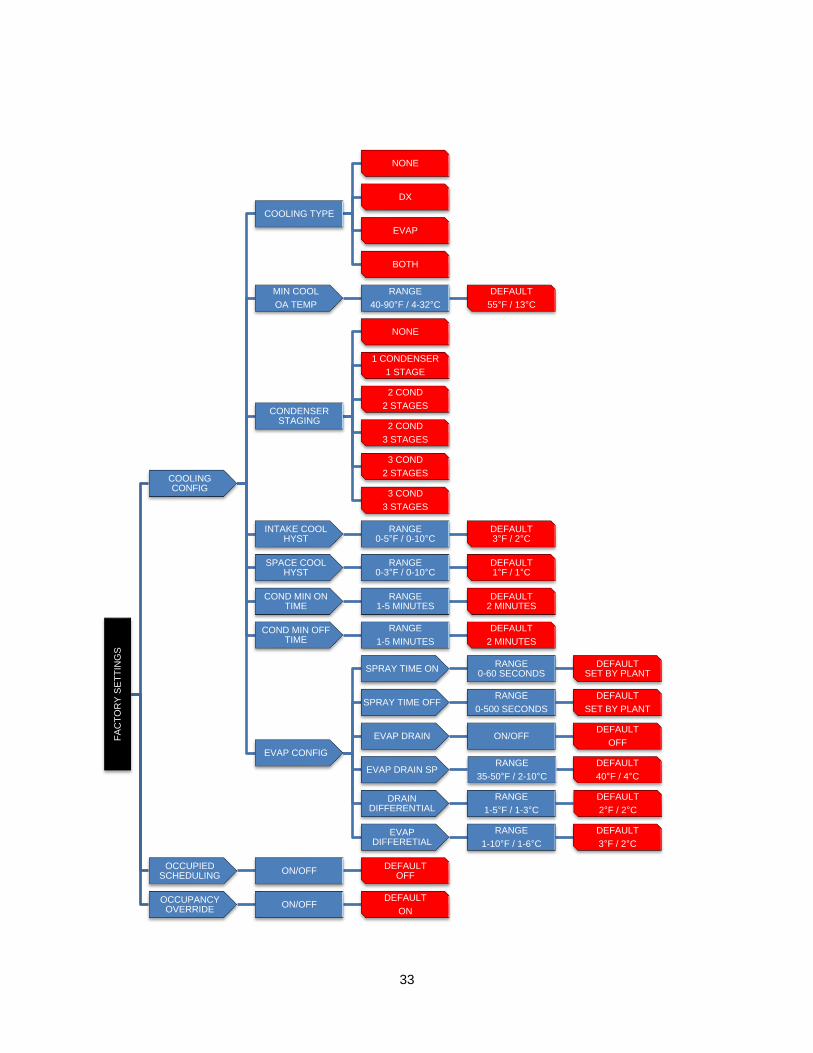
33
FA
CT
OR
Y S
ET
TIN
GS
COOLING CONFIG
COOLING TYPE
NONE
DX
EVAP
BOTH
MIN COOL
OA TEMP
RANGE
40-90°F / 4-32°C
DEFAULT
55°F / 13°C
CONDENSER STAGING
NONE
1 CONDENSER
1 STAGE
2 COND
2 STAGES
2 COND
3 STAGES
3 COND
2 STAGES
3 COND
3 STAGES
INTAKE COOL HYST
RANGE0-5°F / 0-10°C
DEFAULT3°F / 2°C
SPACE COOL HYST
RANGE0-3°F / 0-10°C
DEFAULT1°F / 1°C
COND MIN ON TIME
RANGE1-5 MINUTES
DEFAULT2 MINUTES
COND MIN OFF TIME
RANGE
1-5 MINUTES
DEFAULT
2 MINUTES
EVAP CONFIG
SPRAY TIME ONRANGE
0-60 SECONDSDEFAULT
SET BY PLANT
SPRAY TIME OFFRANGE
0-500 SECONDS
DEFAULT
SET BY PLANT
EVAP DRAIN ON/OFFDEFAULT
OFF
EVAP DRAIN SPRANGE
35-50°F / 2-10°C
DEFAULT
40°F / 4°C
DRAIN DIFFERENTIAL
RANGE
1-5°F / 1-3°C
DEFAULT
2°F / 2°C
EVAP DIFFERETIAL
RANGE
1-10°F / 1-6°C
DEFAULT
3°F / 2°C
OCCUPIED SCHEDULING
ON/OFFDEFAULT
OFF
OCCUPANCY OVERRIDE
ON/OFFDEFAULT
ON
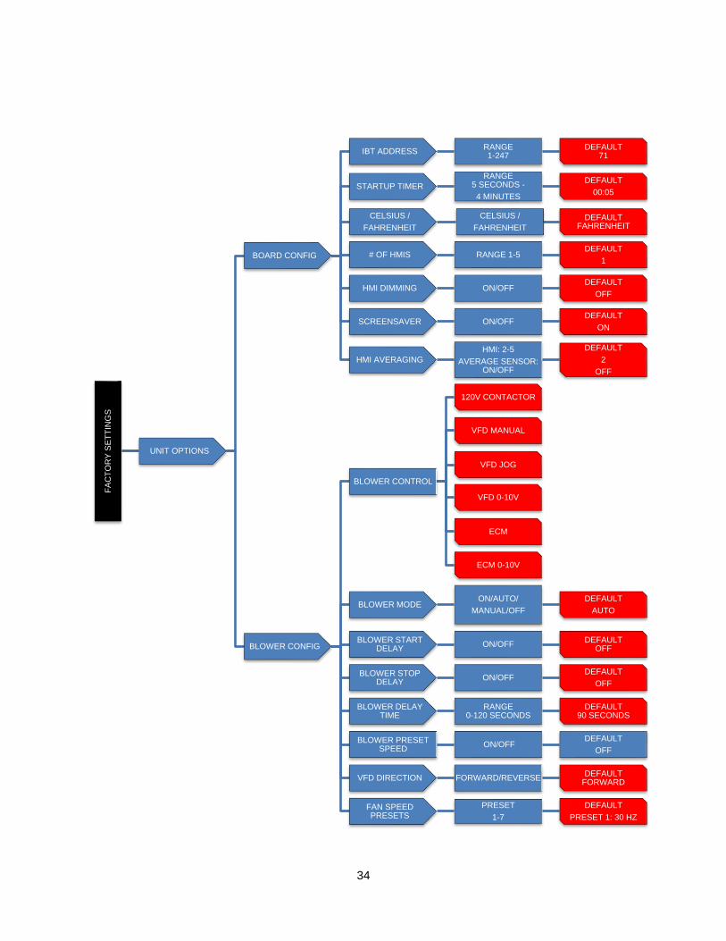
34
FA
CT
OR
Y S
ET
TIN
GS
UNIT OPTIONS
BOARD CONFIG
IBT ADDRESSRANGE1-247
DEFAULT71
STARTUP TIMER
RANGE5 SECONDS -
4 MINUTES
DEFAULT
00:05
CELSIUS /
FAHRENHEIT
CELSIUS /
FAHRENHEIT
DEFAULTFAHRENHEIT
# OF HMIS RANGE 1-5DEFAULT
1
HMI DIMMING ON/OFFDEFAULT
OFF
SCREENSAVER ON/OFFDEFAULT
ON
HMI AVERAGING
HMI: 2-5
AVERAGE SENSOR: ON/OFF
DEFAULT
2
OFF
BLOWER CONFIG
BLOWER CONTROL
120V CONTACTOR
VFD MANUAL
VFD JOG
VFD 0-10V
ECM
ECM 0-10V
BLOWER MODEON/AUTO/
MANUAL/OFF
DEFAULT
AUTO
BLOWER START DELAY
ON/OFFDEFAULT
OFF
BLOWER STOP DELAY
ON/OFFDEFAULT
OFF
BLOWER DELAY TIME
RANGE0-120 SECONDS
DEFAULT90 SECONDS
BLOWER PRESET SPEED
ON/OFFDEFAULT
OFF
VFD DIRECTION FORWARD/REVERSEDEFAULT
FORWARD
FAN SPEED PRESETS
PRESET
1-7
DEFAULT
PRESET 1: 30 HZ
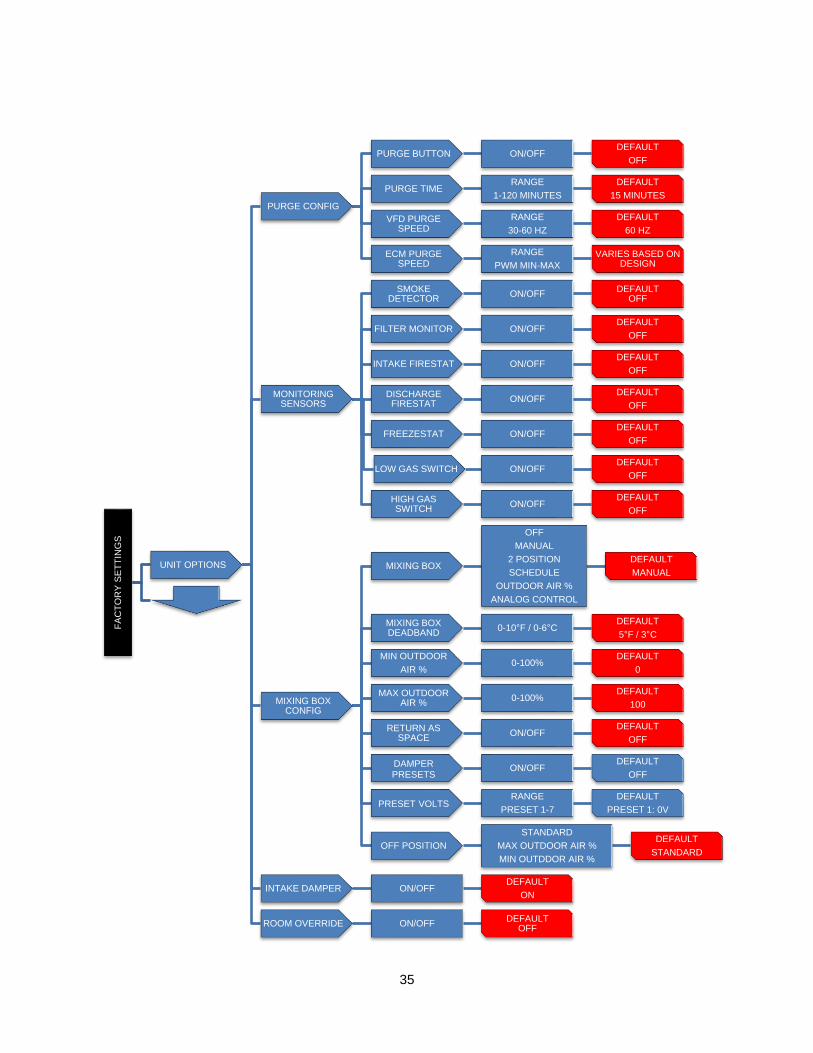
35
FA
CT
OR
Y S
ET
TIN
GS
UNIT OPTIONS
PURGE CONFIG
PURGE BUTTON ON/OFFDEFAULT
OFF
PURGE TIMERANGE
1-120 MINUTES
DEFAULT
15 MINUTES
VFD PURGE SPEED
RANGE
30-60 HZ
DEFAULT
60 HZ
ECM PURGE SPEED
RANGE
PWM MIN-MAX
VARIES BASED ON DESIGN
MONITORING SENSORS
SMOKE DETECTOR
ON/OFFDEFAULT
OFF
FILTER MONITOR ON/OFFDEFAULT
OFF
INTAKE FIRESTAT ON/OFFDEFAULT
OFF
DISCHARGE FIRESTAT
ON/OFFDEFAULT
OFF
FREEZESTAT ON/OFFDEFAULT
OFF
LOW GAS SWITCH ON/OFFDEFAULT
OFF
HIGH GAS SWITCH
ON/OFFDEFAULT
OFF
MIXING BOX CONFIG
MIXING BOX
OFF
MANUAL
2 POSITION
SCHEDULE
OUTDOOR AIR %
ANALOG CONTROL
DEFAULT
MANUAL
MIXING BOX DEADBAND
0-10°F / 0-6°CDEFAULT
5°F / 3°C
MIN OUTDOOR
AIR %0-100%
DEFAULT
0
MAX OUTDOOR AIR %
0-100%DEFAULT
100
RETURN AS SPACE
ON/OFFDEFAULT
OFF
DAMPERPRESETS
ON/OFFDEFAULT
OFF
PRESET VOLTSRANGE
PRESET 1-7
DEFAULT
PRESET 1: 0V
OFF POSITION
STANDARD
MAX OUTDOOR AIR %
MIN OUTDDOR AIR %
DEFAULT
STANDARD
INTAKE DAMPER ON/OFFDEFAULT
ON
ROOM OVERRIDE ON/OFFDEFAULT
OFF
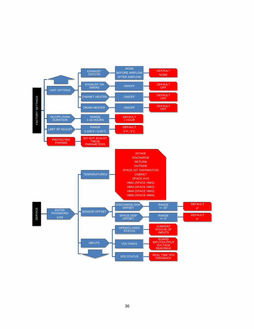
36
FA
CT
OR
Y S
ET
TIN
GS
UNIT OPTIONS
EXHAUST CNTCTR
NONE
BEFORE AIRFLOW
AFTER AIRFLOW
DEFAULT
NONE
EXHAUST ON SMOKE
ON/OFFDEFAULT
OFF
CABINET HEATER ON/OFFDEFAULT
OFF
DRAIN HEATER ON/OFFDEFAULT
OFF
OCCPD OVRD DURATION
RANGE1-16 HOURS
DEFAULT1 HOUR
LIMIT SP ADJUSTRANGE
0-100°F / 0-55°C
DEFAULT
5°F / 3°C
PROTECTED PARAMS
DO NOT ADJUST THESE
PARAMETERS
SE
RV
ICE
ENTER PASSWORD
1234
TEMPERATURES
INTAKE
DISCHARGE
RETURN
OUTSIDE
SPACE (ST THERMISTOR)
CABINET
SPACE AVG
HMI2 (SPACE HMI1)
HMI3 (SPACE HMI2)
HMI4 (SPACE HMI3)
HMI5 (SPACE HMI4)
SENSOR OFFSET
DISCHARGE DISP OFFSET
RANGE+/- 20°
DEFAULT
0°
SPACE DISP OFFSET
RANGE+/- 5°
DEFAULT
0°
INPUTS
OPEN/CLOSED STATUS
CURRENT STATUS OF
INPUTS
VOLTAGES
BOARD INPUT/OUTPUT
VOLTAGE READINGS
VFD STATUSREAL TIME VFD
FEEDBACK
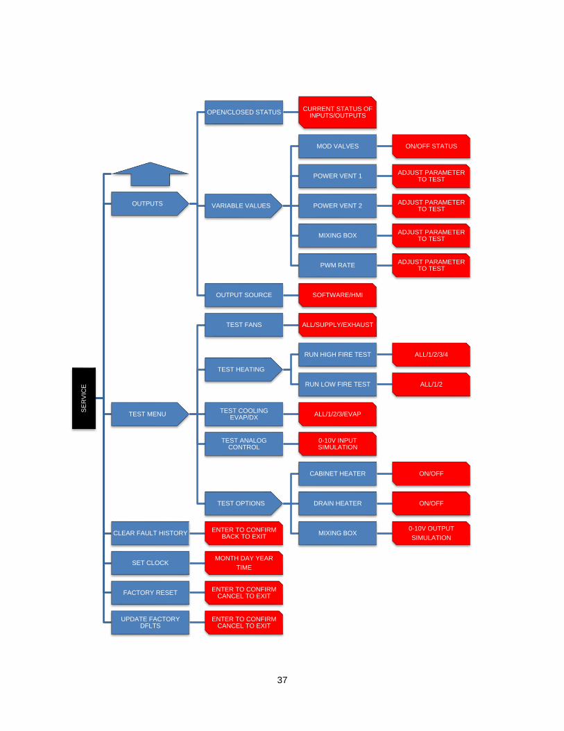
37
SE
RV
ICE
OUTPUTS
OPEN/CLOSED STATUSCURRENT STATUS OF
INPUTS/OUTPUTS
VARIABLE VALUES
MOD VALVES ON/OFF STATUS
POWER VENT 1ADJUST PARAMETER
TO TEST
POWER VENT 2ADJUST PARAMETER
TO TEST
MIXING BOXADJUST PARAMETER
TO TEST
PWM RATEADJUST PARAMETER
TO TEST
OUTPUT SOURCE SOFTWARE/HMI
TEST MENU
TEST FANS ALL/SUPPLY/EXHAUST
TEST HEATING
RUN HIGH FIRE TEST ALL/1/2/3/4
RUN LOW FIRE TEST ALL/1/2
TEST COOLING EVAP/DX
ALL/1/2/3/EVAP
TEST ANALOG CONTROL
0-10V INPUT SIMULATION
TEST OPTIONS
CABINET HEATER ON/OFF
DRAIN HEATER ON/OFF
MIXING BOX0-10V OUTPUT
SIMULATIONCLEAR FAULT HISTORY
ENTER TO CONFIRMBACK TO EXIT
SET CLOCK MONTH DAY YEAR
TIME
FACTORY RESETENTER TO CONFIRM
CANCEL TO EXIT
UPDATE FACTORY DFLTS
ENTER TO CONFIRMCANCEL TO EXIT
38
Start Up Prior to starting up or operating the heater, check all fasteners for tightness. In particular, check the set screw in the wheel hub, bearings, and the fan sheaves (pulleys). With power and gas to the heater OFF or prior to connecting ventilator to power, turn the fan wheel by hand to be sure it is not striking the inlet or any obstacles. Re-center, if necessary.
Tools Required
• AC Voltage Meter
• Tachometer
• Standard hand Tools
• Amperage Meter
• Manometer
• Thermometer
Start Up Procedure
1. Check all electrical connections for tightness and continuity.
2. Check pulley alignment and belt tension as shown in Pulley Alignment/Proper Belt Tension (page 44).
3. Inspect the condition of the intake damper and damper linkage, if provided.
4. Inspect the air-stream for obstructions and install intake filters if missing.
5. Compare the supplied motor voltage with the fan’s nameplate motor voltage. If this does not match, correct the problem.
6. Start the fan up by turning the external disconnect to the ON position, and shut it OFF immediately. Check rotation of the wheel with the directional arrow on the blower scroll. Reversed rotation will result in poor air performance, motor overloading and possible burnout. For units equipped with a single-phase motor check the motor wiring diagram to change rotation. For 3-phase motors, any two power leads can be interchanged to reverse motor direction.
7. When the fan is started up, observe the operation and check for any unusual noises.
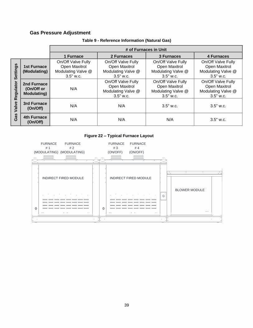
39
Gas Pressure Adjustment
Table 9 - Reference Information (Natural Gas)
# of Furnaces in Unit
1 Furnace 2 Furnaces 3 Furnaces 4 Furnaces
Ga
s V
alv
e R
eg
ula
tor
Se
ttin
gs
1st Furnace (Modulating)
On/Off Valve Fully Open Maxitrol
Modulating Valve @ 3.5" w.c.
On/Off Valve Fully Open Maxitrol
Modulating Valve @ 3.5" w.c.
On/Off Valve Fully Open Maxitrol
Modulating Valve @ 3.5" w.c.
On/Off Valve Fully Open Maxitrol
Modulating Valve @ 3.5" w.c.
2nd Furnace (On/Off or
Modulating) N/A
On/Off Valve Fully Open Maxitrol
Modulating Valve @ 3.5" w.c.
On/Off Valve Fully Open Maxitrol
Modulating Valve @ 3.5" w.c.
On/Off Valve Fully Open Maxitrol
Modulating Valve @ 3.5" w.c.
3rd Furnace (On/Off)
N/A N/A 3.5" w.c. 3.5" w.c.
4th Furnace (On/Off)
N/A N/A N/A 3.5" w.c.
BLOWER MODULE
FURNACE
# 3
(ON/OFF)(MODULATING)
# 2
FURNACE
INDIRECT FIRED MODULE
# 1
(MODULATING)
FURNACEFURNACE
INDIRECT FIRED MODULE
(ON/OFF)
# 4
Figure 22 – Typical Furnace Layout
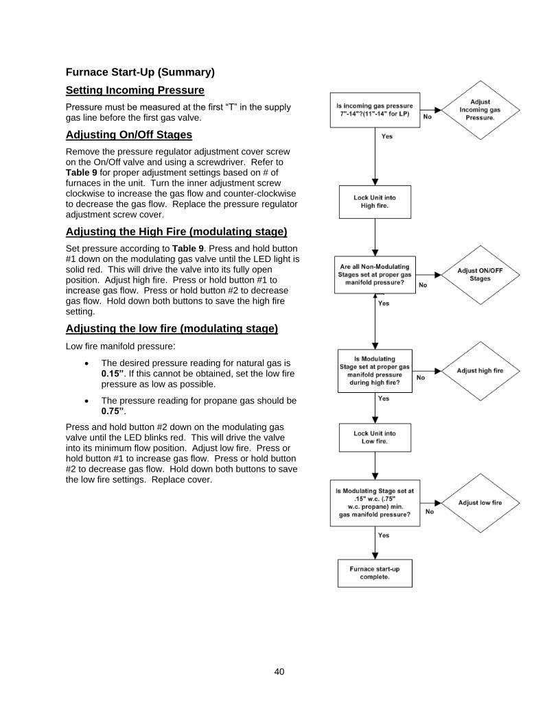
40
Furnace Start-Up (Summary)
Setting Incoming Pressure
Pressure must be measured at the first “T” in the supply gas line before the first gas valve.
Adjusting On/Off Stages
Remove the pressure regulator adjustment cover screw on the On/Off valve and using a screwdriver. Refer to Table 9 for proper adjustment settings based on # of furnaces in the unit. Turn the inner adjustment screw clockwise to increase the gas flow and counter-clockwise to decrease the gas flow. Replace the pressure regulator adjustment screw cover.
Adjusting the High Fire (modulating stage)
Set pressure according to Table 9. Press and hold button #1 down on the modulating gas valve until the LED light is solid red. This will drive the valve into its fully open position. Adjust high fire. Press or hold button #1 to increase gas flow. Press or hold button #2 to decrease gas flow. Hold down both buttons to save the high fire setting.
Adjusting the low fire (modulating stage)
Low fire manifold pressure:
• The desired pressure reading for natural gas is 0.15”. If this cannot be obtained, set the low fire pressure as low as possible.
• The pressure reading for propane gas should be 0.75”.
Press and hold button #2 down on the modulating gas valve until the LED blinks red. This will drive the valve into its minimum flow position. Adjust low fire. Press or hold button #1 to increase gas flow. Press or hold button #2 to decrease gas flow. Hold down both buttons to save the low fire settings. Replace cover.
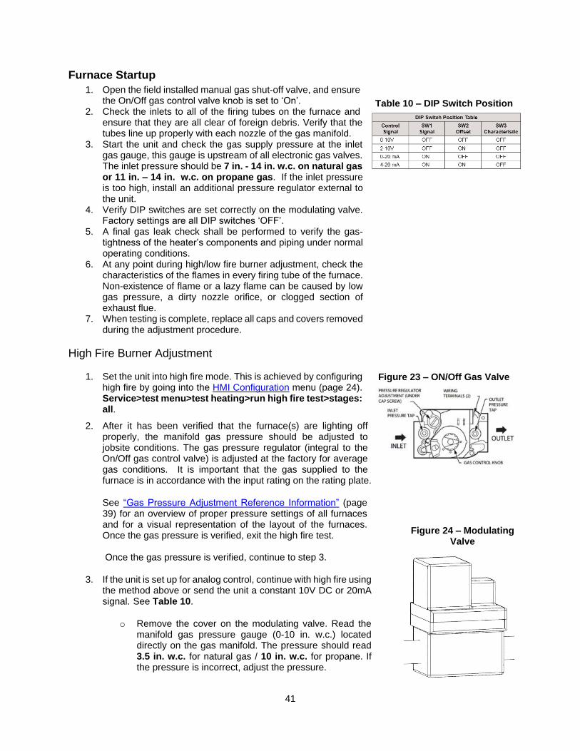
41
Furnace Startup
1. Open the field installed manual gas shut-off valve, and ensure the On/Off gas control valve knob is set to ‘On’.
2. Check the inlets to all of the firing tubes on the furnace and ensure that they are all clear of foreign debris. Verify that the tubes line up properly with each nozzle of the gas manifold.
3. Start the unit and check the gas supply pressure at the inlet gas gauge, this gauge is upstream of all electronic gas valves. The inlet pressure should be 7 in. - 14 in. w.c. on natural gas or 11 in. – 14 in. w.c. on propane gas. If the inlet pressure is too high, install an additional pressure regulator external to the unit.
4. Verify DIP switches are set correctly on the modulating valve. Factory settings are all DIP switches ‘OFF’.
5. A final gas leak check shall be performed to verify the gas-tightness of the heater’s components and piping under normal operating conditions.
6. At any point during high/low fire burner adjustment, check the characteristics of the flames in every firing tube of the furnace. Non-existence of flame or a lazy flame can be caused by low gas pressure, a dirty nozzle orifice, or clogged section of exhaust flue.
7. When testing is complete, replace all caps and covers removed during the adjustment procedure.
High Fire Burner Adjustment
1. Set the unit into high fire mode. This is achieved by configuring high fire by going into the HMI Configuration menu (page 24). Service>test menu>test heating>run high fire test>stages: all.
2. After it has been verified that the furnace(s) are lighting off properly, the manifold gas pressure should be adjusted to jobsite conditions. The gas pressure regulator (integral to the On/Off gas control valve) is adjusted at the factory for average gas conditions. It is important that the gas supplied to the furnace is in accordance with the input rating on the rating plate.
See “Gas Pressure Adjustment Reference Information” (page 39) for an overview of proper pressure settings of all furnaces and for a visual representation of the layout of the furnaces. Once the gas pressure is verified, exit the high fire test. Once the gas pressure is verified, continue to step 3.
3. If the unit is set up for analog control, continue with high fire using the method above or send the unit a constant 10V DC or 20mA signal. See Table 10.
o Remove the cover on the modulating valve. Read the manifold gas pressure gauge (0-10 in. w.c.) located directly on the gas manifold. The pressure should read 3.5 in. w.c. for natural gas / 10 in. w.c. for propane. If the pressure is incorrect, adjust the pressure.
Figure 23 – ON/Off Gas Valve
Table 10 – DIP Switch Position
Figure 24 – Modulating Valve
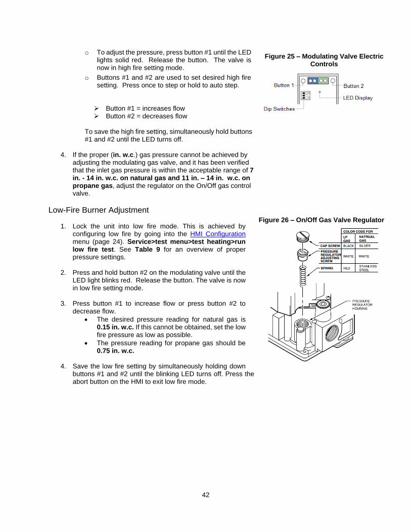
42
o To adjust the pressure, press button #1 until the LED lights solid red. Release the button. The valve is now in high fire setting mode.
o Buttons #1 and #2 are used to set desired high fire setting. Press once to step or hold to auto step. ➢ Button #1 = increases flow ➢ Button #2 = decreases flow
To save the high fire setting, simultaneously hold buttons #1 and #2 until the LED turns off.
4. If the proper (in. w.c.) gas pressure cannot be achieved by adjusting the modulating gas valve, and it has been verified that the inlet gas pressure is within the acceptable range of 7 in. - 14 in. w.c. on natural gas and 11 in. – 14 in. w.c. on propane gas, adjust the regulator on the On/Off gas control valve.
Low-Fire Burner Adjustment
1. Lock the unit into low fire mode. This is achieved by configuring low fire by going into the HMI Configuration menu (page 24). Service>test menu>test heating>run low fire test. See Table 9 for an overview of proper pressure settings.
2. Press and hold button #2 on the modulating valve until the LED light blinks red. Release the button. The valve is now in low fire setting mode.
3. Press button #1 to increase flow or press button #2 to decrease flow.
• The desired pressure reading for natural gas is 0.15 in. w.c. If this cannot be obtained, set the low fire pressure as low as possible.
• The pressure reading for propane gas should be 0.75 in. w.c.
4. Save the low fire setting by simultaneously holding down
buttons #1 and #2 until the blinking LED turns off. Press the abort button on the HMI to exit low fire mode.
Figure 25 – Modulating Valve Electric Controls
Figure 26 – On/Off Gas Valve Regulator
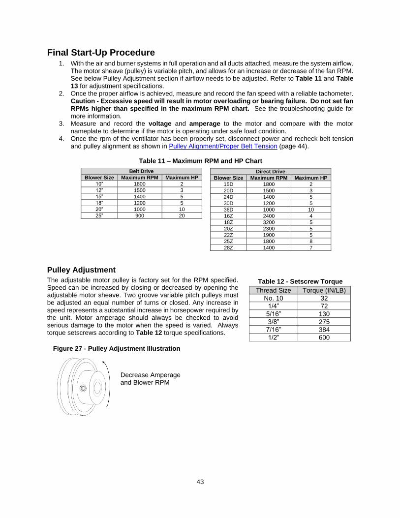
43
Table 11 – Maximum RPM and HP Chart
Final Start-Up Procedure 1. With the air and burner systems in full operation and all ducts attached, measure the system airflow.
The motor sheave (pulley) is variable pitch, and allows for an increase or decrease of the fan RPM. See below Pulley Adjustment section if airflow needs to be adjusted. Refer to Table 11 and Table 13 for adjustment specifications.
2. Once the proper airflow is achieved, measure and record the fan speed with a reliable tachometer. Caution - Excessive speed will result in motor overloading or bearing failure. Do not set fan RPMs higher than specified in the maximum RPM chart. See the troubleshooting guide for more information.
3. Measure and record the voltage and amperage to the motor and compare with the motor nameplate to determine if the motor is operating under safe load condition.
4. Once the rpm of the ventilator has been properly set, disconnect power and recheck belt tension and pulley alignment as shown in Pulley Alignment/Proper Belt Tension (page 44).
Pulley Adjustment
The adjustable motor pulley is factory set for the RPM specified. Speed can be increased by closing or decreased by opening the adjustable motor sheave. Two groove variable pitch pulleys must be adjusted an equal number of turns or closed. Any increase in speed represents a substantial increase in horsepower required by the unit. Motor amperage should always be checked to avoid serious damage to the motor when the speed is varied. Always torque setscrews according to Table 12 torque specifications.
Belt Drive
Blower Size Maximum RPM Maximum HP
10” 1800 2
12” 1500 3
15” 1400 5
18” 1200 5
20” 1000 10
25” 900 20
Direct Drive
Blower Size Maximum RPM Maximum HP
15D 1800 2
20D 1500 3
24D 1400 5
30D 1200 5
36D 1000 10
16Z 2400 4
18Z 3200 5
20Z 2300 5
22Z 1900 5
25Z 1800 8
28Z 1400 7
Table 12 - Setscrew Torque
Figure 27 - Pulley Adjustment Illustration
Decrease Amperage and Blower RPM
Thread Size Torque (IN/LB)
No. 10 32
1/4” 72
5/16” 130
3/8” 275
7/16” 384
1/2” 600
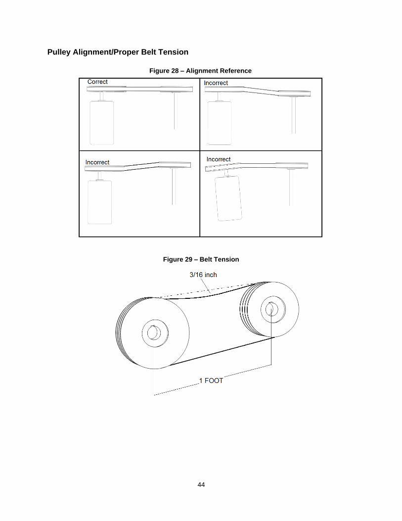
44
Pulley Alignment/Proper Belt Tension
Figure 28 – Alignment Reference
Figure 29 – Belt Tension
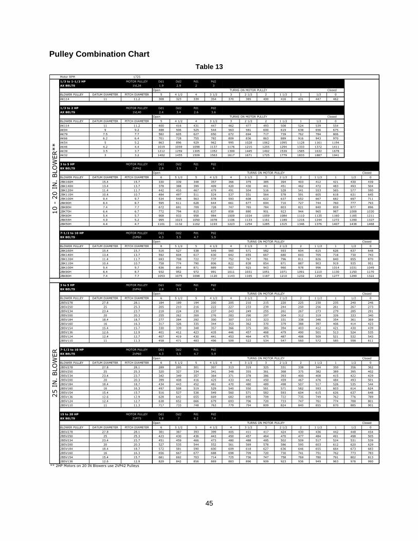
45
Pulley Combination Chart
Table 13
Motor RPM 1725
1/3 to 1-1/2 HP MOTOR PULLEY Dd1 Dd2 Pd1 Pd2
AX BELTS 1VL34 1.9 2.9 2 3
Open Closed
BLOWER PULLEY DATUM DIAMETER PITCH DIAMETER 5 4 1/2 4 3 1/2 3 2 1/2 2 1 1/2 1 1/2 0
AK114 11 11.2 308 323 339 354 370 385 400 416 431 447 462
1/3 to 2 HP MOTOR PULLEY Dd1 Dd2 Pd1 Pd2
AX BELTS 1VL40 2.4 3.4 2.6 3.6
Open Closed
BLOWER PULLEY DATUM DIAMETER PITCH DIAMETER 5 4 1/2 4 3 1/2 3 2 1/2 2 1 1/2 1 1/2 0
AK114 11 11.2 400 416 431 447 462 477 493 508 524 539 554
AK94 9 9.2 488 506 525 544 563 581 600 619 638 656 675
AK79 7.5 7.7 582 605 627 650 672 694 717 739 762 784 806
AK66 6.2 6.4 701 728 755 782 809 836 863 889 916 943 970
AK54 5 5.2 863 896 929 962 995 1028 1062 1095 1128 1161 1194
AK46 4.2 4.4 1019 1059 1098 1137 1176 1215 1255 1294 1333 1372 1411
AK39 3.5 3.7 1212 1259 1305 1352 1399 1445 1492 1539 1585 1632 1678
AK32 3 3.2 1402 1455 1509 1563 1617 1671 1725 1779 1833 1887 1941
3 to 5 HP MOTOR PULLEY Dd1 Dd2 Pd1 Pd2
BX BELTS 2VP42 2.9 3.9 3 4
Open Closed
BLOWER PULLEY DATUM DIAMETER PITCH DIAMETER 6 5 1/2 5 4 1/2 4 3 1/2 3 2 1/2 2 1 1/2 1 1/2 0
2BK160H 15.4 15.7 330 339 348 357 366 375 385 394 403 412 421 430 439
2BK140H 13.4 13.7 378 388 399 409 420 430 441 451 462 472 483 493 504
2BK120H 11.4 11.7 442 455 467 479 491 504 516 528 541 553 565 577 590
2BK110H 10.4 10.7 484 497 511 524 537 551 564 578 591 605 618 631 645
2BK100H 9.4 9.7 534 548 563 578 593 608 622 637 652 667 682 697 711
2BK90H 8.4 8.7 595 611 628 644 661 677 694 710 727 744 760 777 793
2BK80H 7.4 7.7 672 691 709 728 747 765 784 803 821 840 859 877 896
2BK70H 6.4 6.7 772 794 815 837 858 880 901 923 944 965 987 1008 1030
2BK60H 5.4 5.7 908 933 958 984 1009 1034 1059 1084 1110 1135 1160 1185 1211
2BK55H 4.9 5.2 995 1023 1050 1078 1106 1133 1161 1189 1216 1244 1272 1299 1327
2BK50H 4.4 4.7 1101 1132 1162 1193 1223 1254 1285 1315 1346 1376 1407 1438 1468
7-1/2 to 10 HP MOTOR PULLEY Dd1 Dd2 Pd1 Pd2
BX BELTS 2VP60 4.3 5.5 4.7 5.9
Open Closed
BLOWER PULLEY DATUM DIAMETER PITCH DIAMETER 6 5 1/2 5 4 1/2 4 3 1/2 3 2 1/2 2 1 1/2 1 1/2 0
2BK160H 15.4 15.7 516 527 538 549 560 571 582 593 604 615 626 637 648
2BK140H 13.4 13.7 592 604 617 630 642 655 667 680 693 705 718 730 743
2BK120H 11.4 11.7 693 708 722 737 752 767 781 796 811 826 840 855 870
2BK110H 10.4 10.7 758 774 790 806 822 838 854 871 887 903 919 935 951
2BK100H 9.4 9.7 836 854 871 889 907 925 943 960 978 996 1014 1031 1049
2BK90H 8.4 8.7 932 952 972 991 1011 1031 1051 1071 1091 1110 1130 1150 1170
2BK80H 7.4 7.7 1053 1075 1098 1120 1143 1165 1187 1210 1232 1255 1277 1299 1322
3 to 5 HP MOTOR PULLEY Dd1 Dd2 Pd1 Pd2
BX BELTS 2VP42 2.9 3.9 3 4
Open Closed
BLOWER PULLEY DATUM DIAMETER PITCH DIAMETER 6 5 1/2 5 4 1/2 4 3 1/2 3 2 1/2 2 1 1/2 1 1/2 0
2B5V278 27.8 28.1 184 189 194 200 205 210 215 220 225 230 235 240 246
2B5V250 25 25.3 205 210 216 222 227 233 239 244 250 256 261 267 273
2B5V234 23.4 23.7 218 224 230 237 243 249 255 261 267 273 279 285 291
2B5V200 20 20.3 255 262 269 276 283 290 297 304 312 319 326 333 340
2B5V184 18.4 18.7 277 284 292 300 307 315 323 331 338 346 354 361 369
2B5V160 16 16.3 317 326 335 344 353 362 370 379 388 397 406 414 423
2B5V154 15.4 15.7 330 339 348 357 366 375 385 394 403 412 421 430 439
2B5V136 12.6 12.9 401 412 423 435 446 457 468 479 490 501 513 524 535
2B5V124 12.4 12.7 407 419 430 441 453 464 475 487 498 509 521 532 543
2B5V110 11 11.3 458 471 483 496 509 522 534 547 560 572 585 598 611
7-1/2 to 10 HP MOTOR PULLEY Dd1 Dd2 Pd1 Pd2
BX BELTS 2VP60 4.3 5.5 4.7 5.9
Open Closed
BLOWER PULLEY DATUM DIAMETER PITCH DIAMETER 6 5 1/2 5 4 1/2 4 3 1/2 3 2 1/2 2 1 1/2 1 1/2 0
2B5V278 27.8 28.1 289 295 301 307 313 319 325 331 338 344 350 356 362
2B5V250 25 25.3 320 327 334 341 348 355 361 368 375 382 389 395 402
2B5V234 23.4 23.7 342 349 357 364 371 378 386 393 400 408 415 422 429
2B5V200 20 20.3 399 408 416 425 433 442 450 459 467 476 484 493 501
2B5V184 18.4 18.7 434 443 452 461 470 480 489 498 507 517 526 535 544
2B5V160 16 16.3 497 508 519 529 540 550 561 571 582 593 603 614 624
2B5V154 15.4 15.7 516 527 538 549 560 571 582 593 604 615 626 637 648
2B5V136 12.6 12.9 628 642 655 669 682 695 709 722 735 749 762 776 789
2B5V124 12.4 12.7 638 652 666 679 693 706 720 733 747 761 774 788 801
2B5V110 11 11.3 717 733 748 763 779 794 809 824 840 855 870 885 901
15 to 20 HP MOTOR PULLEY Dd1 Dd2 Pd1 Pd2
BX BELTS 2VP75 5.8 7 6.2 7.4
Open Closed
BLOWER PULLEY DATUM DIAMETER PITCH DIAMETER 6 5 1/2 5 4 1/2 4 3 1/2 3 2 1/2 2 1 1/2 1 1/2 0
2B5V278 27.8 28.1 381 387 393 399 405 411 417 424 430 436 442 448 454
2B5V250 25 25.3 423 430 436 443 450 457 464 470 477 484 491 498 505
2B5V234 23.4 23.7 451 459 466 473 480 488 495 502 509 517 524 531 539
2B5V200 20 20.3 527 535 544 552 561 569 578 586 595 603 612 620 629
2B5V184 18.4 18.7 572 581 590 600 609 618 627 636 646 655 664 673 683
2B5V160 16 16.3 656 667 677 688 698 709 720 730 741 751 762 773 783
2B5V154 15.4 15.7 681 692 703 714 725 736 747 758 769 780 791 802 813
2B5V136 12.6 12.9 829 842 856 869 883 896 909 923 936 949 963 976 990
** 2HP Motors on 20 IN Blowers use 2VP42 Pulleys
TURNS ON MOTOR PULLEY
TURNS ON MOTOR PULLEY
25 I
N.
BLO
WER
TURNS ON MOTOR PULLEY
TURNS ON MOTOR PULLEY
TURNS ON MOTOR PULLEY
10 -
20 I
N.
BLO
WER**
TURNS ON MOTOR PULLEY
TURNS ON MOTOR PULLEY
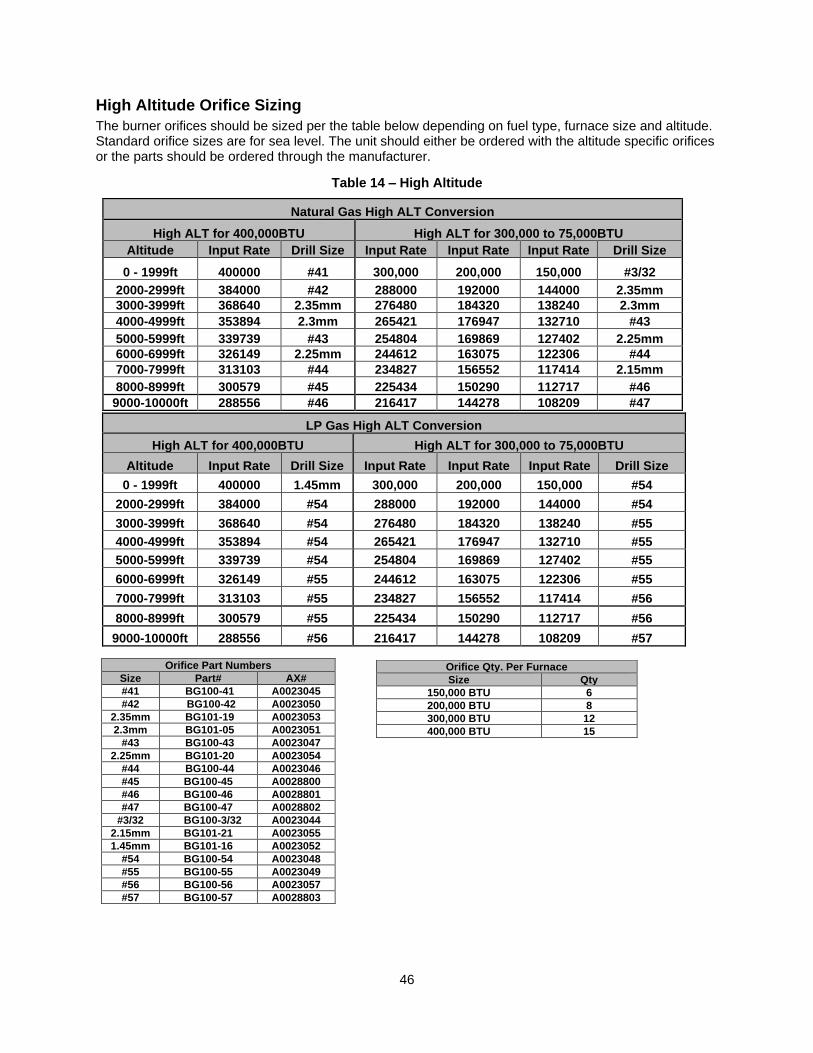
46
High Altitude Orifice Sizing
The burner orifices should be sized per the table below depending on fuel type, furnace size and altitude. Standard orifice sizes are for sea level. The unit should either be ordered with the altitude specific orifices or the parts should be ordered through the manufacturer.
Table 14 – High Altitude
Natural Gas High ALT Conversion
High ALT for 400,000BTU High ALT for 300,000 to 75,000BTU
Altitude Input Rate Drill Size Input Rate Input Rate Input Rate Drill Size
0 - 1999ft 400000 #41 300,000 200,000 150,000 #3/32
2000-2999ft 384000 #42 288000 192000 144000 2.35mm
3000-3999ft 368640 2.35mm 276480 184320 138240 2.3mm
4000-4999ft 353894 2.3mm 265421 176947 132710 #43
5000-5999ft 339739 #43 254804 169869 127402 2.25mm
6000-6999ft 326149 2.25mm 244612 163075 122306 #44
7000-7999ft 313103 #44 234827 156552 117414 2.15mm
8000-8999ft 300579 #45 225434 150290 112717 #46
9000-10000ft 288556 #46 216417 144278 108209 #47
LP Gas High ALT Conversion
High ALT for 400,000BTU High ALT for 300,000 to 75,000BTU
Altitude Input Rate Drill Size Input Rate Input Rate Input Rate Drill Size
0 - 1999ft 400000 1.45mm 300,000 200,000 150,000 #54
2000-2999ft 384000 #54 288000 192000 144000 #54
3000-3999ft 368640 #54 276480 184320 138240 #55
4000-4999ft 353894 #54 265421 176947 132710 #55
5000-5999ft 339739 #54 254804 169869 127402 #55
6000-6999ft 326149 #55 244612 163075 122306 #55
7000-7999ft 313103 #55 234827 156552 117414 #56
8000-8999ft 300579 #55 225434 150290 112717 #56
9000-10000ft 288556 #56 216417 144278 108209 #57
Orifice Part Numbers
Size Part# AX#
#41 BG100-41 A0023045
#42 BG100-42 A0023050
2.35mm BG101-19 A0023053
2.3mm BG101-05 A0023051
#43 BG100-43 A0023047
2.25mm BG101-20 A0023054
#44 BG100-44 A0023046
#45 BG100-45 A0028800
#46 BG100-46 A0028801
#47 BG100-47 A0028802
#3/32 BG100-3/32 A0023044
2.15mm BG101-21 A0023055
1.45mm BG101-16 A0023052
#54 BG100-54 A0023048
#55 BG100-55 A0023049
#56 BG100-56 A0023057
#57 BG100-57 A0028803
Orifice Qty. Per Furnace
Size Qty
150,000 BTU 6
200,000 BTU 8
300,000 BTU 12
400,000 BTU 15
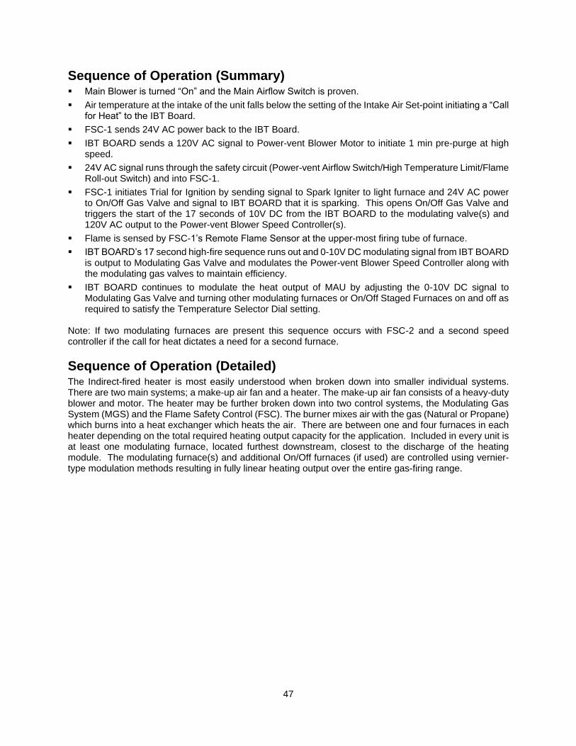
47
Sequence of Operation (Summary)
▪ Main Blower is turned “On” and the Main Airflow Switch is proven.
▪ Air temperature at the intake of the unit falls below the setting of the Intake Air Set-point initiating a “Call for Heat” to the IBT Board.
▪ FSC-1 sends 24V AC power back to the IBT Board.
▪ IBT BOARD sends a 120V AC signal to Power-vent Blower Motor to initiate 1 min pre-purge at high speed.
▪ 24V AC signal runs through the safety circuit (Power-vent Airflow Switch/High Temperature Limit/Flame Roll-out Switch) and into FSC-1.
▪ FSC-1 initiates Trial for Ignition by sending signal to Spark Igniter to light furnace and 24V AC power to On/Off Gas Valve and signal to IBT BOARD that it is sparking. This opens On/Off Gas Valve and triggers the start of the 17 seconds of 10V DC from the IBT BOARD to the modulating valve(s) and 120V AC output to the Power-vent Blower Speed Controller(s).
▪ Flame is sensed by FSC-1’s Remote Flame Sensor at the upper-most firing tube of furnace.
▪ IBT BOARD’s 17 second high-fire sequence runs out and 0-10V DC modulating signal from IBT BOARD is output to Modulating Gas Valve and modulates the Power-vent Blower Speed Controller along with the modulating gas valves to maintain efficiency.
▪ IBT BOARD continues to modulate the heat output of MAU by adjusting the 0-10V DC signal to Modulating Gas Valve and turning other modulating furnaces or On/Off Staged Furnaces on and off as required to satisfy the Temperature Selector Dial setting.
Note: If two modulating furnaces are present this sequence occurs with FSC-2 and a second speed controller if the call for heat dictates a need for a second furnace.
Sequence of Operation (Detailed) The Indirect-fired heater is most easily understood when broken down into smaller individual systems. There are two main systems; a make-up air fan and a heater. The make-up air fan consists of a heavy-duty blower and motor. The heater may be further broken down into two control systems, the Modulating Gas System (MGS) and the Flame Safety Control (FSC). The burner mixes air with the gas (Natural or Propane) which burns into a heat exchanger which heats the air. There are between one and four furnaces in each heater depending on the total required heating output capacity for the application. Included in every unit is at least one modulating furnace, located furthest downstream, closest to the discharge of the heating module. The modulating furnace(s) and additional On/Off furnaces (if used) are controlled using vernier-type modulation methods resulting in fully linear heating output over the entire gas-firing range.
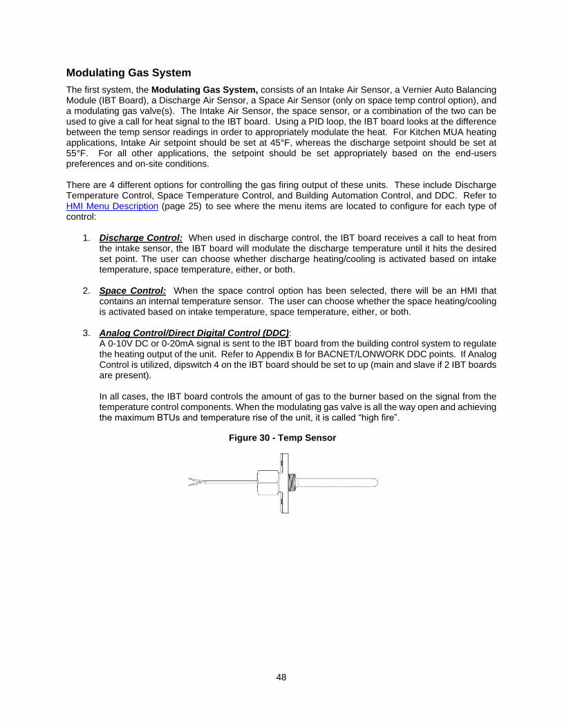
48
Modulating Gas System
The first system, the Modulating Gas System, consists of an Intake Air Sensor, a Vernier Auto Balancing Module (IBT Board), a Discharge Air Sensor, a Space Air Sensor (only on space temp control option), and a modulating gas valve(s). The Intake Air Sensor, the space sensor, or a combination of the two can be used to give a call for heat signal to the IBT board. Using a PID loop, the IBT board looks at the difference between the temp sensor readings in order to appropriately modulate the heat. For Kitchen MUA heating applications, Intake Air setpoint should be set at 45°F, whereas the discharge setpoint should be set at 55°F. For all other applications, the setpoint should be set appropriately based on the end-users preferences and on-site conditions. There are 4 different options for controlling the gas firing output of these units. These include Discharge Temperature Control, Space Temperature Control, and Building Automation Control, and DDC. Refer to HMI Menu Description (page 25) to see where the menu items are located to configure for each type of control:
1. Discharge Control: When used in discharge control, the IBT board receives a call to heat from the intake sensor, the IBT board will modulate the discharge temperature until it hits the desired set point. The user can choose whether discharge heating/cooling is activated based on intake temperature, space temperature, either, or both.
2. Space Control: When the space control option has been selected, there will be an HMI that contains an internal temperature sensor. The user can choose whether the space heating/cooling is activated based on intake temperature, space temperature, either, or both.
3. Analog Control/Direct Digital Control (DDC): A 0-10V DC or 0-20mA signal is sent to the IBT board from the building control system to regulate the heating output of the unit. Refer to Appendix B for BACNET/LONWORK DDC points. If Analog Control is utilized, dipswitch 4 on the IBT board should be set to up (main and slave if 2 IBT boards are present). In all cases, the IBT board controls the amount of gas to the burner based on the signal from the temperature control components. When the modulating gas valve is all the way open and achieving the maximum BTUs and temperature rise of the unit, it is called “high fire”.
Figure 30 - Temp Sensor
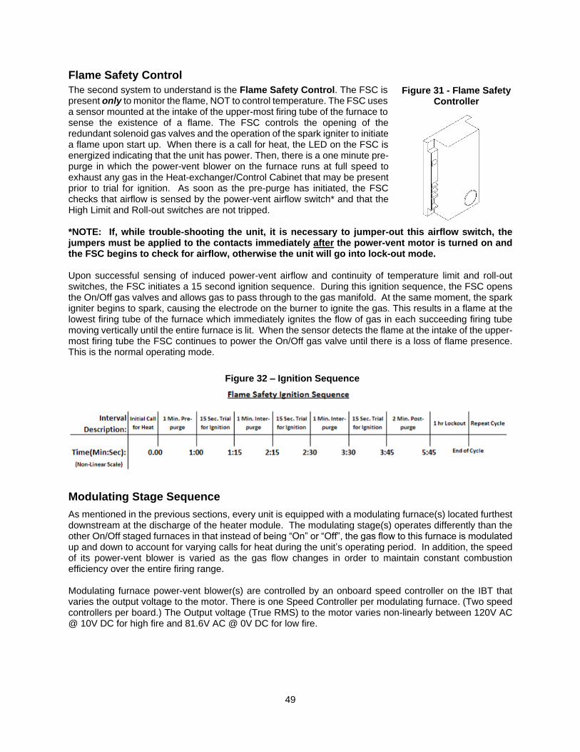
49
Flame Safety Control
The second system to understand is the Flame Safety Control. The FSC is present only to monitor the flame, NOT to control temperature. The FSC uses a sensor mounted at the intake of the upper-most firing tube of the furnace to sense the existence of a flame. The FSC controls the opening of the redundant solenoid gas valves and the operation of the spark igniter to initiate a flame upon start up. When there is a call for heat, the LED on the FSC is energized indicating that the unit has power. Then, there is a one minute pre-purge in which the power-vent blower on the furnace runs at full speed to exhaust any gas in the Heat-exchanger/Control Cabinet that may be present prior to trial for ignition. As soon as the pre-purge has initiated, the FSC checks that airflow is sensed by the power-vent airflow switch* and that the High Limit and Roll-out switches are not tripped. *NOTE: If, while trouble-shooting the unit, it is necessary to jumper-out this airflow switch, the jumpers must be applied to the contacts immediately after the power-vent motor is turned on and the FSC begins to check for airflow, otherwise the unit will go into lock-out mode. Upon successful sensing of induced power-vent airflow and continuity of temperature limit and roll-out switches, the FSC initiates a 15 second ignition sequence. During this ignition sequence, the FSC opens the On/Off gas valves and allows gas to pass through to the gas manifold. At the same moment, the spark igniter begins to spark, causing the electrode on the burner to ignite the gas. This results in a flame at the lowest firing tube of the furnace which immediately ignites the flow of gas in each succeeding firing tube moving vertically until the entire furnace is lit. When the sensor detects the flame at the intake of the upper-most firing tube the FSC continues to power the On/Off gas valve until there is a loss of flame presence. This is the normal operating mode.
Modulating Stage Sequence
As mentioned in the previous sections, every unit is equipped with a modulating furnace(s) located furthest downstream at the discharge of the heater module. The modulating stage(s) operates differently than the other On/Off staged furnaces in that instead of being “On” or “Off”, the gas flow to this furnace is modulated up and down to account for varying calls for heat during the unit’s operating period. In addition, the speed of its power-vent blower is varied as the gas flow changes in order to maintain constant combustion efficiency over the entire firing range. Modulating furnace power-vent blower(s) are controlled by an onboard speed controller on the IBT that varies the output voltage to the motor. There is one Speed Controller per modulating furnace. (Two speed controllers per board.) The Output voltage (True RMS) to the motor varies non-linearly between 120V AC @ 10V DC for high fire and 81.6V AC @ 0V DC for low fire.
Figure 31 - Flame Safety Controller
Figure 32 – Ignition Sequence
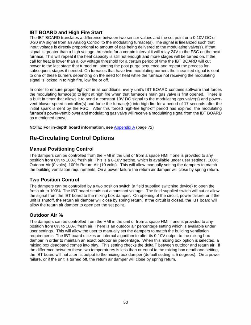
50
IBT BOARD and High Fire Start The IBT BOARD translates a difference between two sensor values and the set point or a 0-10V DC or 0-20 mA signal from an Analog Control to the modulating furnace(s). The signal is linearized such that input voltage is directly proportional to amount of gas being delivered to the modulating valve(s). If that signal is greater than a high voltage threshold for a certain interval it will relay 24V to the FSC on the next furnace. This will repeat if the heat capacity is still not enough and more stages will be turned on. If the call for heat is lower than a low voltage threshold for a certain period of time the IBT BOARD will cut power to the last stage that turned on, starting the post purge sequence and repeat the process for subsequent stages if needed. On furnaces that have two modulating burners the linearized signal is sent to one of these burners depending on the need for heat while the furnace not receiving the modulating signal is locked in to high fire, low fire or off. In order to ensure proper light-off in all conditions, every unit’s IBT BOARD contains software that forces the modulating furnace(s) to light at high fire when that furnace’s main gas valve is first opened. There is a built in timer that allows it to send a constant 10V DC signal to the modulating gas valve(s) and power-vent blower speed controller(s) and force the furnace(s) into high fire for a period of 17 seconds after the initial spark is sent by the FSC. After this forced high-fire light-off period has expired, the modulating furnace’s power-vent blower and modulating gas valve will receive a modulating signal from the IBT BOARD as mentioned above. NOTE: For in-depth board information, see Appendix A (page 72)
Re-Circulating Control Options
Manual Positioning Control
The dampers can be controlled from the HMI in the unit or from a space HMI if one is provided to any position from 0% to 100% fresh air. This is a 0-10V setting, which is available under user settings, 100% Outdoor Air (0 volts), 100% Return Air (10 volts). This will allow manually setting the dampers to match the building ventilation requirements. On a power failure the return air damper will close by spring return.
Two Position Control
The dampers can be controlled by a two position switch (a field supplied switching device) to open the fresh air to 100%. The IBT board sends out a constant voltage. The field supplied switch will cut or allow the signal from the IBT board to the mixing box damper. On opening of the circuit, power failure, or if the unit is shutoff, the return air damper will close by spring return. If the circuit is closed, the IBT board will allow the return air damper to open per the set point.
Outdoor Air %
The dampers can be controlled from the HMI in the unit or from a space HMI if one is provided to any position from 0% to 100% fresh air. There is an outdoor air percentage setting which is available under user settings. This will allow the user to manually set the dampers to match the building ventilation requirements. The IBT board utilizes an internal algorithm to alter its 0-10V output to the mixing box damper in order to maintain an exact outdoor air percentage. When this mixing box option is selected, a mixing box deadband comes into play. This setting checks the delta T between outdoor and return air. If the difference between these two temperatures is less than or equal to the mixing box deadband setting, the IBT board will not alter its output to the mixing box damper (default setting is 5 degrees). On a power failure, or if the unit is turned off, the return air damper will close by spring return.
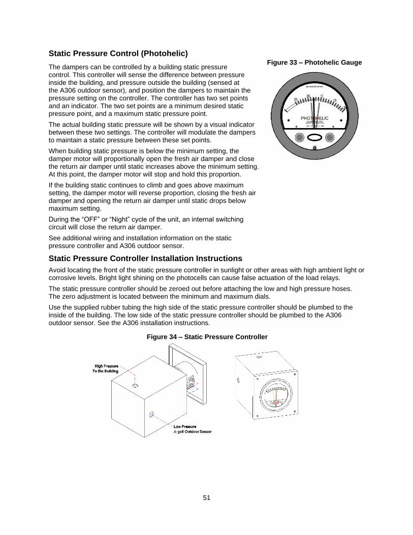
51
Static Pressure Control (Photohelic)
The dampers can be controlled by a building static pressure control. This controller will sense the difference between pressure inside the building, and pressure outside the building (sensed at the A306 outdoor sensor), and position the dampers to maintain the pressure setting on the controller. The controller has two set points and an indicator. The two set points are a minimum desired static pressure point, and a maximum static pressure point.
The actual building static pressure will be shown by a visual indicator between these two settings. The controller will modulate the dampers to maintain a static pressure between these set points.
When building static pressure is below the minimum setting, the damper motor will proportionally open the fresh air damper and close the return air damper until static increases above the minimum setting. At this point, the damper motor will stop and hold this proportion.
If the building static continues to climb and goes above maximum setting, the damper motor will reverse proportion, closing the fresh air damper and opening the return air damper until static drops below maximum setting.
During the “OFF” or “Night” cycle of the unit, an internal switching circuit will close the return air damper.
See additional wiring and installation information on the static pressure controller and A306 outdoor sensor.
Static Pressure Controller Installation Instructions
Avoid locating the front of the static pressure controller in sunlight or other areas with high ambient light or corrosive levels. Bright light shining on the photocells can cause false actuation of the load relays.
The static pressure controller should be zeroed out before attaching the low and high pressure hoses. The zero adjustment is located between the minimum and maximum dials.
Use the supplied rubber tubing the high side of the static pressure controller should be plumbed to the inside of the building. The low side of the static pressure controller should be plumbed to the A306 outdoor sensor. See the A306 installation instructions.
Figure 34 – Static Pressure Controller
Figure 33 – Photohelic Gauge
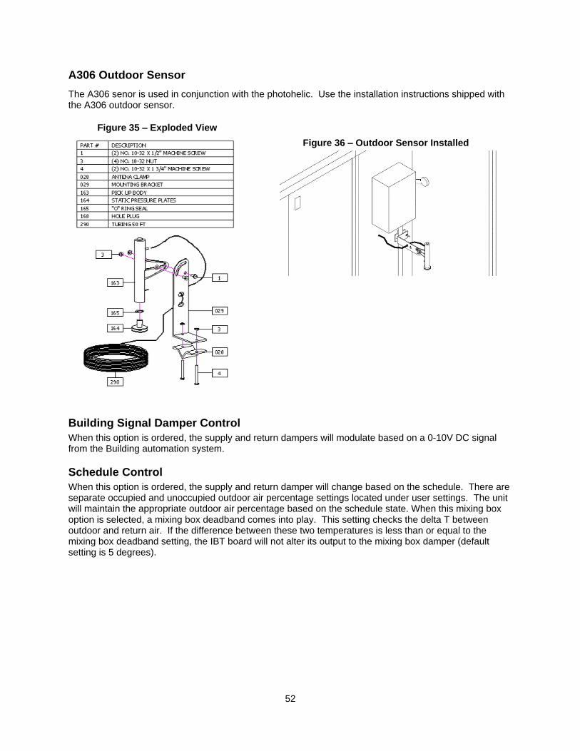
52
A306 Outdoor Sensor
The A306 senor is used in conjunction with the photohelic. Use the installation instructions shipped with the A306 outdoor sensor.
Building Signal Damper Control
When this option is ordered, the supply and return dampers will modulate based on a 0-10V DC signal from the Building automation system.
Schedule Control
When this option is ordered, the supply and return damper will change based on the schedule. There are separate occupied and unoccupied outdoor air percentage settings located under user settings. The unit will maintain the appropriate outdoor air percentage based on the schedule state. When this mixing box option is selected, a mixing box deadband comes into play. This setting checks the delta T between outdoor and return air. If the difference between these two temperatures is less than or equal to the mixing box deadband setting, the IBT board will not alter its output to the mixing box damper (default setting is 5 degrees).
Figure 36 – Outdoor Sensor Installed
Figure 35 – Exploded View
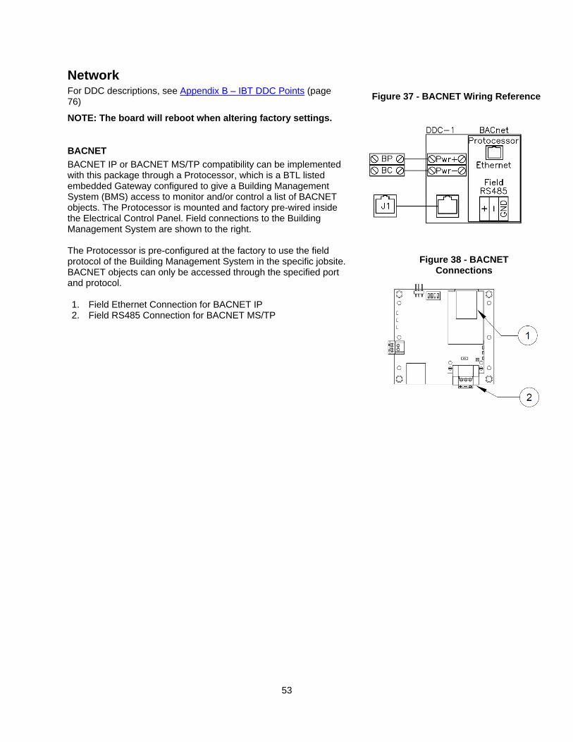
53
Network For DDC descriptions, see Appendix B – IBT DDC Points (page 76)
NOTE: The board will reboot when altering factory settings.
BACNET
BACNET IP or BACNET MS/TP compatibility can be implemented with this package through a Protocessor, which is a BTL listed embedded Gateway configured to give a Building Management System (BMS) access to monitor and/or control a list of BACNET objects. The Protocessor is mounted and factory pre-wired inside the Electrical Control Panel. Field connections to the Building Management System are shown to the right. The Protocessor is pre-configured at the factory to use the field protocol of the Building Management System in the specific jobsite. BACNET objects can only be accessed through the specified port and protocol. 1. Field Ethernet Connection for BACNET IP 2. Field RS485 Connection for BACNET MS/TP
Figure 38 - BACNET Connections
Figure 37 - BACNET Wiring Reference
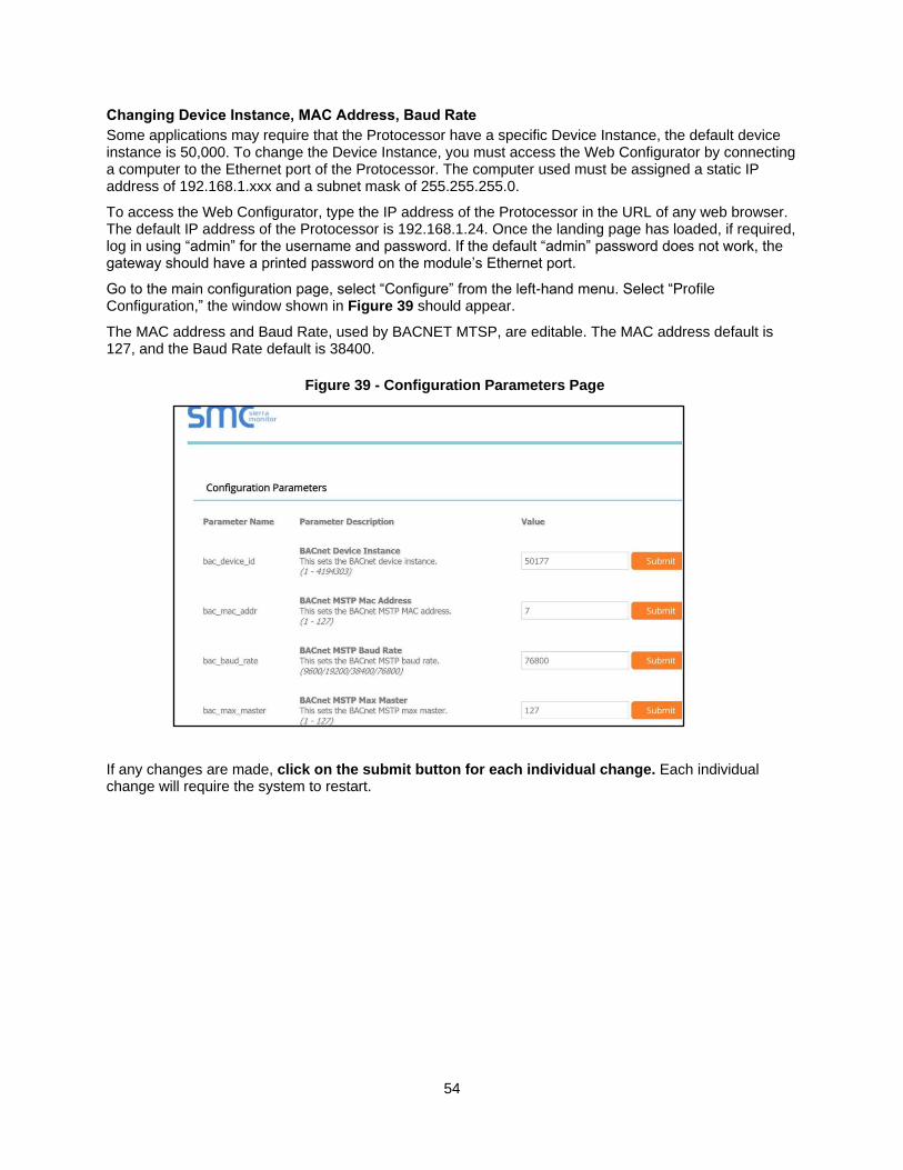
54
Changing Device Instance, MAC Address, Baud Rate
Some applications may require that the Protocessor have a specific Device Instance, the default device instance is 50,000. To change the Device Instance, you must access the Web Configurator by connecting a computer to the Ethernet port of the Protocessor. The computer used must be assigned a static IP address of 192.168.1.xxx and a subnet mask of 255.255.255.0.
To access the Web Configurator, type the IP address of the Protocessor in the URL of any web browser. The default IP address of the Protocessor is 192.168.1.24. Once the landing page has loaded, if required, log in using “admin” for the username and password. If the default “admin” password does not work, the gateway should have a printed password on the module’s Ethernet port.
Go to the main configuration page, select “Configure” from the left-hand menu. Select “Profile Configuration,” the window shown in Figure 39 should appear.
The MAC address and Baud Rate, used by BACNET MTSP, are editable. The MAC address default is 127, and the Baud Rate default is 38400.
If any changes are made, click on the submit button for each individual change. Each individual change will require the system to restart.
Figure 39 - Configuration Parameters Page
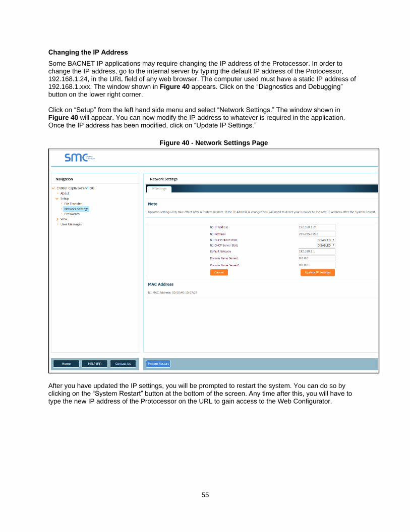
55
Changing the IP Address
Some BACNET IP applications may require changing the IP address of the Protocessor. In order to change the IP address, go to the internal server by typing the default IP address of the Protocessor, 192.168.1.24, in the URL field of any web browser. The computer used must have a static IP address of 192.168.1.xxx. The window shown in Figure 40 appears. Click on the “Diagnostics and Debugging” button on the lower right corner. Click on “Setup” from the left hand side menu and select “Network Settings.” The window shown in Figure 40 will appear. You can now modify the IP address to whatever is required in the application. Once the IP address has been modified, click on “Update IP Settings.”
After you have updated the IP settings, you will be prompted to restart the system. You can do so by clicking on the “System Restart” button at the bottom of the screen. Any time after this, you will have to type the new IP address of the Protocessor on the URL to gain access to the Web Configurator.
Figure 40 - Network Settings Page
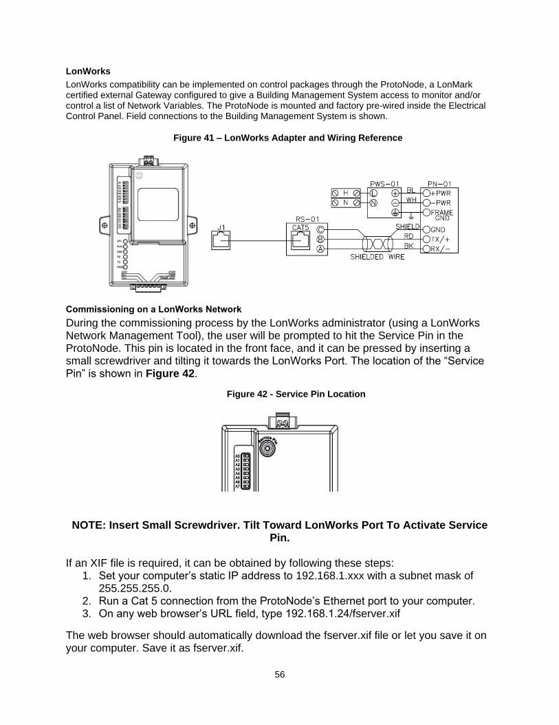
56
LonWorks
LonWorks compatibility can be implemented on control packages through the ProtoNode, a LonMark certified external Gateway configured to give a Building Management System access to monitor and/or control a list of Network Variables. The ProtoNode is mounted and factory pre-wired inside the Electrical Control Panel. Field connections to the Building Management System is shown.
Commissioning on a LonWorks Network
During the commissioning process by the LonWorks administrator (using a LonWorks Network Management Tool), the user will be prompted to hit the Service Pin in the ProtoNode. This pin is located in the front face, and it can be pressed by inserting a small screwdriver and tilting it towards the LonWorks Port. The location of the “Service Pin” is shown in Figure 42. NOTE: Insert Small Screwdriver. Tilt Toward LonWorks Port To Activate Service
Pin. If an XIF file is required, it can be obtained by following these steps:
1. Set your computer’s static IP address to 192.168.1.xxx with a subnet mask of 255.255.255.0.
2. Run a Cat 5 connection from the ProtoNode’s Ethernet port to your computer. 3. On any web browser’s URL field, type 192.168.1.24/fserver.xif
The web browser should automatically download the fserver.xif file or let you save it on your computer. Save it as fserver.xif.
Figure 41 – LonWorks Adapter and Wiring Reference
Figure 42 - Service Pin Location
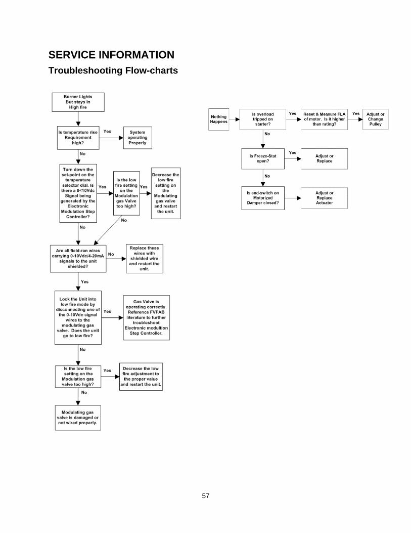
57
SERVICE INFORMATION
Troubleshooting Flow-charts
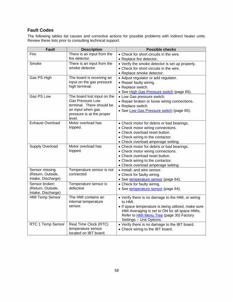
58
Fault Codes
The following tables list causes and corrective actions for possible problems with indirect heater units. Review these lists prior to consulting technical support.
Fault Description Possible checks
Fire There is an input from the fire detector.
• Check for short circuits in the wire.
• Replace fire detector.
Smoke There is an input from the smoke detector.
• Verify the smoke detector is set up properly.
• Check for short circuits in the wire.
• Replace smoke detector.
Gas PS High The board is receiving an input on the gas pressure high terminal.
• Adjust regulator or add regulator.
• Repair faulty wiring.
• Replace switch.
• See High Gas Pressure switch (page 65).
Gas PS Low The board lost input on the Gas Pressure Low terminal. There should be an input when gas pressure is at the proper level.
• Low Gas pressure switch.
• Repair broken or loose wiring connections.
• Replace switch.
• See Low Gas Pressure switch (page 65).
Exhaust Overload Motor overload has tripped.
• Check motor for debris or bad bearings. • Check motor wiring connections.
• Check overload reset button.
• Check wiring to the contactor.
• Check overload amperage setting.
Supply Overload Motor overload has tripped.
• Check motor for debris or bad bearings. • Check motor wiring connections.
• Check overload reset button.
• Check wiring to the contactor.
• Check overload amperage setting.
Sensor missing (Return, Outside, Intake, Discharge)
Temperature sensor is not connected
• Install, and wire sensor.
• Check for faulty wiring.
• See temperature sensor (page 64).
Sensor broken (Return, Outside, Intake, Discharge)
Temperature sensor is defective
• Check for faulty wiring.
• See temperature sensor (page 64).
HMI Temp Sensor The HMI contains an internal temperature sensor.
• Verify there is no damage to the HMI, or wiring to HMI.
• If space temperature is being utilized, make sure HMI Averaging is set to ON for all space HMIs. Refer to HMI Menu Tree (page 30) Factory Settings – Unit Options.
RTC 1 Temp Sensor Real Time Clock (RTC) temperature sensor located on IBT board.
• Verify there is no damage to the IBT board.
• Check wiring to the IBT board.
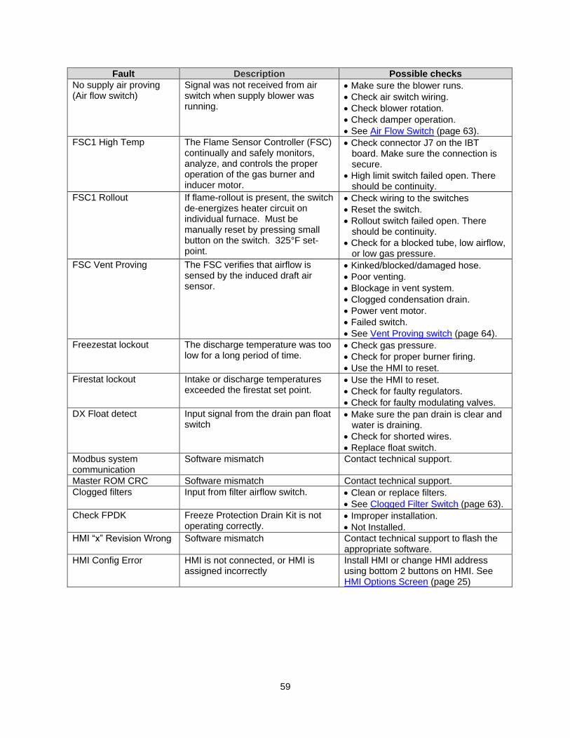
59
Fault Description Possible checks
No supply air proving (Air flow switch)
Signal was not received from air switch when supply blower was running.
• Make sure the blower runs.
• Check air switch wiring.
• Check blower rotation.
• Check damper operation.
• See Air Flow Switch (page 63).
FSC1 High Temp The Flame Sensor Controller (FSC) continually and safely monitors, analyze, and controls the proper operation of the gas burner and inducer motor.
• Check connector J7 on the IBT board. Make sure the connection is secure.
• High limit switch failed open. There should be continuity.
FSC1 Rollout If flame-rollout is present, the switch de-energizes heater circuit on individual furnace. Must be manually reset by pressing small button on the switch. 325°F set-point.
• Check wiring to the switches
• Reset the switch.
• Rollout switch failed open. There should be continuity.
• Check for a blocked tube, low airflow, or low gas pressure.
FSC Vent Proving
The FSC verifies that airflow is sensed by the induced draft air sensor.
• Kinked/blocked/damaged hose.
• Poor venting.
• Blockage in vent system.
• Clogged condensation drain.
• Power vent motor.
• Failed switch.
• See Vent Proving switch (page 64).
Freezestat lockout The discharge temperature was too low for a long period of time.
• Check gas pressure.
• Check for proper burner firing.
• Use the HMI to reset.
Firestat lockout Intake or discharge temperatures exceeded the firestat set point.
• Use the HMI to reset.
• Check for faulty regulators.
• Check for faulty modulating valves.
DX Float detect Input signal from the drain pan float switch
• Make sure the pan drain is clear and water is draining.
• Check for shorted wires.
• Replace float switch.
Modbus system communication
Software mismatch Contact technical support.
Master ROM CRC Software mismatch Contact technical support.
Clogged filters Input from filter airflow switch. • Clean or replace filters.
• See Clogged Filter Switch (page 63).
Check FPDK Freeze Protection Drain Kit is not operating correctly.
• Improper installation.
• Not Installed.
HMI “x” Revision Wrong Software mismatch Contact technical support to flash the appropriate software.
HMI Config Error
HMI is not connected, or HMI is assigned incorrectly
Install HMI or change HMI address using bottom 2 buttons on HMI. See HMI Options Screen (page 25)
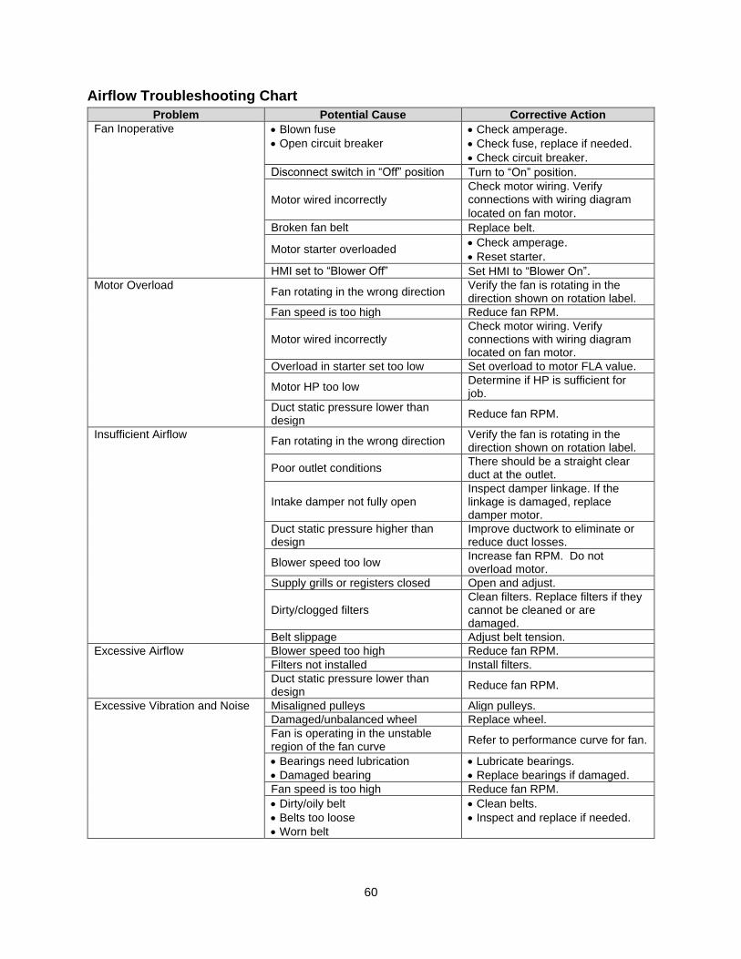
60
Airflow Troubleshooting Chart
Problem Potential Cause Corrective Action
Fan Inoperative • Blown fuse
• Open circuit breaker
• Check amperage. • Check fuse, replace if needed. • Check circuit breaker.
Disconnect switch in “Off” position Turn to “On” position.
Motor wired incorrectly
Check motor wiring. Verify connections with wiring diagram
located on fan motor.
Broken fan belt Replace belt.
Motor starter overloaded • Check amperage. • Reset starter.
HMI set to “Blower Off” Set HMI to “Blower On”. Motor Overload
Fan rotating in the wrong direction Verify the fan is rotating in the direction shown on rotation label.
Fan speed is too high Reduce fan RPM.
Motor wired incorrectly Check motor wiring. Verify connections with wiring diagram located on fan motor.
Overload in starter set too low Set overload to motor FLA value.
Motor HP too low Determine if HP is sufficient for job.
Duct static pressure lower than design
Reduce fan RPM.
Insufficient Airflow Fan rotating in the wrong direction
Verify the fan is rotating in the direction shown on rotation label.
Poor outlet conditions There should be a straight clear duct at the outlet.
Intake damper not fully open Inspect damper linkage. If the linkage is damaged, replace damper motor.
Duct static pressure higher than design
Improve ductwork to eliminate or reduce duct losses.
Blower speed too low Increase fan RPM. Do not overload motor.
Supply grills or registers closed Open and adjust.
Dirty/clogged filters Clean filters. Replace filters if they cannot be cleaned or are damaged.
Belt slippage Adjust belt tension.
Excessive Airflow Blower speed too high Reduce fan RPM.
Filters not installed Install filters.
Duct static pressure lower than design
Reduce fan RPM.
Excessive Vibration and Noise Misaligned pulleys Align pulleys.
Damaged/unbalanced wheel Replace wheel.
Fan is operating in the unstable region of the fan curve
Refer to performance curve for fan.
• Bearings need lubrication
• Damaged bearing
• Lubricate bearings.
• Replace bearings if damaged.
Fan speed is too high Reduce fan RPM.
• Dirty/oily belt
• Belts too loose
• Worn belt
• Clean belts.
• Inspect and replace if needed.
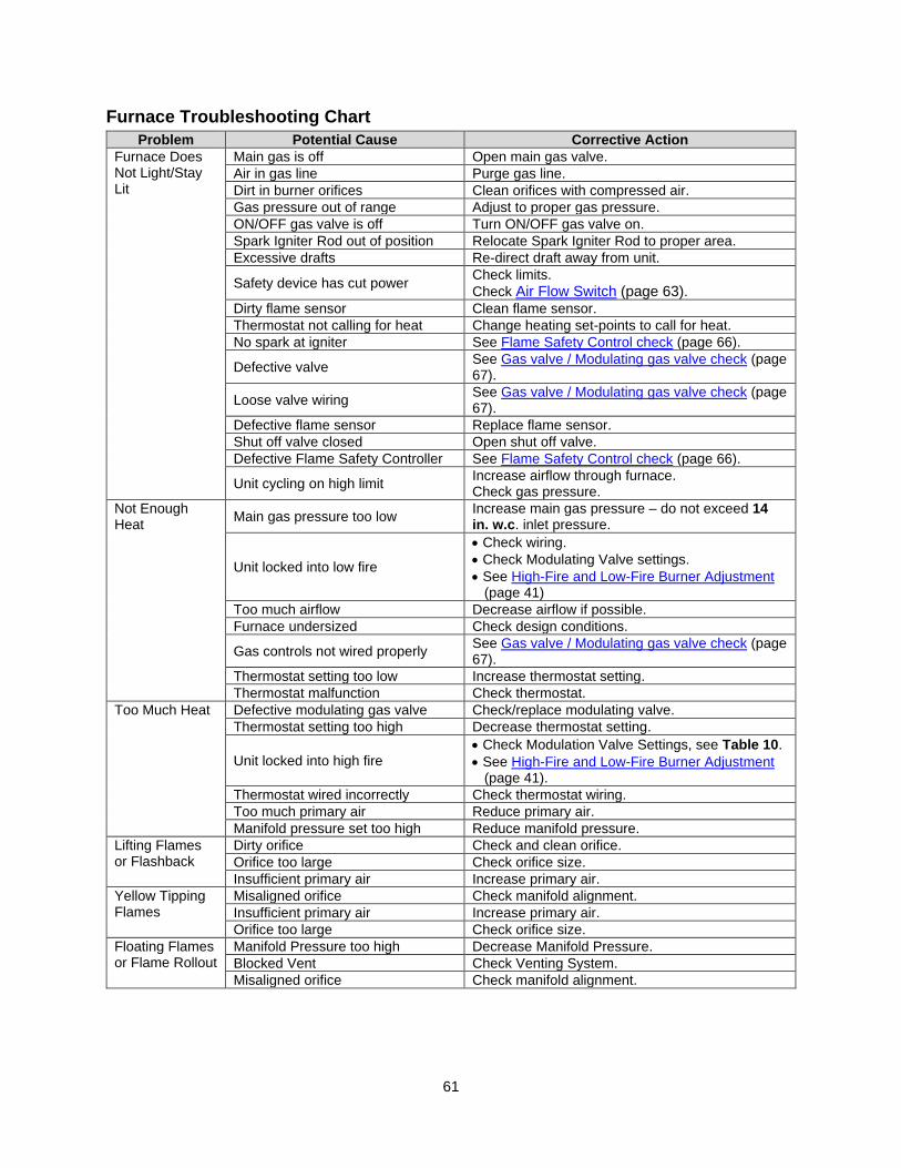
61
Furnace Troubleshooting Chart
Problem Potential Cause Corrective Action
Furnace Does Not Light/Stay Lit
Main gas is off Open main gas valve.
Air in gas line Purge gas line.
Dirt in burner orifices Clean orifices with compressed air.
Gas pressure out of range Adjust to proper gas pressure.
ON/OFF gas valve is off Turn ON/OFF gas valve on.
Spark Igniter Rod out of position Relocate Spark Igniter Rod to proper area.
Excessive drafts Re-direct draft away from unit.
Safety device has cut power Check limits.
Check Air Flow Switch (page 63). Dirty flame sensor Clean flame sensor.
Thermostat not calling for heat Change heating set-points to call for heat.
No spark at igniter See Flame Safety Control check (page 66).
Defective valve See Gas valve / Modulating gas valve check (page 67).
Loose valve wiring See Gas valve / Modulating gas valve check (page 67).
Defective flame sensor Replace flame sensor.
Shut off valve closed Open shut off valve.
Defective Flame Safety Controller See Flame Safety Control check (page 66).
Unit cycling on high limit Increase airflow through furnace. Check gas pressure.
Not Enough Heat
Main gas pressure too low Increase main gas pressure – do not exceed 14 in. w.c. inlet pressure.
Unit locked into low fire
• Check wiring.
• Check Modulating Valve settings.
• See High-Fire and Low-Fire Burner Adjustment (page 41)
Too much airflow Decrease airflow if possible.
Furnace undersized Check design conditions.
Gas controls not wired properly See Gas valve / Modulating gas valve check (page 67).
Thermostat setting too low Increase thermostat setting.
Thermostat malfunction Check thermostat.
Too Much Heat Defective modulating gas valve Check/replace modulating valve.
Thermostat setting too high Decrease thermostat setting.
Unit locked into high fire • Check Modulation Valve Settings, see Table 10. • See High-Fire and Low-Fire Burner Adjustment
(page 41).
Thermostat wired incorrectly Check thermostat wiring.
Too much primary air Reduce primary air.
Manifold pressure set too high Reduce manifold pressure.
Lifting Flames or Flashback
Dirty orifice Check and clean orifice.
Orifice too large Check orifice size.
Insufficient primary air Increase primary air.
Yellow Tipping Flames
Misaligned orifice Check manifold alignment.
Insufficient primary air Increase primary air.
Orifice too large Check orifice size.
Floating Flames or Flame Rollout
Manifold Pressure too high Decrease Manifold Pressure.
Blocked Vent Check Venting System.
Misaligned orifice Check manifold alignment.
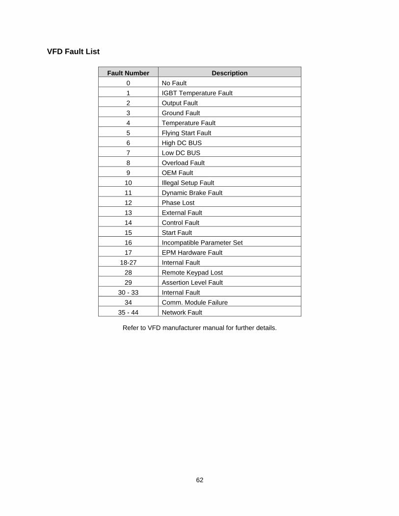
62
VFD Fault List
Fault Number Description
0 No Fault
1 IGBT Temperature Fault
2 Output Fault
3 Ground Fault
4 Temperature Fault
5 Flying Start Fault
6 High DC BUS
7 Low DC BUS
8 Overload Fault
9 OEM Fault
10 Illegal Setup Fault
11 Dynamic Brake Fault
12 Phase Lost
13 External Fault
14 Control Fault
15 Start Fault
16 Incompatible Parameter Set
17 EPM Hardware Fault
18-27 Internal Fault
28 Remote Keypad Lost
29 Assertion Level Fault
30 - 33 Internal Fault
34 Comm. Module Failure
35 - 44 Network Fault
Refer to VFD manufacturer manual for further details.
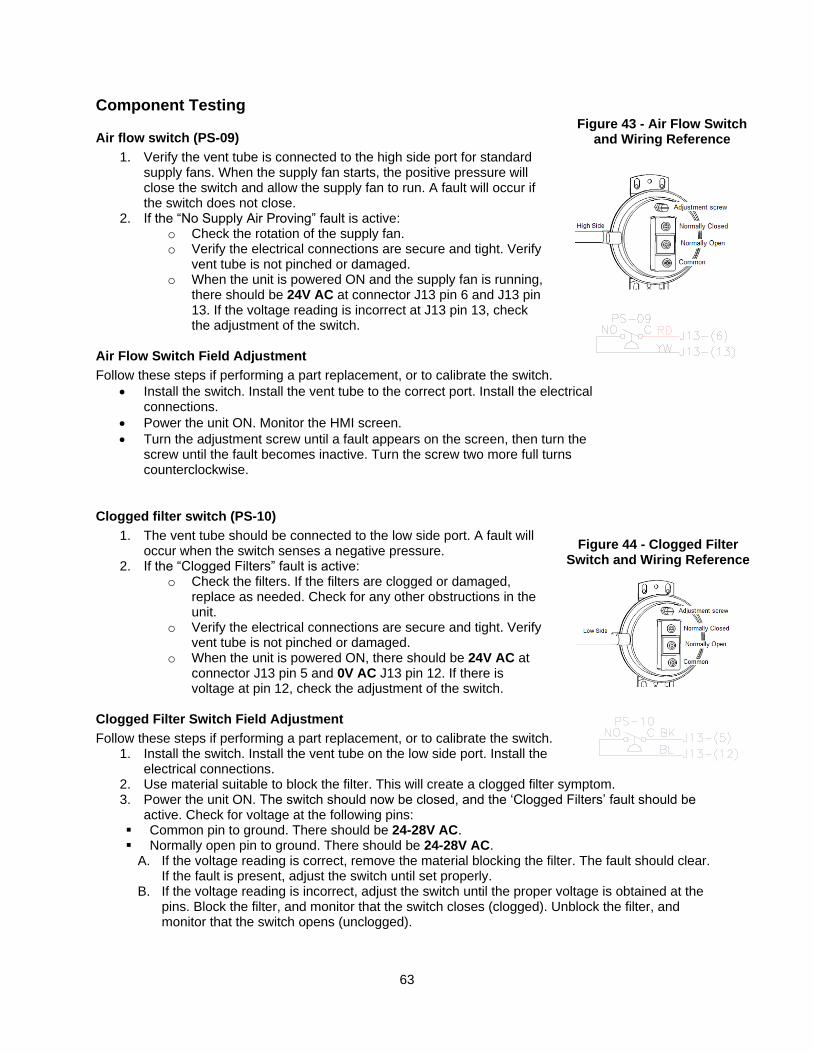
63
Component Testing
Air flow switch (PS-09)
1. Verify the vent tube is connected to the high side port for standard supply fans. When the supply fan starts, the positive pressure will close the switch and allow the supply fan to run. A fault will occur if the switch does not close.
2. If the “No Supply Air Proving” fault is active: o Check the rotation of the supply fan. o Verify the electrical connections are secure and tight. Verify
vent tube is not pinched or damaged. o When the unit is powered ON and the supply fan is running,
there should be 24V AC at connector J13 pin 6 and J13 pin 13. If the voltage reading is incorrect at J13 pin 13, check the adjustment of the switch.
Air Flow Switch Field Adjustment
Follow these steps if performing a part replacement, or to calibrate the switch.
• Install the switch. Install the vent tube to the correct port. Install the electrical connections.
• Power the unit ON. Monitor the HMI screen.
• Turn the adjustment screw until a fault appears on the screen, then turn the screw until the fault becomes inactive. Turn the screw two more full turns counterclockwise.
Clogged filter switch (PS-10)
1. The vent tube should be connected to the low side port. A fault will occur when the switch senses a negative pressure.
2. If the “Clogged Filters” fault is active: o Check the filters. If the filters are clogged or damaged,
replace as needed. Check for any other obstructions in the unit.
o Verify the electrical connections are secure and tight. Verify vent tube is not pinched or damaged.
o When the unit is powered ON, there should be 24V AC at connector J13 pin 5 and 0V AC J13 pin 12. If there is voltage at pin 12, check the adjustment of the switch.
Clogged Filter Switch Field Adjustment
Follow these steps if performing a part replacement, or to calibrate the switch. 1. Install the switch. Install the vent tube on the low side port. Install the electrical connections. 2. Use material suitable to block the filter. This will create a clogged filter symptom. 3. Power the unit ON. The switch should now be closed, and the ‘Clogged Filters’ fault should be active. Check for voltage at the following pins: ▪ Common pin to ground. There should be 24-28V AC. ▪ Normally open pin to ground. There should be 24-28V AC.
A. If the voltage reading is correct, remove the material blocking the filter. The fault should clear. If the fault is present, adjust the switch until set properly.
B. If the voltage reading is incorrect, adjust the switch until the proper voltage is obtained at the pins. Block the filter, and monitor that the switch closes (clogged). Unblock the filter, and monitor that the switch opens (unclogged).
Figure 44 - Clogged Filter Switch and Wiring Reference
Figure 43 - Air Flow Switch and Wiring Reference
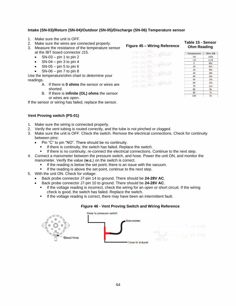
64
Intake (SN-03)/Return (SN-04)/Outdoor (SN-05)/Discharge (SN-06) Temperature sensor 1. Make sure the unit is OFF. 2. Make sure the wires are connected properly. 3. Measure the resistance of the temperature sensor
at the IBT board connector J15.
• SN-03 – pin 1 to pin 2
• SN-04 – pin 3 to pin 4
• SN-05 – pin 5 to pin 6
• SN-06 – pin 7 to pin 8 Use the temperature/ohm chart to determine your readings.
A. If there is 0 ohms the sensor or wires are shorted.
B. If there is infinite (OL) ohms the sensor or wires are open.
If the sensor or wiring has failed, replace the sensor. Vent Proving switch (PS-01) 1. Make sure the wiring is connected properly. 2. Verify the vent tubing is routed correctly, and the tube is not pinched or clogged. 3. Make sure the unit is OFF. Check the switch. Remove the electrical connections. Check for continuity
between pins:
• Pin “C” to pin “NO”. There should be no continuity. ▪ If there is continuity, the switch has failed. Replace the switch. ▪ If there is no continuity, re-connect the electrical connections. Continue to the next step.
4. Connect a manometer between the pressure switch, and hose. Power the unit ON, and monitor the manometer. Verify the value (w.c.) on the switch is correct.
▪ If the reading is below the set point, there is an issue with the vacuum. ▪ If the reading is above the set point, continue to the next step.
5. With the unit ON. Check for voltage:
• Back probe connector J7-pin 14 to ground. There should be 24-28V AC.
• Back probe connector J7-pin 10 to ground. There should be 24-28V AC. ▪ If the voltage reading is incorrect, check the wiring for an open or short circuit. If the wiring
check is good, the switch has failed. Replace the switch. ▪ If the voltage reading is correct, there may have been an intermittent fault.
Table 15 - Sensor Ohm Reading Figure 45 – Wiring Reference
Figure 46 - Vent Proving Switch and Wiring Reference
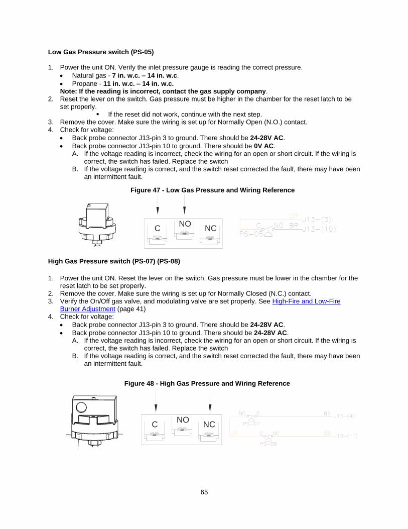
65
Low Gas Pressure switch (PS-05)
1. Power the unit ON. Verify the inlet pressure gauge is reading the correct pressure.
• Natural gas - 7 in. w.c. – 14 in. w.c.
• Propane - 11 in. w.c. – 14 in. w.c. Note: If the reading is incorrect, contact the gas supply company.
2. Reset the lever on the switch. Gas pressure must be higher in the chamber for the reset latch to be set properly.
▪ If the reset did not work, continue with the next step. 3. Remove the cover. Make sure the wiring is set up for Normally Open (N.O.) contact. 4. Check for voltage:
• Back probe connector J13-pin 3 to ground. There should be 24-28V AC.
• Back probe connector J13-pin 10 to ground. There should be 0V AC. A. If the voltage reading is incorrect, check the wiring for an open or short circuit. If the wiring is
correct, the switch has failed. Replace the switch B. If the voltage reading is correct, and the switch reset corrected the fault, there may have been
an intermittent fault. High Gas Pressure switch (PS-07) (PS-08)
1. Power the unit ON. Reset the lever on the switch. Gas pressure must be lower in the chamber for the
reset latch to be set properly. 2. Remove the cover. Make sure the wiring is set up for Normally Closed (N.C.) contact. 3. Verify the On/Off gas valve, and modulating valve are set properly. See High-Fire and Low-Fire
Burner Adjustment (page 41) 4. Check for voltage:
• Back probe connector J13-pin 3 to ground. There should be 24-28V AC.
• Back probe connector J13-pin 10 to ground. There should be 24-28V AC. A. If the voltage reading is incorrect, check the wiring for an open or short circuit. If the wiring is
correct, the switch has failed. Replace the switch B. If the voltage reading is correct, and the switch reset corrected the fault, there may have been
an intermittent fault.
Figure 47 - Low Gas Pressure and Wiring Reference
Figure 48 - High Gas Pressure and Wiring Reference
CNO
NC
CNO
NC
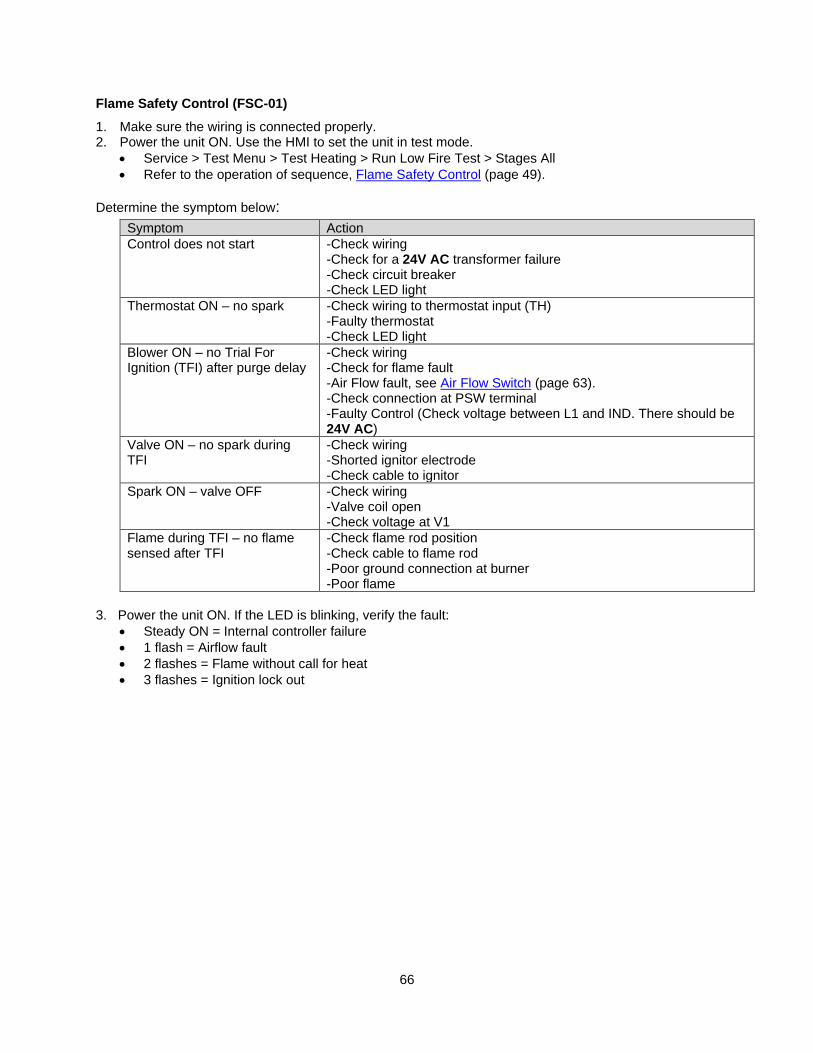
66
Flame Safety Control (FSC-01)
1. Make sure the wiring is connected properly. 2. Power the unit ON. Use the HMI to set the unit in test mode.
• Service > Test Menu > Test Heating > Run Low Fire Test > Stages All
• Refer to the operation of sequence, Flame Safety Control (page 49).
Determine the symptom below:
Symptom Action
Control does not start -Check wiring -Check for a 24V AC transformer failure -Check circuit breaker -Check LED light
Thermostat ON – no spark -Check wiring to thermostat input (TH) -Faulty thermostat -Check LED light
Blower ON – no Trial For Ignition (TFI) after purge delay
-Check wiring -Check for flame fault -Air Flow fault, see Air Flow Switch (page 63). -Check connection at PSW terminal -Faulty Control (Check voltage between L1 and IND. There should be 24V AC)
Valve ON – no spark during TFI
-Check wiring -Shorted ignitor electrode -Check cable to ignitor
Spark ON – valve OFF -Check wiring -Valve coil open -Check voltage at V1
Flame during TFI – no flame sensed after TFI
-Check flame rod position -Check cable to flame rod -Poor ground connection at burner -Poor flame
3. Power the unit ON. If the LED is blinking, verify the fault:
• Steady ON = Internal controller failure
• 1 flash = Airflow fault
• 2 flashes = Flame without call for heat
• 3 flashes = Ignition lock out
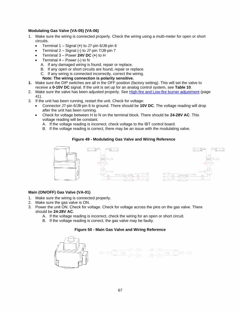
67
Modulating Gas Valve (VA-05) (VA-06)
1. Make sure the wiring is connected properly. Check the wiring using a multi-meter for open or short circuits. • Terminal 1 – Signal (+) to J7-pin 6/J8-pin 6
• Terminal 2 – Signal (-) to J7-pin 7/J8-pin 7
• Terminal 3 – Power 24V DC (+) to H
• Terminal 4 – Power (-) to N A. If any damaged wiring is found, repair or replace. B. If any open or short circuits are found, repair or replace. C. If any wiring is connected incorrectly, correct the wiring.
Note: The wiring connection is polarity sensitive. 1. Make sure the DIP switches are all in the OFF position (factory setting). This will set the valve to
receive a 0-10V DC signal. If the unit is set up for an analog control system, see Table 10. 2. Make sure the valve has been adjusted properly. See High-fire and Low-fire burner adjustment (page
41). 3. If the unit has been running, restart the unit. Check for voltage:
• Connector J7-pin 6/J8-pin 6 to ground. There should be 10V DC. The voltage reading will drop after the unit has been running.
• Check for voltage between H to N on the terminal block. There should be 24-28V AC. This voltage reading will be constant. A. If the voltage reading is incorrect, check voltage to the IBT control board. B. If the voltage reading is correct, there may be an issue with the modulating valve.
Main (ON/OFF) Gas Valve (VA-01)
1. Make sure the wiring is connected properly. 2. Make sure the gas valve is ON. 3. Power the unit ON. Check for voltage. Check for voltage across the pins on the gas valve. There
should be 24-28V AC. A. If the voltage reading is incorrect, check the wiring for an open or short circuit. B. If the voltage reading is correct, the gas valve may be faulty.
Figure 50 - Main Gas Valve and Wiring Reference
Figure 49 - Modulating Gas Valve and Wiring Reference
68
MAINTENANCE
To guarantee trouble free operation of this heater, the manufacturer suggests following these guidelines. Most problems associated with fan failures are directly related to poor service and maintenance. Please record any maintenance or service performed on this fan in the documentation section located at the end of this manual.
WARNING: DO NOT ATTEMPT MAINTENANCE ON THE HEATER UNTIL THE ELECTRICAL SUPPLY HAS BEEN COMPLETELY DISCONNECTED AND THE MAIN GAS SUPPLY VALVE HAS BEEN TURNED OFF.
General Maintenance 1. Fan inlet and approaches to ventilator should be kept clean and free from any obstruction.
2. Motors are normally permanently lubricated. Check bearings periodically. If they have grease fittings lubricate each season. Use caution when lubricating bearings, wipe the fittings clean, the unit should be rotated by hand while lubricating. Caution: Use care when touching the exterior of an operating motor. Motors normally run hot and may be hot enough to be painful or cause injury.
3. All fasteners should be checked for tightness each time maintenance checks are preformed prior to restarting unit.
4. Blowers require very little attention when moving clean air. Occasionally oil and dust may accumulate causing imbalance. If the fan is installed in a corrosive or dirty atmosphere, periodically inspect and clean the wheel, inlet and other moving parts to ensure smooth and safe operation.
5. Before each heating season, verify that the drain on the bottom of each common flue box of every furnace in the unit is clear.
Re-Setting of the Unit If the flame safety control is locked out (Spark igniter fails or no gas supply), reset the unit by:
1. Turn OFF Power to the unit. 2. Turn Power to the unit back ON.
Emergency shutdown of unit To shut down the unit in the event of an emergency do the following:
1. Turn power OFF to the unit from main building disconnect. 2. Turn the external disconnect switch to the OFF position. 3. CLOSE the inlet gas valve located on the heater.
Prolonged shutdown of the unit For prolonged shutdown the following steps should be done:
1. Turn the external disconnect switch to the OFF position. 2. CLOSE the inlet gas valve located on the heater.
To re-start the unit the following steps should be done:
1. Turn the external disconnect switch to the ON position. 2. OPEN the inlet gas valve located on the heater.
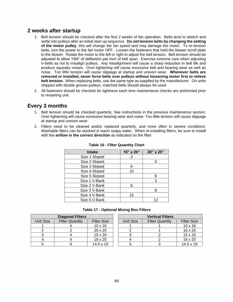
69
2 weeks after startup 1. Belt tension should be checked after the first 2 weeks of fan operation. Belts tend to stretch and
settle into pulleys after an initial start-up sequence. Do not tension belts by changing the setting of the motor pulley, this will change the fan speed and may damage the motor. To re-tension belts, turn the power to the fan motor OFF. Loosen the fasteners that hold the blower scroll plate to the blower. Rotate the motor to the left or right to adjust the belt tension. Belt tension should be adjusted to allow 1/64” of deflection per inch of belt span. Exercise extreme care when adjusting V-belts as not to misalign pulleys. Any misalignment will cause a sharp reduction in belt life and produce squeaky noises. Over-tightening will cause excessive belt and bearing wear as well as noise. Too little tension will cause slippage at startup and uneven wear. Whenever belts are removed or installed, never force belts over pulleys without loosening motor first to relieve belt tension. When replacing belts, use the same type as supplied by the manufacturer. On units shipped with double groove pulleys, matched belts should always be used.
2. All fasteners should be checked for tightness each time maintenance checks are preformed prior to restarting unit.
Every 3 months 1. Belt tension should be checked quarterly. See instructions in the previous maintenance section.
Over-tightening will cause excessive bearing wear and noise. Too little tension will cause slippage at startup and uneven wear.
2. Filters need to be cleaned and/or replaced quarterly, and more often in severe conditions. Washable filters can be washed in warm soapy water. When re-installing filters, be sure to install with the airflow in the correct direction as indicated on the filter.
Table 16 - Filter Quantity Chart
Intake 16” x 20” 20” x 25”
Size 1 Sloped 3
Size 2 Sloped 3
Size 3 Sloped 6
Size 4 Sloped 10
Size 5 Sloped 8
Size 1 V-Bank 3
Size 2 V-Bank 8
Size 3 V-Bank 8
Size 4 V-Bank 15
Size 5 V-Bank 12
Table 17 - Optional Mixing Box Filters
Diagonal Filters Vertical Filters
Unit Size Filter Quantity Filter Size Unit Size Filter Quantity Filter Size
1 4 10 x 16 1 1 10 x 16
2 2 20 x 25 2 1 16 x 25
3 4 15 x 20 3 2 15 x 15
4 4 18 x 25 4 2 16 x 20
5 9 14.5 x 19 5 3 14.5 x 19
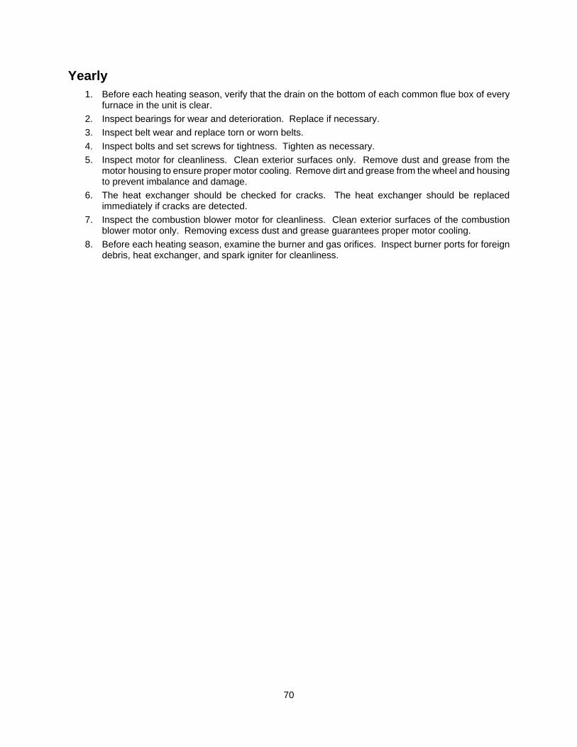
70
Yearly
1. Before each heating season, verify that the drain on the bottom of each common flue box of every furnace in the unit is clear.
2. Inspect bearings for wear and deterioration. Replace if necessary.
3. Inspect belt wear and replace torn or worn belts.
4. Inspect bolts and set screws for tightness. Tighten as necessary.
5. Inspect motor for cleanliness. Clean exterior surfaces only. Remove dust and grease from the motor housing to ensure proper motor cooling. Remove dirt and grease from the wheel and housing to prevent imbalance and damage.
6. The heat exchanger should be checked for cracks. The heat exchanger should be replaced immediately if cracks are detected.
7. Inspect the combustion blower motor for cleanliness. Clean exterior surfaces of the combustion blower motor only. Removing excess dust and grease guarantees proper motor cooling.
8. Before each heating season, examine the burner and gas orifices. Inspect burner ports for foreign debris, heat exchanger, and spark igniter for cleanliness.
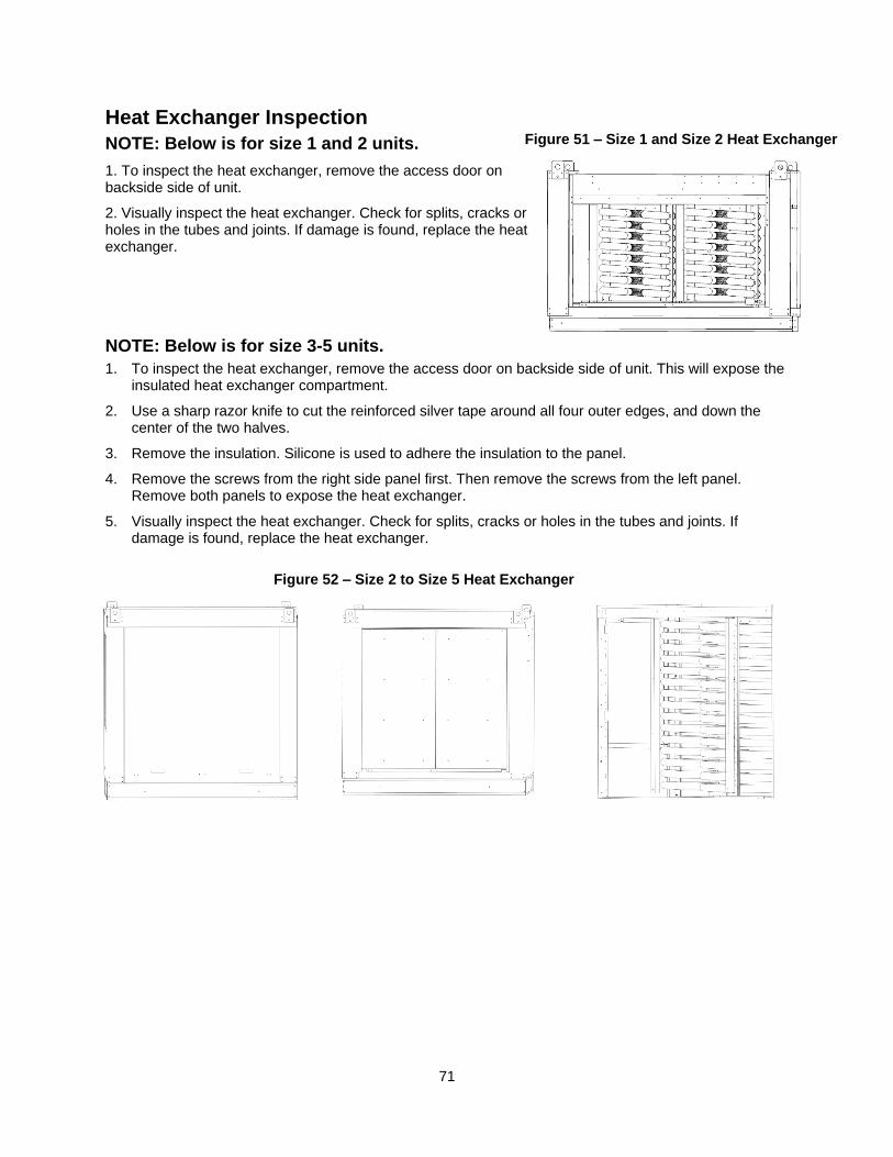
71
Heat Exchanger Inspection
NOTE: Below is for size 1 and 2 units.
1. To inspect the heat exchanger, remove the access door on backside side of unit.
2. Visually inspect the heat exchanger. Check for splits, cracks or holes in the tubes and joints. If damage is found, replace the heat exchanger.
NOTE: Below is for size 3-5 units.
1. To inspect the heat exchanger, remove the access door on backside side of unit. This will expose the insulated heat exchanger compartment.
2. Use a sharp razor knife to cut the reinforced silver tape around all four outer edges, and down the center of the two halves.
3. Remove the insulation. Silicone is used to adhere the insulation to the panel.
4. Remove the screws from the right side panel first. Then remove the screws from the left panel. Remove both panels to expose the heat exchanger.
5. Visually inspect the heat exchanger. Check for splits, cracks or holes in the tubes and joints. If damage is found, replace the heat exchanger.
Figure 51 – Size 1 and Size 2 Heat Exchanger
Figure 52 – Size 2 to Size 5 Heat Exchanger
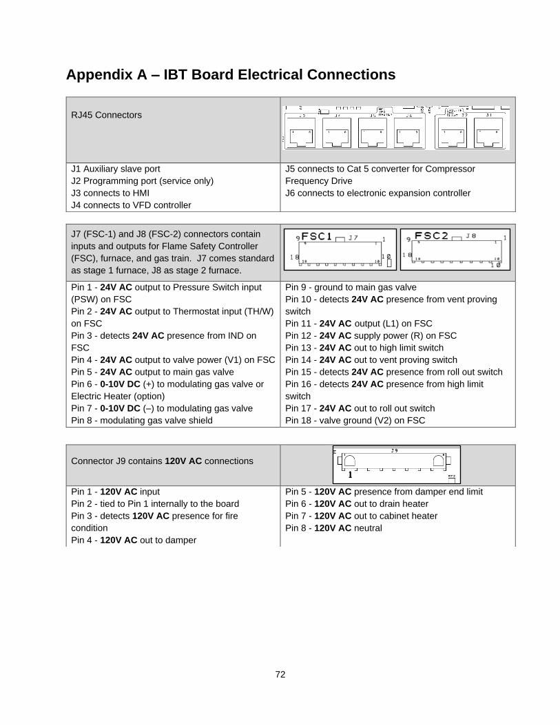
72
Appendix A – IBT Board Electrical Connections
RJ45 Connectors
J1 Auxiliary slave port
J2 Programming port (service only)
J3 connects to HMI
J4 connects to VFD controller
J5 connects to Cat 5 converter for Compressor
Frequency Drive
J6 connects to electronic expansion controller
J7 (FSC-1) and J8 (FSC-2) connectors contain
inputs and outputs for Flame Safety Controller
(FSC), furnace, and gas train. J7 comes standard
as stage 1 furnace, J8 as stage 2 furnace.
Pin 1 - 24V AC output to Pressure Switch input
(PSW) on FSC
Pin 2 - 24V AC output to Thermostat input (TH/W)
on FSC
Pin 3 - detects 24V AC presence from IND on
FSC
Pin 4 - 24V AC output to valve power (V1) on FSC
Pin 5 - 24V AC output to main gas valve
Pin 6 - 0-10V DC (+) to modulating gas valve or
Electric Heater (option)
Pin 7 - 0-10V DC (–) to modulating gas valve
Pin 8 - modulating gas valve shield
Pin 9 - ground to main gas valve
Pin 10 - detects 24V AC presence from vent proving
switch
Pin 11 - 24V AC output (L1) on FSC
Pin 12 - 24V AC supply power (R) on FSC
Pin 13 - 24V AC out to high limit switch
Pin 14 - 24V AC out to vent proving switch
Pin 15 - detects 24V AC presence from roll out switch
Pin 16 - detects 24V AC presence from high limit
switch
Pin 17 - 24V AC out to roll out switch
Pin 18 - valve ground (V2) on FSC
Connector J9 contains 120V AC connections
Pin 1 - 120V AC input
Pin 2 - tied to Pin 1 internally to the board
Pin 3 - detects 120V AC presence for fire
condition
Pin 4 - 120V AC out to damper
Pin 5 - 120V AC presence from damper end limit
Pin 6 - 120V AC out to drain heater
Pin 7 - 120V AC out to cabinet heater
Pin 8 - 120V AC neutral
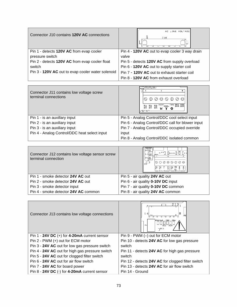
73
Connector J10 contains 120V AC connections
Pin 1 - detects 120V AC from evap cooler
pressure switch
Pin 2 - detects 120V AC from evap cooler float
switch
Pin 3 - 120V AC out to evap cooler water solenoid
Pin 4 - 120V AC out to evap cooler 3 way drain
valve
Pin 5 - detects 120V AC from supply overload
Pin 6 - 120V AC out to supply starter coil
Pin 7 - 120V AC out to exhaust starter coil Pin 8 - 120V AC from exhaust overload
Connector J11 contains low voltage screw terminal connections
Pin 1 - is an auxillary input
Pin 2 - is an auxiliary input
Pin 3 - is an auxiliary input
Pin 4 - Analog Control/DDC heat select input
Pin 5 - Analog Control/DDC cool select input
Pin 6 - Analog Control/DDC call for blower input
Pin 7 - Analog Control/DDC occupied override
input
Pin 8 - Analog Control/DDC isolated common
Connector J12 contains low voltage sensor screw terminal connection
Pin 1 - smoke detector 24V AC out
Pin 2 - smoke detector 24V AC out
Pin 3 - smoke detector input
Pin 4 - smoke detector 24V AC common
Pin 5 - air quality 24V AC out
Pin 6 - air quality 0-10V DC input
Pin 7 - air quality 0-10V DC common
Pin 8 - air quality 24V AC common
Connector J13 contains low voltage connections
Pin 1 - 24V DC (+) for 4-20mA current sensor
Pin 2 - PWM (+) out for ECM motor
Pin 3 - 24V AC out for low gas pressure switch
Pin 4 - 24V AC out for high gas pressure switch
Pin 5 - 24V AC out for clogged filter switch
Pin 6 - 24V AC out for air flow switch
Pin 7 - 24V AC for board power
Pin 8 - 24V DC (-) for 4-20mA current sensor
Pin 9 - PWM (–) out for ECM motor
Pin 10 - detects 24V AC for low gas pressure
switch
Pin 11 - detects 24V AC for high gas pressure
switch
Pin 12 - detects 24V AC for clogged filter switch
Pin 13 - detects 24V AC for air flow switch
Pin 14 - Ground
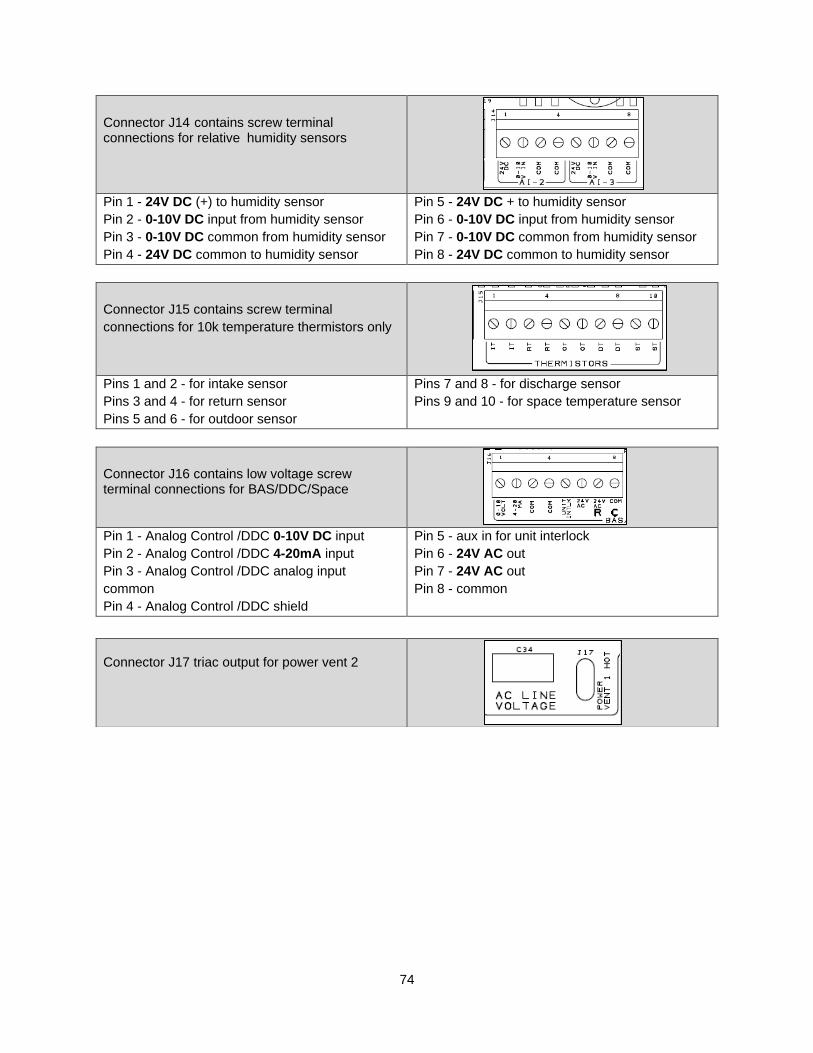
74
Connector J14 contains screw terminal connections for relative humidity sensors
Pin 1 - 24V DC (+) to humidity sensor
Pin 2 - 0-10V DC input from humidity sensor
Pin 3 - 0-10V DC common from humidity sensor
Pin 4 - 24V DC common to humidity sensor
Pin 5 - 24V DC + to humidity sensor
Pin 6 - 0-10V DC input from humidity sensor
Pin 7 - 0-10V DC common from humidity sensor
Pin 8 - 24V DC common to humidity sensor
Connector J15 contains screw terminal
connections for 10k temperature thermistors only
Pins 1 and 2 - for intake sensor
Pins 3 and 4 - for return sensor
Pins 5 and 6 - for outdoor sensor
Pins 7 and 8 - for discharge sensor
Pins 9 and 10 - for space temperature sensor
Connector J16 contains low voltage screw terminal connections for BAS/DDC/Space
Pin 1 - Analog Control /DDC 0-10V DC input
Pin 2 - Analog Control /DDC 4-20mA input
Pin 3 - Analog Control /DDC analog input
common
Pin 4 - Analog Control /DDC shield
Pin 5 - aux in for unit interlock
Pin 6 - 24V AC out
Pin 7 - 24V AC out
Pin 8 - common
Connector J17 triac output for power vent 2
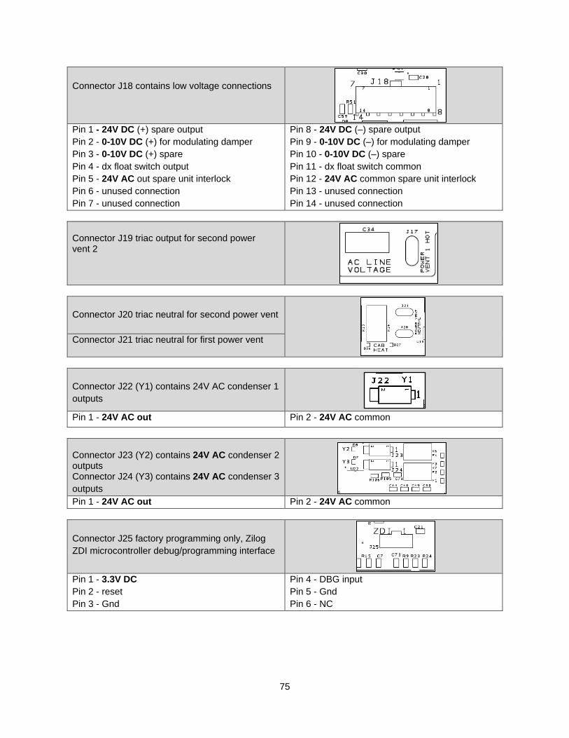
75
Connector J18 contains low voltage connections
Pin 1 - 24V DC (+) spare output
Pin 2 - 0-10V DC (+) for modulating damper
Pin 3 - 0-10V DC (+) spare
Pin 4 - dx float switch output
Pin 5 - 24V AC out spare unit interlock
Pin 6 - unused connection
Pin 7 - unused connection
Pin 8 - 24V DC (–) spare output
Pin 9 - 0-10V DC (–) for modulating damper
Pin 10 - 0-10V DC (–) spare
Pin 11 - dx float switch common
Pin 12 - 24V AC common spare unit interlock
Pin 13 - unused connection
Pin 14 - unused connection
Connector J19 triac output for second power vent 2
Connector J20 triac neutral for second power vent
Connector J21 triac neutral for first power vent
Connector J22 (Y1) contains 24V AC condenser 1
outputs
Pin 1 - 24V AC out Pin 2 - 24V AC common
Connector J23 (Y2) contains 24V AC condenser 2 outputs Connector J24 (Y3) contains 24V AC condenser 3
outputs
Pin 1 - 24V AC out Pin 2 - 24V AC common
Connector J25 factory programming only, Zilog
ZDI microcontroller debug/programming interface
Pin 1 - 3.3V DC
Pin 2 - reset
Pin 3 - Gnd
Pin 4 - DBG input
Pin 5 - Gnd
Pin 6 - NC

76
Appendix B – IBT DDC Points Full External Control Points:
BACNET OBJECT NAME
BACNET OBJECT
ID
BACNET DATA TYPE
LON SNVT NAME SNVT TYPE FUNCTION DEFAULT RANGE DESCRIPTION
HeatCommand 1 Binary Value
nviHeatCommand SNVT_count Control 0 0-1 OFF(0) / ON(1)
CoolCommand 2 Binary Value
nviCoolCommand SNVT_count Control 0 0-1 OFF(0) / ON(1)
FanCommand 3 Binary Value
nviFanCommand SNVT_count Control 0 0-1 OFF(0) / ON(1)
• Use only if Heating and/or Cooling tempering mode has been set to “DDC” through the unit’s HMI.
• Setting the Heating and Cooling modes to “DDC” disables temperature based activation of these
functions. The preferred heating and cooling activation method is to use space and/or intake
temperatures along with unit set points.
• Heating and Cooling cannot be called for at the same time.
• The Fan Control point will only work if the heating or cooling mode is set to DDC.
For factory settings and temperature set points BACNET and LON points are displayed on to the BMS as raw values. The BMS must scale these points when reading and/or writing based on the point description. For example, temperature sensor values must be divided by 10 after they are read. Likewise, when writing to a set point, the intended value must be multiplied by 10 before being sent to the controller.
Factory Settings: BACNET OBJECT NAME
BACNET OBJECT ID
BACNET DATA TYPE
LON SNVT NAME SNVT TYPE
FUNCTION DEFAULT RANGE DESCRIPTION
NumberofHMIs 4 Analog Value nviNumberofHMIs SNVT_ count
Monitor/Control 1 1-5 HMI1 is always the cabinet HMI
IncludeHMIAvg 5 Analog Value nviIncludeHMIAvg SNVT_ count
Monitor/Control 2 1-31 odd Bitfield, if bit=1 that HMI is read
only
SetHeatStages 6 Analog Value nviSetHeatStages SNVT_ count
Monitor/Control 0 0-4 One IBT Board can support 2
stages
SetCondenserStages 7 Analog Value nviSetCondStages SNVT_ count
Monitor/Control 0 0-5 Distinction between the number
of condensers and the number of condenser cooling stages
FreezestatTime 8 Analog Value nviFstatTime SNVT_ count
Monitor/Control 10 1-10 Time in Minutes
EvapSprayONTime 9 Analog Value nviEvSprayONt SNVT_ count
Monitor/Control Set By Plant
0-60 Time in Seconds
EvapSprayOFFTime 10 Analog Value nviEvSprayOFFt SNVT_ count
Monitor/Control Set By Plant
0-500 Time in Seconds
MinVFDFreqOccupied 11 Analog Value nviMinVFDFreqO SNVT_ count
Monitor/Control 0 0-MaxVFDFreq Freq(Hz)*10
MaxVFDFreqOccupied 12 Analog Value nviMaxVFDFreqO SNVT_ count
Monitor/Control 80 MinVFDFreq-
800 Freq(Hz)*10
MinOAPercentOccupied 13 Analog Value nviMinOAPercentO SNVT_ count
Monitor/Control 0 0-Max Outdoor
Air % Minimum Percentage of Outdoor
Air
MaxOAPercentOccupied 14 Analog Value nviMaxOAPercentO SNVT_ count
Monitor/Control 100 Min Outdoor Air
%-100 Maximum Percentage of Outdoor
Air
MinPWMOccupied 15 Analog Value nviMinPWMO SNVT_ count
Monitor/Control 0 0-Max PWM ECM Minimum Speed
MaxPWMOccupied 16 Analog Value nviMaxPWMO SNVT_ count
Monitor/Control 100 Min PWM-100 ECM Maximum Speed
SchedulingEnable 17 Binary Value nviSchedEnable SNVT_ count
Monitor/Control 0 0-1 Disabled (0) / Enabled (1)
CoolDXLowTempLimit 18 Analog Value nviCoolDLowTLim SNVT_ count
Monitor/Control 550°F 130°C
400-700°F 40-210°C
Temperature*10
EvapDrainValveSP 19 Analog Value
nviEvapDValveSP SNVT_ count
Monitor/Control 400°F 40°C
350-1100°F 20-100°C
Temperature*10
EvapDrainValveSPDiff 20 Analog Value
nviEvapDVlvSPDif SNVT_ count
Monitor/Control 20°F 20°C
10-50°F 10-30°C
Temperature*10
EvapCoolingDiff 21 Analog Value
nviEvapCoolDif SNVT_ count
Monitor/Control 30°F 20°C
10-100°F 10-60°C
Temperature*10
MinOAPercentUnoccupied 22 Analog Value nviMinOAPercentU SNVT_ count
Monitor/Control 0% 0-Max % Percentage of outdoor air
MaxOAPercentUnoccupied 23 Analog Value nviMaxOAPercentU SNVT_ count
Monitor/Control 100% Min-100% Percentage of outdoor air
MinVFDFreqUnoccupied 24 Analog Value nviMinVFDFreqU SNVT_ count
Monitor/Control 30Hz 0-VFD Max Freq (Hz) *10
MaxVFDFreqUnoccupied 25 Analog Value nviMaxVFDFreqU SNVT_ count
Monitor/Control 60Hz VFD Min-800 Freq (Hz) *10
MinPWMUnoccupied 26 Analog Value nviMinPWMU SNVT_ count
Monitor/Control 0% 0-Max PWM Motor speed %
MaxPWMUnoccupied 27 Analog Value nviMaxPWMU SNVT_ count
Monitor/Control 100% Min PWM - 100 Motor speed %
CoolEvapLowTempLimit 28 Analog Value nviCoolELowTLim SNVT_ count
Monitor/Control 800°F 38°C
60-100°F 16-38°C
Temperature*10
• Writing to any of these registers will trigger a system reboot. Avoid writing to these on a regular basis.
• The Scheduling Enable point tells the unit whether scheduling is allowed or not. It is NOT an occupancy command.
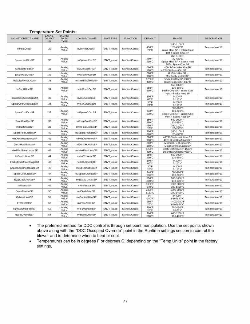
77
Temperature Set Points:
BACNET OBJECT NAME BACNET OBJECT
ID
BACNET DATA TYPE
LON SNVT NAME SNVT TYPE FUNCTION DEFAULT RANGE DESCRIPTION
InHeatOccSP 29 Analog Value
nviInHeatOccSP SNVT_count Monitor/Control 450°F 70°C
350-1100°F 20-430°C
Intake Heat SP + Intake Heat Diff < Intake Cool SP
Temperature*10
SpaceHeatOccSP 30 Analog Value
nviSpaceHOccSP SNVT_count Monitor/Control 700°F 210°C
350-1100°F 20-430°C
Space Heat SP + Space Heat Diff < Space Cool SP
Temperature*10
MinDischHeatSP 31 Analog Value
nviMinDischHSP SNVT_count Monitor/Control 600°F 160°C
400°F-DischHeatOccSP 40°C-DischHeatOccSP
Temperature*10
DischHeatOccSP 32 Analog Value
nviDischHOccSP SNVT_count Monitor/Control 600°F 160°C
MinDischHeatSP-MaxDischHeatOccSP
Temperature*10
MaxDischHeatOccSP 33 Analog Value
nviMaxDischHOcSP SNVT_count Monitor/Control 1200°F 490°C
DischHeatOccSP-1500°F DischHeatOccSP-660°C
Temperature*10
InCool1OccSP 34 Analog Value
nviInCool1OccSP SNVT_count Monitor/Control 850°F 290°C
550-1000°F 130-380°C
Intake Cool SP - Intake Cool Hyst > Intake Heat SP
Temperature*10
IntakeCoolOccStageDiff 35 Analog Value
nviInCOccStgDif SNVT_count Monitor/Control 100°F 60°C
0-200°F 0-110°C
Temperature*10
SpaceCoolOccStageDiff 36 Analog Value
nviSpCOccStgDif SNVT_count Monitor/Control 30°F 20°C
0-200°F 0-110°C
Temperature*10
SpaceCoolOccSP 37 Analog Value
nviSpaceCOccSP SNVT_count Monitor/Control 740°F 230°C
500-900°F 100-320°C
Space Cool SP - Space Cool Hyst > Space Heat SP
Temperature*10
EvapCoolOccSP 38 Analog Value
nviEvapCoolOccSP SNVT_count Monitor/Control 850°F 290°C
550-1000°F 130-380°C
Temperature*10
InHeatUnoccSP 39 Analog Value
nviInHeatUnoccSP SNVT_count Monitor/Control 450°F 70°C
350-1100°F 20-430°C
Temperature*10
SpaceHeatUnoccSP 40 Analog Value
nviSpaceHUnoccSP SNVT_count Monitor/Control 700°F 210°C
350-1100°F 20-430°C
Temperature*10
MinDischHeatUnoccSP 41 Analog Value
nviMinDisHUnocSP SNVT_count Monitor/Control 600°F 160°C
400°F-DischHeatUnoccSP 40°C-DischHeatUnoccSP
Temperature*10
DischHeatUnoccSP 42 Analog Value
nviDischHUnoccSP SNVT_count Monitor/Control 600°F 160°C
MinDischHeatUnoccSP-MaxDischHeatUnoccSP
Temperature*10
MaxDischHeatUnoccSP 43 Analog Value
nviMaxDisHUnocSP SNVT_count Monitor/Control 1200°F 490°C
DischHeatUnoccSP-1500°F DischHeatUnoccSP-660°C
Temperature*10
InCool1UnoccSP 44 Analog Value
nviInC1UnoccSP SNVT_count Monitor/Control 850°F 290°C
550-1000°F 130-380°C
Temperature*10
IntakeCoolUnoccStageDiff 45 Analog Value
nviInCUnocStgDif SNVT_count Monitor/Control 100°F 60°C
0-200°F 0-110°C
Temperature*10
SpaceCoolUnoccStageDiff 46 Analog Value
nviSpCUnocStgDif SNVT_count Monitor/Control 30°F 20°C
0-200°F 0-110°C
Temperature*10
SpaceCoolUnoccSP 47 Analog Value
nviSpaceCUnoccSP SNVT_count Monitor/Control 740°F 230°C
500-900°F 100-320°C
Temperature*10
EvapCoolUnoccSP 48 Analog Value
nviEvapCUnoccSP SNVT_count Monitor/Control 850°F 290°C
550-1000°F 130-380°C
Temperature*10
InFirestatSP 49 Analog Value
nviInFirestatSP SNVT_count Monitor/Control 1350°F 570°C
1000-3000°F 380-1490°C
Temperature*10
DischFirestatSP 50 Analog Value
nviDischFstatSP SNVT_count Monitor/Control 2400°F 1160°C
1000-3000°F 380-1490°C
Temperature*10
CabinetHeatSP 51 Analog Value
nviCabinetHeatSP SNVT_count Monitor/Control 0°F
-180°C 0-400°F
(-180)-40°C Temperature*10
FreezestatSP 52 Analog Value
nviFreezestatSP SNVT_count Monitor/Control 350°F 20°C
(-400)-750°F (-400)-24°C
Temperature*10
FurnaceDrainHeatSP 53 Analog Value
nviFurnDrainHSP SNVT_count Monitor/Control 350°F 20°C
350-450°F 20-70°C
Temperature*10
RoomOverrideSP 54 Analog Value
nviRoomOrideSP SNVT_count Monitor/Control 900°F 310°C
600-1200°F 160-490°C
Temperature*10
• The preferred method for DDC control is through set point manipulation. Use the set points shown
above along with the “DDC Occupied Override” point in the Runtime settings section to control the
blower and to determine when to heat or cool.
• Temperatures can be in degrees F or degrees C, depending on the “Temp Units” point in the factory
settings.
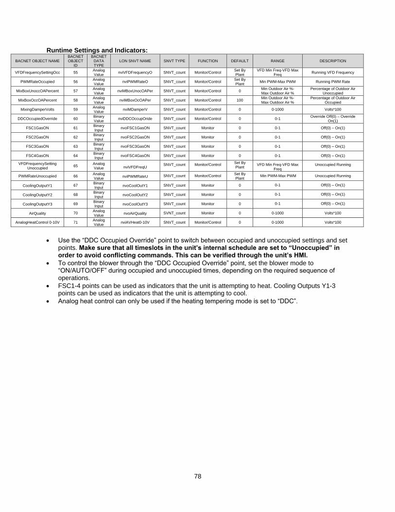
78
Runtime Settings and Indicators:
BACNET OBJECT NAME BACNET OBJECT
ID
BACNET DATA TYPE
LON SNVT NAME SNVT TYPE FUNCTION DEFAULT RANGE DESCRIPTION
VFDFrequencySettingOcc 55 Analog Value
nviVFDFrequencyO SNVT_count Monitor/Control Set By Plant
VFD Min Freq-VFD Max Freq
Running VFD Frequency
PWMRateOccupied 56 Analog Value
nviPWMRateO SNVT_count Monitor/Control Set By Plant
Min PWM-Max PWM Running PWM Rate
MixBoxUnoccOAPercent 57 Analog Value
nviMBoxUnocOAPer SNVT_count Monitor/Control 0 Min Outdoor Air %- Max Outdoor Air %
Percentage of Outdoor Air Unoccupied
MixBoxOccOAPercent 58 Analog Value
nviMBoxOcOAPer SNVT_count Monitor/Control 100 Min Outdoor Air %- Max Outdoor Air %
Percentage of Outdoor Air Occupied
MixingDamperVolts 59 Analog Value
nviMDamperV SNVT_count Monitor/Control 0 0-1000 Volts*100
DDCOccupiedOverride 60 Binary Value
nviDDCOccupOride SNVT_count Monitor/Control 0 0-1 Override Off(0) – Override
On(1)
FSC1GasON 61 Binary Input
nvoFSC1GasON SNVT_count Monitor 0 0-1 Off(0) – On(1)
FSC2GasON 62 Binary Input
nvoFSC2GasON SNVT_count Monitor 0 0-1 Off(0) – On(1)
FSC3GasON 63 Binary Input
nvoFSC3GasON SNVT_count Monitor 0 0-1 Off(0) – On(1)
FSC4GasON 64 Binary Input
nvoFSC4GasON SNVT_count Monitor 0 0-1 Off(0) – On(1)
VFDFrequencySetting Unoccupied
65 Analog Value nviVFDFreqU
SNVT_count Monitor/Control Set By Plant VFD Min Freq-VFD Max
Freq Unoccupied Running
PWMRateUnoccupied 66 Analog Value
nviPWMRateU SNVT_count Monitor/Control Set By Plant Min PWM-Max PWM Unoccupied Running
CoolingOutputY1 67 Binary Input
nvoCoolOutY1 SNVT_count Monitor 0 0-1 Off(0) – On(1)
CoolingOutputY2 68 Binary Input
nvoCoolOutY2 SNVT_count Monitor 0 0-1 Off(0) – On(1)
CoolingOutputY3 69 Binary Input
nvoCoolOutY3 SNVT_count Monitor 0 0-1 Off(0) – On(1)
AirQuality 70 Analog Value
nvoAirQuality SVNT_count Monitor 0 0-1000 Volts*100
AnalogHeatControl 0-10V 71 Analog Value
nviAVHeat0-10V SNVT_count Monitor/Control 0 0-1000 Volts*100
• Use the “DDC Occupied Override” point to switch between occupied and unoccupied settings and set
points. Make sure that all timeslots in the unit’s internal schedule are set to “Unoccupied” in order to avoid conflicting commands. This can be verified through the unit’s HMI.
• To control the blower through the “DDC Occupied Override” point, set the blower mode to “ON/AUTO/OFF” during occupied and unoccupied times, depending on the required sequence of operations.
• FSC1-4 points can be used as indicators that the unit is attempting to heat. Cooling Outputs Y1-3 points can be used as indicators that the unit is attempting to cool.
• Analog heat control can only be used if the heating tempering mode is set to “DDC”.
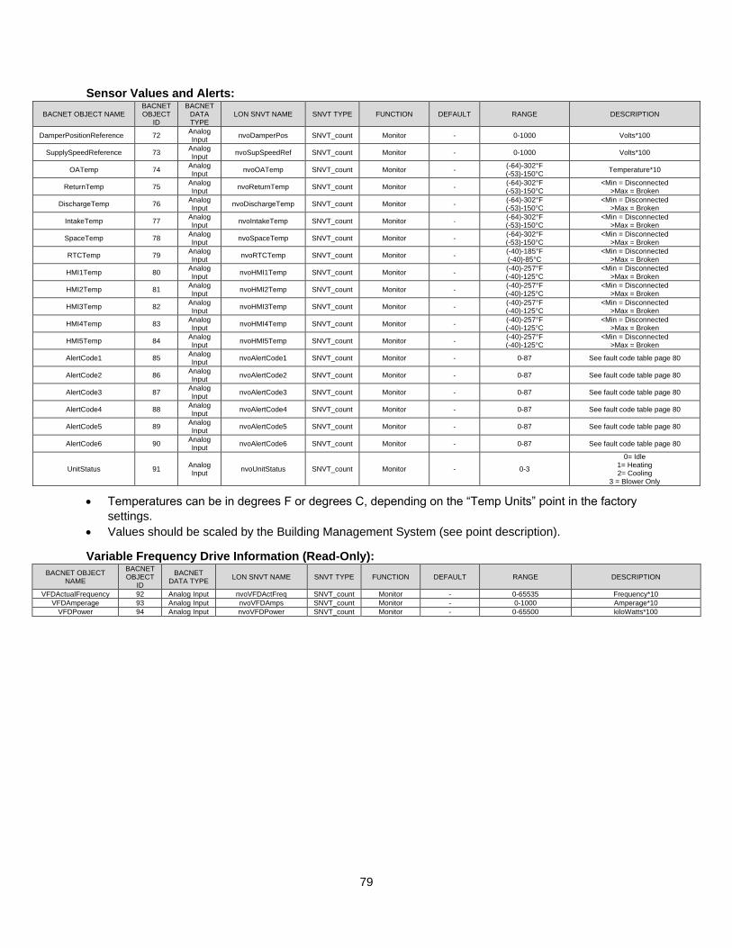
79
Sensor Values and Alerts:
• Temperatures can be in degrees F or degrees C, depending on the “Temp Units” point in the factory
settings.
• Values should be scaled by the Building Management System (see point description).
Variable Frequency Drive Information (Read-Only):
BACNET OBJECT NAME
BACNET OBJECT
ID
BACNET DATA TYPE
LON SNVT NAME SNVT TYPE FUNCTION
DEFAULT RANGE DESCRIPTION
VFDActualFrequency 92 Analog Input nvoVFDActFreq SNVT_count Monitor - 0-65535 Frequency*10
VFDAmperage 93 Analog Input nvoVFDAmps SNVT_count Monitor - 0-1000 Amperage*10
VFDPower 94 Analog Input nvoVFDPower SNVT_count Monitor - 0-65500 kiloWatts*100
BACNET OBJECT NAME BACNET OBJECT
ID
BACNET DATA TYPE
LON SNVT NAME SNVT TYPE FUNCTION DEFAULT RANGE DESCRIPTION
DamperPositionReference 72 Analog Input
nvoDamperPos SNVT_count Monitor - 0-1000 Volts*100
SupplySpeedReference 73 Analog Input
nvoSupSpeedRef SNVT_count Monitor - 0-1000 Volts*100
OATemp 74 Analog Input
nvoOATemp SNVT_count Monitor - (-64)-302°F (-53)-150°C
Temperature*10
ReturnTemp 75 Analog Input
nvoReturnTemp SNVT_count Monitor - (-64)-302°F (-53)-150°C
<Min = Disconnected >Max = Broken
DischargeTemp 76 Analog Input
nvoDischargeTemp SNVT_count Monitor - (-64)-302°F (-53)-150°C
<Min = Disconnected >Max = Broken
IntakeTemp 77 Analog Input
nvoIntakeTemp SNVT_count Monitor - (-64)-302°F (-53)-150°C
<Min = Disconnected >Max = Broken
SpaceTemp 78 Analog Input
nvoSpaceTemp SNVT_count Monitor - (-64)-302°F (-53)-150°C
<Min = Disconnected >Max = Broken
RTCTemp 79 Analog Input
nvoRTCTemp SNVT_count Monitor - (-40)-185°F (-40)-85°C
<Min = Disconnected >Max = Broken
HMI1Temp 80 Analog Input
nvoHMI1Temp SNVT_count Monitor - (-40)-257°F (-40)-125°C
<Min = Disconnected >Max = Broken
HMI2Temp 81 Analog Input
nvoHMI2Temp SNVT_count Monitor - (-40)-257°F (-40)-125°C
<Min = Disconnected >Max = Broken
HMI3Temp 82 Analog Input
nvoHMI3Temp SNVT_count Monitor - (-40)-257°F (-40)-125°C
<Min = Disconnected >Max = Broken
HMI4Temp 83 Analog Input
nvoHMI4Temp SNVT_count Monitor - (-40)-257°F (-40)-125°C
<Min = Disconnected >Max = Broken
HMI5Temp 84 Analog Input
nvoHMI5Temp SNVT_count Monitor - (-40)-257°F (-40)-125°C
<Min = Disconnected >Max = Broken
AlertCode1 85 Analog Input
nvoAlertCode1 SNVT_count Monitor - 0-87 See fault code table page 80
AlertCode2 86 Analog Input
nvoAlertCode2 SNVT_count Monitor - 0-87 See fault code table page 80
AlertCode3 87 Analog Input
nvoAlertCode3 SNVT_count Monitor - 0-87 See fault code table page 80
AlertCode4 88 Analog Input
nvoAlertCode4 SNVT_count Monitor - 0-87 See fault code table page 80
AlertCode5 89 Analog Input
nvoAlertCode5 SNVT_count Monitor - 0-87 See fault code table page 80
AlertCode6 90 Analog Input
nvoAlertCode6 SNVT_count Monitor - 0-87 See fault code table page 80
UnitStatus 91 Analog Input
nvoUnitStatus SNVT_count Monitor - 0-3
0= Idle 1= Heating 2= Cooling
3 = Blower Only
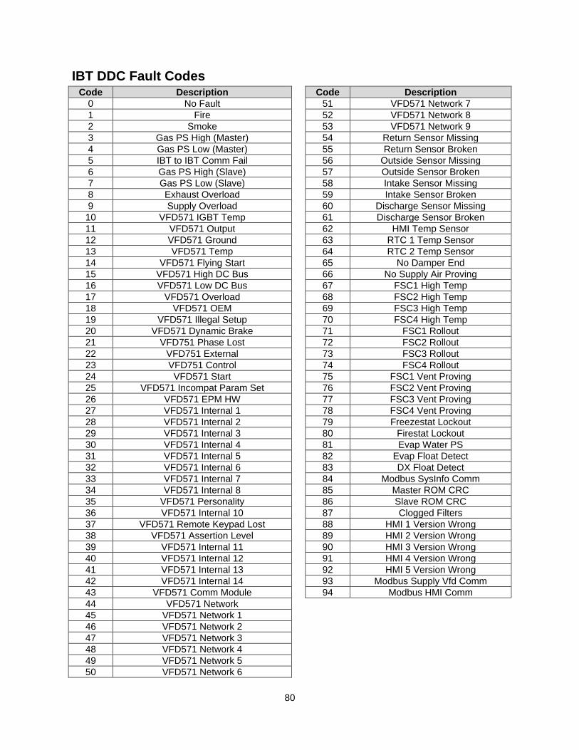
80
IBT DDC Fault Codes Code Description Code Description
0 No Fault 51 VFD571 Network 7
1 Fire 52 VFD571 Network 8
2 Smoke 53 VFD571 Network 9
3 Gas PS High (Master) 54 Return Sensor Missing
4 Gas PS Low (Master) 55 Return Sensor Broken
5 IBT to IBT Comm Fail 56 Outside Sensor Missing
6 Gas PS High (Slave) 57 Outside Sensor Broken
7 Gas PS Low (Slave) 58 Intake Sensor Missing
8 Exhaust Overload 59 Intake Sensor Broken
9 Supply Overload 60 Discharge Sensor Missing
10 VFD571 IGBT Temp 61 Discharge Sensor Broken
11 VFD571 Output 62 HMI Temp Sensor
12 VFD571 Ground 63 RTC 1 Temp Sensor
13 VFD571 Temp 64 RTC 2 Temp Sensor
14 VFD571 Flying Start 65 No Damper End
15 VFD571 High DC Bus 66 No Supply Air Proving
16 VFD571 Low DC Bus 67 FSC1 High Temp
17 VFD571 Overload 68 FSC2 High Temp
18 VFD571 OEM 69 FSC3 High Temp
19 VFD571 Illegal Setup 70 FSC4 High Temp
20 VFD571 Dynamic Brake 71 FSC1 Rollout
21 VFD751 Phase Lost 72 FSC2 Rollout
22 VFD751 External 73 FSC3 Rollout
23 VFD751 Control 74 FSC4 Rollout
24 VFD571 Start 75 FSC1 Vent Proving
25 VFD571 Incompat Param Set 76 FSC2 Vent Proving
26 VFD571 EPM HW 77 FSC3 Vent Proving
27 VFD571 Internal 1 78 FSC4 Vent Proving
28 VFD571 Internal 2 79 Freezestat Lockout
29 VFD571 Internal 3 80 Firestat Lockout
30 VFD571 Internal 4 81 Evap Water PS
31 VFD571 Internal 5 82 Evap Float Detect
32 VFD571 Internal 6 83 DX Float Detect
33 VFD571 Internal 7 84 Modbus SysInfo Comm
34 VFD571 Internal 8 85 Master ROM CRC
35 VFD571 Personality 86 Slave ROM CRC
36 VFD571 Internal 10 87 Clogged Filters
37 VFD571 Remote Keypad Lost 88 HMI 1 Version Wrong
38 VFD571 Assertion Level 89 HMI 2 Version Wrong
39 VFD571 Internal 11 90 HMI 3 Version Wrong
40 VFD571 Internal 12 91 HMI 4 Version Wrong
41 VFD571 Internal 13 92 HMI 5 Version Wrong
42 VFD571 Internal 14 93 Modbus Supply Vfd Comm
43 VFD571 Comm Module 94 Modbus HMI Comm
44 VFD571 Network
45 VFD571 Network 1
46 VFD571 Network 2
47 VFD571 Network 3
48 VFD571 Network 4
49 VFD571 Network 5
50 VFD571 Network 6
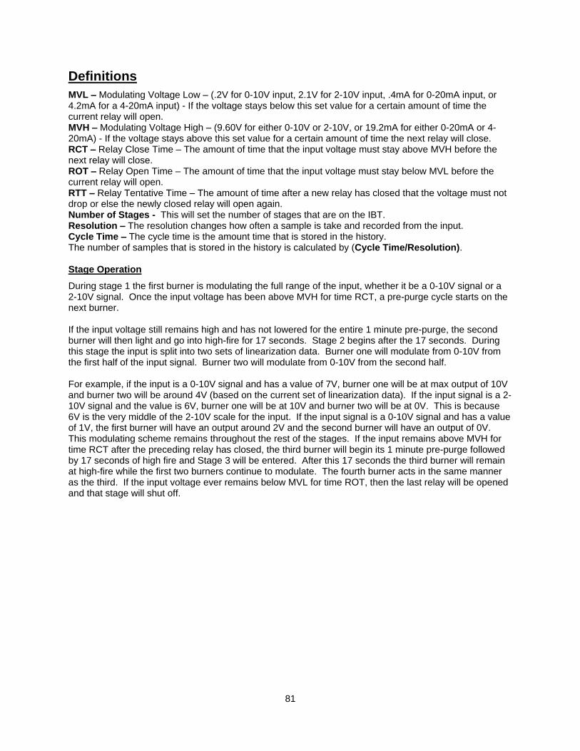
81
Definitions
MVL – Modulating Voltage Low – (.2V for 0-10V input, 2.1V for 2-10V input, .4mA for 0-20mA input, or 4.2mA for a 4-20mA input) - If the voltage stays below this set value for a certain amount of time the current relay will open. MVH – Modulating Voltage High – (9.60V for either 0-10V or 2-10V, or 19.2mA for either 0-20mA or 4-20mA) - If the voltage stays above this set value for a certain amount of time the next relay will close. RCT – Relay Close Time – The amount of time that the input voltage must stay above MVH before the next relay will close. ROT – Relay Open Time – The amount of time that the input voltage must stay below MVL before the current relay will open. RTT – Relay Tentative Time – The amount of time after a new relay has closed that the voltage must not drop or else the newly closed relay will open again. Number of Stages - This will set the number of stages that are on the IBT. Resolution – The resolution changes how often a sample is take and recorded from the input. Cycle Time – The cycle time is the amount time that is stored in the history. The number of samples that is stored in the history is calculated by (Cycle Time/Resolution). Stage Operation
During stage 1 the first burner is modulating the full range of the input, whether it be a 0-10V signal or a 2-10V signal. Once the input voltage has been above MVH for time RCT, a pre-purge cycle starts on the next burner. If the input voltage still remains high and has not lowered for the entire 1 minute pre-purge, the second burner will then light and go into high-fire for 17 seconds. Stage 2 begins after the 17 seconds. During this stage the input is split into two sets of linearization data. Burner one will modulate from 0-10V from the first half of the input signal. Burner two will modulate from 0-10V from the second half. For example, if the input is a 0-10V signal and has a value of 7V, burner one will be at max output of 10V and burner two will be around 4V (based on the current set of linearization data). If the input signal is a 2-10V signal and the value is 6V, burner one will be at 10V and burner two will be at 0V. This is because 6V is the very middle of the 2-10V scale for the input. If the input signal is a 0-10V signal and has a value of 1V, the first burner will have an output around 2V and the second burner will have an output of 0V. This modulating scheme remains throughout the rest of the stages. If the input remains above MVH for time RCT after the preceding relay has closed, the third burner will begin its 1 minute pre-purge followed by 17 seconds of high fire and Stage 3 will be entered. After this 17 seconds the third burner will remain at high-fire while the first two burners continue to modulate. The fourth burner acts in the same manner as the third. If the input voltage ever remains below MVL for time ROT, then the last relay will be opened and that stage will shut off.
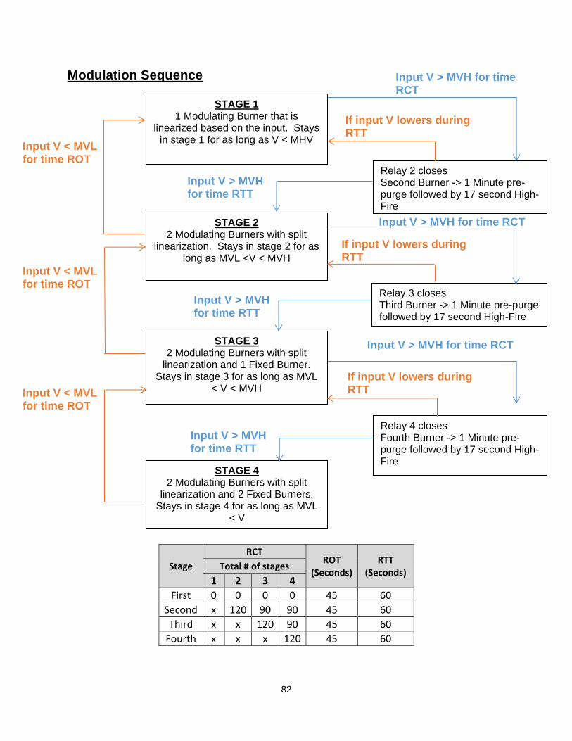
82
Modulation Sequence
Stage
RCT ROT
(Seconds) RTT
(Seconds) Total # of stages
1 2 3 4
First 0 0 0 0 45 60
Second x 120 90 90 45 60
Third x x 120 90 45 60
Fourth x x x 120 45 60
Input V > MVH for time RCT STAGE 1
1 Modulating Burner that is linearized based on the input. Stays
in stage 1 for as long as V < MHV
STAGE 2 2 Modulating Burners with split
linearization. Stays in stage 2 for as long as MVL <V < MVH
STAGE 3 2 Modulating Burners with split
linearization and 1 Fixed Burner. Stays in stage 3 for as long as MVL
< V < MVH
STAGE 4 2 Modulating Burners with split
linearization and 2 Fixed Burners. Stays in stage 4 for as long as MVL
< V
Relay 2 closes Second Burner -> 1 Minute pre-purge followed by 17 second High-Fire
Input V > MVH for time RCT
Relay 3 closes Third Burner -> 1 Minute pre-purge followed by 17 second High-Fire
Relay 4 closes Fourth Burner -> 1 Minute pre-purge followed by 17 second High-Fire
If input V lowers during RTT
If input V lowers during RTT
Input V > MVH for time RCT
If input V lowers during RTT
Input V < MVL for time ROT
Input V < MVL for time ROT
Input V < MVL for time ROT
Input V > MVH for time RTT
Input V > MVH for time RTT
Input V > MVH for time RTT

83
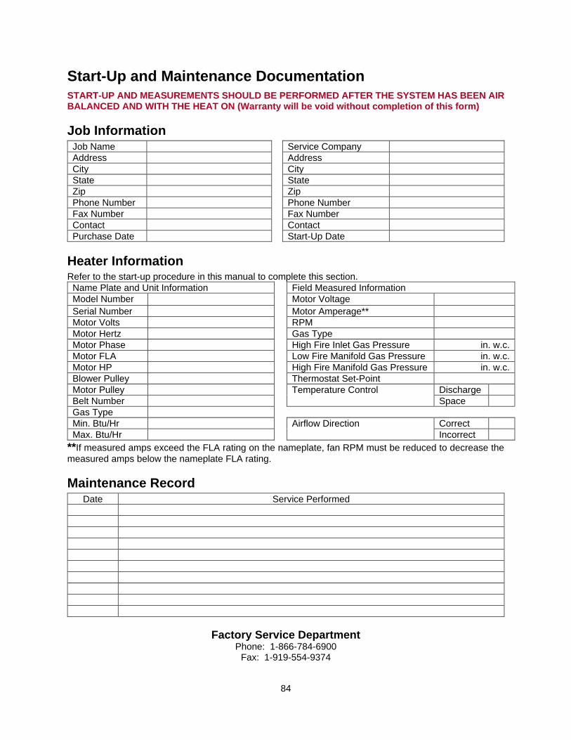
84
Start-Up and Maintenance Documentation START-UP AND MEASUREMENTS SHOULD BE PERFORMED AFTER THE SYSTEM HAS BEEN AIR BALANCED AND WITH THE HEAT ON (Warranty will be void without completion of this form)
Job Information Job Name Service Company
Address Address
City City
State State
Zip Zip
Phone Number Phone Number
Fax Number Fax Number
Contact Contact
Purchase Date Start-Up Date
Heater Information Refer to the start-up procedure in this manual to complete this section.
Name Plate and Unit Information Field Measured Information
Model Number Motor Voltage Serial Number Motor Amperage**
Motor Volts RPM
Motor Hertz Gas Type
Motor Phase High Fire Inlet Gas Pressure in. w.c.
Motor FLA Low Fire Manifold Gas Pressure in. w.c.
Motor HP High Fire Manifold Gas Pressure in. w.c.
Blower Pulley Thermostat Set-Point
Motor Pulley Temperature Control Discharge
Belt Number Space
Gas Type
Min. Btu/Hr Airflow Direction Correct
Max. Btu/Hr Incorrect
**If measured amps exceed the FLA rating on the nameplate, fan RPM must be reduced to decrease the
measured amps below the nameplate FLA rating.
Maintenance Record Date Service Performed
Factory Service Department Phone: 1-866-784-6900
Fax: 1-919-554-9374