modular wiper control lms - liemo.nl · the green group status led’s does indicate the active...
TRANSCRIPT

Modular Wiper Control LMS
Installation and operation manual
www.speich.it
UK

Speich S.r.l. Pag.2 Modular Wiper Control - LMS

Speich S.r.l. Pag.3 Modular Wiper Control - LMS
CONTENT:
1 PRODUCT DESCRIPTION .................................................................................................................. 4 1.1 Package content......................................................................................................................... 4
2 OPERATION ........................................................................................................................................ 5 2.1 Explanation wipe program led bar display (yellow) ....................................................................... 5 2.2 Explanation group-status led bar display (green) .......................................................................... 5 2.3 Group switches .............................................................................................................................. 6 2.4 On/Off switch ................................................................................................................................. 6 2.5 Wipe program switch ..................................................................................................................... 6 2.6 Washer program switch ................................................................................................................. 6 2.7 One or two panels.......................................................................................................................... 6
3 FUNCTION POWER MODULE............................................................................................................ 7 3.1 Explanation of the power module .................................................................................................. 7 3.2 Protections ..................................................................................................................................... 7 3.3 Park terminals ................................................................................................................................ 7 3.4 High speed terminal ....................................................................................................................... 7 3.5 Low speed terminal........................................................................................................................ 8 3.6 Washer terminal............................................................................................................................. 8 3.7 + In terminal ................................................................................................................................... 8 3.8 Gnd terminal .................................................................................................................................. 8 3.9 Link connectors (modular Rj12)..................................................................................................... 8
4 INSTALLATION ................................................................................................................................... 9 4.1 Installation Power Module.............................................................................................................. 9 4.2 Installation control panel(s) .......................................................................................................... 10 4.3 System initialization ..................................................................................................................... 11
5 DIMENSIONS..................................................................................................................................... 12 6 CONNECTION DIAGRAMS............................................................................................................... 13 7 TROUBLESHOOTING....................................................................................................................... 17 8 TECHNICAL INFORMATION ............................................................................................................ 18
8.1 Technical specifications of the power module ............................................................................. 18 8.2 Technical specifications of the control panel ............................................................................... 18
9 CE DECLARATION OF CONFIRMITY.............................................................................................. 19

Speich S.r.l. Pag.4 Modular Wiper Control - LMS
1 PRODUCT DESCRIPTION
The modular wiper control system (LMS)
consists of two basic components; The Power
Module and the control panel. The modular
system is very flexible because it can be
expanded depending upon the number of
wipers installed. The system can be expanded
to a maximum of 3 power modules (max.9
wipers) and two control panels.
The modular wiper control is developed for
“heavy duty” wiper motors, the Speich LP type
motor. Also smaller wiper motors can be
installed, if they are equipped with one speed
and self parking function or two speeds and
self parking function.
The system contains an intelligent washer
program and a total of five wipe programs. The
washer program will pre-wash the
windscreens, wash and wipe and then wipe
three times to dry up the windscreens. The five
wipe programs are:
- High speed synchronized;
- Low speed synchronized;
- Low speed, interval 2.5 sec;
- Low speed, interval 5.0 sec;
- Low speed, interval 10 sec;
The wiper movement is synchronized at all
speeds!
For the power control of the system ‘solid-
state’ switching techniques are used. This
means there are no moving parts and therefore
no noise is coming from the electronics. Also
there is no wear and tear of relays, which will
increase the expected lifespan of the
electronics used for the Modular wiper control.
The modular wiper control system operates on
a supply voltage between 10 – 30 V DC.
1.1 Package content
The package consists of:
- This manual;
- Wiper control, power module;
- Wiper control, control panel;
- Rj12 modular cable (5m);
- 4 stainless steel M4 bolts + nuts;
- 4 stainless steel screws.
Speich S.r.l. Pag.5 Modular Wiper Control - LMS
2 OPERATION The LMS system can be controlled by means
of one or two installed control panels. In
chapter 4 the installation of the modular
system is explained.
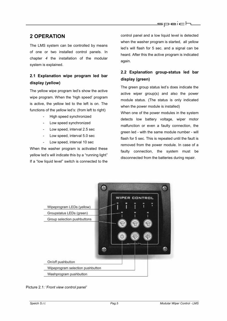
2.1 Explanation wipe program led bar display (yellow)
The yellow wipe program led’s show the active
wipe program. When the ‘high speed’ program
is active, the yellow led to the left is on. The
functions of the yellow led’s: (from left to right)
- High speed synchronized
- Low speed synchronized
- Low speed, interval 2.5 sec
- Low speed, interval 5.0 sec
- Low speed, interval 10 sec
When the washer program is activated these
yellow led’s will indicate this by a “running light”
If a “low liquid level” switch is connected to the
control panel and a low liquid level is detected
when the washer program is started, all yellow
led’s will flash for 5 sec. and a signal can be
heard. After this the active program is indicated
again.
2.2 Explanation group-status led bar display (green)
The green group status led’s does indicate the
active wiper group(s) and also the power
module status. (The status is only indicated
when the power module is installed)
When one of the power modules in the system
detects low battery voltage, wiper motor
malfunction or even a faulty connection, the
green led - with the same module number - will
flash for 5 sec. This is repeated until the fault is
removed from the power module. In case of a
faulty connection, the system must be
disconnected from the batteries during repair.
Picture 2.1: ‘Front view control panel’

Speich S.r.l. Pag.6 Modular Wiper Control - LMS
2.3 Group switches
With the 3 group switches the corresponding
groups can be switched on and off. The green
led’s above the numbered switches indicate
the active wiper group(s).
2.4 On/Off switch
With this switch the system can be switched on
and off. If the washer program is running when
this switch is operated, the washer program
will be terminated.
2.5 Wipe program switch
When this switch is operated repeatedly, the
desired wipe program can be activated. De
active wipe program is indicated by one of the
yellow wipe program led’s.
2.6 Washer program switch
When the system is off and the washer
program is activated by pressing the washer
program switch, the system will start a wash
and wipe program. The program executes a
pre-wash then wash and wipe and concludes
with three wipe movements to dry up the
windscreens.
When the system is on and the washer
program is activated, the system will wash and
wipe three wipe movements.
2.7 One or two panels
The modular wiper control system is installed
with a minimum of 1 control panel, following
the installation directions in chapter 4.
A 2nd control panel enables the user to control
from another position.
In case 2 panels are installed in the correct
way, the functionality of both panels will
automatically be the same. Please follow the
installation directions in chapter 4.

Speich S.r.l. Pag.7 Modular Wiper Control - LMS
3 FUNCTION POWER MODULE The function of the power module is handled in
this chapter. The installation of the power
module is explained in chapter 4.
3.1 Explanation of the power module
The supply voltage of the system coming from
the batteries is connected to the power
module(s). The module detects the nominal
supply voltage 12 / 24 V at initialization. All
wiper motors and washer pumps or valves
must have to operate with the same nominal
voltage 12 / 24 V
The control panel is connected to the first
power module with a 6 pole RJ12/RJ12 cable
of 5 meters. All information about the active
programs or failures is displayed on the control
panel The power modules are also controlled
from the control panel.
3.2 Protections
Inside the power module a number of blade
fuses are positioned. All outputs are protected
by a 10A ATO blade fuse and the washer
output is protected by a 5A ATO blade fuse. If
a fuse must be replaced after an overload of
any kind, one of the plastic side panels can be
removed by an experienced person. After
removing the side panel the front plate can be
removed to be able to reach the fuses. (see
picture 6.5: ‘Internal fuses power module’)
3.3 Park terminals
The park connection of the wiper motor has to
be connected to the park connection on the
power module
3.4 High speed terminal
The high speed output must be connected to
the high speed connection of the wiper motor.
For when the wiper motor has got two speeds.
CAUTION!
Do not exchange the ‘slow’ and the ‘fast’
connections.
Picture 3.2: ‘Power module front view’

Speich S.r.l. Pag.8 Modular Wiper Control - LMS
3.5 Low speed terminal
The low speed connection of the power
module has to be connected to the low speed
connection on the wiper motor.
CAUTION! Do not exchange the ‘slow’ and the ‘fast’
connections.
3.6 Washer terminal
The washer pump / valve can be connected to
the washer terminal.
3.7 + In terminal
The power supply + has to be connected to
one of the two + in terminals. These terminals
are internally connected to each other. The
second + in terminal can be connected to the
next power module.
3.8 Gnd terminal
The ground of the power supply has to be
connected to one of the two gnd terminals.
These two gnd terminals are internally
connected to each other. The second gnd
terminal can be connected to the next power
module.
3.9 Link connectors (modular Rj12)
The link in and out connectors can be used to
connect the control panel and the power
modules. This is a standard 6-pole RJ12
connector.

Speich S.r.l. Pag.9 Modular Wiper Control - LMS
4 INSTALLATION Make sure the batteries are disconnected
before installation of the system. Also make
sure the nominal voltage of all wiper motors,
valves and pumps are the same as the
nominal battery voltage 12 / 24 V. Use proper
wiring with sufficient cupper diameter to
prevent malfunction of the system in normal
operation. Use quality tools to make the crimp
connections to the wiring. Only use wiper
motors of the same brand and type to ensure a
smooth operation of the system.
Note:
When wiper motors are very cold or have not
been used for a long period of time,
synchronization of the wipers may not work for
several wiper movements. After a short period
the movement of all wipers should be
synchronized.
Safety measures:
- Use wiring with sufficient cupper diameter;
- Install the system in a dry and well ventilated
space;
- NEVER use the system on locations where
any danger of explosions exists;
- Use the connections and protections
according to the appropriate regulations;
- Make sure the system is installed with a main
fuse in the supply line;
- Check the wiring and connections at least
once a year and replace doubtful wiring
immediately;
- The manufacturer of this product does not
accept any responsibility for damage of any
kind, caused by the use of the product.
4.1 Installation Power Module
Mount the power module on a flat and solid
base. Make very sure all connections are
made properly and only use quality tools.
4.1.1 Connect the supply voltage
Make sure the supply current from the
batteries is transferred to the system through
wiring with sufficient cupper diameter. The
starting currents of the wiper motors can run
up to 35 Amps. each. Use the same diameter
for the + and – battery connection. Connect +
battery 12 / 24 V to 1 of the + connections on
the power module and connect the ground of
the battery to 1 of the ground terminals (GND)
of the power module
The 2nd + and GND terminals on the power
modules can be used to connect the next
power module to the batteries, without the
need of extra wiring coming from the batteries.
4.1.2 Connect the wiper motors
Up to 3 wiper motors can be connected to a
single power module. The modular wiper
control is developed for “heavy duty” wiper
motors, the Speich LP type motor. Also smaller
wiper motors can be installed, if they are
equipped with one speed and self parking
function or two speeds and self parking
function. When use of the high speed function
of some wiper motors is not advisable, simply
do not connect this wire to the power module.
Connect the self parking or “park” wire of wiper
motor 1 to the park 1 terminal on the power
module. (see Picture 6.3: Wiper motor 1
connections to the power module.) Connect
the high speed or “fast” wire of wiper motor 1
to the fast 1 terminal on the power module.
Connect the low speed or “slow” wire of wiper

Speich S.r.l. Pag.10 Modular Wiper Control - LMS
motor 1 to the slow 1 terminal on the power
module. Connect wiper motor 2 and 3 in the
same order. The ground terminal of each wiper
motor must be connected to a common ground
terminal in the installation.
4.1.3 Connect the washer pump or valve
A water pump or electric mechanical valve can
be connected to the washer output on the
power module. This output can supply a
continuous current of 5A max. The ground
terminal of the water pump or valve must be
connected to a common ground terminal in the
installation.
(see Picture 6.4: ‘Washer connection’)
4.1.4 Power modules ‘linked’
A maximum of 3 power modules can be linked
in the modular wiper control system. A 5 meter
RJ12/RJ12 6pole cable is supplied for the link
between all power modules and control
panel(s). The connections are indicated in
picture 6.1: ‘Possible configurations’ and in
picture 6.2: ‘Example of supply voltage
connection’. It is very important to follow the
“link in” and “link out” directions accurately.
Control panel 1 - Power module 1:
Connect a RJ12/RJ12 cable between ‘Link’ on
control panel 1 and ‘Link in’ on power module
1.
Power module 1- Power module 2:
Connect a RJ12/RJ12 cable between ‘Link out’
on power module 1 and ‘Link in’ on power
module 1.
Power module 2- Power module 3:
Connect a RJ12/RJ12 cable between ‘Link out’
on power module 2 and ‘Link in’ on power
module 3.
Power module 3 – Control panel 2:
Connect a RJ12/RJ12 cable between ‘Link out’
on power module 3 and ‘Link’ on control panel
2.
All supplied RJ12/RJ12 cables are 1:1 pre-
wired and 5 meters long. If necessary the
cable can be shortened. The advised
maximum cable length is 10 meters.
4.2 Installation control panel(s)
Install the control panel(s) on a suitable
position. The diameter for mounting hole of the
panel is 75mm. Mount the panel with the
screws or bolts supplied with the modular
wiper control system. Remove the panel on the
back of the control panel housing and connect
the cables.
4.2.1 One or two control panel installation
The system can be controlled with either one
or two control panels. In larger installations or
in case of 2 steering positions a 2nd control
panel is installed. In case of only one control
panel, no adjustments are made during
installation. In case of 2 control panels, the 2nd
control panel connected to “link out” of power
module 1, 2 or 3, a jumper setting must be
made. The jumper called “control panel” at the
back of the electronics of the panel must be set
to position 2. (Picture 6.6: ‘Control panel
connections’)
4.2.2 Connect the control panel(s)
Control panel 1 is connected to “link in” of
power module 1 with the RJ12/RJ12 cable.
The cable is used for the communication
between all modules of the modular wiper
control system and also the supply voltage for
the panel is drawn from it. The optional 2nd

Speich S.r.l. Pag.11 Modular Wiper Control - LMS
control panel is connected to “link out” of
power module 1, 2 or 3 (the last power
module) with an RJ12/RJ12 cable. (Picture 6.6:
‘Control panel connections’)
4.2.3 Connect the 'low liquid level switch'
On the back of the electronics of the control
panel a faston terminal for the low liquid level
switch is positioned. Connect the “normally
open” switch of the water tank to this terminal.
Connect the other side of the switch to a
common ground terminal in the installation.
When the washer program is activated on the
control panel and the switch is closed because
a low liquid level is detected, all yellow led’s
will flash for 5 sec. and a signal can be heard.
After this “low liquid level alarm” the active
program is indicated again. (Picture 6.6:
‘Control panel connections’)
4.2.4 Connect the “foot” switch
On the back of the electronics of the control
panel a faston terminal for the “foot” switch or
other external pushbutton switch is positioned.
Connect the “normally open” switch to this
terminal. Connect the other side of the switch
to a common ground terminal in the
installation. When the switch is operated when
the system is off or when one of the interval
programs is active, all connected wipers will
have 1 wipe movements. After the last wiper
movement the previously active program is
indicated again. (Picture 6.6: ‘Control panel
connections’)
4.3 System initialization
When the supply voltage coming from the
batteries is connected to the system, it will
automatically detect the system voltage 12 / 24
V. Also a full automatic initialization of the
system will determine the amount of power
modules (1 – 3) and control panels (1 – 2)
have been connected in the modular wiper
control system.
4.3.1 Group configuration option
The standard group configuration can be
adapted after initialization. The group
configuration option only works when more
than 1 power module is connected to the
system. This option enables the possibility to
install the power modules closest to the wiper
motors. Very long wiring can be prevented with
this option. By pressing the wiper group 1
switch for more than 10 sec. the group
configuration is changed. A signal confirms the
change of this setting.
The standard group configuration is:
Each power module can control 3 wiper motors
Each power module controls a wiper motor in 3
different wiper groups, group 1, group 2 and
group. The wiper groups are activated and
deactivated with the group switches on the
control panel. (Picture 6.7: ‘group
configuration’)
The optional group configuration is:
Each power module controls all wiper motors
of the same group. This means; power module
1 controls all wiper motors of group 1,
activated or deactivated by the group 1 switch
on the control panel. Group 1 can now control
for example the complete starboard side of the
installation, group 2 the centre and group 3 the
port side. This way the power modules are
installed nearest to the wiper motors. (Picture
6.7: ‘group configuration’)

Speich S.r.l. Pag.12 Modular Wiper Control - LMS
5 DIMENSIONS
Picture 5.1: ‘Dimensions control panel’
Picture 5.2: ‘Dimensions power module’

Speich S.r.l. Pag.13 Modular Wiper Control - LMS
6 CONNECTION DIAGRAMS A 2nd control panel is possible in any configuration, with 1, 2 or 3 power modules.
Basic configuration 1-3 wiper motors Configuration 4-6wiper motors
Configuration 7-9 wiper motors
Picture 6.1: ‘Possible configurations’

Speich S.r.l. Pag.14 Modular Wiper Control - LMS
Picture 6.2: ‘Example of the supply voltage connection’
Picture 6.3: ‘Wiper motor 1 connections to the power module. (motor 2 & 3 connections are similar)’
Picture 6.4: ‘Washer connection’

Speich S.r.l. Pag.15 Modular Wiper Control - LMS
Picture 6.5: ‘Internal fuses power module’
Picture 6.6: ‘Control panel connections’

Speich S.r.l. Pag.16 Modular Wiper Control - LMS
Standard group configuration
Optional group configuration
Picture 6.7: ‘group configuration’
(is set when after installation ‘group 1’ button is pressed for 10 sec.)

Speich S.r.l. Pag.17 Modular Wiper Control - LMS
7 TROUBLESHOOTING
Problem / Signal Cause Solve - Led Group 1, 2 or 3 on the control panel blinks - Wipers do not move
Low battery / system voltage on power module 1, 2 or 3
Charge the system battery
- Led Group 1, 2 or 3 on the control panel blinks - Wipers do not move
Bad or loose wring on power module 1, 2 or 3
Make the system power less and check the wiring and connections.
- one wiper stops moving Bad wiring or loose contact
Make the system power less and check the wiring and connections.
- one wiper stops moving Fuse has blown (wiper could been frozen to the window)
Check (replace) the defective fuse (chapter 3.2)
- washer does not work and no low liquid level signal.
Fuse may be defect, because of overload or short circuit.
Check (replace) the defective fuse (chapter 3.2)
- after installation the system does not operate, and system voltage is measured on the + in terminal(s).
Control panel modular cable connection or jumper setting could be wrong.
Check the RJ12 modular cable, is it connected to the right ‘link’ connector? Check the jumper setting inside the control panel. (chapter 4.2)

Speich S.r.l. Pag.18 Modular Wiper Control - LMS
8 TECHNICAL INFORMATION
8.1 Technical specifications of the power module
Supply voltage : 10 - 30 V DC
Stand by power consumption : < 0,2 W
Max. load / wiper output : 10A cont. 20A int.
Max. load washer output : 5A cont. 10A int.
Operating temperature : -10 to +60˚ C (+14 to +140˚ F)
Storage temperature : -40 to +70˚ C ( -22 to +158˚ F)
Connections : Battery + and battery ground.
3 x self parking connection, fast and slow
wiper motor connection, washer pump / valve
connection
2 x modular cable RJ12/RJ12, L = 5 meters.
Protections wiper output : Blade fuse 10A (ATO)
Protections washer output : Blade fuse 5A (ATO)
Dimensions : 146 x 67 x 97 mm ( l x w x h )
Weight : 415 gram.
8.2 Technical specifications of the control panel
Operating temperature : -10 to +60˚ C (+14 to +140˚ F)
Storage temperature : -40 to +70˚ C ( -22 to +158˚ F)
Connections : modular cable RJ12/J12, L = 5 meters.
Low liquid level input (switch to ground, N.O.)
(Foot) switch input
Stand by power consumption : < 0,14 W
Type : IP.. dashboard housing
Drill hole size : Ø 75 mm
Dimensions : 90 x 90 x 47 mm ( h x w x d )
Weight : 100 gram

Speich S.r.l. Pag.19 Modular Wiper Control - LMS
9 CE DECLARATION OF CONFIRMITY
Manufacturer: LieMo electronics
Address: Lijnbaanstraat 1
9711 RT Groningen
The Netherlands
Declares that:
Product: Modular Wiper Control LMS
Is in conformity with the provision of the EEC directive EMC 89/336/EEG
and amendments 92/31/EEG and 93/68/EEG.
The following harmonized standards have been applied:
Emission: EN 50081-1:1992
Immunity: EN 50082-1:1992
Safety: EN 60950-1:1992
Groningen,
P. van der Molen
LieMo electronics

Speich S.r.l. Pag.20 Modular Wiper Control - LMS
SPEICH s.r.l. Via G.Adamoli, 443 16141 Genova – Italy Phone: +39.010.8380676 Fax: +39.010.8468449 Web: www.speich.com E-mail: [email protected]