modulating control valve sizing and selection -...
TRANSCRIPT

Workshop NotesModulating Control Valve
Sizing and Selection
R
CONTROLS
Workshop Notes: Modulating Control Valve Sizing Selection
BraySize BII Sizing V2.0.1 Dated: 06/Jan/2014
Roger Barnes -‐1/20/2014
1. Open Program – select new project XXXX Workshop Jan xx 2. Demo – Project settings
a. Affects the next line item valves only, not the currently opened line item i. Default units (metric & Imperial can be mixed, individual line items can be
different ) ii. Degree or % of stroke
1. Min/Max setting, only sets warnings level a. 20 to 80 % or degrees good starting point
iii. Noise warning limit (suggest 90) 3. Demo assigning tag line item
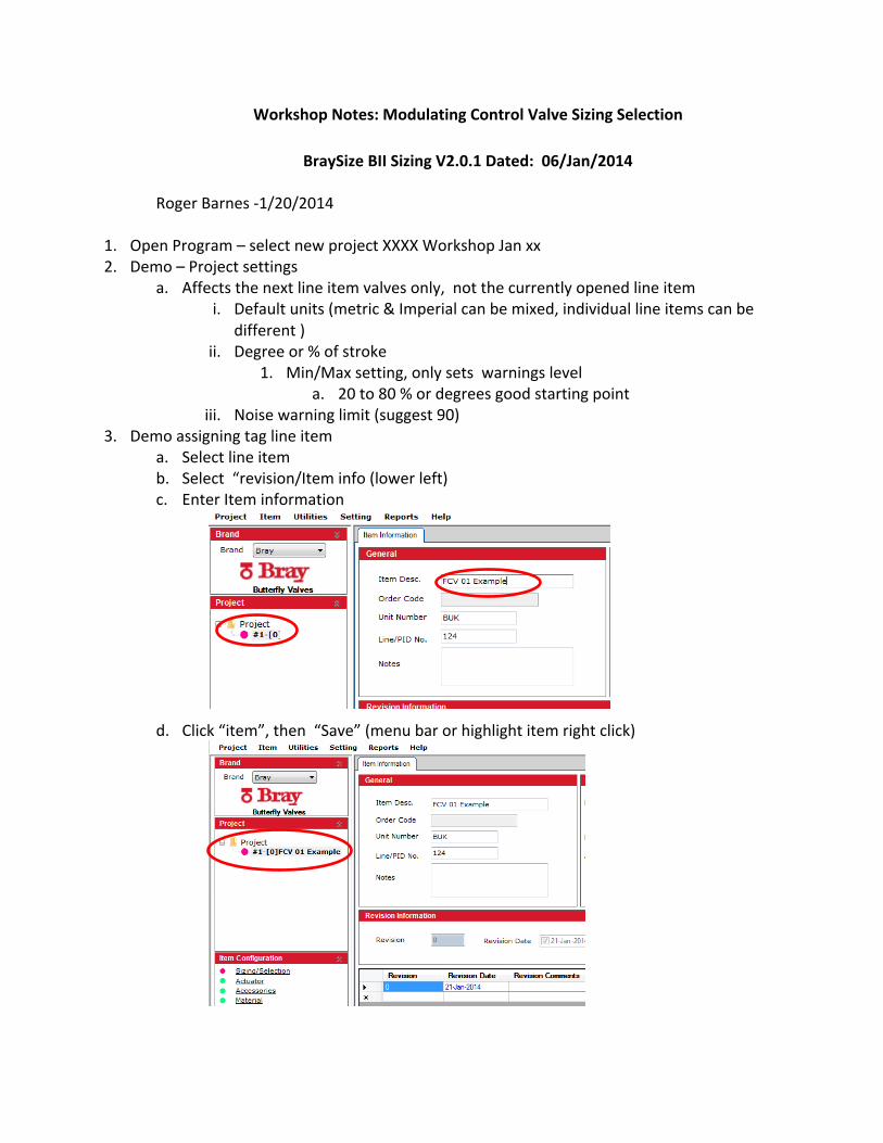
a. Select line item b. Select “revision/Item info (lower left) c. Enter Item information
d. Click “item”, then “Save” (menu bar or highlight item right click)

4. Enter process data for Example (approximate conditions from “real world” examples from module 6 Flow Characteristics, water, 10” line) press “calculate”
5. Demo change in Shut Off ΔP & Design Press – Impacts actuator only
a. Note Following i. Shut off ΔP – defaults to the highest P1 ii. Impacts actuator sizing only
1. Change to 150 psi 2. Note that it changes Design pressure, Can still select a Series 21 for
example

6. Demo design pressure a. Design Pressure(and Design Pressure) – defaults to highest P1 or shut off
i. Impact valve pressure class selections ii. Change to 151 psi iii. Now cannot select S21 only S31 iv. Note! If you change service conditions these values do not reset
automatically – must be done manually
7. Explained “Valve Selection” (power point slide # 7)
a. “Selection Criteria” is a filter b. BraySize defaults to line size valve (not always the best choice)
8. Try Select 10’ S21, Click “Re Calc” (PP slide #8) Note now red “Re Calc” not “Calculate’ a. Note red % “opening degree” warning
9. Check flow curve – Click “item” (menu bar), “Flow curve” a. Operating too close to seat
i. 20% is rule of thumb not a hard fast rule
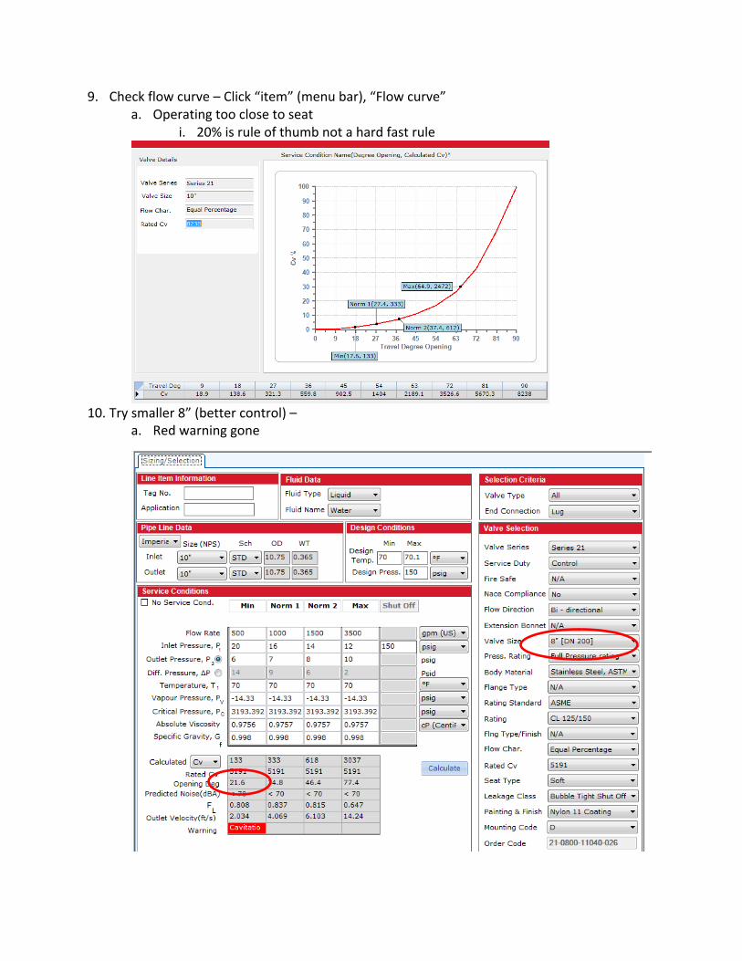
10. Try smaller 8” (better control) –
a. Red warning gone
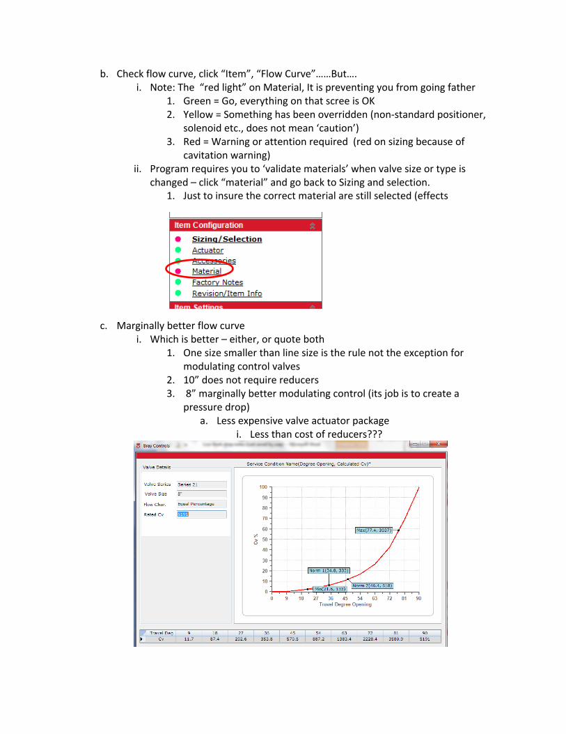
b. Check flow curve, click “Item”, “Flow Curve”……But…. i. Note: The “red light” on Material, It is preventing you from going father
1. Green = Go, everything on that scree is OK 2. Yellow = Something has been overridden (non-‐standard positioner,
solenoid etc., does not mean ‘caution’) 3. Red = Warning or attention required (red on sizing because of
cavitation warning) ii. Program requires you to ‘validate materials’ when valve size or type is
changed – click “material” and go back to Sizing and selection. 1. Just to insure the correct material are still selected (effects
c. Marginally better flow curve i. Which is better – either, or quote both
1. One size smaller than line size is the rule not the exception for modulating control valves
2. 10” does not require reducers 3. 8” marginally better modulating control (its job is to create a
pressure drop) a. Less expensive valve actuator package
i. Less than cost of reducers???

11. What about cavitation warning ????-‐Cavitation application is both a Science and Art
a. Lots of factors affect decision – Warning might not mean there is a problem i. Startup condition only?
1. Might be Ok but probably not if continuous operating point (damage is time dependent, short term exposure is OK )
ii. Cavitation calculation very very sensitive to P2 1. Change P2 from 6 to 7, one psi change is enough switch off the
warning. Ask customer to verfy P2 iii. Change P1 from 20 to 18
1. Cavitation less sensitive to P1 (required 2 psi change) iv. Double check temperature (cavitation sensitive to high temp)
1. Make sure using actual operating temperature not max design temp
12. Try a ball valve to solve Cavitation problem a. Left click on line item, select “Duplicate”
i. Keeps process data and valve selections b. Change Brand to FlowTek
i. Keeps Service Conditions, defaults everything else.
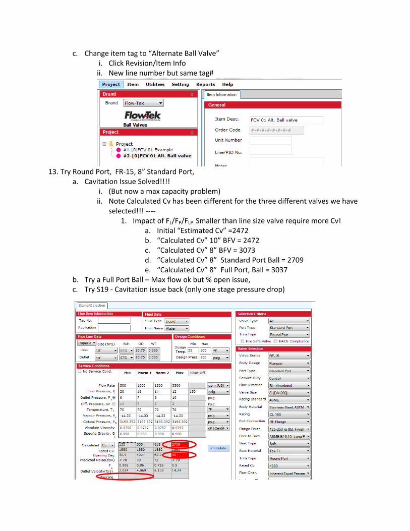
c. Change item tag to “Alternate Ball Valve” i. Click Revision/Item Info ii. New line number but same tag#
13. Try Round Port, FR-‐15, 8” Standard Port,
a. Cavitation Issue Solved!!!! i. (But now a max capacity problem) ii. Note Calculated Cv has been different for the three different valves we have
selected!!! -‐-‐-‐-‐ 1. Impact of FL/FP/FLP: Smaller than line size valve require more Cv!
a. Initial “Estimated Cv” =2472 b. “Calculated Cv” 10” BFV = 2472 c. “Calculated Cv” 8” BFV = 3073 d. “Calculated Cv” 8” Standard Port Ball = 2709 e. “Calculated Cv” 8” Full Port, Ball = 3037
b. Try a Full Port Ball – Max flow ok but % open issue, c. Try S19 -‐ Cavitation issue back (only one stage pressure drop)

14. Go back to Power Point slides 9 thru 13 to discuss; two pressure drops in series to control and Cavitation, explain different Cv by size and valve type
a. Round Port has two Pressure drops in series b. V-‐ports not as effective c. S19 Segmented ball has only one drop
15. Size two BFV in series (each ½ drop) to achieve same results a. Same result as Ball Valve (full ball only) b. Both must on the same control signal
16. Demo that basic fluids can be modified (10” Standard Port, Round Port Ball) a. Example change SG (specific gravity) to 1.5 (example slurry)
i. Calculated Cv Changes from 2472 to 3031 1. Factor of 1.2247 ( 1.5 change of sg)
b. Could do the same modification on Pv, Pc, and viscosity
17. Demo Actuator Sizing a. Will BraySize 2.0.1 Beta will size both S98 and S92/93
i. Not yet publicly released (S98 Data sheet display issues to resolve) b. Default Factor of safety = 1 c. Calculate both “Basic” (=Break out) torque and d. Dynamic (modulating) torque, can be higher than break out with high throttling ΔP
i. Sizes based on worse case e. Total Torque = Basic Torque X Factor of Safety
f. Rack & Pinion, S92/93
i. Fail closed or Open

g. Scotch Yoke S98 i. Note! Warning that size selected may not be in current range
18. Dem accessories a. Note!!! Interface will not prevent you from making mistakes
i. Cannot have a positioner, Namur solenoid, etc.

19. Demo “Factory Notes”; Standard pre-‐loaded and custom notes 20. Demo. “Item”, “Compare” feature:
a. Compare Revisions of any one line item i. Compare line items with each other(Ball to Ball V; BFV to BFV’s Only
21. Demo “Report” Builder-‐ Generates ISA style Control (modulating) Valve data sheets (see appendix or work Book)
a. Click “Reports”, “Print Reports”, Select file location, i. Generates PDF ISA style data sheets: Be patient
1. Process Data, Valve Data, Actuator and Accessories sheet 2. Valve Calculation Sheet 3. Actuator Sizing Sheet
22. Demo Back Calculation (Using S21, 8” RBFV)
a. Bray Size can ‘back calculate’; i. Flow for given Cv and Pressures for a given Cv ii. Pressures (drop) for given Cv and Flow
b. Answers customer’s “What if Questions” c. Flow Calculation steps
i. Remember or record “Rated Cv” ii. Select “Calculation – Flow” (lower left) Note Flow Changes to Cv on service
conditions iii. Enter Cv, Click “calculate”, Note “new flow” appears in service conditions
d. Similar Process for pressure calculations
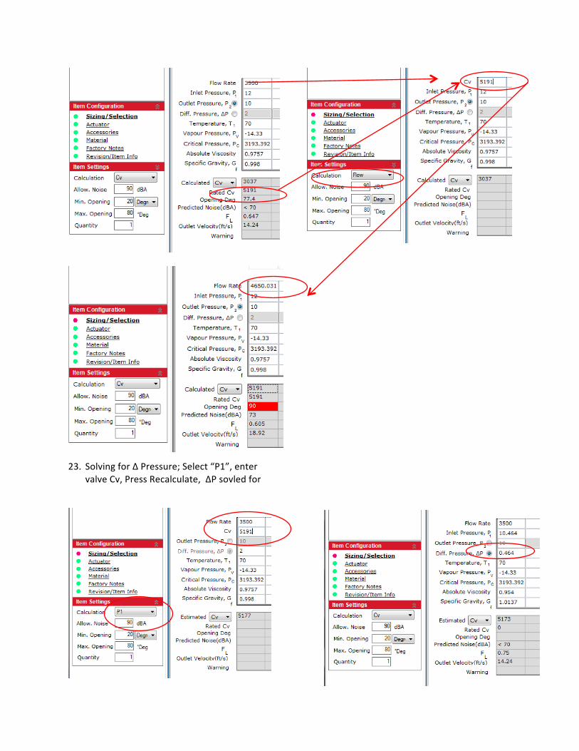
23. Solving for Δ Pressure; Select “P1”, enter valve Cv, Press Recalculate, ΔP sovled for
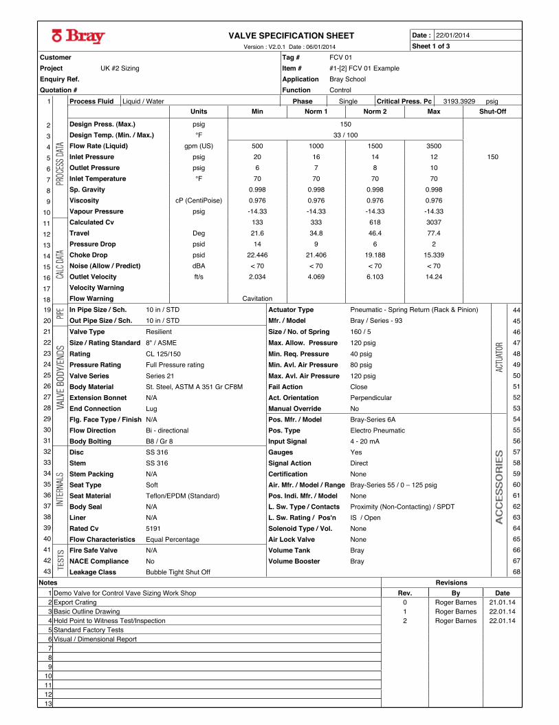
VALVE SPECIFICATION SHEET
1314
1112
1718
1516
10
45
23
89
67
Flow Rate (Liquid) gpm (US) 500 1000 1500 3500Inlet Pressure psig 20 16 14 12 150
Inlet Temperature °F 70 70 70 70Outlet Pressure psig 6 7 8 10
Design Press. (Max.) psig 150Design Temp. (Min. / Max.) °F 33 / 100
Choke Drop psid 22.446 21.406 19.188 15.339Pressure Drop psid 14 9 6 2
Noise (Allow / Predict) dBA < 70 < 70 < 70 < 70
Velocity WarningOutlet Velocity ft/s 2.034 4.069 6.103 14.24
Travel Deg 21.6 34.8 46.4 77.4
Sp. Gravity 0.998 0.998 0.998 0.998Viscosity cP (CentiPoise) 0.976 0.976 0.976 0.976
Flow Warning Cavitation
Calculated Cv 133 333 618 3037Vapour Pressure psig -14.33 -14.33 -14.33 -14.33
Units Min Norm 1 Norm 2 Max Shut-OffProcess Fluid Liquid / Water Phase Single psigCritical Press. Pc 3193.3929
Sheet 1 of 3
353637
323334
414243
383940
31
222324
192021
282930
252627
1
Date :
Project UK #2 Sizing Item # #1-[2] FCV 01 ExampleEnquiry Ref. Application Bray SchoolQuotation # Function Control
Customer Tag # FCV 01
Size / Rating Standard 8" / ASME Max. Allow. Pressure 120 psigRating CL 125/150 Min. Req. Pressure 40 psigPressure Rating Full Pressure rating Min. Avl. Air Pressure 80 psig
In Pipe Size / Sch. 10 in / STD Actuator Type Pneumatic - Spring Return (Rack & Pinion)Out Pipe Size / Sch. 10 in / STD Mfr. / Model Bray / Series - 93Valve Type Resilient Size / No. of Spring 160 / 5
Body Seal N/A L. Sw. Type / Contacts Proximity (Non-Contacting) / SPDTLiner N/A L. Sw. Rating / Pos'n IS / Open
Seat Type Soft Air. Mfr. / Model / Range Bray-Series 55 / 0 – 125 psigSeat Material Teflon/EPDM (Standard) Pos. Indi. Mfr. / Model None
Rated Cv 5191 Solenoid Type / Vol. None
NACE Compliance No Volume Booster BrayLeakage Class Bubble Tight Shut Off
Flow Characteristics Equal Percentage Air Lock Valve NoneFire Safe Valve N/A Volume Tank Bray
Stem Packing N/A Certification None
Extension Bonnet N/A Act. Orientation PerpendicularEnd Connection Lug Manual Override No
Valve Series Series 21 Max. Avl. Air Pressure 120 psigBody Material St. Steel, ASTM A 351 Gr CF8M Fail Action Close
Flg. Face Type / Finish N/A Pos. Mfr. / Model Bray-Series 6A
Disc SS 316 Gauges YesStem SS 316 Signal Action Direct
Flow Direction Bi - directional Pos. Type Electro PneumaticBody Bolting B8 / Gr 8 Input Signal 4 - 20 mA
606162
575859
666768
636465
56
474849
444546
535455
505152
22/01/2014Version : V2.0.1 Date : 06/01/2014
987
10
131211
2 Export Crating 0 Roger Barnes 21.01.141 Demo Valve for Control Vave Sizing Work Shop Rev. By Date
Notes Revisions
3 Basic Outline Drawing 1 Roger Barnes 22.01.14
6 Visual / Dimensional Report5 Standard Factory Tests4 Hold Point to Witness Test/Inspection 2 Roger Barnes 22.01.14

VALVE SIZING CALCULATION SHEET
Enquiry Ref. Application Bray SchoolQuotation # Function Control
Customer Tag # FCV 01Project UK #2 Sizing Item # #1-[2] FCV 01 Example
Downstream Pipe Size (in) 10 10 10 10Downstream Pipe Schedule STD STD STD STDValve SPL (dBA) < 70 < 70 < 70 < 70
Noise CalculationValve Type Butterfly Butterfly Butterfly Butterfly
Valve Velocity (ft/s) 3.191 6.383 9.574 22.34Outlet Velocity (ft/s) 2.034 4.069 6.103 14.24
VelocityInlet Velocity (ft/s) 2.034 4.069 6.103 14.24
Sizing Coefficient, Cv 133 333 618 3037Pressure Drop (psid) 14 9 6 2
SERVICE AND SIZING Min Norm 1 Norm 2 Max
dP Choked (psid) 22.4459 21.4058 19.1881 15.3389
Cavitation Index, Kc 0.408 0.297 0.212 0.076
Specific Gravity 0.998 0.998 0.998 0.998Vapour Pressure (psig) -14.33 -14.33 -14.33 -14.33
Pressure Recovery Factor, FL 0.808 0.837 0.815 0.647Temperature (°F) 70 70 70 70
Inlet Pressure (psig) 20 16 14 12Process Fluid Name Water
Liquid Flow (gpm (US)) 500 1000 1500 3500Outlet Pressure (psig) 6 7 8 10
Valve Diameter, d (in) 8" 8" 8" 8"
Outlet Pipe Diameter, D2 (in) 10.75 10.75 10.75 10.75Inlet Pipe Diameter , D1 (in) 10.75 10.75 10.75 10.75
Combined Recovery Factor, FLP 0.808 0.837 0.815 0.647Valve Style Modifier Factor, Fd 0.356 0.414 0.466 0.542
Critical Pressure Ratio Factor, Ff 0.957 0.957 0.957 0.957Piping Correction Factor, Fp 0.999 0.997 0.989 0.81
Item Description Series 21, 8", CL 125/150, Lug
Cv 11.7 87.4 202.6 353.8 570.5 887.2 1383.4 2228.4 3580.9 5191Travel Deg 9 18 27 36 45 54 63 72 81 90
Rated Cv: 5191
Flow Char: Equal Percentage
Valve Series : Series 21
Valve Size: 8"
Sheet 2 of 3Version : V2.0.1 Date : 06/01/2014
C - (46.4,618)
D - (77.4,3037)
Degree Opening, Calculated CvA - (21.6,133)
B - (34.8,333)
Date : 22/01/2014

ACTUATOR SIZING SHEET
Pneumatic End Torque (lbs-in) 1825 lbs-in
Manual Override NoActuator Model & Size Series - 93 & 160
Fail Safe Condition Fail Close
Max. Available Supply Pressure (psig) 120Actuator Type Pneumatic - Spring Return (Rack & Pinion)
Pneumatic Start Torque (lbs-in) 3502 lbs-in
Valve Model Series 21
Spring End Torque (lbs-in) 2240 lbs-in
No of Spring 5Spring Start Torque (lbs-in) 3917 lbs-in
Maximum Inlet Pressure (psig) 20Maximum Pressure Drop (psid) 14
Temperature (°F) 100
Valve Size (in) 8Media Water
Shut off Pressure (psig) 150
Torque with Safety factor 2190Min. Available Air Supply Pressure (psig) 80
Safety Factor 1.2
MAST (lbs-in) N/ABasic Torque (lbs-in) 1825
Sheet 3 of 3Version : V2.0.1 Date : 06/01/2014
2240 lbs-in
3917 lbs-in
1825 lbs-in
3502 lbs-in
Date : 22/01/2014
ACTUATOR SIZING
Item Description Series 21, 8", CL 125/150, Lug, Pneumatic - Spring Return (Rack & Pinion), Series - 93
Enquiry Ref. Application Bray SchoolQuotation # Function Control
Customer Tag # FCV 01Project UK #2 Sizing Item # #1-[2] FCV 01 Example

Notes:
R
CONTROLSWorkshop Notes1-22-2014