modul_b01 · web view3.1.1 example for a programming error in the function 5, the memory bit word...
TRANSCRIPT
Automation– and Drive Technology- SCE
Training document for the company-wideautomation solution
Totally Integrated Automation (T I A)
MODULE B1Error diagnostics / error handling
T I A Training document Page 1 of 18 Module B1Last revision: 02/2002 Error diagnostics / Error handling
Automation– and Drive Technology- SCE
This document was provided by Siemens A&D SCE (automation and drive technology, Siemens A&D Cooperates with Education) for training purposes. Siemens does not make any type of guarantee regarding its contents.
The passing on or duplication of this document, including the use and report of its contents, is only permitted within public and training facilities.
Exceptions require written permission by Siemens A&D SCE (Mr. Knust: E-Mail: [email protected]). Offences are subject to possible payment for damages caused. All rights are reserved for translation and any case of patenting or GM entry.
We thank the company Michael Dziallas Engineering and the instructors of vocational schools as well as further persons for the support with the production of the document.
T I A Training document Page 2 of 18 Module B1Last revision: 02/2002 Error diagnostics / Error handling

Automation– and Drive Technology- SCE
PAGE:
1. Forward............................................................................................................ 4
2. Diagnostics...................................................................................................... 62.1 Hardware diagnostics......................................................................................... 62.2 Diagnostic messages......................................................................................... 10
3. Error types....................................................................................................... 133.1 Synchronous error............................................................................................................ 133.2 Asynchronous error............................................................................................ 18
Information
Programming
Notes
T I A Training document Page 3 of 18 Module B1Last revision: 02/2002 Error diagnostics / Error handling
Forward Diagnostics Error types
Automation– and Drive Technology- SCE
1. FORWARD
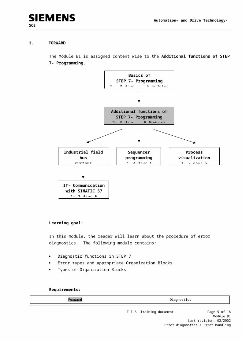
The Module B1 is assigned content wise to the Additional functions of STEP 7- Programming.
Learning goal:
In this module, the reader will learn about the procedure of error diagnostics. The following module contains:
Diagnostic functions in STEP 7 Error types and appropriate Organization Blocks Types of Organization Blocks
Requirements:
For the successful use of this module, the following knowledge is assumed:
Knowledge in the use of Windows 95/98/2000/ME/NT4.0 Basics of PLC- Programming with STEP 7 (e.g. Module A3 - ‘Startup’
PLC programming with STEP 7) Debug- and Online- Functions in STEP 7 (e.g. Module A7 - Debug- and Online- Functions)
T I A Training document Page 4 of 18 Module B1Last revision: 02/2002 Error diagnostics / Error handling
Industrial field bussystems
2- 3 days D modules
Processvisualization
2- 3 days F modules
Sequencerprogramming
2- 3 days C modules C
IT- Communicationwith SIMATIC S7
1- 2 days E modules
Basics ofSTEP 7- Programming2 - 3 days A modules
Additional functions ofSTEP 7- Programming2- 3 days B Modules
Forward Diagnostics Error types
Automation– and Drive Technology- SCE
Required hardware and software
1 PC, Operating system Windows 95/98/2000/ME/NT4.0 with- Minimal: 133MHz and 64MB RAM, approx. 65 MB free hard disk space- Optimal: 500MHz and 128MB RAM, approx. 65 MB free hard disk space
2 Software STEP 7 V 5.x3 MPI- Interface for the PC (e.g. PC- Adapter)4 PLC SIMATIC S7-300
Example configuration:- Power supply: PS 307 2A- CPU: CPU 314- Digital inputs: DI 16x DC24V- Digital outputs: DO 16x DC24V / 0.5 A
T I A Training document Page 5 of 18 Module B1Last revision: 02/2002 Error diagnostics / Error handling
1 PC2 STEP 7
4 SIMATIC S7-300
3 PC Adapter
Forward Diagnostics Error types
Automation– and Drive Technology- SCE
2 DIAGNOSTICS
You can test the following diagnostic functions presented e.g. with the STEP 7 project ‘Startup‘ from Module A3 – ‘Startup‘ PLC- Programming with STEP 7.
2.1. THE HARDWARE DIAGNOSTICS
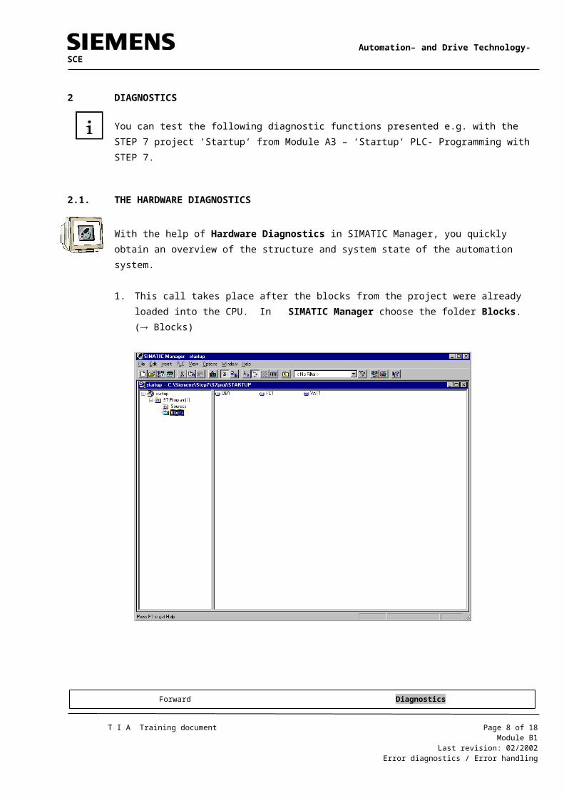
With the help of Hardware Diagnostics in SIMATIC Manager, you quickly obtain an overview of the structure and system state of the automation system.
1. This call takes place after the blocks from the project were already loaded into the CPU. In SIMATIC Manager choose the folder Blocks. ( Blocks)
T I A Training document Page 6 of 18 Module B1Last revision: 02/2002 Error diagnostics / Error handling

Forward Diagnostics Error types
Automation– and Drive Technology- SCE
2. Now the application can be called over the menu PLC , Hardware Diagnostics ( PLC Hardware Diagnostics).
3. After the call of hardware diagnostics, a Quick View appears. The quick view shows the CPU and distributed modules. The picture here shows the module information of the CPU (RUN) and the error module SM- digital.Over the command button Module Information, you reach the dialog Module Information of the module that is highlighted in blue. It appears for the digital module e.g. as the following. ( Module Information)
T I A Training document Page 7 of 18 Module B1Last revision: 02/2002 Error diagnostics / Error handling
Forward Diagnostics Error types
Automation– and Drive Technology- SCE
4. The index card General shows the operation mode and the status of the digital module. The order number, rack- and slot number as well as the address of the module are shown in the middle area of the window.In the area Status, the module announces the emerged error. In this case there exists a Preset/Actual mismatch of the module. You can find help for an error occurrence under the command button Help. The operation mode is then closed with the button Close ( Close).
Note: Repair this error through an exchange of the module in the hardware configuration and download the new configuration into the CPU.
T I A Training document Page 8 of 18 Module B1Last revision: 02/2002 Error diagnostics / Error handling

Forward Diagnostics Error types
Automation– and Drive Technology- SCE
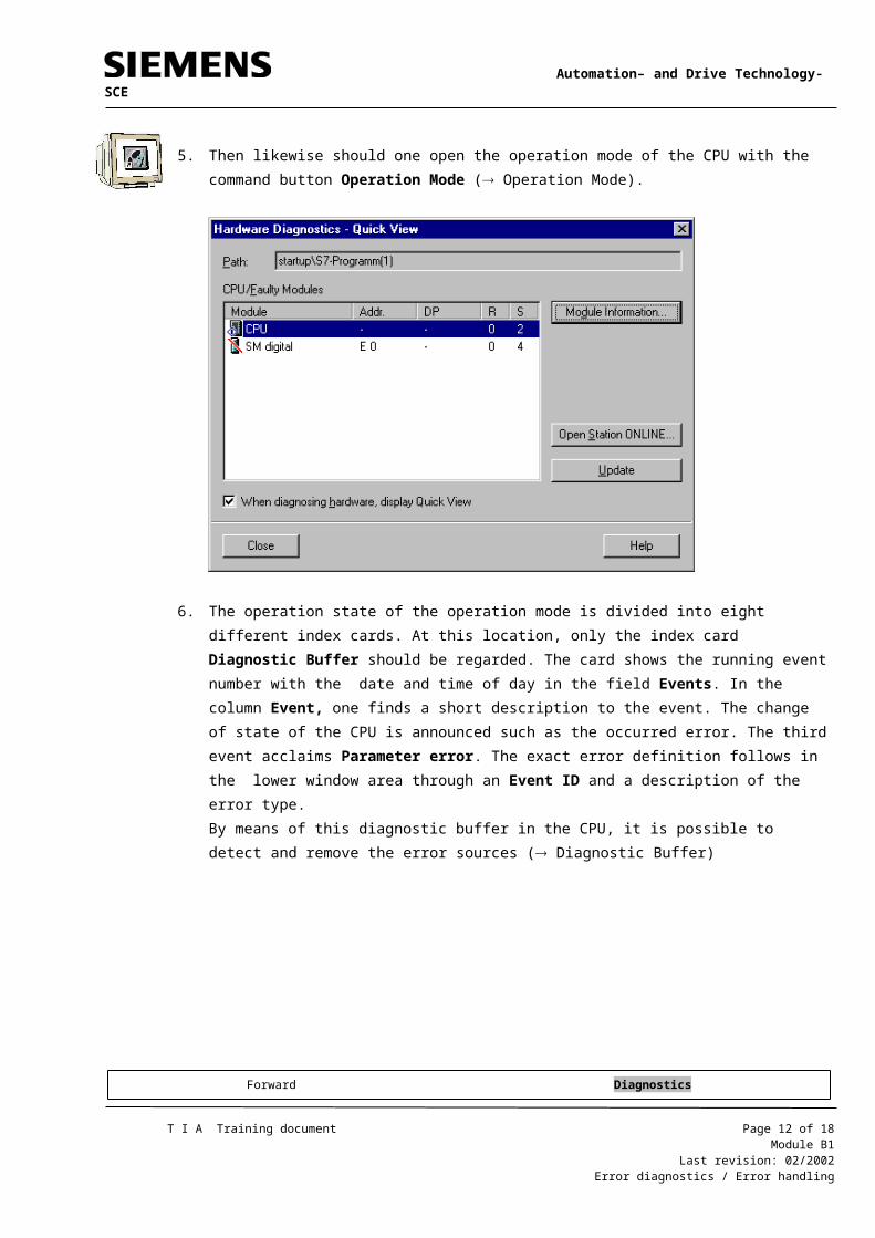
5. Then likewise should one open the operation mode of the CPU with the command button Operation Mode ( Operation Mode).
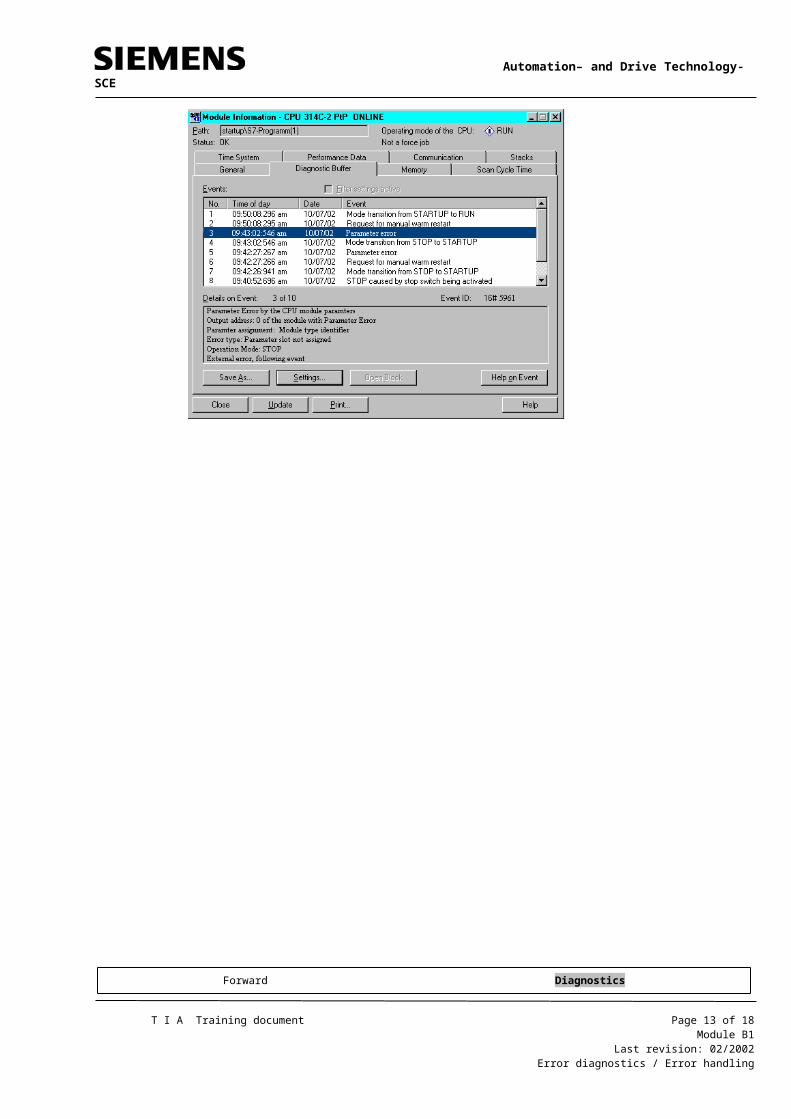
6. The operation state of the operation mode is divided into eight different index cards. At this location, only the index card Diagnostic Buffer should be regarded. The card shows the running event number with the date and time of day in the field Events. In the column Event, one finds a short description to the event. The change of state of the CPU is announced such as the occurred error. The third event acclaims Parameter error. The exact error definition follows in the lower window area through an Event ID and a description of the error type.By means of this diagnostic buffer in the CPU, it is possible to detect and remove the error sources ( Diagnostic Buffer)
T I A Training document Page 9 of 18 Module B1Last revision: 02/2002 Error diagnostics / Error handling

Forward Diagnostics Error types
Automation– and Drive Technology- SCE
2.2 DIAGNOSTIC MESSAGES
With the help of the diagnostic messages, there is a possibility to directly give out error messages by sporadic errors in the equipment. The messages let themselves be displayed on a program device or on a Modify-and Monitor device e.g. an operator or touch panel. As soon as the CPU goes through an error in Stop, a message window in the PG or OP appears.
In order to display the diagnostic messages, proceed as follows:
1. Change into SIMATIC Manager and choose the folder S7 Program(1). ( S7-Program(1) )
T I A Training document Page 10 of 18 Module B1Last revision: 02/2002 Error diagnostics / Error handling

Forward Diagnostics Error types
Automation– and Drive Technology- SCE
2. Open CPU Messages in the menu PLC ( PLC CPU Messages)
3. Then all announced CPUs and S7-Programs will be displayed. Activate the control box W and A. ( W A )
Meaning of the abbreviation W:
Click on this field, in order to activate the message from system diagnostics, respectively user diagnostic messages. A further click deactivates the message.
Meaning of the abbreviation A:
Click on this field, in order to activate the message from operation and alarm messages (ALARM_S/SQ). A further click deactivates the messages. The application ‘CPU Messages’ checks if the respected module supports any ALARM_S, respectively the ALARM_SQ. When this is not the case, a message will be given out..
Note: After each memory reset, the message display must be again activated!
T I A Training document Page 11 of 18 Module B1Last revision: 02/2002 Error diagnostics / Error handling
Forward Diagnostics Error types
Automation– and Drive Technology- SCE
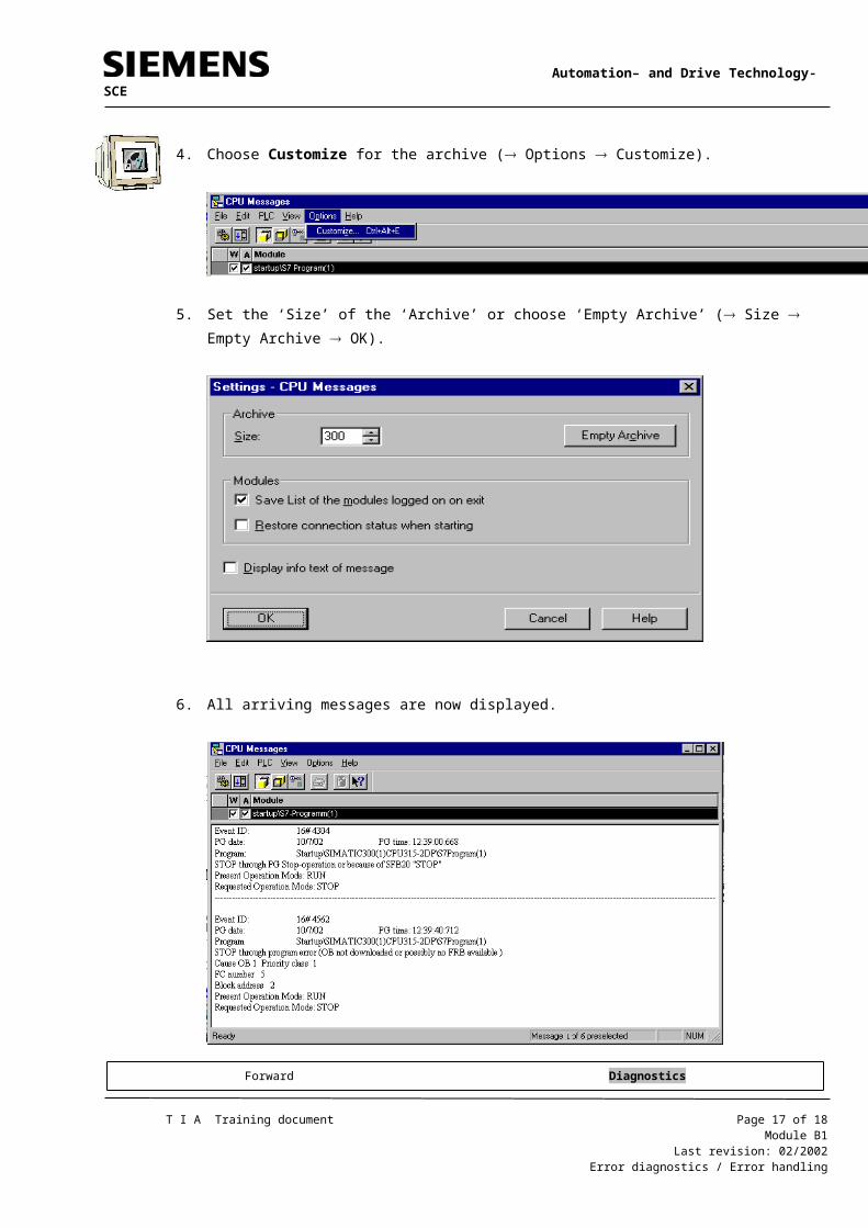
4. Choose Customize for the archive ( Options Customize).
5. Set the ‘Size’ of the ‘Archive’ or choose ‘Empty Archive’ ( Size Empty Archive OK).
6. All arriving messages are now displayed.
T I A Training document Page 12 of 18 Module B1Last revision: 02/2002 Error diagnostics / Error handling
Forward Diagnostics Error types
Automation– and Drive Technology- SCE
3 ERROR TYPES
There are error organization blocks in the SIMATIC S7-300 CPUs that are called when an error appears. Then this block is not available in the CPU, so it goes into STOPThis call will also be displayed in the diagnostic buffer of the CPU:The error is divided into two error categories:
Synchronous error
A synchronous error is generated from the operating system of the CPU when an error appears in immediate relation with the program processing. Synchronous errors are divided into programming errors and access errors. If a synchronous error appears, the operating system calls the appropriate error organization block.
Asynchronous error
Asynchronous errors are errors that can appear independent from program processing. If a asynchronous error appears, the operating system calls an error organization block.
3.1 SYNCHRONOUS ERRORS
Synchronous errors are directly determined by the processing of a command. For example, if a function call FC10 is programmed and this block is not available, then a synchronous error appears and the automation system goes into the stop mode and the red SF LED (system error) lights.
An error OB is an organization block that decides the behavior of the CPU in an error instance. By a programming error, the organization block OB121 is called and by an access error, the organization block OB122 is called. If no organization block is available in the CPU, the stop mode is reached in the error instance.
T I A Training document Page 13 of 18 Module B1Last revision: 02/2002 Error diagnostics / Error handling

Forward Diagnostics Error types
Automation– and Drive Technology- SCE
3.1.1 EXAMPLE FOR A PROGRAMMING ERROR
In the function 5, the memory bit word 20, is saved in the Data Block 10, starting from word 0. The Data Block 10 is not available in the CPU. Since no error OB is programmed, the CPU will skip the call of the FC5 in stop mode.
Exercise to this programming error:
1. Program the error in FBD in the FC5
2. Program the block call in STL in OB1.
Call FC 5
3. Download the blocks in the CPU
T I A Training document Page 14 of 18 Module B1Last revision: 02/2002 Error diagnostics / Error handling

Forward Diagnostics Error types
Automation– and Drive Technology- SCE
4. Read out of the diagnostic bufferThe diagnostic buffer shows by event number 1 under the column Event the message Stop through program error (OB not downloaded or ...).The event number 2 reports Data block not downloaded.In the window Details on event, the cause of the message, OB1 and FC5 can be read in this instance. The announcement is made in the window by one mouse click on the event. The command button Open Block opens the block online. The cursor jumps to the area where the error appeared.
5. The command button Help on Event gives tips to debugging.
Note: The error can be removed through the programming of an error OB121 or through the downloading of Data Block 10. The error OB121 does not remove thereason for the error, it only averts the stop mode of the CPU.
T I A Training document Page 15 of 18 Module B1Last revision: 02/2002 Error diagnostics / Error handling

Forward Diagnostics Error types
Automation– and Drive Technology- SCE
3.1.2 PROGRAMMING OF THE ERROR OB 121
1. The organization block is inserted in the block container over the menu S7 Block, Organization Block. (Insert S7-Block Organization Block)
2. In the dialog box Properties Organization Block give the block the name ‘OB 121’ and the created in language FBD(OB121 FBD OK).
T I A Training document Page 16 of 18 Module B1Last revision: 02/2002 Error diagnostics / Error handling
Forward Diagnostics Error types
Automation– and Drive Technology- SCE
3. When you download the OB 121 into the automation system and carry out a new start, the CPU will no longer be ignored in the stop mode. The system error is displayed over the SF LED and in the CPU and in the Diagnostic Buffer, a new error is displayed .
The error message says Length of area error by writing, the cause is a Global Data Block and Data block not downloaded, the cause is the DB10.
Repairing the program errors:
1. Apply the Data Block 102. Transfer the data block3. Carry out a new start4. Control the result
Result:
The SF-LED on the CPU goes out, the error is removed.
T I A Training document Page 17 of 18 Module B1Last revision: 02/2002 Error diagnostics / Error handling

Forward Diagnostics Error types
Automation– and Drive Technology- SCE
3.1.3 ACCESS ERROR
An access error is activated through direct access onto a defective or unavailable module.
The operating system call the OB 122 by an access error. If it is not available, the CPU goes into stop mode.
3.2 ASYNCHRONOUS ERRORS
Asynchronous errors assign themselves to no particular program actuator. This means that they appear asynchronous to the program processing.
Error type Example Error OB
Time error Exceeding of the max cycle time OB 80
Power supply error Failure of the buffer battery OB 81
Diagnostic interrupt Wire break at the input of asupporting diagnostic module
OB 82
Insert/Remove Module interrupt
Insertion/Removal of a module OB 83
CPU- Hardware fault Error by the interface to the MPI-Network, to the internal communications bus (C-Bus) or to the interface for the distributed I/O
OB 84
Priority class error Start request for a non downloaded OB, module defect
OB 85
Rack failure(only S7-400)
Failure of the module mounting by the S7-400
OB 86
Communication error False cable recognition OB 87
T I A Training document Page 18 of 18 Module B1Last revision: 02/2002 Error diagnostics / Error handling