module 11. modeling and inspection - cal poly …hturner/ce420/module11.pdf · module 11. modeling...
TRANSCRIPT

154
MODULE 11.
MODELING AND INSPECTION
Learning Outcomes:
Students should be able to perform cloud-based modeling, to compare as-built features
with models and to create models with or without the point cloud.
Lecture Contents:
Although point clouds may look like objects when the scan resolution is high, they are
not objects (geometries). The Modeling module in RWS provides many tools that allow the
users to create and modify objects with or without point clouds. The features covered in this
module include cloud-based modeler, geometry creator and geometry modifier tools. In
addition, an inspection tool in the OfficeSurvey module will be used to compare the as-built
point cloud with the design model.
11.1 Cloud-Based Modeling and the Geometry Modifier Tool
RWS can be used to fit point clouds into geometrical shapes. Users can reverse-engineer
a feature from point clouds. Nine types of geometrical entities can be extracted from the point
clouds. Here are steps to extract a cylinder from the point cloud.
1. Select Modeling in the Module Dropdown List.

155
2. Select a point cloud and then choose Cloud based Modeler Tool in the Modeling menu.
3. The Cloud Based Modeler dialog box appears and the Segmentation Toolbar is
automatically opened.
156
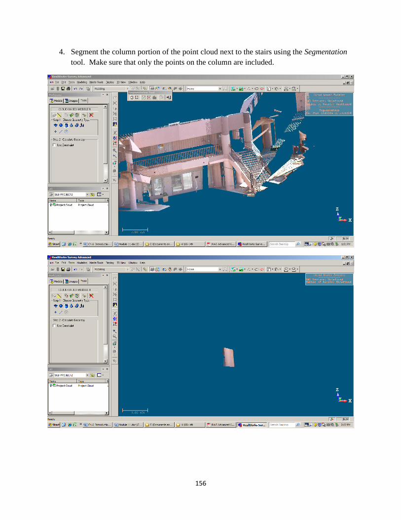
4. Segment the column portion of the point cloud next to the stairs using the Segmentation
tool. Make sure that only the points on the column are included.
157
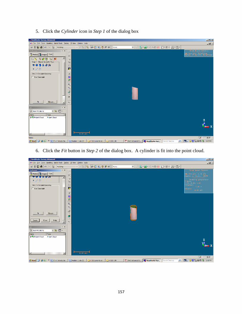
5. Click the Cylinder icon in Step 1 of the dialog box
6. Click the Fit button in Step 2 of the dialog box. A cylinder is fit into the point cloud.

158
7. Click the Create button to create the cylinder.
8. To modify the geometry, select the Geometry Modifier Tool in the Modeling menu.
159
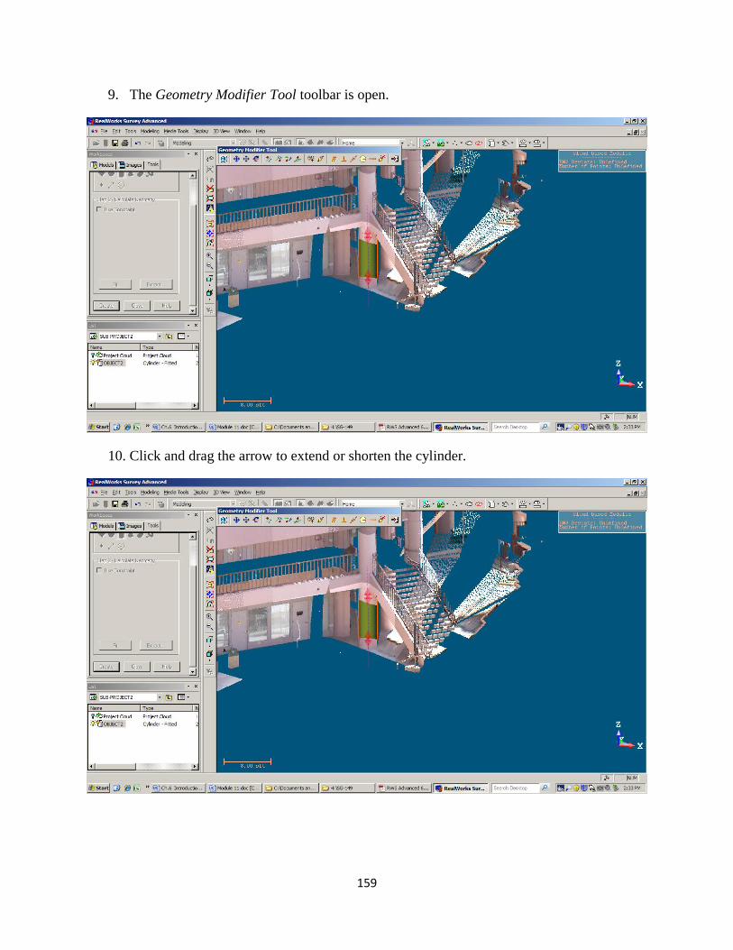
9. The Geometry Modifier Tool toolbar is open.
10. Click and drag the arrow to extend or shorten the cylinder.

160
11. The cylinder is modified. Close the Geometry Modifier toolbar and the Cloud Based
Modeler dialog box. Click Yes if asked to create the object.
12. Turn off the point cloud to see the newly created cylinder.

161
11.2 Geometry Creator Tool
The Geometry Creator Tool in RWS can be used to create a variety of geometrical shapes.
Unlike the Cloud-Based Modeler Tool, this option does not require the selection of a point cloud
to get activated. Users can, however, create geometries using images and point clouds as
reference.
1. On the Menu bar, click 3D View, and select Station-Based under Mode submenu.

162
2. The station-based view is shown with the image matching the cloud. Select Modeling in
the module drop-down list.
3. Pan and zoom to the desired view.
163
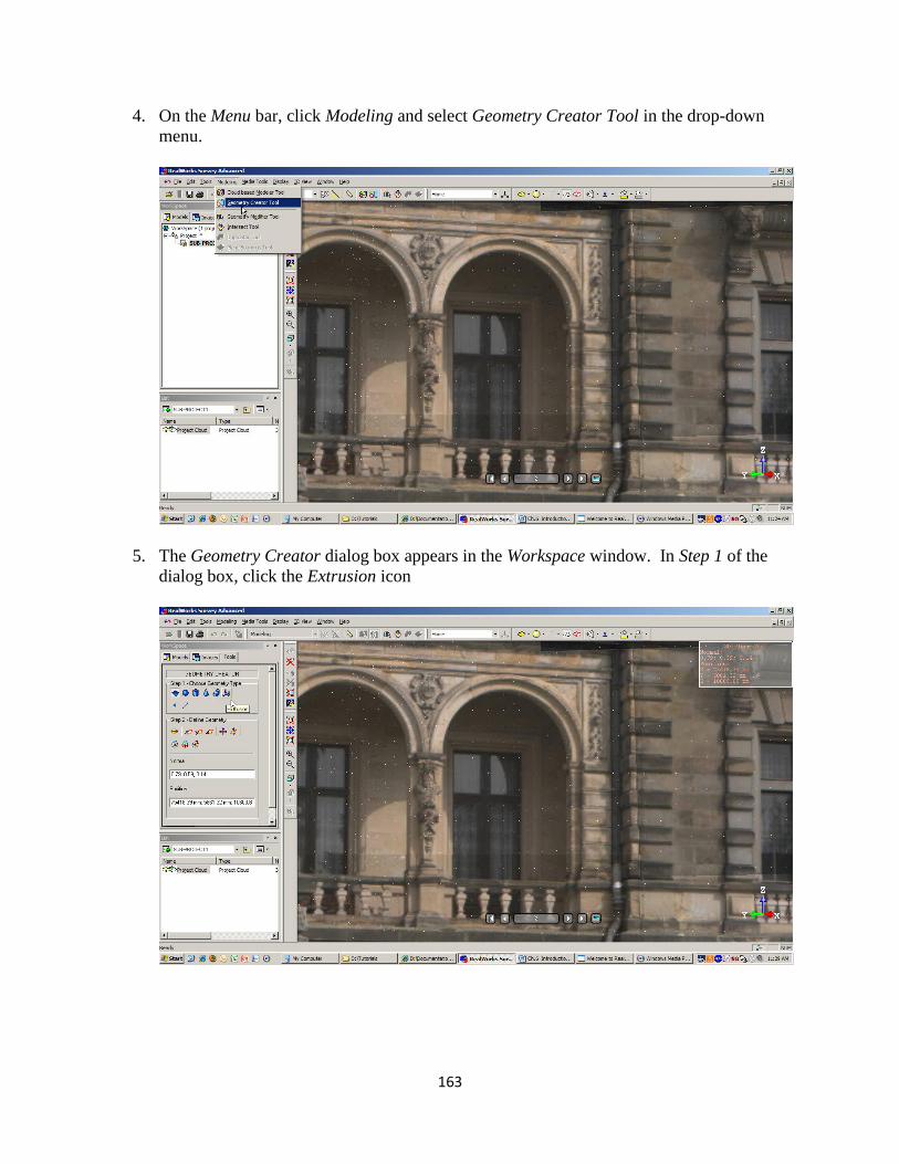
4. On the Menu bar, click Modeling and select Geometry Creator Tool in the drop-down
menu.
5. The Geometry Creator dialog box appears in the Workspace window. In Step 1 of the
dialog box, click the Extrusion icon

164
6. The Drawing Tool toolbar appears. Click the Launch 3D Plane Tool icon.
7. The 3D Plane Tool toolbar appear. Click the Define vertical plane by picking two screen
points and one 3D point icon.
165
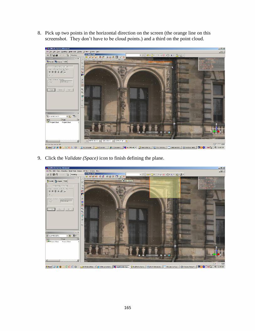
8. Pick up two points in the horizontal direction on the screen (the orange line on this
screenshot. They don’t have to be cloud points.) and a third on the point cloud.
9. Click the Validate (Space) icon to finish defining the plane.

166
10. Select the Change mode to line (this is the default choice) icon on the Drawing Tool
toolbar.
11. Draw the first vertical line around the balcony door.

167
12. Select Change mode to arc in the Drawing Tool toolbar to draw an arc connected to the
line.
13. Change the drawing mode back to line by selecting Change mode to line in the toolbar.
168
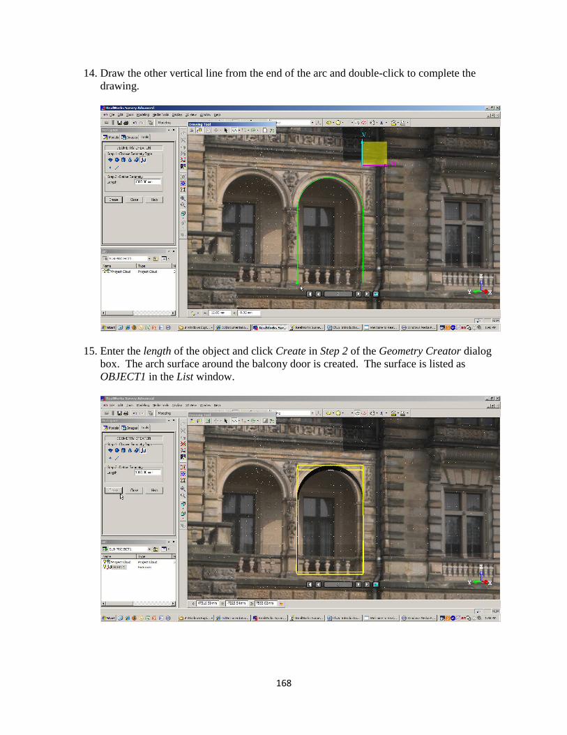
14. Draw the other vertical line from the end of the arc and double-click to complete the
drawing.
15. Enter the length of the object and click Create in Step 2 of the Geometry Creator dialog
box. The arch surface around the balcony door is created. The surface is listed as
OBJECT1 in the List window.

169
16. To modify the arch surface, click Modeling on the Menu bar and then select Geometry
Modifier Tool.
17. The Geometry Modifier Tool toolbar appears. Select an option to perform the
modification (the screenshot shows the rotate option. Drag the ball to rotate). Close the
Geometry Modifier Tool toolbar when done.

170
18. Close the Geometry Creator dialog box. Click the Station Image Control icon to hide the
image.
19. Only the arch surface and the point cloud are left in the view.

171
11.3 Surface to Model Inspection Tool
This is an option under the OfficeSurvey module, which can be used to compare an as-
built structure with a CAD model and to create inspection maps. We are going to inspect an as-
built column with a 3D model created with AutoCAD in this example.
1. Open a file with point clouds (.ppf, .rwp, etc.)

172
2. Open a CAD file (.dwg or .dxf from AutoCAD) by selecting Open in the File menu.
3. The Open file dialog box appears. In the File Type dropdown list, select AutoCAD Files
(*.dxf, *dwg).
173
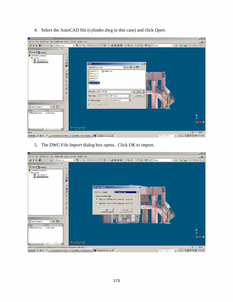
4. Select the AutoCAD file (cylinder.dwg in this case) and click Open.
5. The DWG File Import dialog box opens. Click OK to import.

174
6. The imported DWG file folder appears in the list window.
7. Turn off the point cloud to see the imported model (a cylindrical column). Click on the
model to select it.

175
8. Turn on the point cloud and Ctrl-Click the point cloud to select it too. Now, both the
model and the point cloud are selected.
9. Select Surface to Model Inspection Tool in the OfficeSurvey menu.

176
10. The Surface to Model Inspection dialog box is open.
11. We are going to inspect a portion of the as-built column by comparing it with the design
model. Use the Segmentation tool in the dialog box to select the bottom half of the
column point cloud.

177
12. Enter a resolution value in Step 1 of the dialog box and click Preview in Step 2 to see the
inspection map. The 3D View window is split into two, the top one shows a 2D map with
a color bar representing the difference between the as-built surface and the model and the
bottom window shows the inspection map in 3D with the point cloud.

178
13. Click the Inspection Map Analyzer button in Step 3 of Surface to Model Inspection. The
Inspection Map Analyzer dialog box is open and the bottom half of the 3D View window
becomes a Section Viewer with a Section Difference Plot. To view a different section of
the map, move the cursor to grips (the little triangles at the end of the dotted line) and
drag it up and down (or left and right for the vertical dotted line).

179
14. To print the Inspection Map or Section Difference Plot, right-click in the window and
select Print.

180
15. Click Create All to create the sections and Close to exit the Inspection Map Analyzer
dialog box.
16. Click Create in the Surface to Model Inspection dialog box to create the inspection map.
181
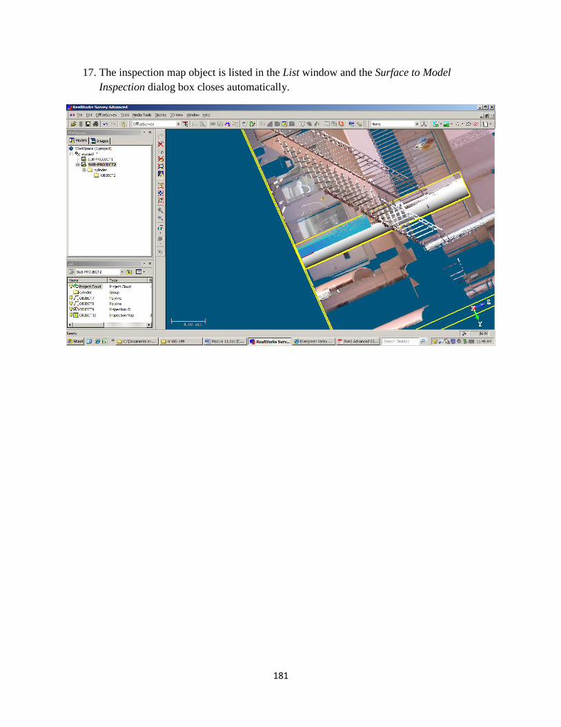
17. The inspection map object is listed in the List window and the Surface to Model
Inspection dialog box closes automatically.

182
Questions:
1. Explain the differences between point clouds and geometries (models).
2. Discuss the steps to fit a point cloud into a geometrical shape.
3. Section 11.2, what is the purpose of going into Station-Based mode before using
the Geometry Creator Tool to create an arch?
4. Does a point cloud have to be selected before using the Geometry Creator Tool?
Discuss the procedure of creating and modifying a geometrical shape in RWS.
5. What is inspection in RWS? An inspection Map? A Section Difference Plot?
Discuss the procedures to create, edit and print an inspection map.