module 11 wired and wireless physical layers
TRANSCRIPT

Computer Networks and ITCP/IP Protocols 1
Prof. Bhushan Trivedi Module 11
Module 11 Wired and wireless physical layers Introduction In this module, we will look at wired and wireless physical layer components. We will begin
with different types of cables used in wired networks like UTP and Fiber Optics cable. We
will also compare them on different grounds. We will look at two common problems occur
at wireless physical layer and conclude by introducing some components of the wireless
physical layer.
The UTP cable The Unshielded Twisted Pair (UTP) copper cables are the de-facto standard for Ethernet
cabling system. UTP cables are twisted in helical fashion like a strand of a DNA. Twisted are
introduced for a special purpose. UTP cables are also used in telephone lines. Unlike older
landline telephones, there are no incidents of crosstalk in current landline phones due to
UTP cables twisted design. In networking, the twists help avoid data leakage. Apart from
this, there are other benefits of the UTP cables. Here is a list.
1. They are quite inexpensive, a few rupees a meter in India.
2. It is possible to bend the cable without much of a trouble, thus laying out cable
won’t be a problem.
3. UTP is in use for a very long period now, engineers to install it and maintain it are
easily available
4. The attenuation (losing power over a distance) is less compared to other types of
copper cables used in past. It runs for a longer distance without amplification.
5. The technology is evolving. The UTP cables versions are named as category or Cat.
For example, Cat-3 means category 3 type of UTP cable and so on. The capacity of
the cables has increased from 25 MHz to 2000 MHz. Cat-3 cables used to provide
25MHz, cat-5 125MHz, Cat 6 can provide 250 MHz, 6A provided 500 MHz, Cat -7
provided 600 MHz, 7A 1000 MHz, cat-8 standard claims to provide 1600 MHz to
2000 MHz. Higher frequencies translate into higher bandwidth and thus these higher
end cables can send and receive much higher amount of data.
The UTP cables are pervasive in current network technology. However, they are rapidly
being replaced by fiber optic cables and soon we may find fiber optic cables everywhere.
Fiber has already spread its wings in long-haul networks and backbones. It is even replacing
the TV cable networks and become a first choice technology for Ethernet as first mile (EFM)
and carrier grade Ethernet (CGE) which are Ethernet based technologies used for long
distance transmission. EFM is used for connecting a network to an ISP and CGE is used to
connect two far away networks using a point to point link.
Computer Networks and ITCP/IP Protocols 2
Prof. Bhushan Trivedi Module 11
Before we start discussing the Fiber Optic cables, let us learn about an important principle
on which the FO cables are based on, the Total Internal Reflection Principle.
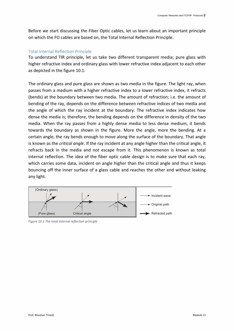
Total Internal Reflection Principle To understand TIR principle, let us take two different transparent media; pure glass with
higher refractive index and ordinary glass with lower refractive index adjacent to each other
as depicted in the figure 10.1.
The ordinary glass and pure glass are shown as two media in the figure. The light ray, when
passes from a medium with a higher refractive index to a lower refractive index, it refracts
(bends) at the boundary between two media. The amount of refraction; i.e. the amount of
bending of the ray, depends on the difference between refractive indices of two media and
the angle of which the ray incident at the boundary. The refractive index indicates how
dense the media is; therefore, the bending depends on the difference in density of the two
media. When the ray passes from a highly dense media to less dense medium, it bends
towards the boundary as shown in the figure. More the angle, more the bending. At a
certain angle, the ray bends enough to move along the surface of the boundary. That angle
is known as the critical angle. If the ray incident at any angle higher than the critical angle, it
refracts back in the media and not escape from it. This phenomenon is known as total
internal reflection. The idea of the fiber optic cable design is to make sure that each ray,
which carries some data, incident on angle higher than the critical angle and thus it keeps
bouncing off the inner surface of a glass cable and reaches the other end without leaking
any light.
Figure 10.1 The total internal reflection principle

Computer Networks and ITCP/IP Protocols 3
Prof. Bhushan Trivedi Module 11
The attenuation (loss of power) in the copper cable is due to stray electrons which provide
resistance to moving electrons. In the case of fiber optic cables, photons are being sent
which does not get affected by other photons and thus there is no resistance. Also, the light
is bouncing back without any leakage. These two properties together make fiber-optic a
choice for very long range transmission.
Once we have learned about this important principle, let us move on to learn about the FO
cable itself.
FO Cable The FO cable is made up of pure glass which is extremely transparent, one can see through
that glass to about 40-kilometer distance as it offers almost no resistance to the passing
light. The FO cables carry light pulse and the definition of ones and zeros in FO cable is
simplified to the extent that existence of a light pulse indicates 1 and absence indicate 0.
We have already seen that FO cables are not affected by Shannon's theorem and limit of
transmission rate based on temperature. That means FO cables can operate much faster
than copper cables. The bandwidth offered by FO cable, therefore, is very huge, in terms of
terabits. However, there is a limiting factor. The computers work with electrical circuits. The
FO cables use optical signals (light pulses), The electrical signals are to be converted to the
light pulses at the sender and converted back to electrical pulses at the receiver. The device
called photodiode is used at the receiver to convert a light pulse into an electric current.
When the light pulse reaches the photodiode, it illuminates it for some time and if another
light ray incident on the photodiode at the same point of time, it will not generate a
separate electrical current and thus not registered as a separate ray. That means it is
necessary to have some distance between two incident rays. That limits the current speeds
at which FO cables operates. Even with that limitations, the FO cables are able to squeeze
bandwidth in the range of 25-50 Gb for the considerable distance.
Let us try to understand two of the important characteristics of the FO cable.
Wavelength Range: - Fiber operates in the range of visible lights. There are three different
types of bands used. The first range is called 0.85 microns, the second range is 1.30 and
third is 1.55 micron. When we state a value like above, we are describing the wavelength of
the wave in the vacuum. This value indicates the middle value of the frequency range used
for transmission1. The first range of 0.85-micron has an attenuation of about 0.8
decibels/km while other two have 0.2 decibels/km. Thus the latter two ranges are capable
of driving signal much further than the first one. All three ranges are 25,000 to 30,000 GHz
wide. That means each one of them is capable of having that bandwidth. Though the first
1 This is always the case. When we state that a device is operating at frequency x, x is the middle value in the
range the device operates.

Computer Networks and ITCP/IP Protocols 4
Prof. Bhushan Trivedi Module 11
range has higher attenuation, it is preferred for shorter range as the sending and receiving
diodes can both be made from gallium arsenide, a cheaper material.
Figure 11.2 Dispersion is spreading light in all directions
Dispersion: - when we point a flashlight upwards at night, the light does not travel only
upwards but also spread in all directions. This effect is called dispersion. Dispersion limits
the placement of light pulses nearer to each other. We have seen that the multimode fiber
is capable of carrying multiple light pulses together. If we place them nearby, they merge
into each other after some distance due to dispersion. A wave traveling long enough
outstretches itself due to dispersion and collide with a neighboring wave (which is also
spreading out due to the same effect). Thus if the wave has to travel a long distance, we
have to keep other waves much apart so they do not collide due to dispersion, in a way
limiting the number of waves traveling in a wire and thus limiting the bandwidth one can
squeeze out of the FO cable.
Types of Fiber We have already mentioned the multimode fiber, which can carry multiple rays at the same
point in time. These rays travel independently, at different angles and do not merge into
each other while traveling. It is like multiple vehicles traveling on the highway. The only
difference is that the light rays travel in a zigzag way over fiber and not in a straight line
most of the times. These rays have different modes of traveling over the FO cable and hence
the name. Each of the rays, traveling in the FO cable, is sent in a way that it incident on the
boundary of the cable at an angle larger than the critical angle and thus continue like that
till the receiver receives it.
If the diameter of the cable if reduced further to a few wavelengths thick, a different
phenomenon is observed. The traveling light ray does not bounce off the surface now, it just
travels along the FO cable. The downside of this mechanism is that it only allows one way to
travel inside the fiber at the same point in time. Unlike multimode fiber, where dispersion
and other effects reduce the maximum distance to a few kilometers, this type of fiber can
drive the wave to a much longer distance. Some versions can even carry 50 Gbps data to
nearly 100 Km without needing a repeater or amplifier. This version of fiber is known as
single mode as only one ray can run through this cable at any given point of time. The single
mode fiber design requires much better precision than the multimode sibling and thus are
more expensive than them. However, for longer distances, there is no other option possible
Computer Networks and ITCP/IP Protocols 5
Prof. Bhushan Trivedi Module 11
but to use the FO single mode cable. A multimode fiber uses a diode as a sending device
while the single mode fiber uses a laser to drive the light to much longer distance.
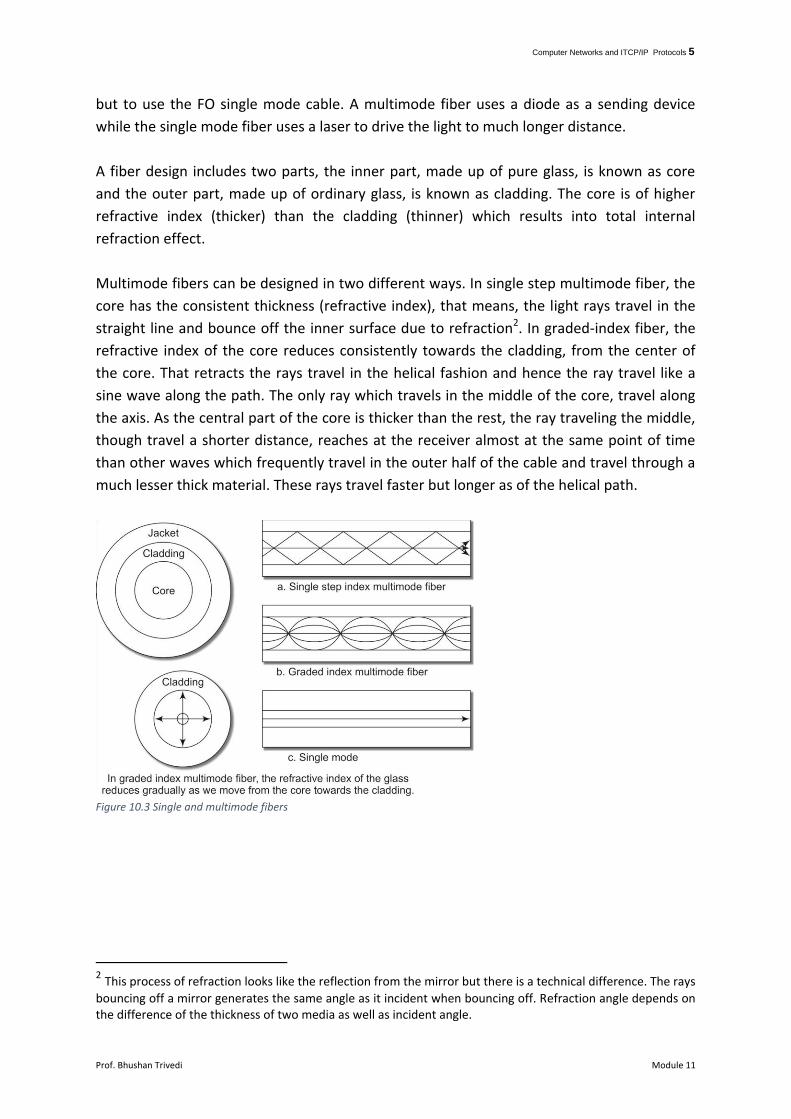
A fiber design includes two parts, the inner part, made up of pure glass, is known as core
and the outer part, made up of ordinary glass, is known as cladding. The core is of higher
refractive index (thicker) than the cladding (thinner) which results into total internal
refraction effect.
Multimode fibers can be designed in two different ways. In single step multimode fiber, the
core has the consistent thickness (refractive index), that means, the light rays travel in the
straight line and bounce off the inner surface due to refraction2. In graded-index fiber, the
refractive index of the core reduces consistently towards the cladding, from the center of
the core. That retracts the rays travel in the helical fashion and hence the ray travel like a
sine wave along the path. The only ray which travels in the middle of the core, travel along
the axis. As the central part of the core is thicker than the rest, the ray traveling the middle,
though travel a shorter distance, reaches at the receiver almost at the same point of time
than other waves which frequently travel in the outer half of the cable and travel through a
much lesser thick material. These rays travel faster but longer as of the helical path.
Figure 10.3 Single and multimode fibers
2 This process of refraction looks like the reflection from the mirror but there is a technical difference. The rays
bouncing off a mirror generates the same angle as it incident when bouncing off. Refraction angle depends on the difference of the thickness of two media as well as incident angle.

Computer Networks and ITCP/IP Protocols 6
Prof. Bhushan Trivedi Module 11
Figure 10.3 summarizes our discussion so far. In the case of single mode fiber, it clearly
shows how the ray travels in the straight line without bouncing off. The outermost layer of
the cable is called the Jacket. The jacket acts as a protective layer and shields the cladding
and the core from abrasion, crushing and moisture.
Multimode fibers are used in LAN as they favor shorter distance. Single-mode fibers are
used in the backbone networks and point to point long distance lines.
Before we conclude this session, let us see how the light pulses are generated and received
by the receiver. The sender uses LED or light emitting diode to convert electric pulses
(generated by computers as per the values zeros and ones received) into light pulses. The
light travels along the FO cable and receiver uses a photodiode to convert the light pulse
back to an electric pulse.
Figure 10.4 Generating and receiving light pulses

Computer Networks and ITCP/IP Protocols 7
Prof. Bhushan Trivedi Module 11
We have already learned that the FO cable can carry data in terms of terabytes per second
but the limitation comes from the speed of conversion of the light pulse into an electric
pulse. The speed of photodiode is crucial in determining that rate.
Sending device can even be the laser as mentioned before. The laser is more fragile and
requires expensive circuitry but its rate of conversion is much more than LED and thus
sender who uses laser can send at much higher rate than LED. However, LEDs are preferred
in LAN for a few reasons. First, for a short distance communication like LANs, LED can work
quite satisfactorily, and second, a laser can severely damage humans3 if the light is leaked.
Long distance communication does not have these issues and can use the laser. Lasers are
also sensitive to temperatures and thus sending device must be kept under controlled
temperatures, unlike LEDs.
UTP vs. FO Let us now see the difference between UTP and FO cables. So far, UTP has ruled the LAN
world and FO are used in interconnecting LANs. Slowly but surely, FO cable is picking up the
LAN space as well.
1. FO cables are not as thick as UTP. A multimode fiber is less in diameter than human
hair (almost 1/6th of the human hair). The UTP is much thicker.
2. The weight difference between them is equally huge and is about 100 times more
against UTP cable.
3. The amount of volume occupied by the UTP cable as compared to the FO cable
carrying the same amount of traffic also comes out to be in that range. According to
one report, comparing a typical UTP 5e cable (which is state of the art when this is
being written), with a typical FO cable used in practice, the volume difference comes
out to be 112.5 times. Thus an FO cable can take up 100 times less space than a UTP
5e cable. The case was for a short distance. For longer distances, the difference
increases manifold. In this case, the number of UTP 5e cables needed for comparing
with the FO cable is about 450. For a longer distance, it can be much beyond
hundred.
4. All three reasons cited above makes the FO cable suited for many places. For
example, City ducts where telephone lines are passed are designed decade before
and running short of space. Replacing them with FO cables solves the problem. High-
rise building cabling requires minute calculations about structural design that can
bear the better amount of loads. FO cables again win hands on in this case. Aircraft
and automobile industries also benefit from using lightweight and more powerful FO
cables.
3. The laser is the collection of highly concentrated rays, it is used in surgeries of cataract removal. A casual
onlooker can have a hole in his retina if he tries to see what is happening inside a breached FO cable.

Computer Networks and ITCP/IP Protocols 8
Prof. Bhushan Trivedi Module 11
5. One major difference is about the distance the cable sustains without being
amplifying the signal. Due to inherent properties we discussed before, an FO cable
can travel 50 to 60 km without amplification even at the speed of 1 Gb. Such a long
distance communication is impossible for a UTP cable, which demands amplification
(or applying repeater) at nearly 5 Km even when using much lesser data rate. While
laying cables on the seabed, where it is impossible to amplify the signals every few
kilometers, FO is the only choice.
6. The FO cables transmit photons which are immune to any interference by other
photons, unlike electrons which suffer from resistance during transmission by stray
electrons in the media. External interference also introduces problems during
transmission based on electrons. External interference generates a magnetic flux
which sometimes renders the UTP cables useless in such an environment. FO cables
do not suffer from external interference and can be used in such circumstances.
7. Another problem with copper cable is erosion. In conditions like seabed installations,
it erodes even faster. Thus, we have another reason to have FO installations on
seabed instead of UTP cables.
8. Not only the UTP cable is affected by external interference, it also affects external
entities, like other UTP wires running along. Such a situation introduces cross-talk.
The twists reduce the cross talk to a large extent but the effect is still there. Unlike
that, the FO cables do not have any effect on the external environment. An
important side effect of this characteristic is that it is easy to wiretap a UTP cable but
not an FO cable.
9. Copper is easy to splice, knot and join. Connecting Fiber cables is not that easy and
demand special tools to work with. However, that works in favor of customers who
are wary of wiretapping and eavesdropping.
10. The major advantage of FO cable is the bandwidth. It is possible to squeeze 50 Tb
speed for an FO cable for a reasonable distance like 100 meters which is about a 50
thousand times more than a UTP cable. There are many applications like online
gaming and video conferencing demand such high bandwidth. So even in the case of
a LAN, there is a demand for FO cable based installations.
Wireless Physical layer So far, we concentrated on a wired physical layer but the wireless physical layer is equally
important as many different types of wireless networks are in vogue today. The inherent
limitation of location vanishes with wireless networking. Users have many choices today,
Wi-Fi and Wi-Max are used for limited mobility and city-wide mobility solutions while ISP
based 2G,3G, and 4G solutions provide the facility to communicate even when one moves
around in an entire state (called circle in their parlance). We can now move around freely
without a fear of losing connectivity, a feat possible due to wireless physical layer that our
devices like a laptop and mobile phones provide. We will look at many complexities involved
in managing these wireless physical layers. One of the biggest differences between a wired

Computer Networks and ITCP/IP Protocols 9
Prof. Bhushan Trivedi Module 11
and wireless physical layer is that a wired physical layer, naturally, is a point to point while a
wireless physical layer inherently is a broadcast network.
The wireless physical layer, being a broadcast solution, inherits pros and cons of such
networks. For example, it does not need specific addressing and easy to eavesdrop. The
receiver can be anywhere in the vicinity and the message would reach it even if it is mobile.
The downside is that the spectrum is shared and thus wireless physical layer is always short
of bandwidth.
Before we start looking at the wireless physical layer, let us learn about two special cases,
Hidden, and Exposed stations.
Hidden and exposed stations Wired network has one distinct advantage, all nodes are connected and reachable to all
others. Unlike that, a wireless networks reachability depends on many things including the
power of the device, placement of the device, obstacles, interference from other wireless
transmissions, the mobility of the device etc. Therefore, a wireless device always
communicates in a specific range only, that means, it is possible that a wireless device may
not be reachable from another device.
When a wired node broadcasts, it reaches to all nodes while wireless node broadcasts, it
only reaches to nodes inside its range and no other nodes. The limited range has both pros
and cons. One of the advantages of the limited range is that it is possible to have multiple
transmission happening in parallel. Look at figure 10.4. Two nodes A and E are transmitting
to B and F respectively in parallel. The curve indicates the range. Thus A and E have
exclusive ranges and thus they do not interfere with each other despite transmitting
together. If either of their range is larger, the parallel communication would not have been
possible.
Figure 10.5 multiple parallel transmission.
In above case, we have two transmissions without overlapping. It is interesting to see that
even when both transmissions overlaps, there is a possibility that both transmissions can
happen in parallel if neither of the receivers is in the intersecting range.

Computer Networks and ITCP/IP Protocols 10
Prof. Bhushan Trivedi Module 11
Figure 10.6 Parallel overlapping transmission where receivers are not part of intersection, Exposed station problem
Closely observe the figure 10.5. The range of two transmission overlaps and one of the
sender belongs to the intersecting range but as long as the receivers do not receive both
signals, there is no chance to have a garbled signal and the transmission can go on. Only in
the intersecting range, the receivers get both signals and thus get a resultant garbled
signal4.
Figure 10.7, Hidden station problem
Look at figure 10.6. We have a receiver D which is in the range of two senders and it
receives the signal from both of them (B and E). The result? D cannot understand anything.
This typical nature of wireless communication results into two unique problems for wireless
networks. We will look at both, known as the exposed station problem and the hidden
station problem, in the following.
Look at figure 10.5 again. Suppose A is transmitting to B and D wants to transmit to E. If D
listens to the channel before transmission, D will find it busy. D may differ to transmit but in
an actual sense even if it transmits, there is no harm as the receiver is not in the range of
4When two signals collide, they generate a resultant signal which is a summation of both the signals. If it is
possible to decipher the summed signal back to an original set of signals, they do not result into garbage but in most cases it does. A solution called Code Division Multiple Access or CDMA uses a method when signals summed up and one can get the original component signal back from the resultant signal. Unlike that, GSM or Global system for mobile communications is a scheme where if there are multiple signals collide, they result into garbage
Computer Networks and ITCP/IP Protocols 11
Prof. Bhushan Trivedi Module 11
both senders. This is known as exposed station problem as because A is exposed to D, it
confuses it. The exactly opposite problem happens with the latter case depicted in figure
10.6. when B is transmitting to D, and E wants to send something to D, it finds no
communication as B's transmission is not reaching it. If E transmits now, it will collide with
B's transmission. Here the problem arises because B is hidden from E. This problem, thus, is
aptly named as a hidden station problem.
Solution to Hidden and Exposed stations One typical mode of Wi-Fi communication, where the problems that we have discusses so
far actually exists, the designers have found an interesting solution which we will look at in
the following.
If you are diligent enough, you could easily conclude that both of these problems are due to
a single reason, instead of sender sensing the channel in its vicinity, the receiver should
sense the channel in its vicinity. If there is any traffic near the receiver, the sender should
wait. If there is no traffic near the receiver, the sender can send even if there is a traffic
surrounding itself.
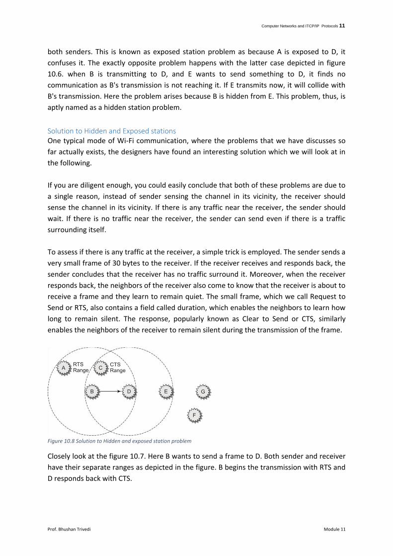
To assess if there is any traffic at the receiver, a simple trick is employed. The sender sends a
very small frame of 30 bytes to the receiver. If the receiver receives and responds back, the
sender concludes that the receiver has no traffic surround it. Moreover, when the receiver
responds back, the neighbors of the receiver also come to know that the receiver is about to
receive a frame and they learn to remain quiet. The small frame, which we call Request to
Send or RTS, also contains a field called duration, which enables the neighbors to learn how
long to remain silent. The response, popularly known as Clear to Send or CTS, similarly
enables the neighbors of the receiver to remain silent during the transmission of the frame.
Figure 10.8 Solution to Hidden and exposed station problem
Closely look at the figure 10.7. Here B wants to send a frame to D. Both sender and receiver
have their separate ranges as depicted in the figure. B begins the transmission with RTS and
D responds back with CTS.

Computer Networks and ITCP/IP Protocols 12
Prof. Bhushan Trivedi Module 11
How could this simple mechanism thwart both the problems? Let us try to understand. The
exposed station problem occurs when there is a busy surrounding at the sender's end but
free at the receiver's end. In that case, the sender who sends RTS can get the CTS back can
understand that the transmission can happen. Thus the exposed station problem is solved.
The CTS nullifies the chances of any hidden station problem. The Hidden station problem
occurs when a sender is not reachable from the station who wants to send something. In
this case, a neighbor E might be interested in sending something to D. It will not listen the
RTS but surely the CTS and thus even if cannot listen to the hidden station B, but aware of
its existence and know about the frame being transmitted. Thus it can avoid sending during
that period.
The only question remains to answer if there are two senders, who want to send one
receiver at the same point of time, what happens. In that case, the RTS from two senders
collide and the receiver does not respond back. Both senders try after a random period and
whoever succeeds will transmit. Please also understand that there is no possibility of one
sender is already sending and another sends an RTS. As the other sender has begun its
transmission with RTS and the intended recipient would have responded back with CTS, the
potential sender would have already learned about the transmission and thus would not
send.
Let us try to elaborate. If A and D both send the RTS to B, for example, B receives a garbled
RTS and does not respond. Both A and D decides a random period and send after that
period. It is highly unlikely that both of them choose the same time and thus one of them
chooses a shorter period than the other. If A has chosen a shorter period than D, A will
retransmit the RTS after that duration and upon receiving the RTS or CTS, all neighbors
including D will remain silent for the time till the frame gets over. While A is sending to B, is
there any possibility of any other potential sender sending an RTS? No. Why? All neighbors
or A would have received the RTS from A and all neighbors of B would have received the CTS
from B and thus none of them will send any frame during that period, leave along RTS. So,
there is no possibility of somebody sending RTS during that period.
Whatever smart this solution looks like, it adds a lot of overhead ironically and is not used
practically in Wi-Fi. It still proposes an interesting method to combat hidden and exposed
station problems.
Components used at wireless physical layer There are a few components used at the wireless physical layer. The first one is a wireless
card or wireless adapter. It helps the wireless device to connect to the wireless network. It
operates at a specific frequency, communicate with other wireless adapters or other
wireless devices like access points in the surrounding and send and receive wireless packets.

Computer Networks and ITCP/IP Protocols 13
Prof. Bhushan Trivedi Module 11
Another critical component of a wireless physical layer is the antenna. When the adapters
are not able to send and receive to a long distance, antennas can help sending and
receiving. Mobile radios embedded in wireless devices have antennas for this job. There are
two different types of antennas used in practice, one is omnidirectional and another is
focused (parabolic). The omnidirectional antenna sends signals in all directions while
parabolic antennas in a specific direction.
The omnidirectional antennas are like old mobile phone antenna. They have stick-like
structure emanating from the wireless device. The parabolic focused antenna has a satellite
dish like structure which sends signals in a specific direction.
The final component that the wireless physical layer has is called an access point. It is a
device which receives and broadcasts wireless signals on specific set frequencies. It is
different than hub or switch in the sense that it manages the wireless radio links rather than
wired links. It is similar to them in the sense that it connects multiple wireless devices.
Additionally, it controls the mobile devices connected to it, in a way that it tells them which
frequency they should transmit on, when do they send, and so on. It also decides who can
connect to it and who cannot unlike hub. That means, the access point also has some data
link layer functions. We will study more about those functions in the 20th module where we
will look at wireless MAC layer.