module 17plus - e-t-a · module 17plus is a mounting and power distribution system for use with ......
TRANSCRIPT

www.e-t-a.de
Module 17plus
11708
6
Description
Module 17plus is a mounting and power distribution system for use with the following plug-in type devices:
l Circuit breakers type 2210-S, 3600, 3900l Electronic circuit breakers and protectors type ESS20, ESX10, ESX10-Sl Solid state remote power controller E-1048-S7...
Each module accommodates two breakers with an individual housing width of 12.5 mm and fits onto all industry standard mounting rails. The two-way modules are mounted side-by-side to provide as many ways as required with a terminal block fitted at each end for connection of signalling circuits. Electrical connections are by means of screwless spring-loaded terminals. Fitting a busbar on the terminal side of the modules provides power distribution onto the individual ways with a common line entry. When plugging in multipole circuit breakers, the busbar cannot be used. In this case each pole has to be individually con-nected. All internal wirings for the ground potential and the group signal are established by the side-by-side mounting of the individual modules (centre pieces, terminal blocks). The suitable circuit breakers or SSRPCs have integral signal contacts (break and make contacts). Depending on the application they can be used for single or group signalling. When using multipole breakers, auxiliary contacts are required in each pole so as not to interrupt the current loop of the group signalling by missing auxiliary contacts.
Fitted with 2210-S:The integral auxiliary contacts of thermal–magnetic circuit breaker type 2210-S (make and break) can be used for single or group signalling, depending on the application. For group fault signalling all required terminals (make contacts, they open in the event of a failure) within the Module 17plus are connected in series. Group signalling is realised via the terminals on the side (13, 14). Single signalling requires connection of the break contacts (they close in the event of a failure). In this case one side of the contacts in the modules is connected in parallel (pin 11). The second contact side is accessible per module way and can be con-nected via terminal (pin 12). Both types of signalling are available at the same time, if the circuit breaker type used has auxiliary contacts (please note when ordering).
Fitted with 3600/3900:The integral auxiliary contacts of thermal–magnetic circuit breaker types 3600/3900 (make and break) can be used for single or group signalling, depending on the application. For group fault signalling all required terminals (make contacts, they open in the event of a failure) within the Module 17plus are connected in series. Group signalling is realised via the terminals on the side (13, 14). Single signalling requires connection of the break contacts (they close in the event of a failure). In this case one side of the contacts in the modules is connected in parallel (pin 11). The second contact side is accessible per module way and can be connected via terminal (pin 12). Both types of signalling are available at the same time.
Fitted with ESS20-0:The reference potential for the ESS20-0.. (Gnd pin 11) is also looped through and connected to the terminal elements at the sides. All internal wirings for the ground potential and the group signal are established by the side-by-side mounting of the individual modules (centre pieces, terminal blocks). The integral make contact of the ESS20-001 (SC-SI) can be tapped at terminal 12 of the relevant channel (single signalling). The integral break contact can be tapped at terminal 12 of the relevant channel (single signalling). The ESS20-003 features an integral auxiliary contact (change-over). The contact SC-SO is used for the group fault indication. For this type of signalling, all contacts in the Modules 17plus are connected in series and are connected via two terminals (13, 14) to the terminals blocks on either side. It is possible with a test probe to contact the series connection in each module and detect possible interruptions.
Fitted with ESS20-1:The reference potential for the ESS20-1.. (Gnd pin 11) is also looped through and connected to the terminal elements at the sides. The integral signal output SF of the ESS20-124 can be tapped at terminal 12 of the relevant channel (single signalling). The reset input RE can be connected via terminal 13 or 14.
Fitted with ESS30-S:The reference potential for the ESS30-S.. (Gnd pin 11) is also looped through and connected to the terminal elements at the sides. All internal wirings for the ground potential and the group signal are established by the side-by-side mounting of the individual modules (centre pieces, terminal blocks). The ESS30-S003 features an integral auxiliary contact (change-over). The contact SC-SO is used for the group fault indica-tion. For this type of signalling, all contacts in the Modules 17plus are connected in series and are connected via two terminals (13, 14) to the terminals blocks on either side. It is possible with a test probe to contact the series connection in each module and detect possible interruptions.
Fitted with ESX10/ESX10-S:The reference potential for the ESX10 (Gnd pin 11) is also looped through and connected to the terminal elements at the sides. The inte-gral signal output SF of the ESX10-124/-S124 can be tapped at terminal 12 of the relevant channel (single signalling). The inverted status output SF can also be tapped at terminal 12 of the corresponding channel. The reset input RE can be connected via terminal 13 or 14 (ESX10-124/S124/-127/-S127) or terminal 12 (ESX10-125/-S125). The integral control input IN+ of type ESX10-115/-S115 is fed in via terminal 12. Depending on the option, a potential-free auxiliary contact is also available (ESX10-103/-115/-125/-S103/-S115/-S125).
Fitted with E-1048-S7xx:The reference potential for the ESS20-0.. (Gnd pin 11) is also looped through and connected to the terminal elements at the sides. Actuation of the SSRPC (IN+), referenced to GND), is via the separate terminal 12 per way beside the LOAD terminal. The SSRPC has an integral auxiliary contact (break contact) used for group fault signalling. For this type of signalling, all contacts in the Modules 17plus are connected in series and are connected via two terminals (13, 14) to the terminals blocks on either side. It is possible with a test probe to contact the series connec-tion in each module and detect possible interruptions. All internal wirings for the ground potential and the group signal are established by the side-by-side mounting of the individual modules.
17plus

2210-S/3600/3900 Module 17plus
www.e-t-a.de
Module 17plus
2 1708
6
Installation example (with type 2210)
1 Clip modules onto DIN rails.
2 Push modules together (side-by-side).
3 Snap on right-side and left-side terminal blocks.
4 Cut busbar to required length and fit on supply side of the modules.
5 Connect line feed with spring-loaded terminals.
6 Plug in circuit breakers.
Installation:
14
11
5
3
1
2
46
LOAD
LOAD
2
12
2
12
1 LIN
E
1 LIN
E
LOAD
LOAD
2
12
2
12
1 LIN
E
1 LIN
E
GERMANY
Modul 17 plus
13
11
3
11
13
11
14
2
12 12
1 Line 1 Line
2
11 11
1 Line 1 Line
Connection and disconnection of cables with screw driver
13 14
2
12 12
2
SD 3
SD 1
SD 1
SD 0
Technical data
Connection Spring-loaded terminals for rigid wires or flexible cables with unisolated wire end ferrules or without wire end ferrules. Please use appropriate screw driver size (SD) for removing the spring loaded terminals.
cable cross section ofconnecting cable
screw driver
stripped length
Line feed (1.1/ 1.2) 1.5-10 mm2 3 (1.0 x 5.5) 12 mm
Load output (2.1/2.2) 0.25-4 mm2 1 (0.6 x 3.5) 12 mm
Signalisationterminals (11, 13, 14)
0.25-2.5 mm2 1 (0.6 x 3.5) 10 mm
Signalisationterminal (12.1/12.2) 0.25-1.5 mm2 0 (0.4 x 2.5) 9 mm
Diameter of test socket
ø ≤ 2 mm
Voltage rating (without circuit breaker)with 2210-S:with 3600/3900:with ESS20:with ESX10/ESX10-S:with E-1048-S7..:
AC 250 V; 3 AC 433 V; DC 65 V
AC 250 V; 3 AC 433 V; DC 65 VAC 240 V (50/60 Hz); DC 65 V18 V...32 V DC18 V...32 V DC18 V...36 V DC
Current rating (without circuit breaker) Line feed (1.1/1.2) 50 A Load output (2.1/2.2) 25 ASignalisation Feed (11) (ground with electronic components) 10 ASingle output (12.1/12.2) 1 A (with ESS20/ESX10: 0,5 A)
Group signal (13-14) 1 A (with ESS20/ESX10: 0,5 A)
Caution: When several devices are mounted together, each should carry only max. 80 % ( IN ≤ 16 A) or max. 65 % (IN > 16 A) of its rating.Internal resistances (without circuit breaker)
Line/load (1.1-2.1) ≤ 5 mΩ
Signalisation ≤ 9 mΩ (+ 2 mΩ per additional module)
Group signal (13-14) ≤ 8 mΩ (+ 5 mΩ per additional module)
Vibration 5 g (57-500 Hz) ± 0,38 mm (10-57 Hz); to IEC 60068-2-6, test Fc, 10 frequency cycles/axis
Shock 25 g (11 ms) to IEC 60068-2-27, test Ea11 ms half sine
Corrosion 96 hours at 5 % salt mist,to IEC 60068-2-11, test Ka
Humidity 240 hours at 95 % RHto IEC 60068-2-78, test Cab
Dielectric strengthbetween main circuits (without busbar): 1 500 Vmain circuit to auxiliary circuit: 1 500 Vbetween auxiliary circuits: 1 500 V (without circuit breaker)MassModule 17plus (centre piece) approx. 85 gterminal blocks (pair) approx. 30 g
Ordering information
Approvals
17PLUS-Q02-00 Module 17plus, centre piece
17PLUS-QA0-LRtwo-way one each left- and right-side terminal block for supply feed from the side by means of screw terminal
For technical data of
Circuit Breaker 2210-S, 3600, 3900 please see chapter Thermal-magnetic circuit breakers
Electronic Circuit Breaker ESS20, ESS30-S, ESX10, ESX10-Splease see chapter Electronic overcurrent protection
Solid State Remote Power Controller E-1048-S7.. please see chapter Power distribution systems
Authority Standard Rated voltage Current ratings
UL UL 60950 AC 250 V DC 80 V
25 A per channel 25 A per channel

www.e-t-a.de
2210-S/3600/3900 Module 17plus
31708
6
Module 17plus
Dimensions (with type 2210) Dimensions (with type 3600/3900)
slot for fitting labels fromPhoenix, Weidmüller, Wieland
slot for busbar
module
right-side terminal block
test socket
left-side terminal block
.413
2.64
1.67
1.85
2.48
4.53
2.24
.984.236 .984
max. 1.50
17 plus
63
symmetrical railEN 50022-35x7.5
G-profileEN 50035-G32
115
47 42.5
6810
.5
57
6 25 25
max. 38
11 14
11 14
2
1212
1 Li
ne1
Line
2
63
EN 50022-35x7,5
EN 50035-G32115
47 42,5
5111
,5
57
6 25 25
max. 38
11 14
17 plus
11 14
2.2
12.1
12.2
1.2
Line
1.1
Line 2.
1
slot for fitting labels fromPhoenix, Weidmüller, Wieland
slot for busbar
module
right-side terminal block
left-side terminal block
symmetrical rail
G-profile
test socket
Module 17plusFor technical data see section Power Distribution Systems
13, 14 A1112.1, 12.2 A
LOAD 2.1
LINE 1.1
12.1 12.1
LINE 1.2
LOAD 2.2 LOAD 2.212.2 12.2LOAD 2.1
LINE 1.1 LINE 1.2
11
13
11
14
terminals for group signalisationfeed for single signalisationterminal for single signalisation
module 1 module 2
busbar
circuit breaker
test socketleft-side terminal block right-side terminal block
Supply
Example for circuit breaker types 2210
For connection diagram for electronic circuit breakers and components please see relevant data sheets of types ESS20, ESS21, E-1048-7..
jumper
13, 14 A1112.1, 12.2 A
LOAD 2.1
LINE 1.1
12.1 12.1
LINE 1.2
LOAD 2.2 LOAD 2.212.2 12.2LOAD 2.1
LINE 1.1 LINE 1.2
11
13
11
14
terminals for group signalisationfeed for single signalisationterminal for single signalisation
module 1 module 2
busbar
circuit breaker
test socketleft-side terminal block right-side terminal block
Supply
Example for circuit breaker types 3600/3900
For connection diagram for electronic circuit breakers and components please see relevant data sheets of types ESS20, ESS21, E-1048-7..
jumper
Connection diagram 2210-S Connection diagram 3600/3900
2210-S.. Module17plus
1 (1.1, 1.2)11 (11)23 (13)
24 (14)12 (12.1, 12.2)2 (2.1, 2.2)
3600/3900
Module17plus
1 (1.1, 1.2)4 (11)6 (13)3 (N.C.) 7 (14)5 (12.1, 12.2)2 (2.1, 2.2)
Pin selection, fitted with 2210-S.. Pin selection, fitted with 3600/3900

ESS20-1.. / ESS30-S003 - Module 17plus
www.e-t-a.de
ESS20-0.. - Module 17plus
4 1708
6
Dimensions (with type ESS20)
147,
7
115
Mad
e in
Ger
man
y
Ele
ctro
nic
Sup
ple
men
tary
Pro
tect
or
ES
S20
-xxx
-DC
24V-
xxA
Modul 17plus
Made in Germany
12,5
6 625
Module 17plusFor technical data see section Power Distribution Systems
slot for busbar
module
right-side terminal block
left-side terminal block11 14
11 14
2
1212
1 Li
ne1
Line
2
symmetrical railEN 50022-35x7.5
LINE 1LINE 1
>i
12
11 GND12 terminal for single signalisation per channel13, 14 feed for single signalisation
LOAD 2 12 12
11
13
11
14
ESS20-001
LINE 1
>i
LINE 1
>i
GND GND
module 1 module 2
busbar
right-side terminal block
jumper
Supply
left-side terminal block
LOAD 2 LOAD 2 LOAD 2 12
test socket test socket
Connection diagram ESS20-001
module 1 module 2
busbar
right-side terminal block
jumper
Supply
left-side terminal block
LINE 1LINE 1
>i
LOAD 2 12
11 GND13, 14 terminal for group signalisation
LOAD 2 12 LOAD 2 12 LOAD 2 12
11
13
11
14
ESS20-003
LINE 1
>i
LINE 1
>i
GND GND
test socket test socket
Connection diagram ESS20-003
ESS20-0.. Module 17 plus
LINE (+) (1.1, 1.2)GND (11)SC (13)
S0 (14)SI (12.1, 12.2)LOAD (+) (2.1, 2.2)
Pin selection, fitted with ESS20-0..

www.e-t-a.de
ESS20-1.. / ESS30-S003 - Module 17plus
51708
6
ESS20-0.. - Module 17plus
Dimensions (with type ESS20) Dimensions (with type ESS30-S)
147,
7
115
Mad
e in
Ger
man
y
Ele
ctro
nic
Sup
ple
men
tary
Pro
tect
or
ES
S20
-xxx
-DC
24V-
xxA
Modul 17plus
Made in Germany
12,5
6 625
Module 17plusFor technical data see section Power Distribution Systems
slot for busbar
module
right-side terminal block
left-side terminal block11 14
11 14
2
1212
1 Li
ne1
Line
2
symmetrical railEN 50022-35x7.5
115
slot for busbar
module
right-side terminal block
left-side terminal block
symmetrical railEN 50022-35x7,5
G E R M A N Y
ON
115
,2 (O
FF 1
21,2
)
12,5
6 625
ESS20-124 Module 17 plus
LINE (+) (1.1, 1.2)GND (11)RE (13)
RE (14)SF (12.1, 12.2)LOAD (+) (2.1, 2.2)
ESS30-S003 Module 17 plus
LINE (+) (1.1, 1.2)GND (11)SC (13)
S0 (14)SI (12.1, 12.2)LOAD (+) (2.1, 2.2)
Pin selection, fitted with ESS20-124
Pin selection, fitted with ESS30-S003
right-side terminal block
module 1 module 2
busbar
jumper*
Supply
left-side terminal block
(+)(+)
LINE 1LINE 1
>i
LOAD 2 12LOAD 2 12 LOAD 2 12 LOAD 2 12
11
13
11
14
ESS20-124
LINE 1
>i
LINE 1
>i
GND GND
(+)
11 GND12 terminal for signalisation SF (+DC 24 V)13, 14 reset input RE*Caution: unused slots have to be fitted with jumpers
module 1 module 2
busbar
right-side terminal block
jumper
Supply
left-side terminal block
LINE 1LINE 1
>i
LOAD 2 12
11 GND13, 14 terminal for group signalisation
LOAD 2 12 LOAD 2 12 LOAD 2 12
11
13
11
14
ESS30-S003
LINE 1
>i
LINE 1
>i
GND GND
test socket test socket
Connection diagram ESS20-124
Connection diagram ESS30-S003

ESX10 - Module 17plus
www.e-t-a.de
ESX10 - Module 17plus
6 1708
6
Dimensions (with type ESX10)
ESX10-124 Module 17 plus
LINE (+) (1.1, 1.2)GND (11)RE (13)
RE (14)SF (12.1, 12.2)LOAD (+) (2.1, 2.2)
Pin selection, fitted with ESX10-124 (example)
Module 17plus with ESX10-100
LINE 1LINE 1
>i
LOAD 2 12LOAD 2
module 1
12 LOAD 2
module 2
12 LOAD 2 12
11
13
11
14
busbar
ESX10-100left-side terminal block right-side
terminal block
Supply LINE 1
>i
LINE 1
>i
GND GND
jumper
11 GND13, 14 looped through
11 GND12, 13, 14 terminal group signalisation (change-over)
(13-12 N/C, 13-14 N/O)
Module 17plus with ESX10-103/ESX10-S103
LINE 1LINE 1
>i
LOAD 2 12LOAD 2 12 LOAD 2 12 LOAD 2 12
11
13
11
14
ESX10-103/ESX10-S103
LINE 1
>i
LINE 1
>i >i
11
>i>i >i
11
>i>i >i
module 1 module 2
busbar
left-side terminal block right-sideterminal block
Supply
>i>i
GND GND
jumper
Module 17plus with ESX10-104
LINE 1LINE 1
>i
LOAD 2 12LOAD 2
module 1
12 LOAD 2
module 2
12 LOAD 2 12
11
13
11
14
busbar
ESX10-104left-side terminal block right-side
terminal block
Supply LINE 1
>i
LINE 1
>i
GND GND
jumper
11 GND12 status indication SF +24V=OK13, 14 looped through
(+) (+) (+)
Connection diagram ESX10-...
LIN
E (+
)
LOA
D (+
)
Gnd
RE
RE
SI
I >
ok on / off
Control unit
Fails
afe
slot for busbar
module
right-side terminal block
left-side terminal block
slot for fitting labels fromPhoenix, Weidmüller, Wieland
63
115
47 42.5
70
57
6 25 25
max. 38
11 14
17 plus
11 14
2
1212
1 Li
ne1
Line
2
G-profileEN 50035-G32
symmetrical railEN 50022-35x7.5
2.75
1.85
1.67
2.48
4.53
2.24
.236
max. 1.50
.984 .984
Module 17plusFor technical data see section Power Distribution Systems

www.e-t-a.de
ESX10 - Module 17plus
71708
6
ESX10 - Module 17plus
Connection diagram ESX10-...
11 GND12 terminal control signal ON (+24V DC)13, 14 terminal group signalisation (N/O)
Module 17plus with ESX10-115/-S115
LINE 1LINE 1
>i
LOAD 2 12LOAD 2 12 LOAD 2 12 LOAD 2 12
11
13
11
14
ESX10-115/-S115
LINE 1
>i>i >i
14
>i>i >i
14
>i>i >i
module 1 module 2
14
busbar
left-side terminal block right-sideterminal block
Supply
>i>i
GND GND
jumper
(+) (+) (+)
Module 17plus with ESX10-124/-S124
>i
LOAD 2 12LOAD 2
module 1
12 LOAD 2
module 2
12 LOAD 2 12
11
13
11
14
busbar
ESX10-124/-S124left-side terminal block right-side
terminal block
Supply
>i
LINE 1
>i
GND GND
jumper*
11 GND12 status indication SF +24V=OK13, 14 reset input RE ( group reset), +24V falling edge*Caution: unused slots have to be fitted with jumpers
(+) (+) (+)
(+ ) (+ ) (+ )
11 GND12 reset input RE (single reset), +24V falling edge13, 14 terminal group signalisation (N/O)*Caution: unused slots have to be fitted with jumpers
Module 17plus with ESX10-125/-S125
LINE 1LINE 1
>i
LOAD 2 12LOAD 2 12 LOAD 2 12 LOAD 2 12
11
13
11
14
ESX10-125/-S125
>i
LINE 1
>i >i
11
13
>i>i >i
module 1 module 2
11
13
busbar
left-side terminal block right-sideterminal block
Supply
>i>i
GND GND
jumper*
(+ ) (+ ) (+ )
LINE 1 LINE 1 LINE 1
Module 17plus with ESX10-127/-S127
>i
LOAD 2 12LOAD 2
module 1
12 LOAD 2
module 2
12 LOAD 2 12
11
13
11
14
busbar
ESX10-127/-S127left-side terminal block right-side
terminal block
Supply
>i
LINE 1
>i
GND GND
jumper*
11 GND12 status indication SF 0V=OK13, 14 reset input RE ( group reset), +24V falling edge*Caution: unused slots have to be fitted with jumpers
(-) (-) (-)
(+ ) (+ ) (+ )
LINE 1 LINE 1 LINE 1LINE 1
LINE 1
Module 17plus
www.e-t-a.de
E-1048-S7xx - Module 17plus
8 1708
6
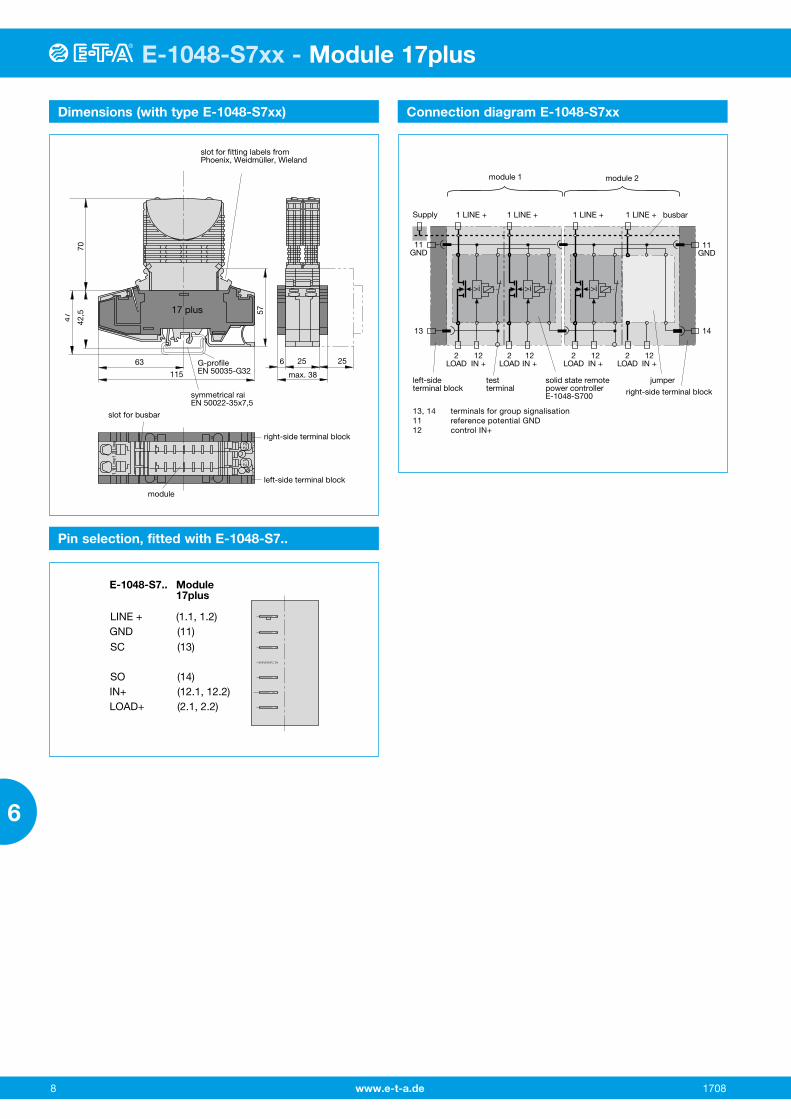
Dimensions (with type E-1048-S7xx)
13, 14 terminals for group signalisation11 reference potential GND12 control IN+
right-side terminal block
2LOAD
2LOAD
12IN +
>i
1 LINE + 1 LINE +
11GND
13
11GND
14
solid state remotepower controllerE-1048-S700
1 LINE + 1 LINE +
testterminal
2LOAD
12IN +
>i
12IN +
>i
2LOAD
12IN +
module 1 module 2
busbar
left-sideterminal block
jumper
Supply
E-1048-S7.. Module17plus
LINE + (1.1, 1.2)GND (11)SC (13)
SO (14)IN+ (12.1, 12.2)LOAD+ (2.1, 2.2)
Connection diagram E-1048-S7xx
Pin selection, fitted with E-1048-S7..
slot for busbar
module
right-side terminal block
left-side terminal block
slot for fitting labels fromPhoenix, Weidmüller, Wieland
63
symmetrical raiEN 50022-35x7,5
G-profileEN 50035-G32115
47 42,5
70
57
6 25 25
max. 38
11 14
17 plus
11 14
2.2
12.1
12.2
1.1
Line
1.2
Line
2.1
Modul 17plusFor technical data see section Power Distribution Systems

www.e-t-a.de
Module 17plus
91708
6
E-1048-S7xx - Module 17plus
Accessories
mounting dimensions
24ø1 7
mounting dimensions
61.5
60
45
Busbar 32 AX 222 005 01 blue insulation, 500 mm/19.68 in.X 222 005 02 red insulation, 500 mm/19.68 in.X 222 005 03 grey insulation, 500 mm/19.68 in.up to 32 A continuous load
Busbar 50 AY 307 016 01 non-insulated, 500 mm/19.68 in.up to 50 A continuous load;plugged in completely, protected against brush contact
Busbar 50 AY 307 016 11 non-insulated, 500 mm/19.68 in.up to 50 A continuous load
End bracketX 222 004 01Width 10 mm
Screw terminal for busbarX 211 156 01 non insulated(up to 35 mm2)
Retaining clip for circuit breaker 3600/3900recommended for fitting the devicesY 300 581 11
30
ø1 5.5
44.4
45
Retaining clip for circuit breaker 2210recommended for fitting single pole devicesY 302 974 21
.039
.945 .276
.039
1.18
.217
2.36
2.42
1.77
1.74
1.77
602.36
Labelsmarking area 6 x 10 mm(ordering unit 10 pcs = 1 strip)Y 307 942 61
blade terminalsDIN 46244-A 6.3-0.8
7
602.
36
010
.3
12.3
terminals 13+14bridged
SignalbrückeSignal loop
Germany
www.e-t-a.comS
igna
lbrü
cke
Sig
nal l
oo
p
xxxx
SB-S11-P1-01-1-1A
JumperSB-S11-P1-01-1-1A
.484
.406
2.76
top view
AC 240 V / DC 65 V, 1 A
1 213 14
8
2
5
18.5
4.5
Retaining clip Y 307 754 01recommended for tight fit of typesESS20 / ESX10
.728
.177
.315
.079
.197
642.52
64.5
2.54
Retaining clip Y 308 792 01recommended for tight fit of typesESX10 / E-1048-S6xx / SB-S11-P1-xxand terminal blocks type 17 and 17plus

www.e-t-a.de
Module 17plus
10 1708
6
Installation example for retaining clip
Removal of retaining clip Y 307 754 01
ESS20 with retaining clip Y 307 754 01for power distribution system module 17plus
All dimensions without tolerances are for reference only. In the interest of improved design, performance and cost effectiveness the right to make changes in these specifications wit-hout notice is reserved.Product markings may not be exactly as the ordering codes. Errors and omissions excepted.
Installation example for busbar
When mounting several modules side by side, proper insertion of the 32 A busbar X 222 005 01/02/03 has to be observed, i.e. the busbar must be pushed in evenly across the whole length from left to right, repeatedly if necessary. The groove of the busbar must be flush with the top edge of the Module 17plus.
Please ensure that the busbar audibly latches in into the Module 17plus.
top edge 17plus groovenose
Installation for busbar 32 A (X222 005 01/02/03) in Module 17plus