module 7 lesson 2 final - nptelnptel.ac.in/courses/105108070/module7/lecture16.pdf · ·...
TRANSCRIPT

Module 7/Lesson 2
1 Applied Elasticity for Engineers T.G.Sitharam & L.GovindaRaju
Module: 7 Torsion of Prismatic Bars 7.2.1 TORSION OF ELLIPTICAL CROSS-SECTION
Let the warping function is given by
Axy=y (7.15)
where A is a constant. This also satisfies the Laplace equation. The boundary condition gives
(Ay - y) 0)( =+-dSdx
xAxdSdy
or y (A-1) 0)1( =+-dSdx
AxdSdy
i.e., (A+1)2x 02)1( =--dSdy
yAdSdx
or 0])1()1[( 22 =--+ yAxAdSd
Integrating, we get
(1+A)x2+(1-A)y2 = constant.
This is of the form
12
2
2
2
=+by
ax
These two are identical if
AA
ba
+-
=11
2
2
or A = 22
22
abab
+-
Therefore, the function given by
y = xyabab
22
22
+-
(7.16)
represents the warping function for an elliptic cylinder with semi-axes a and b under torsion. The value of polar moment of inertia J is
J = ò ò -++ dxdyAyAxyx )( 2222 (7.17)

Module 7/Lesson 2
2 Applied Elasticity for Engineers T.G.Sitharam & L.GovindaRaju
= (A+1) ò ò ò ò-+ dxdyyAdxdyx 22 )1(
J = (A+1)Iy+(1-A)Ix (7.18)
where Ix = 4
3abp and Iy =
4
3bap
Substituting the above values in (7.18), we obtain
J = 22
33
baba+
p
But q = GJ
M
GI
M t
P
t =
Therefore, Mt = GJq
= Gq 22
33
baba+
p
or q = 33
22
baba
G
M t
p+
The shearing stresses are given by
tyz = Gq ÷÷ø
öççè
æ+
¶¶
xyy
= Mt 33
22
baba
p+
xabab
÷÷ø
öççè
æ+
+-
122
22
or tyz =ba
xM t3
2
p
Similarly, txz = 3
2
ab
yM t
p
Therefore, the resultant shearing stress at any point (x, y) is
t = 22xzyz tt + =
33
2
ba
M t
p [ ]212424 yaxb + (7.19)
Determination of Maximum Shear Stress
To determine where the maximum shear stress occurs, substitute for x2 from
12
2
2
2
=+by
ax
,
or x2 = a2 (1-y2/b2)
Module 7/Lesson 2
3 Applied Elasticity for Engineers T.G.Sitharam & L.GovindaRaju
and t = [ ] 2
1222242
33)(
2ybaaba
ba
M t -+p
Since all terms under the radical (power 1/2) are positive, the maximum shear stress occurs
when y is maximum, i.e., when y = b. Thus, maximum shear stress tmax occurs at the ends of the minor axis and its value is
tmax = 2/12433 )(
2ba
baM t
p
Therefore, tmax = 2
2abM t
p (7.20)
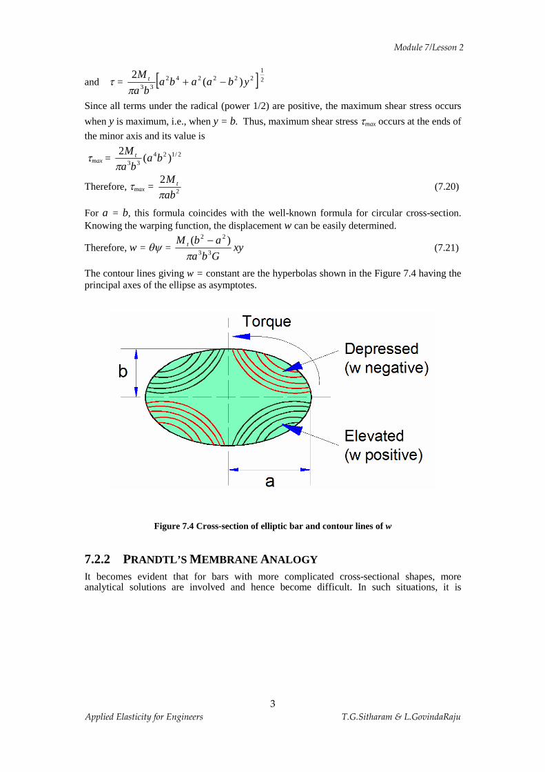
For a = b, this formula coincides with the well-known formula for circular cross-section. Knowing the warping function, the displacement w can be easily determined.
Therefore, w = qy = xyGba
abM t33
22 )(
p-
(7.21)
The contour lines giving w = constant are the hyperbolas shown in the Figure 7.4 having the principal axes of the ellipse as asymptotes.
Figure 7.4 Cross-section of elliptic bar and contour lines of w
7.2.2 PRANDTL’S MEMBRANE ANALOGY
It becomes evident that for bars with more complicated cross-sectional shapes, more analytical solutions are involved and hence become difficult. In such situations, it is
Module 7/Lesson 2
4 Applied Elasticity for Engineers T.G.Sitharam & L.GovindaRaju
desirable to use other techniques – experimental or otherwise. The membrane analogy introduced by Prandtl has proved very valuable in this regard.
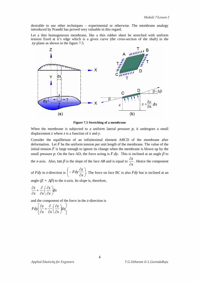
Let a thin homogeneous membrane, like a thin rubber sheet be stretched with uniform tension fixed at it’s edge which is a given curve (the cross-section of the shaft) in the xy-plane as shown in the figure 7.5.
Figure 7.5 Stretching of a membrane
When the membrane is subjected to a uniform lateral pressure p, it undergoes a small displacement z where z is a function of x and y.
Consider the equilibrium of an infinitesimal element ABCD of the membrane after deformation. Let F be the uniform tension per unit length of the membrane. The value of the initial tension F is large enough to ignore its change when the membrane is blown up by the small pressure p. On the face AD, the force acting is F.dy. This is inclined at an angle b to
the x-axis. Also, tan b is the slope of the face AB and is equal to xz¶¶
. Hence the component
of Fdy in z-direction is ÷øö
çèæ
¶¶
-xz
Fdy . The force on face BC is also Fdy but is inclined at an
angle (b + Db) to the x-axis. Its slope is, therefore,
dxxz
xxz
÷øö
çè涶
¶¶
+¶¶
and the component of the force in the z-direction is
úû
ùêë
é÷øö
çè涶
¶¶
+¶¶
dxxz
xxz
Fdy

Module 7/Lesson 2
5 Applied Elasticity for Engineers T.G.Sitharam & L.GovindaRaju
Similarly, the components of the forces Fdx acting on face AB and CD are
-Fdxyz¶¶
and Fdx úû
ùêë
鶶
¶¶
+¶¶
dyyz
yyz
)(
Therefore, the resultant force in z-direction due to tension F
= úû
ùêë
鶶
+¶¶
+¶¶
-úû
ùêë
鶶
+¶¶
+¶¶
- dyy
zyz
Fdxyz
Fdxdxx
zxz
Fdyxz
Fdy2
2
2
2
= F dxdyy
z
x
z÷÷ø
öççè
涶
+¶¶
2
2
2
2
But the force p acting upward on the membrane element ABCD is p dxdy, assuming that the membrane deflection is small.
Hence, for equilibrium,
F ÷÷ø
öççè
涶
+¶¶
2
2
2
2
y
z
x
z = -p
or 2
2
2
2
yz
xz
¶¶
+¶¶
= -p/F (7.22)
Now, if the membrane tension F or the air pressure p is adjusted in such a way that p/F becomes numerically equal to 2Gq, then Equation (7.22) of the membrane becomes identical to Equation (7.8) of the torsion stress function f. Further if the membrane height z remains zero at the boundary contour of the section, then the height z of the membrane becomes numerically equal to the torsion stress function f = 0. The slopes of the membrane are then equal to the shear stresses and these are in a direction perpendicular to that of the slope.
Further, the twisting moment is numerically equivalent to twice the volume under the membrane [Equation (7.14)].
Table 7.1 Analogy between Torsion and Membrane Problems
Membrane problem Torsion Problem Z f
S1
G
P 2q
yz
xz¶¶
¶¶
- , zxzy tt ,
2 (volume beneath membrane)
tM

Module 7/Lesson 2
6 Applied Elasticity for Engineers T.G.Sitharam & L.GovindaRaju
The membrane analogy provides a useful experimental technique. It also serves as the basis for obtaining approximate analytical solutions for bars of narrow cross-section as well as for member of open thin walled section.
7.2.3 TORSION OF THIN-WALLED SECTIONS
Consider a thin-walled tube subjected to torsion. The thickness of the tube may not be uniform as shown in the Figure 7.6.
Figure 7.6 Torsion of thin walled sections
Since the thickness is small and the boundaries are free, the shear stresses will be essentially parallel to the boundary. Let t be the magnitude of shear stress and t is the thickness.
Now, consider the equilibrium of an element of length D l as shown in Figure 7.6. The areas of cut faces AB and CD are t1 D l and t2 D l respectively. The shear stresses (complementary shears) are t1 and t2.
For equilibrium in z-direction, we have -t1 t1 D l + t2 t2 D l = 0 Therefore, t1 t1 = t2 t2 = q = constant
Hence the quantity t t is constant. This is called the shear flow q, since the equation is similar to the flow of an incompressible liquid in a tube of varying area.

Module 7/Lesson 2
7 Applied Elasticity for Engineers T.G.Sitharam & L.GovindaRaju
Determination of Torque Due to Shear and Rotation
Figure 7.7 Cross section of a thin-walled tube and torque due to shear
Consider the torque of the shear about point O (Figure 7.7). The force acting on the elementary length dS of the tube = DF = t t dS = q dS The moment arm about O is h and hence the torque = DMt = (qdS) h Therefore, DMt = 2qdA
where dA is the area of the triangle enclosed at O by the base dS.
Hence the total torque is
Mt = S 2qdA+
Therefore, Mt = 2qA (7.23)
where A is the area enclosed by the centre line of the tube. Equation (7.23) is generally
known as the "Bredt-Batho" formula.
To Determine the Twist of the Tube
In order to determine the twist of the tube, Castigliano's theorem is used. Referring to Figure 7.7(b), the shear force on the element is t t dS = qdS. Due to shear strain g, the force does work equal to DU
i.e., dt )(21
tdSU =D
= ltdS D.)(21 gt

Module 7/Lesson 2
8 Applied Elasticity for Engineers T.G.Sitharam & L.GovindaRaju
=G
ltdStt .).(
21
D (since gt G= )
= Gt
ldSt2
22 Dt
= Gt
ldSq2
2 D
= t
dSG
lq.
2
2D
t
dS
GA
lMU t .
8 2
2D=D
Therefore, the total elastic strain energy is
U = òD
tdS
GA
lM t2
2
8
Hence, the twist or the rotation per unit length ( lD = 1) is
q = tM
U¶¶
= ò tdS
GA
M t24
or q = ò tdS
GAqA
242
or q = ò tdS
AGq
2 (7.24)

Module 7/Lesson 2
9 Applied Elasticity for Engineers T.G.Sitharam & L.GovindaRaju
7.2.4 TORSION OF THIN-WALLED MULTIPLE-CELL CLOSED SECTIONS
Figure 7.8 Torsion of thin-walled multiple cell closed section
Consider the two-cell section shown in the Figure 7.8. Let A1 and A2 be the areas of the cells 1 and 2 respectively. Consider the equilibrium of an element at the junction as shown in the Figure 7.8(b). In the direction of the axis of the tube, we can write
-t1 t1 lD + t2 t2 lD + t3 t3 lD = 0 or t1 t1 = t2 t2 + t3 t3
i.e., q1 = q2 + q3
This is again equivalent to a fluid flow dividing itself into two streams. Now, choose moment axis, such as point O as shown in the Figure 7.9.

Module 7/Lesson 2
10 Applied Elasticity for Engineers T.G.Sitharam & L.GovindaRaju
Figure. 7.9 Section of a thin walled multiple cell beam and moment axis
The shear flow in the web is considered to be made of q1 and –q2, since q3 = q1 - q2. Moment about O due to q1 flowing in cell 1 (including web) is
1tM = 2q1A1
Similarly, the moment about O due to q2 flowing in cell 2 (including web) is
Mt 2 = 2q2 (A2+A1) - 2q2A1
The second term with the negative sign on the right hand side is the moment due to shear
flow q2 in the middle web.
Therefore, The total torque is
Mt = Mt 1 + Mt 2
Mt = 2q1A1 + 2q2A2 (a)
To Find the Twist (q)
For continuity, the twist of each cell should be the same.
We have
q = ò tdS
AGq
2
or 2Gq = ò tqdS
A1

Module 7/Lesson 2
11 Applied Elasticity for Engineers T.G.Sitharam & L.GovindaRaju
Let a1 = ò tdS
for Cell 1 including the web
a2 = ò tdS
for Cell 2 including the web
a12 = ò tdS
for the web only
Then for Cell 1
2Gq = )(1
212111
qaqaA
- (b)
For Cell 2
2Gq = )(1
112222
qaqaA
- (c)
Equations (a), (b) and (c) are sufficient to solve for q1, q2 and q.
7.2.5 NUMERICAL EXAMPLES
Example 7.1 A hollow aluminum tube of rectangular cross-section shown in Figure below, is subjected to a torque of 56,500 m-N along its longitudinal axis. Determine the shearing stresses and the angle of twist. Assume G = 27.6x10⁹ N/m2.
Figure 7.10
0.25
0.5
t1 t3
0.006t2=
0.006t4=0.012
All Dimensions in metre
Membrane Surface
A
B C p
D
Shear Flowq=
0.01

Module 7/Lesson 2
12 Applied Elasticity for Engineers T.G.Sitharam & L.GovindaRaju
Solution: The above figure shows the membrane surface ABCD
Now, the Applied torque =Mt = 2qA
56,500 = 2q(0.5x0.25)
56,500 = 0.25q
hence, q = 226000 N/m.
Now, the shearing stresses are
t1 = 26
1
/10833.18012.0
226000mN
tq
´==
t2 = 26
2
/10667.37006.0
226000mN
tq
´==
t3 = 26 /106.2201.0
226000mN´=
Now, the angle of twist per unit length is
q = ò tds
GAq
2
Therefore,
q = úûù
êëé ++
01.025.0
)2(006.0
5.0012.025.0
125.0x10x6.27x2226000
9
or q = 0.00696014 rad/m Example 7.2 The figure below shows a two-cell tubular section as formed by a conventional airfoil shape, and having one interior web. An external torque of 10,000 Nm is acting in a clockwise direction. Determine the internal shear flow distribution. The cell areas are as follows:
A1 = 680 cm2 A2 = 2000 cm2
The peripheral lengths are indicated in Figure
Solution:
For Cell 1, a1 = ò (t
dSincluding the web)
= 09.0
3306.0
67+
therefore, a1 = 148.3

Module 7/Lesson 2
13 Applied Elasticity for Engineers T.G.Sitharam & L.GovindaRaju
For Cell 2,
a2 = 08.0
6709.0
4809.0
6309.0
33+++
Therefore, a2 = 2409
For web,
a12 = 36609.0
33=
Now, for Cell 1,
2Gq = )(1
212111
qaqaA
-
= )3661483(6801
21 qq -
Therefore, 2Gq = 2.189q1 – 0.54q2 (i)
For Cell 2,
2Gq = )(1
112222
qaqaA
-
= )3662409(2000
112 qq -
Therefore, 2Gq = 1.20q2 – 0.18q1 (ii)
Equating (i) and (ii), we get
2.18 q1 – 0.54q2 = 1.20q2 – 0.18q1
or 2.36q1 – 1.74q2 = 0
or q2 = 1.36q1
The torque due to shear flows should be equal to the applied torque
Hence, from Equation (a), Mt = 2q1 A1 + 2q2 A2 10,000´ 100 = 2q1 x 680 + 2q2 x 2000 = 1360q1 + 4000q2
Substituting for q2, we get 10000´ 100 = 1360q1 + 4000´ 1.36q1

Module 7/Lesson 2
14 Applied Elasticity for Engineers T.G.Sitharam & L.GovindaRaju
Therefore, q1 = 147 N and q2 = 200 N
Figure 7.11
Example 7.3 A thin walled steel section shown in figure is subjected to a twisting moment T. Calculate the shear stresses in the walls and the angle of twist per unit length of the box.
Figure 7.12
Solution: Let A1 and 2A be the areas of the cells (1) and (2) respectively.
2
2
1
aA
p=\
( ) 22 422 aaaA =´=
For Cell (1),
tds
a ò=1 (Including the web)
÷øö
çèæ +
=t
aaa
21
p
For Cell (2),
tds
a ò=2
q2
q1 0.09cm
S=63cm
0.09cm S=67cm
0.08cm
S=67cm
S=
48cm
S=3
3cm
Cell-1
Cell-2
0.09cm
0.06cm
2a
2a a
A1
q2
q1
A2
t
t
t
t

Module 7/Lesson 2
15 Applied Elasticity for Engineers T.G.Sitharam & L.GovindaRaju
ta
ta
ta
ta 2222
+++=
÷øö
çèæ=\
ta
a8
2
For web,
÷øö
çèæ=
ta
a2
12
Now, For Cell (1),
( )212111
12 qaqa
AG -=q
( )
úû
ùêë
é÷øö
çèæ-
+= 212
222q
ta
qt
aaa
pp
( )[ ]212 222
qqtaa
-+= pp
( )[ ]21 222
2 qqat
G -+=\ pp
q )1(
For Cell (2),
( )112222
12 qaqa
AG -=q
úûù
êëé -= 122
284
1q
ta
qta
a
[ ]1224
42
qqta
a-=
[ ]12421
2 qqat
G -=\ q )2(
Equating (1) and (2), we get,
( )[ ] [ ]1221 421
222
qqat
qqat
-=-+pp
or ( )[ ] [ ]1221 421
222
qqqq -=-+pp

Module 7/Lesson 2
16 Applied Elasticity for Engineers T.G.Sitharam & L.GovindaRaju
( )[ ] [ ]1221 4224
qqqq -=-+pp
( )04
8241221 =+--
+\ qqqq
ppp
( )04
81
2421 =úû
ùêëé +-úû
ùêëé +
ppp
( )0
482421 =úû
ùêëé +
-úûù
êëé ++
qqpp
ppp
or ( ) ( ) 21 4884 qq ppp +=++
12 8485
qq ÷øö
çèæ
++
=\pp
But the torque due to shear flows should be equal to the applied torque. i.e., 2211 22 AqAqT += )3(
Substituting the values of 12 , Aq and 2A in (3), we get,
21
2
1 4.8485
22
2 aqa
qT ÷øö
çèæ
++
+÷÷ø
öççè
æ=
ppp
12
12
8485
8 qaqa ÷øö
çèæ
++
+=ppp
( )( ) 1
22
21612
qa
T úû
ùêë
é+
++=\
ppp
( )( )1612
2221 +++
=\pp
pa
Tq
Now, from equation (1), we have,
( ) ( )( )
( )( )úû
ùêë
é++
+÷øö
çèæ
++
-++
++=
1612
28485
21612
22
22
2222 ppp
pp
ppp
pp
qa
T
a
Tat
G
Simplifying, we get the twist as ( )( )úû
ùêë
é++
+=
16122
3223 ppp
qtGa
T

Module 7/Lesson 2
17 Applied Elasticity for Engineers T.G.Sitharam & L.GovindaRaju
Example 7.4 A thin walled box section having dimensions taa ´´2 is to be compared with a solid circular section of diameter as shown in the figure. Determine the thickness t so that the two sections have:
(a) Same maximum shear stress for the same torque. (b) The same stiffness.
Figure 7.13 Solution: (a) For the box section, we have
aatT
At
qAT
´===
2...2
...2
2
tt
taT
24=\t )(a
Now, For solid circular section, we have
rIT
p
t=
Where Ip = Polar moment of inertia
÷øö
çèæ
=
÷÷ø
öççè
æ\
232
4 aa
T tp
aaT
ort
p232
4=
÷øö
çèæ=\ 3
16aT
pt )(b
Equating (a) and (b), we get
32
164 a
Tta
Tp
= TatTa 3264 p=\
64a
tp
=\
(b) The stiffness of the box section is given by
a. 2a
t a
Module 7/Lesson 2
18 Applied Elasticity for Engineers T.G.Sitharam & L.GovindaRaju
tds
GAqò=
2q
Here T = 2qA A
Tq
2=\
úûù
êëé +++=\
ta
ta
ta
ta
GAT 22
4 2q
( ) taG
aTtGA
aT
22
2
24
646
=
=
GtaaT
4166
=\q )(c
The stiffness of the Solid Circular Section is
44
32
32
aGT
aG
TGIT
p ppq =
÷÷ø
öççè
æ== )(d
Equating (c) and (d), we get
44
3216
6aGT
GtaaT
p=
p32
166
=t
a
32166´
=\a
tp
÷øö
çèæ=\
6443 a
tp

Module 7/Lesson 2
19 Applied Elasticity for Engineers T.G.Sitharam & L.GovindaRaju
Example 7.5 A two-cell tube as shown in the figure is subjected to a torque of 10kN-m. Determine the Shear Stress in each part and angle of twist per metre length. Take modulus of rigidity of the material as 83 kN/mm2.
All dimensions in mm
Figure 7.14
Solution: For Cell 1 Area of the Cell = A1= 215000100150 mm=´
tds
a ò=1 (including web)
1305
1005.2
1505
1005
150
=
+++=
For Cell 2
Area of the cell = ( ) ( )222 75125150
21
-´´=A
= 7500mm2
tds
a ò=\ 2 (including web)
5.2
1255.2
1255.2
150++=
1602 =\a
For the web,
605.2
15012 ==a
150
100
125
1255
2.5
2.5
2.5q1
q2
Mt

Module 7/Lesson 2
20 Applied Elasticity for Engineers T.G.Sitharam & L.GovindaRaju
For Cell (1)
( )212111
12 qaqa
AG -=q
( )21 6013015000
12 qqG -=\ q )(a
For Cell (2)
( )112222
12 qaqa
AG -=q
( )12 601607500
1qq -= )(b
Equating (a) and (b), we get
( )1221 601607500
1)60130(
150001
qqqq -=-
Solving, 21 52.1 qq = )(c
Now, the torque due to shear flows should be equal to the applied torque.
i.e., 2211 22 AqAqM t +=
)7500(2)15000(21010 216 qq +=´ )(d
Substituting (c) in (d), we get
)7500(2)52.1(1500021010 226 qq +´=´
Nq 02.1652 =\
Nq 83.25002.16552.11 =´=\
Shear flow in the web = ( ) ( )02.16583.250213 -=-= qqq
Nq 81.853 =\
2
1
11 /17.50
583.250
mmNtq
===\t
2
2
22 /01.66
5.202.165
mmNtq
===t
2
3
33 /32.34
5.281.85
mmNtq
===t
Now, the twist q is computed by substituting the values of q1 and q2 in equation (a)

Module 7/Lesson 2
21 Applied Elasticity for Engineers T.G.Sitharam & L.GovindaRaju
i.e., [ ]02.1656083.25013015000
12 ´´´=qG
lengthmmradians /10824.1100083
7.2270615000
1 5-´=´
´=\q
04.1=qor degrees/m length Example 7.6 A tubular section having three cells as shown in the figure is subjected to a torque of 113 kN-m. Determine the shear stresses developed in the walls of the section.
All dimensions in mm
Figure 7.15
Solution: Let 654321 ,,,,, qqqqqq be the shear flows in the various walls of the tube as
shown in the figure. 321 ,, AandAA be the areas of the three cells.
( ) 221 25322127
2mmA ==\
p
22 64516254254 mmA =´=
23 64516mmA =
Now, From the figure, q1 = q2 + q4
q2 = q3 + q5
q3 = q6 or 4422111 tttq ttt +==
66333
5533222
ttq
tttq
ttttt
==+==
(1)
Where 654321 ,,,, tttttt and are the Shear Stresses in the various walls of the tube.
Now, The applied torque is
254 254
254
q1
q6
q3
q3
q4
q2
q2
(1) (2) (3)
0.8
0.8
1.3 1.0
127
0.6
q5

Module 7/Lesson 2
22 Applied Elasticity for Engineers T.G.Sitharam & L.GovindaRaju
( )333222111
332211
2
222
tAtAtA
qAqAqAM t
ttt ++=++=
i.e., ( ) ( ) ( )[ ]8.0645168.0645168.025322210113 216 ´+´+´=´ tt
( ) 3718397.3 321 =++\ ttt (2)
Now, considering the rotations of the cells and 654321 ,,,, SandSSSSS as the length of cell
walls,
We have,
3663355
2552244
14411
22
22
2
AGSSS
AGSSS
AGSS
qtttqttt
qtt
=++-=++-
=+ (3)
Here ( ) mmS 3981271 =´= p
mmSSSSS 25465432 =====
\(3) can be written as
qtttqttt
qt
G
G
GS
645162542542254
645162542542254
25322254398
632
522
41
=+´´+-=+´´+-
=+ (4)
Now, Solving (1), (2) and (4) we get
21 /4.40 mmN=t
22 /2.55 mmN=t
23 /9.48 mmN=t
24 /7.12 mmN-=t
26 /6.36 mmN=t