module3 temperature sensors
TRANSCRIPT
Measurements & Instrumentation
Module 3: Temperature Sensors
PREPARED BY
Academic Services Unit
August 2013
© Institute of Applied Technology, 2013
ATE 314– Measurements & Instrumentation
Module 3: Temperature Sensors 2
Module 3: Temperature Sensors Module Objectives Upon successful completion of this module, students should be able to:
1. Explain the role of sensors/transducers in a measurement system
2. Define the terms sensitivity and linearity of a sensor/transducer
3. Identify different sensors used in temperature measurements
4. Determine the sensor characteristics through experiments
5. Understand and perform calibration of temperature
sensor/transducer.
Module Contents: Topic Page No.
3.1 Introduction to Instrumentation Systems 3
3.2 Measurement System Elements 4
3.3 Temperature Measurement 7
3.4 Lab Activity 1 11
3.5 Review Exercise 15
ATE 314– Measurements & Instrumentation
Module 3: Temperature Sensors 3
3.1 Introduction to Instrumentation Systems
We use the term ‘measurements’ everyday in our lives. We make
measurements while performing the following everday tasks:
• Noting the time on our watch/clock
• Recording the temperature
• Tracing the speed of a car
• Estimating electricity consumption, and so on
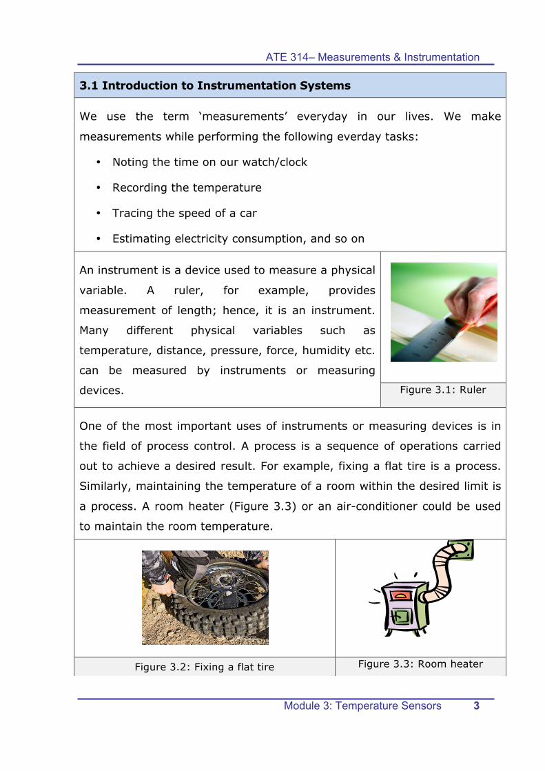
An instrument is a device used to measure a physical
variable. A ruler, for example, provides
measurement of length; hence, it is an instrument.
Many different physical variables such as
temperature, distance, pressure, force, humidity etc.
can be measured by instruments or measuring
devices.
Figure 3.1: Ruler
One of the most important uses of instruments or measuring devices is in
the field of process control. A process is a sequence of operations carried
out to achieve a desired result. For example, fixing a flat tire is a process.
Similarly, maintaining the temperature of a room within the desired limit is
a process. A room heater (Figure 3.3) or an air-conditioner could be used
to maintain the room temperature.
Figure 3.2: Fixing a flat tire Figure 3.3: Room heater
ATE 314– Measurements & Instrumentation
Module 3: Temperature Sensors 4
Fixing a tire is a manual process, whereas, the process of maintaining the
room temperature is an automatic process. However, the fundamental
part of any process control system is a measurement system.
3.2 Measurement System Elements
Any Measurement system consists of three basic parts:
Ø transducer/sensor
Ø signal processor and
Ø recorder/display
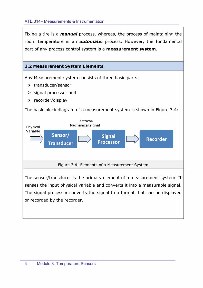
The basic block diagram of a measurement system is shown in Figure 3.4:
Figure 3.4: Elements of a Measurement System
The sensor/transducer is the primary element of a measurement system. It
senses the input physical variable and converts it into a measurable signal.
The signal processor converts the signal to a format that can be displayed
or recorded by the recorder.
Sensor/ Transducer
Signal Processor Recorder
Electrical/ Mechanical signal Physical
Variable
ATE 314– Measurements & Instrumentation
Module 3: Temperature Sensors 5
Sensor
A sensor is a device that senses a physical variable, such as temperature,
force, or pressure etc. Sensing the variable means detecting the presence
of the variable as well as to what degree it is present. For example, a
human finger is a sensor that can tell you whether an object is hot or cold,
but a thermometer can determine accurately to what degree the
temperature is present.
Figure 3.5: Thermometer
Transducer
A transducer is a device that converts a physical quantity into a measurable
quantity, usually an electrical signal. Examples of transducers include
microphones and thermocouples. A microphone converts sound energy
into electrical energy, whereas, a thermocouple converts heat energy into
electrical energy.
Figure 3.6: Thermocouple Figure 3.7: Microphone
Sensors are mostly an integral, built-in part of a transducer.
ATE 314– Measurements & Instrumentation
Module 3: Temperature Sensors 6
Skill 1: Sensor/Transducer Characteristics
As indicated previously, sensors/transducers are the primary elements of
any measurement system. In Module 1 you studied few of the
characteristics of these sensing instruments. Try to recall some of these
characteristics by completing the following table.
Characteristic Definition
Linearity
Sensitivity
Accuracy
Precision
Range
ATE 314– Measurements & Instrumentation
Module 3: Temperature Sensors 7
3.3 Temperature Measurement
Temperature is the degree of hotness or coldness
measured on a definite scale. The various units for
measuring temperature are Celsius, Kelvin and
Fahrenheit. The SI unit of temperature measurement is
the ‘Kelvin’.
Figure 3.8
Temperature can be measured using any one of the following methods
depending on the application:
1. Immersion in a gas or liquid
2. Surface Contact with the solid
3. No contact
There are various temperature measuring devices such
as meters, gauges, or transducers, that could be used
based on the measurement method and application. In
this module, you will study the thermometer, thermistor,
RTD and the thermocouple.
Figure 3.9
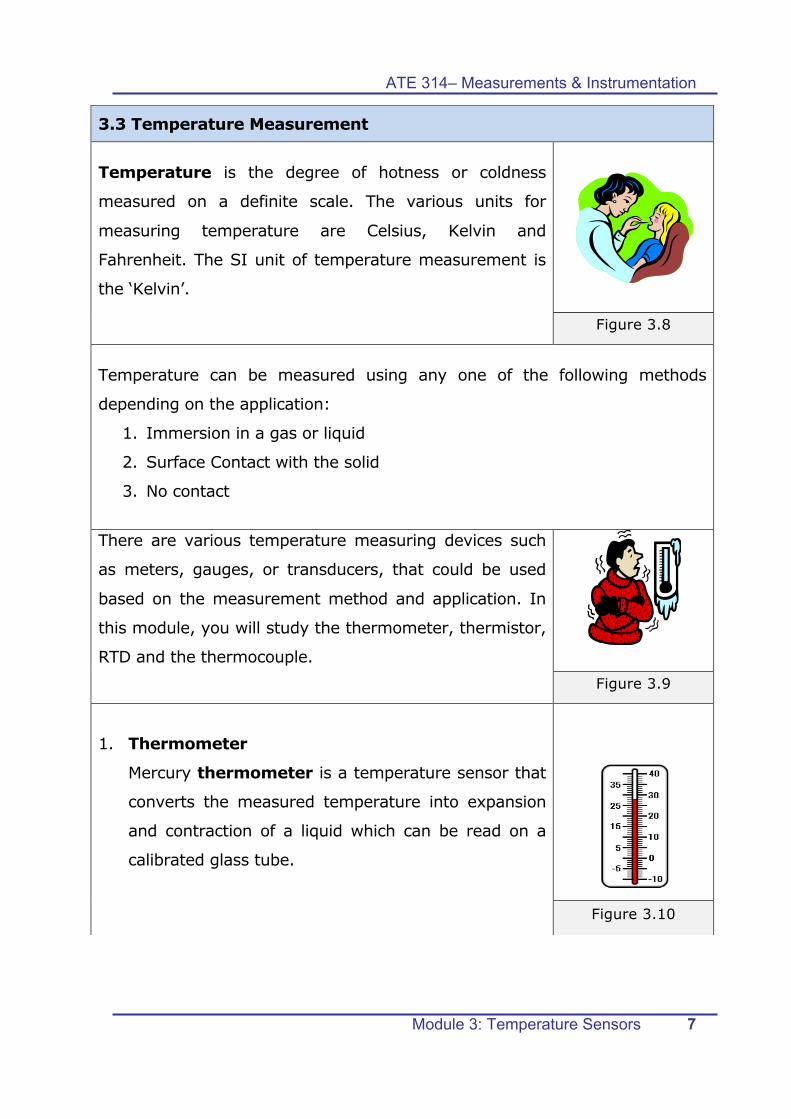
1. Thermometer
Mercury thermometer is a temperature sensor that
converts the measured temperature into expansion
and contraction of a liquid which can be read on a
calibrated glass tube.
Figure 3.10
ATE 314– Measurements & Instrumentation
Module 3: Temperature Sensors 8
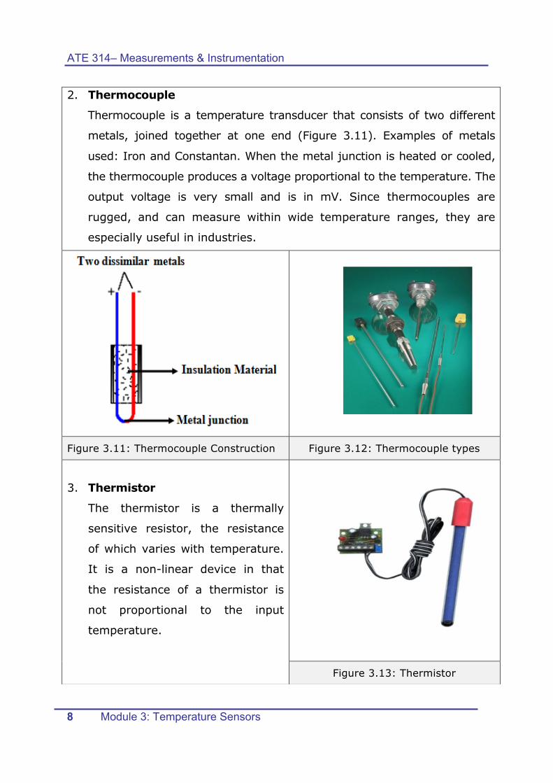
2. Thermocouple
Thermocouple is a temperature transducer that consists of two different
metals, joined together at one end (Figure 3.11). Examples of metals
used: Iron and Constantan. When the metal junction is heated or cooled,
the thermocouple produces a voltage proportional to the temperature. The
output voltage is very small and is in mV. Since thermocouples are
rugged, and can measure within wide temperature ranges, they are
especially useful in industries.
Figure 3.11: Thermocouple Construction Figure 3.12: Thermocouple types
3. Thermistor
The thermistor is a thermally
sensitive resistor, the resistance
of which varies with temperature.
It is a non-linear device in that
the resistance of a thermistor is
not proportional to the input
temperature.
Figure 3.13: Thermistor
ATE 314– Measurements & Instrumentation
Module 3: Temperature Sensors 9
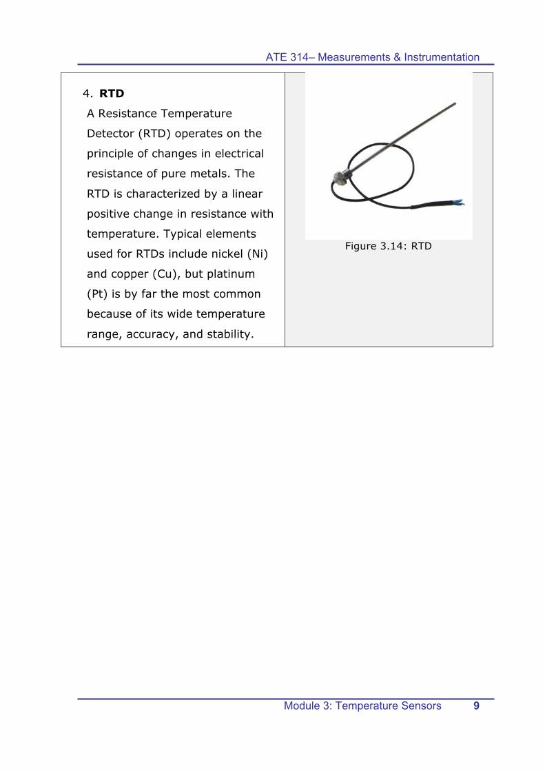
4. RTD
A Resistance Temperature
Detector (RTD) operates on the
principle of changes in electrical
resistance of pure metals. The
RTD is characterized by a linear
positive change in resistance with
temperature. Typical elements
used for RTDs include nickel (Ni)
and copper (Cu), but platinum
(Pt) is by far the most common
because of its wide temperature
range, accuracy, and stability.
Figure 3.14: RTD
ATE 314– Measurements & Instrumentation
Module 3: Temperature Sensors 10
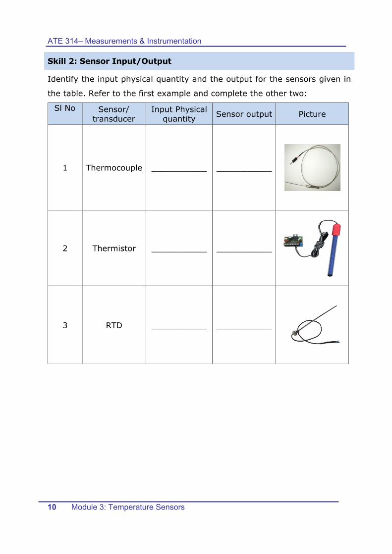
Skill 2: Sensor Input/Output
Identify the input physical quantity and the output for the sensors given in
the table. Refer to the first example and complete the other two:
Sl No Sensor/ transducer
Input Physical quantity Sensor output Picture
1 Thermocouple ___________ ___________
2 Thermistor ___________ ___________
3 RTD ___________ ___________
ATE 314– Measurements & Instrumentation
Module 3: Temperature Sensors 11
3.4 Lab Activity
You will be given three unknown temperature sensors: thermocouple,
thermistor and RTD sensors. Use the following equipment to design and
perform an experimental setup to do the following tasks:
1) Identify the name of the given sensors, their inputs and outputs
2) Plot the temperature curve of each sensor
3) Identify the relationship between the input and output of each
sensor.
4) Determine the linearity of each sensor
5) Obtain the calibration equation of linear sensors
List of Equipment:
• Heat Bar System
• Calibration Tank
• Thermometer
• Set of various temperature sensors
• Multimeter
Procedure:
Step 1: Based on the knowledge acquired in Module 1, draw the setup of
your experiment
ATE 314– Measurements & Instrumentation
Module 3: Temperature Sensors 12
Step 2: Describe the main steps of the experiment
_____________________________________________________
_____________________________________________________
_____________________________________________________
_____________________________________________________
_____________________________________________________
Step 3: Label Each Sensor as Sensor 1, Sensor 2 and Sensor 3
Step 4: Perform the experiment
Step 5: Fill the following Tables:
Sensor No. Input Output
Sensor 1
Sensor 2
Sensor 3
Sensor 1 Sensor 2 Sensor 3
Input
Reading
Output
Reading
Input
Reading
Output
Reading
Input
Reading
Output
Reading
ATE 314– Measurements & Instrumentation
Module 3: Temperature Sensors 13
Step 6: Use Microsoft Excel to plot the temperature curve of each sensor.
Sensor 1
Temperature Curve
Sensor 2
Temperature Curve
Sensor 3
Temperature Curve
Step 7: use the curves drawn from step 6 to fill the following table:
Sensor Number Linearity Input/Output Relationship
Sensor 1
Sensor 2
Sensor 3
mm
Step 8: for linear sensors only, obtain the calibration equation of that
sensor. Then, check your answers by using Microsoft Excel.
1. Hint: to obtain the calibration equation in Excel, right click on the
graph à Add trendline à display equation on chart
_______________________________________________________
_______________________________________________________
_______________________________________________________
_______________________________________________________
_______________________________________________________
ATE 314– Measurements & Instrumentation
Module 3: Temperature Sensors 14
Step 9: Identify the name of each sensor based on the above results.
Justify your answer:
Sensor No. Sensor Name Justification
Sensor 1
Sensor 2
Sensor 3
Question:
• List one application for each sensor
Sensor No. Application
Sensor 1
Sensor 2
Sensor 3
ATE 314– Measurements & Instrumentation
Module 3: Temperature Sensors 15
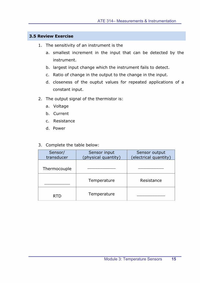
3.5 Review Exercise
1. The sensitivity of an instrument is the
a. smallest increment in the input that can be detected by the
instrument.
b. largest input change which the instrument fails to detect.
c. Ratio of change in the output to the change in the input.
d. closeness of the ouptut values for repeated applications of a
constant input.
2. The output signal of the thermistor is:
a. Voltage
b. Current
c. Resistance
d. Power
3. Complete the table below:
Sensor/ transducer
Sensor input (physical quantity)
Sensor output (electrical quantity)
Thermocouple ___________ __________
__________ Temperature Resistance
RTD Temperature ___________
ATE 314– Measurements & Instrumentation
Module 3: Temperature Sensors 16
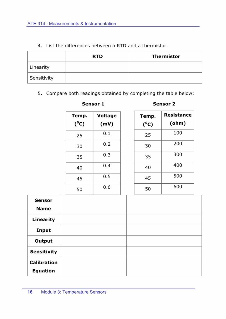
4. List the differences between a RTD and a thermistor.
RTD Thermistor
Linearity
Sensitivity
5. Compare both readings obtained by completing the table below:
Sensor 1 Sensor 2
Temp.
(0C)
Voltage
(mV)
25 0.1
30 0.2
35 0.3
40 0.4
45 0.5
50 0.6
Temp.
(0C)
Resistance
(ohm)
25 100
30 200
35 300
40 400
45 500
50 600
Sensor
Name
Linearity
Input
Output
Sensitivity
Calibration
Equation
ATE 314– Measurements & Instrumentation
Module 3: Temperature Sensors 17
Notes