molbox rfm - cole-parmer rfm ™ reference flow ... a second model, molbox1, is available for...
TRANSCRIPT

Technical Data
Features• Compact presentation• Covers the flow range of 1 sccm to
100 slm with molbloc-L, and up to 5000 slm with molbloc-S
• Select from 20 different gases with molbloc-L and 10 with molbloc-S
• Accredited measurement uncertainty of ± 0.5 % of reading with 100:1 rangeability
• Internal valving for on-board purge, leak test and tare support
• Includes advanced measurement functions such as totalize, average, hi/lo and deviation
• Complete front panel control and RS232 and IEEE-488 remote communications
• Measures mass and volume flow with user setable reference pressure and temperature conditions
molbox RFM ™ Reference Flow Monitor
molbox RFM is a support unit for making mass flow mea-surements using molbloc-L laminar and molbloc-S sonic flow elements.
molbloc flow elements are connected to molbox RFM with two pressure connections and one data line. molbox RFM reads calibration data off the molbloc EEPROM and measures molbloc upstream and downstream pressure with its built-in high accuracy Reference Pressure Transducers (RPTs). An ohmic measurement system reads the resistance of the molbloc platinum resistance ther-mometers from which molbloc temperature is calculated. Using
the molbloc calibration data, pressures, temperature and gas properties stored in molbox RFM memory, the flow rate of the gas flowing through the molbloc is calculated. For molbloc-L flow elements, a microrange option is available to increase flow measurement resolution and accuracy under 10 % FS of the flow range.
molbox RFM and molbloc flow elements are useful in a variety of measurement, test and cali-bration applications in which highly accurate measurement of low gas flows where maximum accuracy is the most notable specification is needed. molbox RFM is specifically designed for
applications in which a highly compact presentation, great rangeability and reduced cost are the primary considerations. A second model, molbox1, is available for applications in which lowest possible uncer-tainty is the top priority.
To configure your mass flow calibration system, see the pages that follow to select the molbloc and pressure depen-dent calibrations to best cover your flow ranges and pressure conditions. molstic mounting systems and COMPASS® for molbox calibration software are available to complete the system (see molstic and COMPASS product brochures).

2 Fluke Corporation molbox RFM™ Reference flow monitor
molbox RFM measures the flow through molbloc flow elements. The flow range, usable operating pressure, and differential pressure for molbloc-L, or the flow range and absolute pressure range for molbloc-S, depend on the molbloc element used and the calibration options. For molbloc-L ranges up to 3E4, the resolution and accuracy under 10 % FS are improved by the microrange option. For the 1E5-L molbloc, the microrange option is necessary to achieve the specification.
Flow measurement specifications
molbloc-S (all ranges)Specifications are the same as a molbox RFM without Microrange. The Microrange trans-ducer is disabled whenever the molbox RFM is connected to a molbloc-S.
1 Precision: Combined linearity, hysteresis, repeatability.2 Predicted Stability: Maximum change in zero and span over one year for typical molbox RFM
and molbloc used under typical conditions. As stability can only be predicted, stability for a specific molbox RFM should be established from experience.
3 Measurement Uncertainty: Maximum deviation of the molbox RFM flow indication from the true value of the flow through the molbloc including precision, stability and DHI calibration standard uncertainty. Measurement uncertainty specifications for molblocs are valid only for gases with which the molbloc has been calibrated. All molblocs are calibrated for N2. Calibrations with other gases are optional. DHI calibration capability is not maintained at all times for all gases on all molbloc designations. Check for availability before ordering.
molbox RFM
molbloc-L (ranges 1E1-L thru 3E4-L) molbloc-S (all ranges)
Measurement update rate
1 second 1 second
Range 0 to molbloc full scale depending on gas and molbloc pressure dependent calibration type (see molbloc-L tables)
The flow related to 20 kPa to 200 kPa absolute (3 psia to 30 psia) or 50 kPa to 500 kPa absolute (7 psia to 70 psia) upstream (see molbloc-S table)
Resolution 0.01 % FS ± 0.01 % of reading
Linearity ± 0.23 % of reading from 10 % to 100 % FS, ± 0.023 % FS under 10 % FS
± 0.25 % of reading
Repeatability ± 0.1% of reading from 10 % to 100 % FS, ± 0.01% FS under 10 % FS
± 0.1 % of reading
Precision1 ± 0.25 % of reading from 10 % to 100 % FS, ± 0.025 % FS under 10 % FS
± 0.3 % of reading
Predicted stability2 (one year)
± 0.15 % of reading from 10 % to 100 % FS, ± 0.015 % FS under 10 % FS
± 0.2 % of reading
Measurement uncertainty3
± 0.5 % of reading from 10 % to 100 % FS, ± 0.05 % FS under 10 % FS
± 0.5 % of reading from 50 kPa to 500 kPa, ± 0.5 % of the flow @ 50 kPa from 20 kPa to 50 kPa
molbox RFM with Microrange option
molbloc-L (ranges 1E1-L thru 3E4-L) molbloc-L (ranges 1E5 only)
Measurement update rate
1 second 1 second
Range 0 to molbloc full scale depending on gas and molbloc pressure dependent calibration type (see molbloc-L tables)
0 to molbloc full scale depending on gas and molbloc pressure dependent calibration type (see molbloc-L tables)
Resolution 0.01 % FS, 0.001 % FS under 10 % FS 0.01 % FS
Linearity ± 0.23 % of reading from 1 % to 100 % FS, ± 0.0023 % FS under 1 % FS
± 0.25 % of reading from 5 % to 100 % FS, ± 0.0125 % FS under 5 % FS
Repeatability ± 0.1 % of reading from 1 % to 100 % FS, ± 0.001 % FS under 1 % FS
± 0.2 % of reading from 5 % to 100 % FS, ± 0.01 % FS under 5% FS
Precision1 ± 0.25 % of reading from 1 % to 100 % FS, ± 0.0025 % FS under 1% FS
± 0.32 % of reading from 5 % to 100 % FS, ± 0.016 % FS under 5 % FS
Predicted stability2 (one year)
± 0.15 % of reading from 1 % to 100 % FS, ± 0.0015 % FS under 1 % FS
± 0.2 % of reading from 5 % to 100 % FS, ± 0.01 % FS under 5 % FS
Measurement uncertainty3
± 0.5 % of reading from 1 % to 100 % FS, ± 0.005 % FS under 1 % FS
± 0.5 % of reading from 5 % to 100 % FS, ± 0.025 % FS under 5 % FS

3 Fluke Corporation molbox RFM™ Reference flow monitor
molbloc-S designator, KF (sccm/kPa), and full scale flow (slm @ 0°C)
Designotor 1E1-S 2E1-S 5E1-S 1E2-S 2E2-S 5E2-S 1E3-S 2E3-S 5E3-S 1E4-S
KF (sccm/kPa) 10 20 50 100 200 500 1000 2000 5000 10000
Gases Ratio Cal type
Iner
t
Nitrogen N2 1.000 SP 5.00 10.00 25.0 50.0 100.0 250.0 500 1000 2500 5000LP 2.00 4.00 10.0 20.0 40.0 100.0 200 400 1000 2000
minimum 2.00 3.50 7.7 15.0 28.0 67.0 129 248 596 1173Argon Ar 0.837 SP 4.19 8.37 20.9 41.9 83.7 209.3 419 837 2093 4186
LP 1.67 3.35 8.4 16.7 33.5 83.7 167 335 837 1674minimum 1.67 3.00 6.9 13.9 24.3 61.0 122 245 526 1053
Helium He 2.647 SP 13.23 26.47 66.2 132.3 264.7 661.7 1323 2647 6617 13234LP 5.29 10.59 26.5 52.9 105.9 264.7 529 1059 2647 5294
minimum 9.00 16.00 29.7 54.1 98.0 218.4 383 768 1928 3865Sulfur hexafluoride SF6 0.435 SP 2.17 4.35 10.9 21.7 43.5 108.7 217 435 1087 2174
LP 0.87 1.74 4.3 8.7 17.4 43.5 87 174 435 870minimum 0.63 1.10 2.7 5.5 10.9 23.4 47 94 235 471
Xenon Xe 0.460 SP 2.30 4.60 11.5 23.0 46.0 115.1 230 460 1151 2302LP 0.92 1.84 4.6 9.2 18.4 46.0 92 184 460 921
minimum 0.80 1.50 3.3 6.7 13.4 33.7 58 116 290 580
Flam
mab
le
Ethane1 C2H6 0.996 SP 4.80 9.60 24.0 48.0 96.0 240.1 480 960 2401 4802LP 1.92 3.84 9.6 19.2 38.4 96.0 192 384 960 1921
minimum 1.40 2.80 6.2 12.4 24.9 62.4 107 214 537 1074Ethylene1 C2H4 3.730 SP 4.98 9.96 24.9 49.8 99.6 248.9 498 996 2489 4979
LP 1.99 3.98 10.0 19.9 39.8 99.6 199 398 996 1992minimum 1.70 3.00 6.5 13.1 26.2 65.8 113 226 565 1132
Hydrogen H2 1.320 SP 18.65 37.30 93.2 186.5 373.0 932.4 1865 3730 9324 18649LP 7.46 14.92 37.3 74.6 149.2 373.0 746 1492 3730 7460
minimum 10.50 15.80 36.1 65.2 116.2 255.0 512 1026 2573 4415Methane CH4 0.789 SP 6.60 13.20 33.0 66.0 132.0 330.0 660 1320 3300 6601
LP 2.64 5.28 13.2 26.4 52.8 132.0 264 528 1320 2640minimum 2.64 4.50 10.0 17.6 35.3 88.6 178 304 763 1527
Propane1 C3H8 0.563 SP 3.94 7.89 19.7 39.4 78.9 197.2 394 789 1972 3944LP 1.58 3.15 7.9 15.8 31.5 78.9 158 315 789 1577
minimum 1.16 2.00 5.0 10.0 20.0 42.9 86 172 431 862
Fluo
ro-c
arb
ons
Carbon tetrafluoride1 CF4 0.447 SP 2.81 5.63 14.1 28.1 56.3 140.7 281 563 1407 2814LP 1.13 2.25 5.6 11.3 22.5 56.3 113 225 563 1126
minimum 0.84 1.60 3.6 7.2 14.5 36.3 62 125 312 624Hexafluoroethene1 C2F6 0.629 SP 2.24 4.47 11.2 22.4 44.7 111.8 224 447 1118 2237
LP 0.89 1.79 4.5 8.9 17.9 44.7 89 179 447 895minimum 0.65 1.10 2.8 5.6 11.2 24.1 48 96 241 483
Trifluoromethane1 CHF3 0.983 SP 3.15 6.29 15.7 31.5 62.9 157.3 315 629 1573 3147LP 1.26 2.52 6.3 12.6 25.2 62.9 126 252 629 1259
minimum 0.95 1.90 4.1 8.2 16.3 41.0 70 141 352 705
Oth
er
Air Air 0.795 SP 4.92 9.83 24.6 49.2 98.3 245.9 492 983 2459 4917LP 1.97 3.93 9.8 19.7 39.3 98.3 197 393 983 1967
minimum 1.97 3.40 7.7 15.0 28.0 67.0 129 248 596 1173Carbon dioxide CO2 1.000 SP 3.98 7.95 19.9 39.8 79.5 198.8 398 795 1988 3977
LP 1.59 3.18 8.0 15.9 31.8 79.5 159 318 795 1591minimum 1.40 2.40 6.0 10.6 21.2 53.2 91 183 458 916
Carbon monoxide CO 0.795 SP 5.00 10.00 25.0 50.0 100.0 250.0 500 1000 2500 5000LP 2.00 4.00 10.0 20.0 40.0 100.0 200 400 1000 2000
minimum 2.00 3.50 7.8 15.6 27.4 68.7 138 276 592 1186Nitrous oxide N2O 0.367 SP 3.98 7.95 19.9 39.8 79.5 198.8 398 795 1988 3976
LP 1.59 3.18 8.0 15.9 31.8 79.5 159 318 795 1590minimum 1.40 2.40 6.0 10.6 21.1 53.0 91 182 456 912
Octafluorocyclobutane1 C4F8 0.935 SP2 n/a n/a n/a n/a n/a n/a n/a n/a n/a n/aLP 0.73 1.47 3.7 7.3 14.7 36.7 73 147 367 733
minimum n/a n/a n/a n/a n/a n/a n/a n/a n/a n/aOxygen O2 SP 4.68 9.35 23.4 46.8 93.5 233.9 468 935 2339 4677
LP 1.87 3.74 9.4 18.7 37.4 93.5 187 374 935 1871minimum 1.87 3.20 7.3 14.6 25.6 64.2 129 258 553 1107
Ratio = Inverse square root density ratio of the current gas to nitrogen KF = Pressure to flow conversion ratio, sccm/kPaTo estimate a flow in a given gas at a given pressure: Flow(slm) = KF * pressure in kPa absolute/1000 * Gas Ratio
Cal types:SP = Standard Pressure calibration 50 kPa to 500kPa absolute; table shows flow @ 500 kPa, flow @ 50 kPa is 10 % of value shown.LP = Low Pressure calibration 20 kPa to 200 kPa; table shows flow @ 200 kPa, flow @ 20 kPa is 10 % of value shown. minimum = table shows estimated minimum flow without vacuum if atmopheric pressure is ~ 100 kPa
Note: Non-Standard Pressure (NSP) calibrations are available up to 600 kPa absolute
1 This gas is not currently supported by the molbox RFM2 The vapor pressure of octafluorocyclobutane is
230 kPa absolute, SP operation is not possible
All flows are nominal and approximate; in gases other than N2 and Air, flows may vary up to 10 % due to differences in characteristics and manufacturing
The operating range of molbloc-S is dependent upon the absolute upstream pressure. Two different calibration options are offered to accommodate the requirement of the user's application. The Standard Pressure (SP) calibration of 50 kPa to 500 kPa absolute (7 psia to 70 psia) gives the most flexibility and allows partial use of the range without a vacuum. The Low Pressure (LP) calibration of 20 kPa to 200 kPa (3 psia to 30 psia) requires the use of a vacuum downstream. The resulting flow range for different gases at these pressures can be found in the molbloc-S range table below.
Pressure dependent calibration types for molbloc-S
Calibration type Operating pressure Considerations
Standard pressure 50 kPa to 500 kPa absolute
(7 psia to 70 psia)
Must be flowing to a vacuum to
obtain full range
Low pressure 20 kPa to 200 kPa absolute
(3 psia to 30 psia)
molbloc-S ranges with standard and low pressure calibrations
4 Fluke Corporation molbox RFM™ Reference flow monitor
molbloc-L size and full scale flow (sccm @ 0 °C)
Size
Gases 1E1 5E1 1E2 2E2 5E2 1E3 5E3 1E4 3E4 1E5
Iner
t
Nitrogen N2 10 50 100 200 500 1000 5000 10000 30000 100000
Argon Ar 10 50 100 200 500 1000 5000 10000 30000 80000
Helium He 10 50 100 200 500 1000 5000 10000 30000 100000
Sulfur hexafluoride SF6 10 50 100 200 500 1000 2000 6000 6000 —500 1000 4000
Xenon Xe 10 40 80 150 400 800 3500 8000 11000 30000500 3000 20000
Flam
mab
le
Butane C4H10 20 100 130 270 670 2300 2200 7000 — —30 50 140 1400 3000 —
Ethane C2H6 20 100 200 400 1000 2000 6000 18000 18000 600001000 2000 6000 50000
Ethylene C2H4 16 18 160 320 800 1600 7000 16000 20000 700001000 5000 40000
Hydrogen H2 20 100 200 400 1000 2000 10000 20000 60000 200000
Methane CH4 16 80 160 320 800 1600 8000 16000 40000 1200005000 40000
Propane C3H8 20 100 200 400 1000 2000 3000 10000 10000 —1000 2000 7000
Fluo
ro-c
arb
ons Carbon tetrafluoride CF4 10 50 100 200 500 1000 4000 10000 12000 36000
600 3000 25000
Hexafluoroethene C2F6 10 50 100 200 500 1000 2000 6000 6000 —600 1200 4000
Trifluoromethane CHF3 10 50 100 200 500 1000 4000 10000 12000 38000600 4000 30000
Oth
er
Air Air 10 50 100 200 500 1000 5000 10000 30000 100000
Carbon dioxide CO2 10 50 100 200 500 1000 5000 10000 20000 600004000 30000
Carbon monoxide CO 10 50 100 200 500 1000 5000 10000 30000 100000
Nitrous oxide N2O 10 50 100 200 500 1000 5000 10000 20000 600004000 30000
Octafluorocyclobutane1 C4F8 15 60 65 130 330 1100 1050 3400 — —9 17 34 85 175 840 1700 —
Oxygen O2 10 50 100 200 500 1000 5000 10000 30000 80000
See page 5 for footnotes.
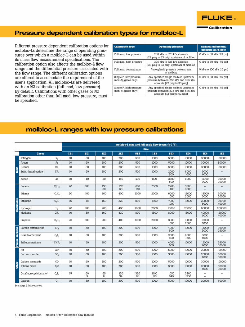
Different pressure dependent calibration options for molbloc-Ls determine the range of operating pres-sures over which a molbloc-L can be used within its mass flow measurement specifications. The calibration option also affects the molbloc-L flow range and the differential pressure associated with the flow range. The different calibration options are offered to accomodate the requirement of the user’s application. All molbloc-Ls are delivered with an N2 calibration (full mod, low pressure) by default. Calibrations with other gases or N2 calibration other than full mod, low pressure, must be specified.
Pressure dependent calibration types for molbloc-L
molbloc-L ranges with low pressure calibrations
Calibration type Operating pressure Nominal differential pressure at FS flow
Full mod, low pressure 250 kPa to 325 kPa absolute (22 psig to 33 psig) upstream of molbloc
0 kPa to 50 kPa (7.5 psi)
Full mod, high pressure 325 kPa to 525 kPa absolute (33 psig to 62 psig) upstream of molbloc
0 kPa to 50 kPa (7.5 psi)
Full mod, downstream Atmospheric pressure downstream of molbloc
0 kPa to 100 kPa (15 psi)
Single P, low pressure (non-N2 gases only)
Any specified single molbloc upstream pressure between 250 kPa and 325 kPa
absolute (22 psig to 33 psig)
0 kPa to 50 kPa (7.5 psi)
Single P, high pressure (non-N2 gases only)
Any specified single molbloc upstream pressure between 325 kPa and 525 kPa
absolute (33 psig to 62 psig)
0 kPa to 50 kPa (7.5 psi)

5 Fluke Corporation molbox RFM™ Reference flow monitor
molbloc-L size and full scale flow (sccm @ 0 °C)
Size
Gases 1E1 5E1 1E2 2E2 5E2 1E3 5E3 1E4 3E4 1E5
Iner
t
Nitrogen N2 20 100 200 400 1000 2000 10000 20000 40000 N/A7500
Argon Ar 20 100 200 400 1000 2000 10000 17000 35000 N/A6000
Helium He 20 100 200 400 1000 2000 10000 20000 65000 N/A
Sulfur hexafluoride SF6 25 100 120 250 600 2000 2000 6200 — N/A15 30 50 150 300 1400 2800 — N/A
Xenon Xe 20 100 150 350 650 1700 3350 11000 11000 N/A950 1900 5700
Flam
mab
le
Butane2 C4H10 N/A N/A N/A N/A N/A N/A N/A N/A N/A N/A
Ethane C2H6 40 200 350 700 1800 4000 6000 20000 20000 N/A50 100 200 2300 4500 13800 N/A
Ethylene C2H4 40 200 350 700 1800 4000 7000 22000 22000 N/A2000 4000 12700
Hydrogen H2 40 200 400 900 2000 4500 22000 45000 130000 N/A
Methane CH4 35 175 350 700 1700 3500 13000 33000 42000 N/A2000 12000
Propane C3H8 50 200 200 400 1000 3500 3500 11000 — N/A25 50 100 250 500 2600 5400 —
Fluo
ro-c
arb
ons Carbon tetrafluoride CF4 20 100 200 400 1000 2000 3700 12000 12000 N/A
1200 2400 7300
Hexafluoroethene C2F6 25 100 120 250 600 2000 1800 6000 — N/A15 30 50 150 300 1500 3000 —
Trifluoromethane CHF3 25 125 240 450 1200 2500 4000 12000 12000 N/A30 60 150 1500 3000 8800
Oth
er
Air Air 20 100 200 400 1000 2000 10000 20000 40000 N/A7200
Carbon dioxide CO2 25 125 250 500 1250 2500 6600 20000 40000 N/A1400 2500 8800
Carbon monoxide CO 20 100 200 400 1000 2000 10000 20000 40000 N/A7500
Nitrous oxide N2O 25 125 250 500 1250 2500 11000 20000 20000 N/A1500 3000 9000
Octafluorocyclobutane2 C4F8 N/A N/A N/A N/A N/A N/A N/A N/A N/A N/A
Oxygen O2 20 100 200 400 1000 2000 10000 20000 40000 N/A6500
A bold value indicates that the maximum flow is limited by the maximum Reynolds number value of 1200 which is reached before the normal differential pressure range is reached. In that case, the second value gives the minimum flow for which measurement uncertainty (accuracy) is equal to the nominal uncertainty specification. Divide the second value by 10 when using molbox RFM microrange option.
Where there is no value in the field (–), this indicates that the maximum Reynolds number is reached before the differential pressure reaches 5 kPa (1 kPa in the case of the 1E5 molbloc), therefore calibration with that gas is not useful.
1 Due to low vapor pressure, only downstream calibration type is available.
2 The operating pressure range is greater than the vapor pressure value for this gas.
molbloc-L ranges with high pressure calibrations

Fluke Calibration PO Box 9090, Everett, WA 98206 U.S.A.
Fluke Europe B.V. PO Box 1186, 5602 BD Eindhoven, The Netherlands
For more information call: In the U.S.A. (800) 443-5853 or Fax (425) 446-5116 In Europe/M-East/Africa +31 (0) 40 2675 200 or Fax +31 (0) 40 2675 222 In Canada (800)-36-FLUKE or Fax (905) 890-6866 From other countries +1 (425) 446-5500 or Fax +1 (425) 446-5116 Web access: http://www.fluke.com
©2010 Fluke Corporation. Specifications subject to change without notice. Printed in U.S.A. 6/2010 3191934B B-EN-N
Modification of this document is not permitted without written permission from Fluke Corporation.
Fluke. Keeping your world up and running.®
6 Fluke Corporation molbox RFM™ Reference flow monitor
Ordering information
Model molbox RFM Reference flow monitor
Includes Users manual, calibration certificate, power cord, (2) molbox RFM to molbloc pressure lines, (1) molbox RFM to molbloc data line, (2) Straight through pressure quick connectors
Options RFM 02 Microrange
Accessories RFM-RMK (401465) Rack mount kitmfc-CB Analog MFC interface system (see mfc-CB brochure)molstic molbloc mounting systems (see molstic brochure)COMPASS® for molbox for Windows (401211) Calibration software
Power requirements 85 V ac to 264 V ac, 47 Hz to 440 Hz, 18 VA max consumption
Operating temperature range 15 °C to 35 °C (59 °F to 95 °F)
Storage temperature range -20 °C to 70 °C (-4 °F to 158 °F)
Vibration Meets MIL-T-28800D
Weight 2.55 kg (5.6 lb) max
Dimensions (H x W x D) 8 cm x 22.5 cm x 20 cm (3.1 in x 8.9 in x 7.9 in) approx.
Microprocessor Motorola 68302, 16 MHz
Communication ports RS-232 (COM1), RS-232 (COM2), IEEE-488
Reference pressure transducers (RPTs)
Standard 2 x 600 kPa (87 psia) piezoresistive silicon
Microrange Option 12.5 kPa (1.8 psid) piezoresistive silicon
Gases supported for molbloc-L Nitrogen (N2), Air, Argon (Ar), Carbon Monoxide (CO), Helium (He), Oxygen (O2), Carbon Dioxide (CO2), Carbon Tetrafluoride (CF4), Ethane (C2H6), Ethylene (C2H4), Fluoroform (CHF3), Hexafluoroethane (C2F6), Hydrogen (H2), Methane (CH4), Nitrous Oxide (N2O), Propane (C3H8), Sulfur Hexafluoride (SF6)
for molbloc-S N2, He, Ar, H2, O2, CH4, Air, N2O, SF6, CO2, CO
Pressure connections Quick connectors equivalent to Swagelok QM Series (-QM2-B200)
Pressure limits Maximum working pressure: 600 kPa absolute (87 psia)
Flow ranges Covers the flow range of 1 sccm to
100 slm with molbloc-L, and up to 5000 slm with molbloc-S
Flow measurement uncertainty ± 0.5 % of reading
CE conformance Available. Must be specified
General specifications