monitoring and checking standard iec 61850 sobrevii...
TRANSCRIPT
Noviembre 2 ,7 28 29yMedel l ín ColombiaMedel l ín Colombia
VIIS
impo
sio
Inte
rnac
iona
lsob
reVI
I20
13
Abstract— Recently in the context of Smart Grid, it has
worked to IEC 61850 standard, which application is getting more
common. This standard defines an initial step towards a smarter
grid. IEC 61850 "Communication networks and systems in
substations", will bring open and interoperable systems for the
automation domain substations. The development of the
standard has generated requirements for manufacturers of
devices compatible with it. These manufacturers are forced to
have their equipment meets certain requirements regarding the
functionality of the devices. The aim of this work is to specify the
standard techniques for the development of conformance testing.
The idea is to make a comparison between the concepts and
guidelines that define the standard IEC 61850 for the
development of conformance tests, compared to other guidelines
and methodologies established in the electricity sector for
compliance testing of different industrial communication
protocols.
Key Words— IEC 61850, Conformance Testing, Substation
automation, SCL, IED, LN, MMS, ACSI.
I. INTRODUCTION
he tests developed in devices in order to evaluate how the
manufacturer implemented the standard features and
capabilities of the IED IEC 61850 are covered by IEC 61850-
10 "Conformance Testing". This defines some of the methods
and test cases that must be applied to equipment in order to
achieve compliance with IEC 61850. But compliance does not
mean that devices must to fulfill all the functions and services
that are specified in the standard. Compliance means that the
device meets a limited way some of the functions provided by
the standard.
The aim of this work is to specify the standard techniques
for the development of conformance testing. The idea is to
make a comparison between the concepts and guidelines that
define the standard IEC 61850, with respect to other
guidelines and methodologies established in the electricity
sector, without losing sight of the concepts and tests
developed by international laboratories.
The use of these techniques improve the ability to test
system integration to easily link Intelligent Electronic Devices
(IED), operate IED correctly and properly support different
applications in SAS (Substation Automation System).
The aim of conformance testing is to generate security to
the system integrators in order to reduce operating errors and
problems that may arise in the field.
The tests presented in this article served as the basis for the
development of a project that create a testing laboratory at the
Faculty of Mines of the National University from Colombia
with support from CODENSA SA ESP
II. CONTEXT OF THE COMMUNICATIONS SECTOR IN THE
ELECTRICITY SECTOR
Major advances in communications technology have made
that communications technologies are developed for the power
sector which is expanding rapidly.
In the early, communications systems in substations were
unsophisticated. It had measuring and protection analog
devices and electromechanical relays. It was required much
wiring for the equipment signals.
The next breakthrough was the development of
communication protocols by each relay manufacturer; they
developed their own protocols to communicate their own
devices, which lead to clients using specific applications from
a specific manufacturer.
Currently with the development of IEC 61850 that situation
could change, because the standard tends to standardize
equipment manufacturers. The main objective of the standard
is the interoperability, which means that equipment from
different manufacturers can communicate among them, and
perform common tasks.
III. PROPOSAL FOR THE TESTING METHODOLOGY
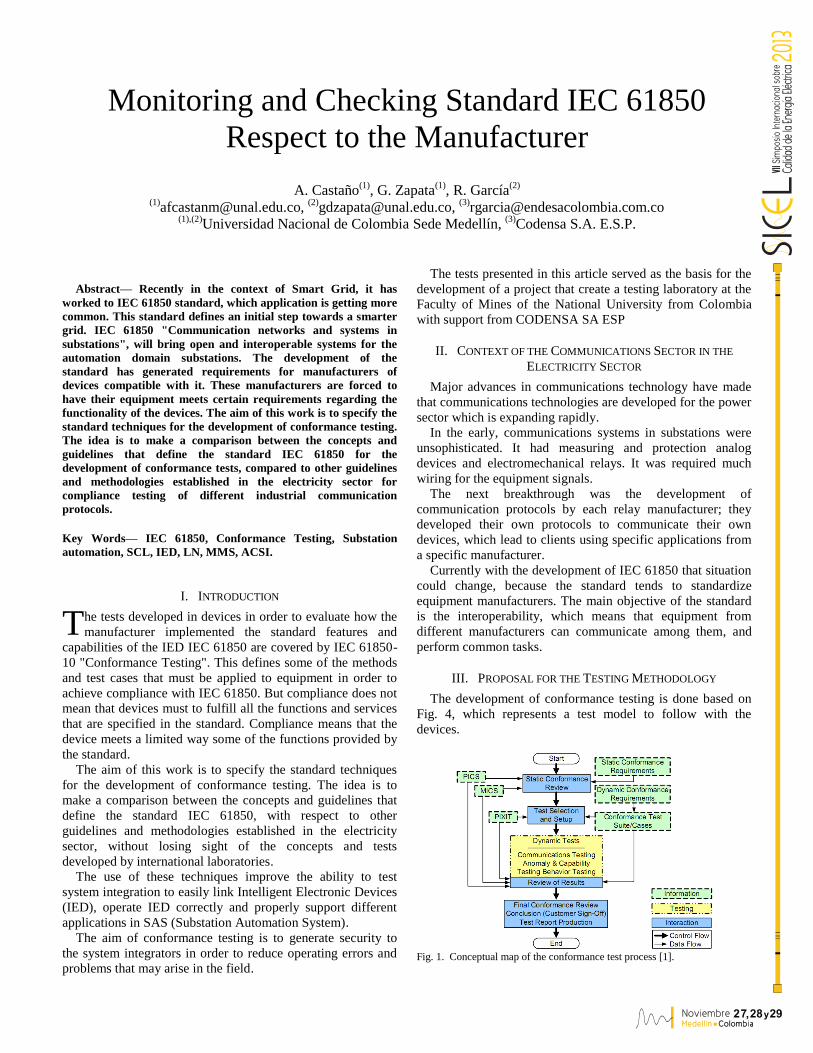
The development of conformance testing is done based on
Fig. 4, which represents a test model to follow with the
devices.
Fig. 1. Conceptual map of the conformance test process [1].
Monitoring and Checking Standard IEC 61850
Respect to the Manufacturer
A. Castaño(1)
, G. Zapata(1)
, R. García(2)
(1)
[email protected], (2)
[email protected], (3)
[email protected] (1),(2)
Universidad Nacional de Colombia Sede Medellín, (3)
Codensa S.A. E.S.P.
T
Noviembre 2 ,7 28 29yMedel l ín ColombiaMedel l ín Colombia
VIIS
impo
sio
Inte
rnac
iona
lsob
reVI
I20
13
The following steps are intended to propose a methodology
for making conformity test an IED with IEC 61850.
Step 0 (Test Environment)
This test environment must contain the following elements
to initiate any compliance testing:
- DUT (Device Under Test)
- Test Simulators (Software)
- Test Analyzers (Software)
- Configuration Files (ICD, SCD)
- Ethernet Cords
- Switch
Fig. 2. Test Architecture [11].
It must implement the test architecture of Fig. 2 to continue
with step 1.
Step 1 (Documentation)
After having the test architecture shown in Figure 2, it is
proceed to gather the necessary documentation of the device
under test:
- Model Implementation Conformance Statement (MICS).
- Protocol Implementation Conformance Statement (PICS).
- Protocol Implementation eXtra Information for Testing
(PIXIT).
- File with .ICD extension (IED Capability Description).
- File with .SCD extension (Substation Configuration
Description).
- Instruction manuals detailing IED Hardware/Software
versions.
Step 2 (Sections of the SCL file)
This step is performed in order to verify that the SCL file
sections are consistent with the provisions of the IEC 61850-6.
SCL Sections:
- Header (identifies the configuration file).
- Substation (identifies connections and electrical
functions).
- Communications (identifies addresses and subnets)
- IED (identifies device functions and settings).
- Data Type Templates (used to construct the other
sections).
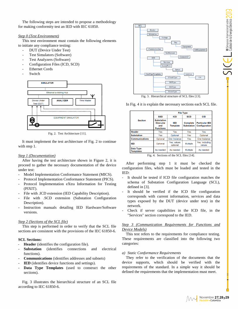
Fig. 3 illustrates the hierarchical structure of an SCL file
according to IEC 61850-6.
Fig. 3. Hierarchical structure of SCL files [13].
In Fig. 4 it is explain the necessary sections each SCL file.
Fig. 4. Sections of the SCL files [14].
After performing step 1 it must be checked the
configuration files, which must be loaded and tested in the
IED:
- It should be tested if ICD file configuration matches the
schema of Substation Configuration Language (SCL),
defined in [3].
- It should be verified if the ICD file configuration
corresponds with current information, services and data
types exposed by the DUT (device under test) in the
network.
- Check if server capabilities in the ICD file, in the
"Services" section correspond to the IED.
Step 3 (Communication Requirements for Functions and
Device Models)
This test refers to the requirements for compliance testing.
These requirements are classified into the following two
categories:
a) Static Conformance Requirements
They refer to the verification of the documents that the
device supports, which should be verified with the
requirements of the standard. In a simple way it should be
defined the requirements that the implementation must meet.
Noviembre 2 ,7 28 29yMedel l ín ColombiaMedel l ín Colombia
VIIS
impo
sio
Inte
rnac
iona
lsob
reVI
I20
13
b) Dynamic Conformance Requirements
They refer to the real check in the device. Here it is verified
that the device complies with the characteristics that were
exposed in the documentation. In a simple way it is defined
the requirements to be met by the protocol used in a particular
implementation.
Step 4 (Verification of the data model [6],[7])
In this step it is performed the verifying of the data
implementation given by the manufacturer in the device:
- Check for required objects for each Logical Node
(Presence = M, Optional = O y Conditional = C).
- Check which conditional objects are present and are
correct.
- Check conditional objects that are not present and are not
right for each logical node.
- Check the data types of all objects of each Logical Node
(LN).
- Check if the order of the data objects within the logical
node types match the standard [7].
- Check if the order of the attributes of the data within the
data objects types match the standard in [6] (Common
Data Classes).
- Check if the manufacturer specifies extensions of the
implemented data models in accordance with extension
rules in [7] Annex A. (only when the extension is
implemented).
Step 5 (Mapping of the ACSI models and services)
In this step it is defined the communication requirements
for IEC 61850 products and it is evaluated the necessary
communication skills to support the SAS (Substation
Automation System) environment.
It is valid to clarify that the letter „A‟ in ACSI means
"abstract", and that the test of the services is performed
without explicitly invoking ACSI service requests by name.
The ACSI test is done through the MMS services which have
its equivalent in ACSI.
IED manufacturers give the Protocol Implementation
Conformance Statement (PICS) document, which contain a
series of tables which identify the communication features that
may or may not be implemented on a device.
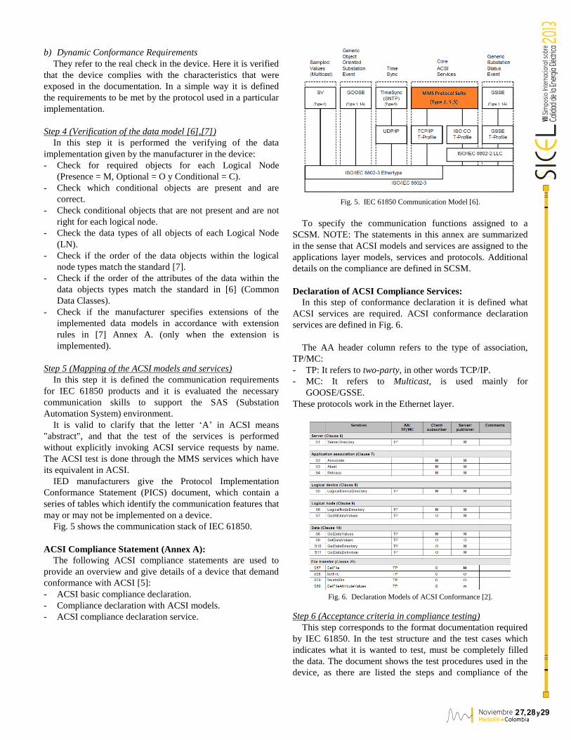
Fig. 5 shows the communication stack of IEC 61850.
ACSI Compliance Statement (Annex A):
The following ACSI compliance statements are used to
provide an overview and give details of a device that demand
conformance with ACSI [5]:
- ACSI basic compliance declaration.
- Compliance declaration with ACSI models.
- ACSI compliance declaration service.
Fig. 5. IEC 61850 Communication Model [6].
To specify the communication functions assigned to a
SCSM. NOTE: The statements in this annex are summarized
in the sense that ACSI models and services are assigned to the
applications layer models, services and protocols. Additional
details on the compliance are defined in SCSM.
Declaration of ACSI Compliance Services:
In this step of conformance declaration it is defined what
ACSI services are required. ACSI conformance declaration
services are defined in Fig. 6.
The AA header column refers to the type of association,
TP/MC:
- TP: It refers to two-party, in other words TCP/IP.
- MC: It refers to Multicast, is used mainly for
GOOSE/GSSE.
These protocols work in the Ethernet layer.
Fig. 6. Declaration Models of ACSI Conformance [2].
Step 6 (Acceptance criteria in compliance testing)
This step corresponds to the format documentation required
by IEC 61850. In the test structure and the test cases which
indicates what it is wanted to test, must be completely filled
the data. The document shows the test procedures used in the
device, as there are listed the steps and compliance of the
Noviembre 2 ,7 28 29yMedel l ín ColombiaMedel l ín Colombia
VIIS
impo
sio
Inte
rnac
iona
lsob
reVI
I20
13
standard parts involved, test results, description of the steps,
problems and observations during the test.
Fig. 7. Format of test procedures [1].
IV. APPLICATION OF THE METHODOLOGY IN A STUDY CASE
The next development is the application of the proposed
methodology to the IED REL 670 ®, where is specified and
showed the execution of the steps in the IED.
Step 0 (Test Environment)
The device under test is the ABB REL 670 ®. Fig. 8 shows
the architecture used for conducting the tests:
Fig. 8. Test Architecture [11].
Step 1 (Documentation)
The following documentation was supplied by ABB:
- 1MRK117-792, rev G; IED 670, version 1.2, MICS.
- 1MRG000835, rev C; IED 670, version 1.2, PICS.
- 1MRG000707, rev C; IED 670, version 1.2, PIXIT.
- Files downloaded from the current configuration of the
relay.
- File_Rel_670.icd.
- File_Rel_670.scd.
Step 2 (Configuration Files)
It should be tested if the configuration of ICD file matches
the schema of Substation Configuration Language (SCL),
defined in [3].
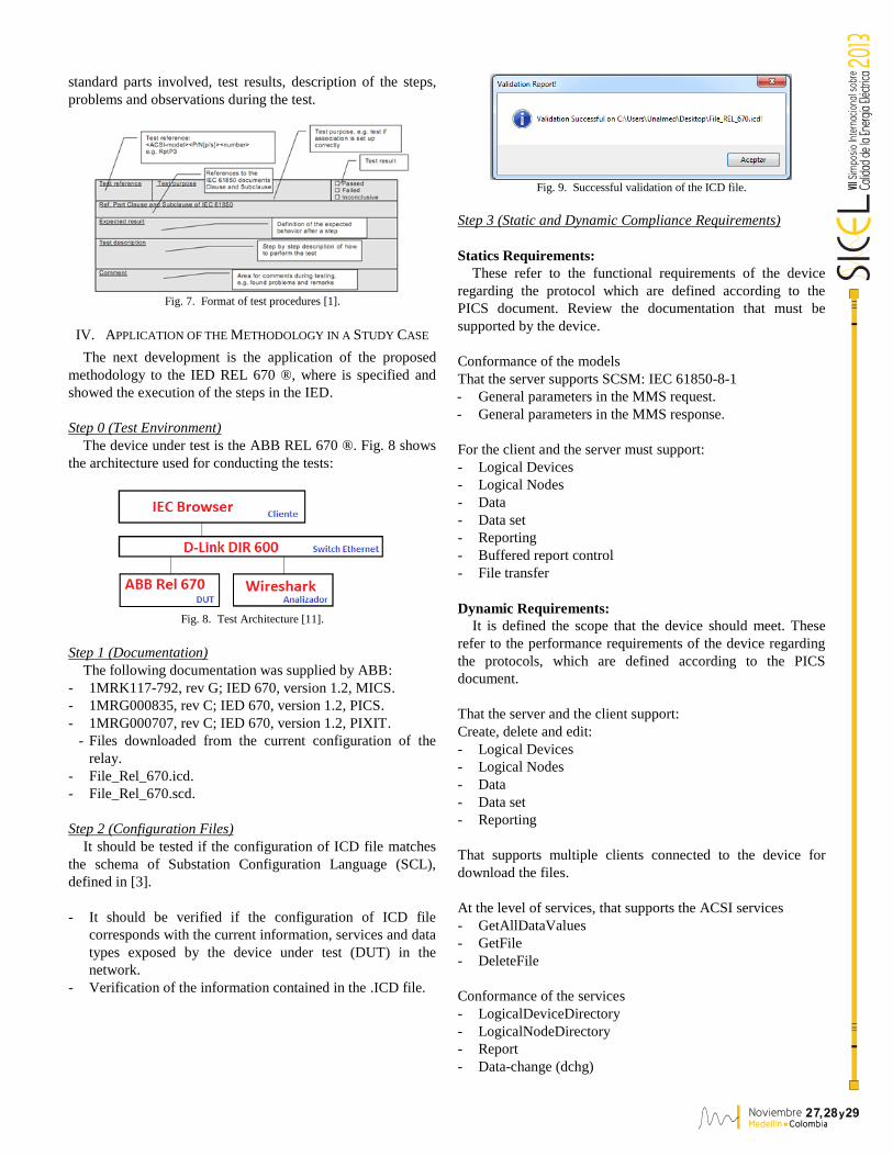
- It should be verified if the configuration of ICD file
corresponds with the current information, services and data
types exposed by the device under test (DUT) in the
network.
- Verification of the information contained in the .ICD file.
Fig. 9. Successful validation of the ICD file.
Step 3 (Static and Dynamic Compliance Requirements)
Statics Requirements:
These refer to the functional requirements of the device
regarding the protocol which are defined according to the
PICS document. Review the documentation that must be
supported by the device.
Conformance of the models
That the server supports SCSM: IEC 61850-8-1
- General parameters in the MMS request.
- General parameters in the MMS response.
For the client and the server must support:
- Logical Devices
- Logical Nodes
- Data
- Data set
- Reporting
- Buffered report control
- File transfer
Dynamic Requirements:
It is defined the scope that the device should meet. These
refer to the performance requirements of the device regarding
the protocols, which are defined according to the PICS
document.
That the server and the client support:
Create, delete and edit:
- Logical Devices
- Logical Nodes
- Data
- Data set
- Reporting
That supports multiple clients connected to the device for
download the files.
At the level of services, that supports the ACSI services
- GetAllDataValues
- GetFile
- DeleteFile
Conformance of the services
- LogicalDeviceDirectory
- LogicalNodeDirectory
- Report
- Data-change (dchg)
Noviembre 2 ,7 28 29yMedel l ín ColombiaMedel l ín Colombia
VIIS
impo
sio
Inte
rnac
iona
lsob
reVI
I20
13
- File transfer
- GetFile
- DeleteFile
Step 4 (Verification of the data models)
In this verification is taken into account first the devices and
logical nodes present in the IED ABB REL 670 ®.
For the logical devices (LD) present int the device, it is
carried the following conformance testing methodology
concerning to model validation of data contained in the IED:
- Check the presence of required objects for each Logical
Node (Presence = M, Optional = O y Conditional = C).
- Check the conditional objects that are not present and are
not right for each logical node.
- Check that the order of the data objects within the logical
node types match the standard [2].
In the verification of the data model is take into account the
MICS document (Model Implementation Conformance
Statement). In this document there is a description of the types
of logical nodes and data contained on the device. Along with
this document it should be verified the ICD file, which
displays the current settings related to the data model
contained in the kit.
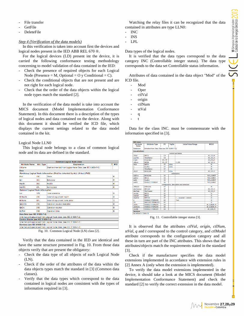
Logical Node LLN0
This logical node belongs to a class of common logical
node and its data are defined in the standard.
Fig. 10. Common Logical Node (LN) class [2].
Verify that the data contained in the IED are identical and
have the same structure presented in Fig. 10. From those data
objects verify that are present the obligatory:
- Check the data type of all objects of each Logical Node
(LN).
- Check if the order of the attributes of the data within the
data objects types match the standard in [3] (Common data
classes).
- Verify that the data types which correspond to the data
contained in logical nodes are consistent with the types of
information required in [3].
Watching the relay files it can be recognized that the data
contained in attributes are type LLN0:
- INC
- INS
- LPL
Data types of the logical nodes.
It is verified that the data types correspond to the data
category INC (Controllable integer status). The data type
corresponds to the data set Controllable status information.
Attributes of data contained in the data object "Mod" of the
ICD file.
- Mod
- Oper
- ctlVal
- origin
- ctlNum
- stVal
- q
- t
Data for the class INC. must be commensurate with the
information specified in [3].
Fig. 11. Controllable integer status [3].
It is observed that the attributes ctlVal, origin, ctlNum,
stVal, q and t correspond to the control category, and ctlModel
attribute corresponds to the configuration category and all
these in turn are part of the INC attributes. This shows that the
attributes/objects match the requirements stated in the standard
[3].
Check if the manufacturer specifies the data model
extensions implemented in accordance with extension rules in
[2] Annex A (only when the extension is implemented).
To verify the data model extensions implemented in the
device, it should take a look at the MICS document (Model
Implementation Conformance Statement) and check the
standard [2] to verify the correct extension in the data model.
Noviembre 2 ,7 28 29yMedel l ín ColombiaMedel l ín Colombia
VIIS
impo
sio
Inte
rnac
iona
lsob
reVI
I20
13
Extension Rules of Logical Nodes and Data.
The Extension Rules for a Logical Node are [2]:
- If there is any logical node class that fits the function to be
modeled, an instance of the logical node will be used with
all mandatory data (M).
- If there are specialized versions of this function with the
same basic data (e.g. ground, phase, zone A, zone B etc.),
different instances of this class of logical node will be
used.
- Other extensions are not allowed in the field of substation
automation.
Fig. 12 shows an example for time overcurrent.
Fig. 12. Extension of functions of a Logical Node (LN) Example [2].
Step 5 (Mapping of the ACSI models and services)
This step is the evaluation of the performance of services by
the IED. Here it is verified that the device supports the
execution of a specific service and besides that make capturing
and analysis with regard to IEC 61850-7-2.
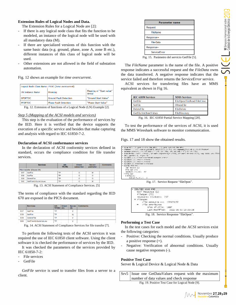
Declaration of ACSI conformance services
In the declaration of ACSI conformity services defined in
standard, occurs the compliance condition for file transfer
services.
Fig. 13. ACSI Statement of Compliance Services. [5]
The terms of compliance with the standard regarding the IED
670 are exposed in the PICS document.
Fig. 14. ACSI Statement of Compliance Services for file transfer [7].
To perform the following tests of the ACSI services it was
required the use of IEC 61850 client software. Using the client
software it is checked the performance of services by the IED.
It was checked the parameters of the services provided by
IEC 61850-7-2:
- File services
- GetFile
GetFile service is used to transfer files from a server to a
client.
Fig. 15. Parámetro del servicio GetFile [5].
The FileName parameter is the name of the file. A positive
response indicates a successful request and the FileData owns
the data transferred. A negative response indicates that the
service failed and therefore returns the ServiceError service.
ACSI services for transferring files have an MMS
equivalent as shown in Fig 16.
Fig. 16. IEC 61850 Partial Service Mapping [20].
To test the performance of the services of ACSI, it is used
the MMS Wireshark software to monitor communication.
Figs. 17 and 18 show the obtained results.
Fig. 17. Service Request “fileOpen”.
Fig. 18. Service Response “fileOpen”.
Performing a Test Case
In the test cases for each model and the ACSI services exist
the following categories:
- Positive: Checking the normal conditions. Usually produce
a positive response (+).
- Negative: Verification of abnormal conditions. Usually
cause negative responses (-).
Positive Test Case
Server & Logical Device & Logical Node & Data
Srv5 Issue one GetDataValues request with the maximum
number of data values and check response Fig. 19. Positive Test Case for Logical Node [9].
Noviembre 2 ,7 28 29yMedel l ín ColombiaMedel l ín Colombia
VIIS
impo
sio
Inte
rnac
iona
lsob
reVI
I20
13
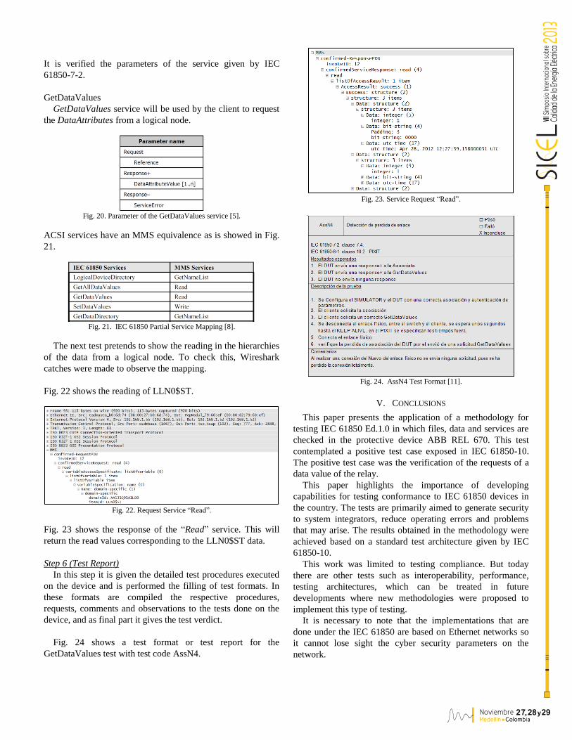
It is verified the parameters of the service given by IEC
61850-7-2.
GetDataValues
GetDataValues service will be used by the client to request
the DataAttributes from a logical node.
Fig. 20. Parameter of the GetDataValues service [5].
ACSI services have an MMS equivalence as is showed in Fig.
21.
Fig. 21. IEC 61850 Partial Service Mapping [8].
The next test pretends to show the reading in the hierarchies
of the data from a logical node. To check this, Wireshark
catches were made to observe the mapping.
Fig. 22 shows the reading of LLN0$ST.
Fig. 22. Request Service “Read”.
Fig. 23 shows the response of the “Read” service. This will
return the read values corresponding to the LLN0$ST data.
Step 6 (Test Report)
In this step it is given the detailed test procedures executed
on the device and is performed the filling of test formats. In
these formats are compiled the respective procedures,
requests, comments and observations to the tests done on the
device, and as final part it gives the test verdict.
Fig. 24 shows a test format or test report for the
GetDataValues test with test code AssN4.
Fig. 23. Service Request “Read”.
Fig. 24. AssN4 Test Format [11].
V. CONCLUSIONS
This paper presents the application of a methodology for
testing IEC 61850 Ed.1.0 in which files, data and services are
checked in the protective device ABB REL 670. This test
contemplated a positive test case exposed in IEC 61850-10.
The positive test case was the verification of the requests of a
data value of the relay.
This paper highlights the importance of developing
capabilities for testing conformance to IEC 61850 devices in
the country. The tests are primarily aimed to generate security
to system integrators, reduce operating errors and problems
that may arise. The results obtained in the methodology were
achieved based on a standard test architecture given by IEC
61850-10.
This work was limited to testing compliance. But today
there are other tests such as interoperability, performance,
testing architectures, which can be treated in future
developments where new methodologies were proposed to
implement this type of testing.
It is necessary to note that the implementations that are
done under the IEC 61850 are based on Ethernet networks so
it cannot lose sight the cyber security parameters on the
network.
Noviembre 2 ,7 28 29yMedel l ín ColombiaMedel l ín Colombia
VIIS
impo
sio
Inte
rnac
iona
lsob
reVI
I20
13
ACKNOWLEDGMENTS
The authors express publicly their gratitude to CODENSA
S.A. ESP for their support in the development of this work and
the current assembly of the Laboratory. Today, at the Faculty
of Mines there are devices available for test the architectures
present in some power substations. This will allow that the lab
in the future to be a leader in South America in this area. Fig.
25 shows the equipment currently available.
Fig. 25. Available devices in the Laboratory of the Faculty of Mines.
REFERENCES
[1] International Standard IEC 61850, Communication networks and
systems in substations, Part 4: System and project management. 2002.
[2] International Standard IEC 61850, Communication networks and systems in substations, Part 5: Communication requirements for
functions and device models. 2003.
[3] International Standard IEC 61850, Communication networks and systems in substations, Part 6: Configuration description language for
communication in electrical substations related to IEDs. 2004.
[4] International Standard IEC 61850, Communication networks and
systems in substations, Part 7-1: Basic communication structure for
substation and feeder equipment –Principles and models. 2003.
[5] International Standard IEC 61850, Communication networks and systems in substations, Part 7-2: Basic communication structure for
substation and feeder equipment – Abstract communication service interface (ACSI). 2003.
[6] International Standard IEC 61850, Communication networks and
systems in substations, Part 7-3: Basic communication structure for
substation and feeder equipment –Common data classes. 2003.
[7] International Standard IEC 61850, Communication networks and
systems in substations, Part 7-4: Basic communication structure for
substation and feeder equipment – Compatible logical node classes and data classes. 2003.
[8] International Standard IEC 61850, Communication networks and
systems in substations, Part 8-1: Specific Communication Service Mapping (SCSM) –Mappings to MMS (ISO 9506-1 and ISO 9506-2)
and to ISO/IEC 8802-3. 2004.
[9] International Standard IEC 61850, Communication networks and systems in substations, Part 9-1: Specific Communication Service
Mapping (SCSM) –Sampled values over serial unidirectional multidrop
point to point link. 2003. [10] International Standard IEC 61850, Communication networks and
systems in substations, Part 9-2: Specific Communication Service
Mapping (SCSM) – Sampled values over ISO/IEC 8802-3. 2004. [11] International Standard IEC 61850, Communication networks and
systems in substations, Part 10: Conformance testing. 2005.
[12] Colombia Inteligente, Marco Estratégico y Propuesta Proyecto Nacional de Redes Inteligentes en Colombia. 2011.
[13] Zhihong Huo, Limin Zhang, Zhixue zhang, “Research on Graphics
Model Design for IEC61850 SCL Visual Configuration”, IEEE Pacific-Asia Workshop on Computational Intelligence and Industrial
Application. 2008.
[14] International Electrotechnical Commission (IEC), Substation Configuration Language, Summary, August 2006.
[15] Richard Schimmel (KEMA), Conformance Test Procedures for Server
Devices with IEC 61850-8-1 interface, Revision 2.3, May 2011. [16] UCA® International Users Group, IEC 61850 Conformance Testing.
[17] Hubert Kirrmann (ABB) ,Introduction to the IEC 61850, 2012.
[18] 1MRK 506 279-BES, rev A, Protección de distancia de línea REL670 Configuración abierta, Version 1,1. ABB, Octubre de 2010.
[19] 1MRK117-792, rev G, ABB 670 Series, IEC 61850 MICS (Model
Implementation Conformance Statement), Versión 1.2, August, 2010. [20] R. E. Mackiewicz, “Overview of IEC 61850 and Benefits”, 2006.
[21] 1MRG000707, rev C, ABB 670 Series, PIXIT Protocol Extra
Information, Version 1.2, August, 2010. [22] 1MRG000835, rev C, ABB 670 Series, PICS Protocol Implementation
Conformance Statement, Version 1.2, August, 2010. [23] Substations Committee and the Power Systems Relaying Committee,
IEEE Standard for electrical power system device function numbers,
acronyms, and contact designations, October, 2008.