monitoring and control system implementation
TRANSCRIPT

MoCoMonitoring and Control SystemImplementation
Open Source Monitoring and ControlHow to Configure a Working System, Start to Finish
POB 992, La Veta, CO [email protected] 877-360-2582 Draft Version 2010-06-20Software Version 0.54© MoCoWorks 2010
MoCoWorks Reed White
MoCo Monitoring and Control System Implementation - © MoCoWorks 2010 - 877-360-2582 - 2010-06-20 - 1 of 116

Contents1. Introduction
1.1 What is MoCo?1.2 System Design Goals1.3 Design Strategies and Tactics
2. Small System Quick-Start
2.1 Software Installation Overview2.1 Installation on Linux or Unix2.2 Installation on Apple Mac OS-X2.3 Installation on Windows2.4 SQLite Notes2.5 Hardware Transducers and I/O Interface Setup2.6 Using FormEdit2.7 Initial MoCo Startup2.8 After Initial Startup
3. Under the Hood
3.1 Data Processing3.2 System Considerations
4. Changing System Parameters with mocom
4.1 What mocom Can Do4.2 Operation
5. Points: Input, Output, Calc, and Time
5.1 Points in General5.2 Points Scheduling5.3 Input Points5.4 Conventional Output Points5.5 Outputting Points and Their Values to a File5.6 Time Points
5.6.1 Time Clock – time_clock5.6.2 [ ] Pulse-width Modulated Pulser – time_PWM_pulser5.6.3 [ ] PID Loop – time_PID_loop
5.7 Calculation Points5.7.1 Common Functions – calc_functions5.7.2 Math Expressions – calc_expression
MoCo Monitoring and Control System Implementation - © MoCoWorks 2010 - 877-360-2582 - 2010-06-20 - 2 of 116

5.7.3 Ladder Logic – calc_ladder_logic5.8 Counters and Stopwatch Timers5.9 Creating Scenes
6. Alarms
6.1 Alarms Overview6.2 Confguring Alarms6.3 Handling Alarms6.4 Alarms Triggering Shell Commands
7. Reports
7.1 Reports Overview7.2 Status Reports7.3 History Reports7.4 Shell Scripts for Common Reports7.5 Graphic Web Status Reports7.6 Custom Database Reports
8. [ ] Programming State Machine Points
9. Example Task Snippets
9.1 Turn On Multiple Lights with Distributed Switches9.2 Duty Cycle Calculation9.3 Door Opening Counter9.4 Scenes and Sequencing
10. Software Maintenance
10.1 Backups10.2 Log FIle10.3 Database10.4 Shell Scripts
11. [ ] Basic Transducer Electronics
12. [ ] Example Projects
13. [ ] Creating a Web-based User Interface
14. [ ] Confguring an Enterprise-level Distributed Network
15. [ ] Writing a Custom Perl Snippet
16. [ ] Writing a Driver
MoCo Monitoring and Control System Implementation - © MoCoWorks 2010 - 877-360-2582 - 2010-06-20 - 3 of 116

Appendix A – Parameters
A.1 System-wide Parameters in moco.ini FileA.2 Point Parameters in .cfg FilesA.3 Report Parameters in .rpt FilesA.4 User Parameters in .usr Files
Appendix B – Sample .cfg Files
B.1 Input .cfg File SampleB.2 Time Clock .cfg File SampleB.3 Calculation Expression .cfg File SampleB.4 Calculation Ladder Logic .cfg File SampleB.5 Input .cfg File Sample
Appendix C – Drivers
Appendix D – I/O Bridges
D.1 NA7NetD.2 OM-ServerD.3 WebControl, EDS and PLCD.4 ISY-99iD.5 EMACSYS
Appendix E – Troubleshooting
E.1 GeneralE.2 MoCo SoftwareE.3 NetworkingE.4 1-wireE.5 X10 and Insteon
Appendix F – Transducer Wiring Details
F.1 Pitfalls To AvoidF.2 RJ-11/12 4-wire Telephone-style PlugF.3 RH-11/12 6-wire Telephone-style PlugF.4 6-wire to 4-wire to 2-wireF.5 RJ-45 8-wire Ethernet Plug
MoCo Monitoring and Control System Implementation - © MoCoWorks 2010 - 877-360-2582 - 2010-06-20 - 4 of 116

1. Introduction
Mission Statement: To provide an open source, network-centric, industrial strength monitoring and control system that is scalable from small projects to a world-wide network, which will run on all major platforms and use low-cost interface hardware.
NOTE: We do appreciate your suggestions for this document and the MoCo software.
1.1 What is MoCo?
Moco is a scaleable software system for monitoring and control of analog and digital I/O points. It is equally at home on a single computer or multiple computers networked world-wide. The computers' operating systems may be Linux, Unix, Mac, or Windows.
MoCo is built at MoCoWorks upon no-cost open source software, and it works with affordable I/O hardware. Its scalable architecture is suited for a wide range of applications, ranging from home automation system, energy management projects, irrigation systems, lighting control, microbrewery process control, to a variety of distributed applications in a manufacturing plant – in other words, for industrial SCADA (Supervisory Control And Data Acquisition) systems.
A high priority has been given to building upon a solid foundation: stable, bullet-proof software foundation (such as perl), with an architecture that enables painless upgrades and backups. MoCo can be upgraded by replacing text-based perl programs – no compilation required. Configuration data can be backed up simply by saving a group of human-readable text files.
MoCo, at its present stage of development, is a functional monitoring and control engine. While it does provide versatile status and history reports, users who want customized color graphical reports will need to do this work themselves. MoCo architecture enables user interface embellishments to be added with traditional unix/linux techniques – and without the need to modify MoCo software.
1.2 System Design Goals
MoCo's designer gained his knowledge and beliefs about monitoring and control system design from experiences in sawmill automation, IC manufacturing automation, and from corporate building automation. After retiring from the corporate world, he designed MoCo, a system that strives to meet the following objectives:
MoCo Monitoring and Control System Implementation - © MoCoWorks 2010 - 877-360-2582 - 2010-06-20 - 5 of 116

- Zero cost software that can be enhanced by supportive users.- Features that are needed for complex enterprise-level environments.- Yet, usable for small projects such as home automation or alternative energy projects.- Runnable on Unix, Linux, Mac OS-X, and yes, even Windows.- Fully remotely operable via standard means, such as ssh or web interfaces.- An architecture that can be enhanced and expanded by world-wide individual contributors.- Reliable history logging, safe control, and quick recovery from hardware glitches.- Relatively easy to maintain.- Built upon supported software layers that will not soon become obsolete.- Speed resolution of better than 1 second at single-computer level and 5 seconds at Internet level.- Easily adapted for use in non-English countries.
1.3 Design Strategies and Tactics
No system is perfect for all situations. Even if there were a perfect system, never will a group of control engineers agree. MoCo is just one of many solutions that can do a job. The following strategies and tactics reveal how MoCo's objectives are being achieved, and if it can meet your needs:
External Aspects:- Less expensive than the norm – in other words, low total cost per point for software and hardware.- Points available at this time: Input, Output, Calculation, Time Clocks, Setpoints, and System Points.- Calculations, available now: math functions, math expressions, logic, ladder logic, perl snippets.- Future capabilities: program sequences, finite state machine, modulated pulses. PID loops, ramps.- All points have industrial-strength features, such as: overrides, averaging, hysteresis, resolution, etc.- Multiple alarm capabilities per point, with capabilities like command execution and sending email.- Point data is shareable between MoCo systems on a multiplicity of computers.- Inexpensive ethernet I/O interfaces: HA7Net, WebControl, OM-Server, ISY-99i, EMACSYS, etc.- Inexpensive devices: 1-wire, Insteon, and X-10, as well as the traditional industrial standards.- Versatile command-line interface, easily expanded to web page or GUI interface in the future.- Versatile status/history command-line reports, designed to feed graphic reports and web screens.- Graphic reports to be layered on top of command-line reports, often developed by future users.- Localizable for non-English environments.
Under the Hood:- A kernel that can be reliably be built upon by others.- Built with a reliable, fully-portable programming language that has adequate speed. Perl.- Usage of external perl software modules that are available for the targeted operating systems.- Consistent programming practices and data interfaces, for easier enhancements by users.- Extensively commented code, with intentional avoidance of "programmer's tricks."- Simple design, whenever possible, yet complex when needed to meet essential objectives.- A multi-tasking architecture that works on all platforms.- I/O software that works at higher levels without platform-specific code. Ethernet.- Interprocess communication that works on any platform and cross-computer. SQL database.- Data storage that can be extended from single computer to world-wide network: SQL database.- Parameter files that are human readable, human editable, and machine readable.- Extensive configurability for expandability, with defaults for easier small-system implementation.
MoCo Monitoring and Control System Implementation - © MoCoWorks 2010 - 877-360-2582 - 2010-06-20 - 6 of 116

- Detailed system logging.- Ability to increase reporting verbosity as needed.
Note that at this stage of development, the software package does not include graphic report software. For now, system-specific graphic displays and web interfaces are left to the user. That said, you may find that the existing tabular reports sufficiently meet practical needs. If not, keep in mind that command-line programs are relatively easy to interface to web-based user interfaces.
When considering a monitoring and control project, please consider that such projects cover many many disciplines. A basic understanding of software, computers, and electronics is important, if not essential.
MoCo Monitoring and Control System Implementation - © MoCoWorks 2010 - 877-360-2582 - 2010-06-20 - 7 of 116

2. Small System Quick-Start
2.1 Software Installation Overview
Software installation steps include: (1) Installing perl (only if Windows), (2) installing perl utility modules, (3) copying MoCo software to the computer (4) verifying that the programs run with the installed perl, (5) hookup and testing of monitoring interfaces and transducers, and (6) configuring MoCo's software configuration parameters to match the monitoring and control hardware.
In the MoCo system, configuration data is not hidden in binary files; it is contained in human-readable and human-editable configuration files. Prior to modifying a file, new users should make copies of the original configuration files. And to enable quick restoration of a system, copies of functional configuration files should be methodically archived throughout the configuration process.
Installation of an enterprise system with multiple computers requires more effort than a single-computer system. In particular, a server-style database system of the user's choice is required for distributed systems. This requires systems expertise. IT departments know the drill.
Knowledge of unix-style command-line commands will be very helpful. This documentation does not attempt to teach a person how to use a terminal command-line, but it does attempt to prevent the reader from common pitfalls, and it attempts to point installers in the right direction.
This document refers to MoCo perl programs (aka scripts) without the normally-optional .pl suffix on the program name. This shorter name is preferred because it saves the user from unnecessary typing on the command line. However, operation from the Microsoft Windows command line requires the .pl suffix (like program.pl).
Note that the different operating systems expect different line-termination characters in text files. This can be a mysterious cause of problems when attempting to run perl programs for the first time. Linux, Unix and Mac use a single LF (linefeed) character in their shell scripts. Windows uses CRLF (carriage-return, linefeed) characters. Perl files with LF line-termination characters work on all systems. Therefore, you should not experience problems with MoCo files unless someone modifies a file with a text editor that changes the line-termination character.
If this does become a problem, use a text editor to convert the line-termination character to a LF character.
Windows Installation Overview:
1. Download the free “Community” version of ActivePerl from www.activestate.com/downloads. 2. Double-click the install icon. It is recommended that you accept all the defaults. 3. Copy all of the MoCo files to a moco subdirectory, like: D:\moco4. Run each of the above MoCo programs to verify that they run without perl errors.
MoCo Monitoring and Control System Implementation - © MoCoWorks 2010 - 877-360-2582 - 2010-06-20 - 8 of 116

Linux or Unix Installation Overview:
1. Copy all MoCo files to a convenient directory.2. Set file permissions on the following to be executable: programs mocod, mocom, mocor, mocos, and shell script clear-snapshot and clear-message.3. Verify that the required perl modules are installed. Install any missing modules from CPAN.4. Run each of the above MoCo programs (in step 2) to verify that they run without perl errors.
Apple Mac OS-X Installation Overview:
1. Copy all MoCo files to a convenient directory.2. Set file permissions on the following to be executable: programs mocod, mocom, mocor, mocos, and shell script clear-snapshot and clear-message.3. Install MacPorts software from the web.4. Verify that the required perl modules are installed. Use MacPorts to install any missing modules.5. Run each of the above (step 2) MoCo programs to verify that they run without perl errors.
2.1 Installation on Linux or Unix
Perl is already installed on all conventional Linux and Unix systems, so there is no need to install perl. However, additional perl utility modules maybe required, as explained below.
If the objective is simply to evaluate MoCo, copy the MoCo software files to a convenient directory, like /home/your-name/bin/moco. The software can be easily moved to a more permanent directory at a later time.
In the following, we make the assumption that readers who are using Linux or Unix already have experience with unix-style commands.
Note that unless the bin directory (or other directory of choice) is setup in the shell's $PATH variable, program-names may have to be preceded by ./ before the program will run from your current working directory. To remove this inconvenience, $PATH variables can be adjusted in files like /etc/profile for system-wide changes, or in the hidden .profile file in user accounts. You can view hidden and non-hidden files in the current directory by entering: ls -a
File permissions for executable programs or scripts must be set with chmod to something like 755, so that the program will be allowed to execute. The primary executable programs are: mocod, mocom, mocor, mocos. Shell scripts must also be made executable in the same way.
To temporarily avoid these configuration steps, just enter "perl program-name". Run each of the above programs to see if they run without perl errors. For mocod, quit the program immediately after the short help message. Otherwise, it will need to be killed with a [control+C] – which is undesirable because in rare instances it can corrupt the database.
If there is a problem with any of the programs, first check to verify that all needed perl modules are available. Enter the following commands. No response (no error message) from the following means
MoCo Monitoring and Control System Implementation - © MoCoWorks 2010 - 877-360-2582 - 2010-06-20 - 9 of 116

that the module is already installed:
perl -e “use LWP::UserAgent” # For web communication.perl -e “use Time::HiRes” # For higher time resolution.perl -e “use DBI” # Gen purpose database interface.perl -e “use DBD::SQLite” # sqlite3 database.
Install perl modules: If modules are missing from perl, they can be installed via the internet using CPAN. The CPAN installer should be on your linux/unix system. CPAN can facilitate fully automated installation of thousands of perl modules. cpan should be run by root or via sudo. For more information on how to use CPAN, enter: "man cpan", visit www.cpan.org, and surf other web sites for tutorials. MoCo uses the following perl modules, which can be obtained from CPAN:
LWP::UserAgent # For web communication.Time::HiRes # For higher time resolution.DBI # Gen purpose database interface.DBD::SQLite # sqlite3 database.
One way to install a perl module from CPAN is to run this command as root:
% perl -MCPAN -e "install 'Some::Module'"
Verify installation: Run a quick test on all MoCo programs to verify that they can run without an execution failure. Run the programs from the bin directory, or from wherever the MoCo files were installed. Test these programs: mocod, mocom, mocor, mocos
If a program aborts with a fatal perl error, begin troubleshooting with the hypothesis that a needed module is missing. If the bash shell is attempting to interpret perl code as shell script, then the first line of the perl program needs to be changed from the standard location of #!/usr/bin/perl to point to the directory that contains the perl interpreter on your system.
Configuration files: If no serious perl error-messages messages were displayed, then MoCo is probably ready to go. MoCo cannot do anything useful until the following configuration files are setup. With a startup kit, many of the following files will already match the startup kit hardware.
moco.ini # And possibly additional .ini files for each mocod # daemon instance (in more complex configurations).ppppp.cfg # A .cfg file for each point.
rrrrr.rpt # Optional report configuration files.lllll.lcl # Optional localization files.moco-hh.usr # User definition files.
In the above, ppppp is the name of a point, rrrrr is the name of a report, and llll is the MoCo program name for [non-English] "localization" text. The hh in the .usr file name is a user's handle – typically the initials of a user. For security reasons, a program may require that users enter their handle. For now, use the handle “sm” for System Manager. The System Manager's file, moco-sm.usr, needs to be on the system, so do not change its name or delete it.
The MoCo installation package contains example point files that end in .cfg and a moco.ini file. These files should work nearly as-is with the hardware startup kit that is available from
MoCo Monitoring and Control System Implementation - © MoCoWorks 2010 - 877-360-2582 - 2010-06-20 - 10 of 116

MoCoWorks. However, even with a pre-configured kit, expect to change IP addresses in moco.ini and to enter unique transducer IDs in .cfg files. Interface hardware may also need to be setup to work within your local network.
While the purpose of hardware startup kits is primarily to shorten the learning curve at a minimum of expense, the kit is not necessary for users who have technical savvy and who already have the hardware and transducers that are supported by MoCo. Either way, please be aware that monitoring and control systems require more expertise and sharper mental focus than operating a toaster.
More information about I/O point configuration is included later in this document.
2.2 Installation on Apple Mac OS-X
Installation on a Mac is similar to installation on Linux or Unix. This is because the Mac is actually built upon an open source unix-like system called OpenBSD. The Apple implementation of OpenBSD is called "Darwin."
Apple's OS-X already has perl and SQLite (since OS-X 10.4) under the hood. To get to the Unix-style command line, startup Apple's Terminal.app from the desktop. You will become very familiar with Terminal.app.
If the objective is simply to evaluate MoCo, copy the MoCo software files to any convenient directory, such as /Users/your-name/bin/moco. But, please note that there are better places for a permanent installation.
Take care that your text editor is set to utilize the standard LF line-termination character when editing MoCo files. Recommendation: Download text TextWrangler from http://www.barebones.com for a nice, free program editor that works on Apple Macs.
When running MoCo programs in the following steps, note that unless the local bin directory is setup in the shell's $PATH variable, program-names must be preceded by ./ before the program will run. Also, program permissions must be set to something like 755 with the chmod command. Yes, basic knowledge of unix-style commands is helpful, even on a Mac.
It is likely that additional perl modules will be needed. A good source for unix-style software is MacPorts. From http://www.macports.org, install the MacPorts installation program. To avoid problems, you should be on a recent version of OS-X. Check the fine print on the MacPorts site regarding versions, supportability, and bugs. Once installed, this software enables you to easily install perl modules and many thousands of other free programs from the Linux world.
Determine which additional perl modules need to be installed. Enter the following commands. No response (no error message) from the following means that the module is already installed:
perl -e “use LWP::UserAgent” # For web communication.perl -e “use Time::HiRes” # For higher time resolution.perl -e “use DBI” # Gen purpose database interface.
MoCo Monitoring and Control System Implementation - © MoCoWorks 2010 - 877-360-2582 - 2010-06-20 - 11 of 116

perl -e “use DBD::SQLite” # sqlite3 database.
The following MacPort installations will likely be necessary. The MacPorts program assumes the name "port" after it is installed on the Mac. Among other things, port automatically obtains the new software from the internet and installs it on your computer. The installation process can be slow, so please be patient.
$ sudo port install p5-dbi$ sudo port install p5-dbd-sqlite$ sudo port install p5-libwww-perl$ sudo port install p5-time-hires
Now, jump back to the linux/unix instructions above, and continue from the "Verify installation:" paragraph.
2.3 Installation on Windows
Although Microsoft does not include perl with Windows, there are a number of non-Microsoft sources for perl on Windows: (1) download the free Active State perl suite, (2) download the Strawberry Perl suite, (3) download the open-source Cygwin suite, (4) run MoCo perl programs that have been converted to Windows-style .exe files, or (5) add a Linux virtual machine using VMware or one of the open-source solutions.
Option 1: The Active State perl suite is free, reliable, and comprehensive. ActivePerl can be downloaded from http://www.activestate.com/downloads. Active State's included PPM manager provides access to over 3000 perl modules. The perl modules required by MoCo are already included in the download. Additional modules can be browsed at http://aspn.activestate.com/ASPN/Modules. Their SQLite documentation is at http://docs.activestate.com/activeperl/5.8/lib/DBD/SQLite.html. A detailed step-by-step installation procedure is detailed below.
Option 2: Strawberry Perl, at http://strawberryperl.com, is similar in functionality to Active State's ActivePerl. Strawberry Perl is a non-corporate Windows compilation of perl. It does include SQLite3, and apparently functions with the CPAN repository. Strawberry Perl has been earning itself a good reputation. MoCo has not been tested on Strawberry Perl, but please feel free to check it out.
Option 3: Cygwin, at http://www.cygwin.com, is another worthy option. Cygwin is a Linux-like environment for Windows that consists of two parts: (1) a DLL (cygwin1.dll) which acts as a Linux API emulation layer providing substantial Linux API functionality, and (2) a collection of tools that provide a taste of Unix. Cygwin provides a command line and environment that looks and feels like linux/unix. Many of the time-honored Unix utilities (like grep and rsync) have been ported to or emulated on Cygwin. The advantage of Cygwin is its unix-style command-line.
To date, MoCo has not been tested on Cygwin. If you decide to give it a try, first check the package list at http://cygwin.com/packages. SQLite3 is on the list, and that is a good sign. From past experiences with Cygwin, it can be expected to be solid. But it cannot provide all of the helpful Unix features that are unavailable on Windows. The good news is that MoCo was intentionally designed to not require these Unix-specific features. So, please give Cygwin a try and let
MoCo Monitoring and Control System Implementation - © MoCoWorks 2010 - 877-360-2582 - 2010-06-20 - 12 of 116

MoCoWorks know how it goes.
Option 4: Once MoCo is running on Windows, it is theoretically possible to convert each MoCo program to a Windows .exe file using a program called perl2exe. In order to operate on Windows, perl2exe requires ActivePerl (mentioned above) or IndigoPerl. The perl2exe program is free for evaluation from Indigo Star Software at http://www.indigostar.com/perl2exe.php. While this scenario has not yet been tested on MoCo, it has a history of being reliable over the years. The advantage of such an approach is that it would provide an easy installation for those who who do not know anything about perl or Linux/Unix commands. A disadvantage is that perl distributed in this manner cannot be easily read or modified.
ActivePerl Installation Procedure:
1. Download the free “Community” version of ActivePerl from www.activestate.com/downloads. At time of writing, the Windows(x86) version was 5.10.1007. The download includes the perl modules needed by MoCo, as well as SQLite.
2. Double-click the install icon. It is recommended that you accept all the defaults. The download is packaged as a .msi file. For older computers with an old version of Windows, you may encounter the need to download the MSI installer software from the Microsoft site.
3. Copy all of the MoCo software to a moco subdirectory, like: D:\moco
4. Windows requires that perl programs have the .pl suffix. If .pl files are missing, rename the following MoCo programs to end with the .pl suffix: mocod.pl, mocom.pl, mocor.pl, mocos.pl.
5. Verify with Explorer (Files->Properties) that the files did not somehow get copied in as read-only files. If they are read-only, select all and use the same screen to make all files read/write.
6. Run each of the above programs to see if they run without perl errors. For mocod.pl, quit the program immediately after the short help message. Otherwise, it will need to be killed with a [control+C], which in rare instances might corrupt the database. If there is a problem with any of the programs, first check to verify that all needed perl modules are available. Enter the following commands. No response (no error message) from the following means that the module is already installed and available:
perl -e “use LWP::UserAgent” # For web communication.perl -e “use Time::HiRes” # For higher time resolution.perl -e “use DBI” # Gen purpose database interface.perl -e “use DBD::SQLite” # sqlite3 database.
If a perl module is missing, run ActiveState's ppm from the command line to install the missing module. The MoCo system should be ready to go after any errors are resolved.
From this point, go to the linux/unix instructions above, and continue from the Configuration Files paragraph. When entering file paths in MoCo parameters, do not use Windows backward slashes.
MoCo Monitoring and Control System Implementation - © MoCoWorks 2010 - 877-360-2582 - 2010-06-20 - 13 of 116

Remember to use forward-slashes like the other operating systems.
2.4 SQLite Notes
SQLite is a low-fat, SQL database that has become very popular, and is available for free for most any platform. Compared to server-style databases, SQLite is very easy to setup and manage. To soften the learning curve, consider purchasing The Definitive Guide to SQLite by Michael Owens. This book has its faults, but it is worth the price as a specific reference for SQLite.
test-sqlite.pl is a simple program included with MoCo that reads the snapshot table from database moco.db. Run it to see if it runs without any errors. If the snapshot table has any data in it, test-sqlite.pl displays points and values from the table. The other MoCo programs will undoubtedly work with SQLite and the MoCo database if this simple test program works.
SQLite also includes a versatile command-line program called sqlite3. The Windows version is sqlite3.exe. Both are included in the MoCo software distribution. sqlite3 can be used to view anything about the database, edit aspects of the database, and execute SQL statements. If a GUI interface is desired, surf the web for a number of different GUI-style programs for SQLite.
2.5 Hardware Transducers and I/O Interface Setup
By now, you should have installed MoCo and verified that the programs will run without errors. Because the programs are rather useless without I/O transducers, or hardware "points," the next step is to connect, test, and configure I/O hardware.
Point-configuration files for external sensors will not work correctly unless their internal parameters match the sensor's hardware details, such as device ID and network address. To avoid confusion, these sample files are named with the .CFG suffix in capital letters. MoCo will ignore these files. After editing a sample file to match your hardware, change the .CFG to lowercase .cfg. The .CFG files that begin with “sample” illustrate which parameters will work with a type of point. They are reference files – not intended to be functional .cfg files, as is.
Distribution files that will function properly without being edited to match specific hardware have the lowercase .cfg suffix.
If you choose to have bridge IP-addresses centralized in one place, file moco.ini will have to be edited to include the proper bridge IP addresses. More about this in a moment.
Instead of using real sensors, new users may instead soft-test the software without connecting any hardware interfaces. Do this by setting up points that use the input_web_page driver, or the input_file driver. These drivers enable MoCo to input data from a web page or file instead of a hardwired sensor. They extract points and values from text in a web page or file that looks like this:
OATemp="32.4" # Or, OATemp=32.4IATemp="71.2" # Or, IATemp = 71.2
MoCo Monitoring and Control System Implementation - © MoCoWorks 2010 - 877-360-2582 - 2010-06-20 - 14 of 116

WindSp="12" # Or, WindSp = "12"
If the data comes from a web page, specify driver = input_web_page in the point's .cfg file, and set the net_addr parameter in the .cfg or .ini file to look like:
net_addr = http://www.whatever.com/my-data.html # Or, indirect to the address in .ini file like: ->ini.net_addr_xyz
If the point data comes from a local computer file, specify driver = input_file, and set the in_file parameter in the .cfg or .ini file to look like:
in_file = my-data.dat # Or, indirect to the address in .ini file like: ->ini.in_file_xyz
Similarly, MoCo's output_file driver enables MoCo to output multiple point variables to a file. It can obtain its point values from any computer in a MoCo network, which facilitates testing. Variables to be output are listed in the the output point's variables parameter. However, because output_file obtains external point-data via the database, it can be slower than MoCo's normal fast-output drivers.
Keep in mind that MoCo provides a means for input, calc, and time points to quickly send their result value to an output point, or points. An input on-off switch, for example, can be routed through MoCo directly to an output actuator. This is accomplished by setting the source point's do_next parameter to the point-name of the output point. This direct in/out capability can be useful for startup and testing.
MoCo's hardware I/O drivers connect to hardware interfaces, or "bridges," that work via ethernet port or wireless WiFi port. The communications protocol for these devices is usually HTTP – the same protocol that is used for web pages. This is very convenient because you can verify the functionality of interface hardware with a browser before MoCo attempts to talk to it, and because HTTP or HTTPS protocols can usually communicate through firewalls without problems.
Directly viewing data I/O points: In order to display a I/O bridge's web pages, you need to know it's web address. For initial testing, the I/O bridge should be connected on your own local network. It may have a default address like 192.168.1.240. Or perhaps more likely, the initial address will be automatically assigned by DHCP – a floating address similar to 192.168.0.101. Some people use trial and error to locate the DHCP-assigned address. If the router assigns addresses in the range from 100 to 150, for example, attempt connections with addresses 192.168.0.100, 192.168.0,101, etc., until a connection with the bridge is achieved. Either way, you directly enter this numeric IP address into the browser's URL address field in order to make contact with the bridge.
If initial contact is by DHCP, one of the first tasks after locating the DHCP-assigned address is to assign a static address like 192.168.0.240. The re-assignment is done via a "setup" web page that is served by the bridge. Use a browser to logon to the bridge with the initial IP address, and logon with user-name and password. Then, assign an available static IP address to the bridge. Take care that the static address you pick is not used by any other device and not within the DHCP range (typically, not within 100-150); That's the basic concept for getting connected. The details should be explained in the user manual for the interface device.
MoCo Monitoring and Control System Implementation - © MoCoWorks 2010 - 877-360-2582 - 2010-06-20 - 15 of 116

Take note of the IP address. Soon, this address will be entered into .cfg files or the moco.ini file so that MoCo knows where to find the bridge.
Connect several sample I/O transducers to the bridge interface. These transducers may be 1-wire devices like a temperature sensor, digital input devices (perhaps an on-off switch), digital outputs (perhaps resistor and LED), analog inputs (perhaps an 1.55-volt AA cell), or analog outputs. Again, the bridge's manual should provide the necessary information for this step. The following technician's tools may be needed: soldering iron, volt-ohm meter, pliers, screw drivers, cable crimpers, etc.
Associate a point: The next challenge is to determine how to associate a particular physical I/O point with a point-name in MoCo. For example, a 1-wire device has a 16-char or 12-char unique ID, depending upon how the bridge perceives it. This long, inconvenient ID must be associated with a short human-friendly ID in MoCo. Some bridges, like WebControl, require setup and association of I/O devices in the bridge itself. First, the long manufacturer's ID must be associated with a short predefined ID, like "t1" (for temperature 1) in the bridge. Then the t1, in turn, must be associated with the user's preferred point-name in a MoCo .cfg file.
Other bridges, like the HA7Net, do not have any setup for the individual I/O points. In this case, the long 1-wire ID is directly associated with the user's preferred point name in a MoCo point's .cfg file.
The .cfg file always has the same name as the point-name , except with a “.cfg” suffix. For example, if the point is named OAT (outside air temperature) or IHum (inside humidity), the .cfg files will be named OAT.cfg and IHum.cfg, respectively. In these files, the association between external names and internal point-names are represented like device_id = t1 for a WebControl bridge . For a HA7Net bridge, the association looks like device_id = DB000801214E9B10, where this long ID is the actual unique 1-wire temperature chip's ID. When associating with Insteon or X10 devices, the addresses looks like 0A.32.B6 and A7, respectively.
The .cfg file can contain many other parameters, or "preferences" – take your pick. Some parameters are required for a given driver: p (point-id), net_addr (can optionally point to an internet address in moco.ini) and driver. Others are optional: handler, resolution, hist_size, and hysteresis, for example. Here follows an actual example of OAT.cfg. The required parameters are in bold:
# OAT - Outside Air Temperature.
# Device parameters:p = OAT # This point's ID.name = "Outside Air Temp" # Short name.desc = "Outside Air Temperature" # Long description.device_id = DB000801214E9B10 # Unique 1-wire ID.net_addr = ->ini.net_addr_ha7net # Indirect to network address;
# the IP is in the .ini file, # like http://192.168.0.240
driver = input_ha7net_temp # Driver subroutine name.handler = mocod0 # Pgm clone instance (daemon).
MoCo Monitoring and Control System Implementation - © MoCoWorks 2010 - 877-360-2582 - 2010-06-20 - 16 of 116
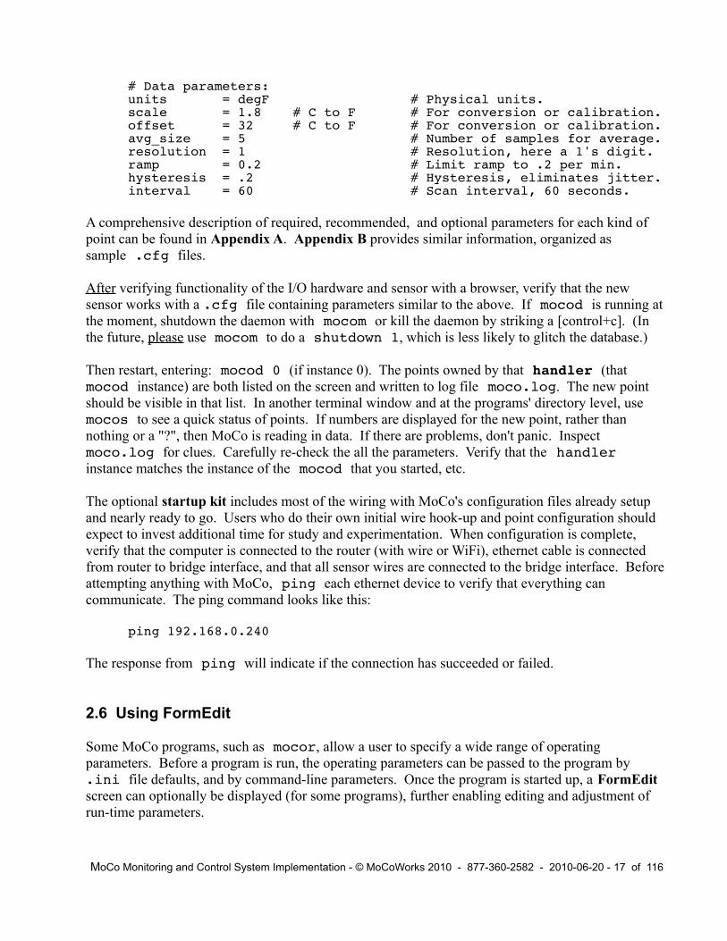
# Data parameters:units = degF # Physical units.scale = 1.8 # C to F # For conversion or calibration.offset = 32 # C to F # For conversion or calibration.avg_size = 5 # Number of samples for average.resolution = 1 # Resolution, here a 1's digit.ramp = 0.2 # Limit ramp to .2 per min.hysteresis = .2 # Hysteresis, eliminates jitter.interval = 60 # Scan interval, 60 seconds.
A comprehensive description of required, recommended, and optional parameters for each kind of point can be found in Appendix A. Appendix B provides similar information, organized as sample .cfg files.
After verifying functionality of the I/O hardware and sensor with a browser, verify that the new sensor works with a .cfg file containing parameters similar to the above. If mocod is running at the moment, shutdown the daemon with mocom or kill the daemon by striking a [control+c]. (In the future, please use mocom to do a shutdown 1, which is less likely to glitch the database.)
Then restart, entering: mocod 0 (if instance 0). The points owned by that handler (that mocod instance) are both listed on the screen and written to log file moco.log. The new point should be visible in that list. In another terminal window and at the programs' directory level, use mocos to see a quick status of points. If numbers are displayed for the new point, rather than nothing or a "?", then MoCo is reading in data. If there are problems, don't panic. Inspect moco.log for clues. Carefully re-check the all the parameters. Verify that the handler instance matches the instance of the mocod that you started, etc.
The optional startup kit includes most of the wiring with MoCo's configuration files already setup and nearly ready to go. Users who do their own initial wire hook-up and point configuration should expect to invest additional time for study and experimentation. When configuration is complete, verify that the computer is connected to the router (with wire or WiFi), ethernet cable is connected from router to bridge interface, and that all sensor wires are connected to the bridge interface. Before attempting anything with MoCo, ping each ethernet device to verify that everything can communicate. The ping command looks like this:
ping 192.168.0.240
The response from ping will indicate if the connection has succeeded or failed.
2.6 Using FormEdit
Some MoCo programs, such as mocor, allow a user to specify a wide range of operating parameters. Before a program is run, the operating parameters can be passed to the program by .ini file defaults, and by command-line parameters. Once the program is started up, a FormEdit screen can optionally be displayed (for some programs), further enabling editing and adjustment of run-time parameters.
MoCo Monitoring and Control System Implementation - © MoCoWorks 2010 - 877-360-2582 - 2010-06-20 - 17 of 116

FormEdit is an exclusive MoCo parameter editing feature that was designed to work on any operating system, any software or hardware terminal, over remote telnet or ssh links, and even with a low-speed modem. While it lacks the glitz of a GUI interface, it gets the job done.
If a -e switch is specified on the command-line, a FormEdit screen will appear when the program is run. Depending upon the program, a help screen may be displayed first. The FormEdit screen for mocor looks like this:
Enter data on cmd-line. Remember, SPACE BEFORE NAV COMMAND! (" h" for help.)
rpt_file -1---------------------------------------------------- Report File rpt_type 2: E everything, a active alarms, A defined alarms, o overrides, r remarks, u anything unusual, t4 4 columns, t7 7 columns, f & F output files, s only stealth points, S also stealth points. p_mask 3: * Points
Any 2 (not 3) below: rpt_span 4: 4h Duration (like 30m,8h,2d,2mo) rpt_from 5: From time (like 080123-1200) rpt_to 6: now To time (080210-0600 or now) Optional: out_file 7: Ex: results.tmp PARM ERROR: (none)
rpt_file [] 1:
Default parameters and parameters from the command-line will be immediately visible in the data-entry fields of the form. New parameters are entered at the bottom of the screen. The form is displayed directly above the computer's cursor. The long dashed line “---------” is FormEdit's cursor that shows the current field, and indicates where the data will appear once it is entered.
If you want to alter or enter data for the current field, just strike [enter]. The cursor will move to the next field. If data is to be entered for a field, enter the data and strike [enter]. The new text will replace whatever was in the field, and the cursor will move down to the next field.
MoCo programs usually sniff a parameter as it is entered to see if it passes the smell test. If the parameter has a flaw, FormEdit will lock to the current field until acceptable parameter data is entered. Error information is displayed at the bottom of the form.
When you get past the last FormEdit field, FormEdit will display:
Strike [Enter] if done editing, "b" to edit more, "q" to quit:
If all the parameters are as you wish, strike the [enter] key and the program will run.
Or, continue editing by striking “ b [enter]”. “b” stands for “backup”.
MoCo Monitoring and Control System Implementation - © MoCoWorks 2010 - 877-360-2582 - 2010-06-20 - 18 of 116

IMPORTANT: All non-data edit and navigation commands begin with a space character.
FormEdit provides various ways to navigate to the field you want to edit:
[space] b [enter] Move back to the previous field.[space] f [enter] Move forward to next field.[space] n [enter] Where n is a parameter number, jump to parameter n.[space] a text [enter] To append text to the current field.[space] [enter] Clear a field, setting it to be null.[space] x [enter] Exit FormEdit, and continue the program.[space] q [enter] Quit the program.
[space] h [enter] View a short help screen for FormEdit, itself.
2.7 Initial MoCo Startup
To complete the following steps, a few transducers should be connected to the bridge interface, the bridge should be connected to the router, and the router should be connected to the computer with MoCo installed on it. Important: Use the computer's browser to verify that there exists proper communication from computer to transducer. If unsuccessful with a browser, try pinging the I/O bridge. As problems arise, use the Troubleshooting appendix to help find the solution.
Program mocod is the heart of the system. It does the I/O, polls the sensors, does significant number crunching, checks for alarm conditions, talks to the database, and more. A mocod daemon or multiple mocod daemons are the first programs to be started. They continue to run as long as transducers are to be monitored and controlled.
Let's keep it simple – start with only one daemon. As the system grows more complex, expect to have several or more instances of the mocod daemon running. Each one, called a "handler, is numbered mocod0, mocod1, mocod2 etc. The handler name is specified with the handler parameter in the point's .cfg file.
For enterprise systems, MoCo uses a trick to assure that each handler name remains unique for the total system. At the enterprise (distributed computers) level, the handler name includes both the computer node-name and daemon instance, like: hal/mocod3
For this initial test, only the mocod0 handler is run. Therefore, all of the .cfg files should properly include handler = mocod0 for this startup test. The following command starts an instance of mocod. Without an instance number specified on the command line, mocod defaults to being handler mocod0. (For instances other than "0", an instance number is required.)
mocod # Start handler mocod0. (mocod.pl on Windows)
Because no parameters follow mocod in this case, it is necessary to strike [enter] a second time (after the short help message) to get mocod running. If all is well, messages regarding sensor-reads
MoCo Monitoring and Control System Implementation - © MoCoWorks 2010 - 877-360-2582 - 2010-06-20 - 19 of 116

are occasionally written to the screen. The terminal window will look something like this, except with only one to several input points at first:
...12:33:44 mocod0> GATW ? F - (startup)12:33:44 mocod0> GATW 55 F -12:33:44 mocod0> HumW ? % (startup)12:33:44 mocod0> HumW 67 % 12:33:44 mocod0> IATW ? degF (startup)12:33:44 mocod0> IATW 73.6 degF12:33:44 mocod0> OATW ? degF (startup)12:33:44 mocod0> OATW 34 degF 12:33:44 mocod0> WDirW ? deg (startup)12:33:44 mocod0> WDirW 40 deg12:33:44 mocod0> WGusW ? mph (startup)12:33:44 mocod0> WGusW 14 mph12:33:44 mocod0> WSpdW ? mph (startup)12:33:44 mocod0> WSpdW 2 mph 12:33:45 mocod0> OutFile ? pts (startup)12:33:45 mocod0> OutFile 1 pts12:33:46 mocod0> testCalc ? none (startup)12:33:46 mocod0> testCalc 1221 none12:33:46 mocod0> TClock1t 0 OnOff 12:33:44 mocod0> TClock1o 0 OnOff 12:33:44 mocod0> Tc1offo 1 OnOff ...
Run mocos to see a status report of all installed sensors. Typical results:
Alarm Val Val-Hist Time Rem-Age Remark Point OutFile 1 1 13:10 Alarms 0.00 0.00 cnt 13:10 Outside ........................................ OAT 43.7 44 degF 13:10 28 (startup) OATW 36.3 35 degF 13:09 WGusW 14 14 mph 13:09 WSpdW 4 4 mph 13:09 WDirW 56.5 30 deg 13:09 HumW 62 65 % 13:09 DewPW 24.5 24 degF 13:09 BaroW 29.972 29.98 in 13:09 Inside ........................................ IATB 68.8 69 degF 13:10 28 (startup) IATH 70.52 70.5 degF 13:10 17 (startup) IATsets 70 70 degF 13:09 IATW 74.2 74.2 degF 13:09 - GATW 55 55 F 13:09 Tc1offo 0 0 OnOff 13:06 Tc1ono 1 1 OnOff 13:10 TClock1o 1 1 OnOff 13:10 TClock1t 1 1 OnOff 13:10 testCalc 1222.6 1222 none 13:10 ladderc 1 1 logic 13:10
After awhile, run report program mocor to view history of all points written to history within the
MoCo Monitoring and Control System Implementation - © MoCoWorks 2010 - 877-360-2582 - 2010-06-20 - 20 of 116

last four hours:
mocor # Or, add the -e switch to pass through the FormEdit screen.
Try again with the -e switch. Strike [enter] to step through the FormEdit screen. At any edit-screen field, you can type " h" (space h) to see a brief help-screen that explains how to work the edit-screen. Just walk down through the screen by striking [enter] until at the bottom until mocor executes the report, displaying the report as before.
For command-line help, enter: mocor -h This is a way to get help for any MoCo program.
If all of the above worked as expected – congratulations! You have a functional MoCo system.
2.8 After Initial Startup
After initial startup, you are ready to begin adding the remaining sensors. Seasoned control engineers have learned that for applications more complex than lighting or irrigation, it is wise to monitor for awhile before implementing control logic. This is because monitoring reveals information that will impact control design decisions. In other words, for complex projects, get the monitoring working first.
If the system is to have more than several dozen points, consider how to divide the sensors between daemons. Time clock, calculation, and output points should probably reside together in mocod handler 0. In typical a situation, handler 0 should also be able to handle an additional two dozen inputs. Depending upon interval times, additional input points might be distributed 50 per handler. To reduce the probability of swamping a bridge with bursts of I/O requests, match a handler to one or two bridges.
When running multiple handlers, there is an easier way than spawning a terminal window for each handler. Except on Windows, instances of mocod can be started in the same terminal window by running them as background programs. Enter the following on the command-line to startup three handlers in the same window:
mocod 2 &mocod 1 &mococ 0 &
Except on Windows, the “&” tells the operating system to run the program in the background. All three daemons will display log-style data to the same window. Furthermore, reports and scripts can simultaneously be run from the same terminal's command-line. If data is displayed to the screen while you are typing a command, don't worry – the system will not garble any of your commands. All this action can be confusing on an busy system, but it works. You can always resort to running programs from several windows if the above suggestion creates too much confusion.
Startup sequences (as above) and shutdown sequences can be automated with a script. See the section on Shell Scripts in the Maintenance chapter for overview and tips.
MoCo Monitoring and Control System Implementation - © MoCoWorks 2010 - 877-360-2582 - 2010-06-20 - 21 of 116

3. Under the Hood
3.1 Data Processing
In short, MoCo's job is to read sensors, sanitize the data, compress data, and move the results to a database for storage. While doing these chores, MoCo can generate alarms and control output points based upon the values of input points and calculations. MoCo also includes tools for displaying status and history of data. The concept is simple, but as users evolve a system, they will find that complexity is the norm for any practical monitoring and control system. Life is good, but seldom simple.
Like most monitoring and control systems, MoCo defaults to sampling data in a kind of round-robin fashion. Yet MoCo allows the user to select a custom sampling interval for each point. For example, sampling intervals of 100 seconds for an outside temperature sensor and 12 seconds for an inside control-loop temperature sensor might be appropriate. Because MoCo's most time-consuming task is communicating with sensors, the user should select scan intervals with care – not too fast, and not too slow.
Polling, in general, is inefficient and slow. Unfortunately, most sensor input hardware leaves no choice. Traditional round-robin execution of ladder logic and other calculation points can be even worse because changes might leisurely propagate through other calculation points more slowly than desired. MoCo minimizes, if not eliminates, this problem with fast-response architecture features. However, response can be made even faster by allowing points to demand that their result be processed immediately by other calculation points. A user can setup a point's do_next parameter with the IDs of one or more points to execute immediately. Output points are always immediately triggered in this manner – unless the developer elects to do otherwise.
By default, calculation points are automatically re-calculated without interruption until all changes have propagated, thereby eliminating propagation delays – unless the developer disables re-calculation for a point. Recalculation can cause problems with some kinds of calculations, such as duty cycle calculations.
Compared to humans' ability to consciously and reliably monitor details, MoCo is capable of monitoring an extraordinary amount of data. Normally, however, a temperature or humidity value does not change from second to second, unless there is unfiltered noise in the data. The human brain is adept at filtering noise and ignoring static data; and likewise, MoCo has been designed to do the same. From the computer's point of view, the logging of static data can be the single biggest waste of disk storage space. Therefore, MoCo provides configurable mechanisms to prevent uneventful measurement data from swamping the database.
MoCo processes two types of data: analog and digital. Analog data can be highly processed, as described below. Digital data is minimally processed in a manner that does not change the appearance of the number, unless there is an override of some kind, or the true/false sense of the value is inverted (due to the invert parameter). Unlike analog points, a digital point's “clean”
MoCo Monitoring and Control System Implementation - © MoCoWorks 2010 - 877-360-2582 - 2010-06-20 - 22 of 116

and “working” values are identical.
Normally, a user does not have to consider whether or not to specify analog or digital because the driver automatically selects the most appropriate type. Why might a person want to deviate from the default? A time_clock is digital by default. However, if a user forces the time_clock to analog, the analog conditioning parameters shift into gear. With appropriate selection of ramp and interval, a time clock can create a ramped output. To override a driver's default data type, set the point's digital parameter as follows:
digital = 0 # For analog processing (resolution, hysteresis, etc.)digital = 1 # For digital processing (true/false can be inverted)
MoCo's analog data-conditioning mechanisms are a series of algorithms that compress data and render it human-friendly. All analog points can have their data processed by the algorithms. The following conditioning-parameters can be configured for a point in it's .cfg file:
interval # Number of seconds between readings, default=60avg_size # Number of readings in running average, default=1resolution # How fine the value (like 1, .5, .2...), default=1bad_high # Block data above this value from being processed.bad_low # Block data below this value from being processed.high_limit # Prevent a converted value from going above this limit.low_limit # Prevent a converted value from going below this limit.ramp # How much to limit changes per minute, default=nonehysteresis # Eliminates jitter. Default is 1/8 of resolution.scale # For calibration and conversions, default=1offset # For calibration and conversions, default=0
Analog data is processed and conditioned in the following order:
1. Scaling and calibration.2. Checking for bad data, data that is way beyond reasonable bounds.3. Applying high and low limits (clamping the value's range).4. Running-average for history value.5. Limiting ramp (limiting rate of change per minute) for the clean and history values.6a. Hysteresis for the history value.
6b. 1/10 the value of hysteresis for the working value.7a. Rounding the history value to specified resolution.7b. Rounding the working value to 10x finer resolution than the history value.
8. Programatic overrides.9. Manual overrides.10. Trigger shell commands.11. Alarms.
The number of decimal places for a value is automatically determined from the resolution parameter. For example, a resolution of 0.2 will create clean history values that look like 69.8, 70.0, 70.2, 70.4, and so on. With the 0.2 resolution, an internal raw value of 70.333333 is written to history as 70.4. For internal values and status displays, MoCo uses a working value that is 10 times finer in resolution than the history value. Continuing with the previous example, the internal working
MoCo Monitoring and Control System Implementation - © MoCoWorks 2010 - 877-360-2582 - 2010-06-20 - 23 of 116

value is rounded to 70.34 (note the additional decimal place).
Proper selection of the resolution parameter is desirable for a number of reasons. Most engineers and scientists would agree that there is no point in displaying higher resolution than the accuracy of the sensor. Some would go so far as to say that extra digits are a form of lying. If for no other reason, use appropriate resolution to keep the database from being flooded with redundant data.
ALERT: When viewing status reports (from the snapshot table) with mocos, you will see both the higher resolution working value and the clean value that was last written to history. If the point has an unusual resolution like 0.3, the clean history value may not appear to round correctly. Rest assured that it is being rounded exactly as requested, in increments of 0.3. Keep in mind that both values are captured to the snapshot table whenever one of the values changes to an new value. Of course, the high resolution “working” value is captured to the snapshot database table much more frequently than the 10x lower resolution “clean” history value.
Averaging and hysteresis are usually desirable because they reduce jitter in the system, reduce the noise on data written to history, and keep calculation points from repeatedly being jacked around. Note the that resulting values may be slightly different than expected, particularly if hysteresis is larger than 1/8 of the resolution parameter. An unusually small ramp and/or unusually large avg_size can also produce surprising results. Finding the sweet spot for these parameters typically requires thought and experimentation.
If the analog conditioning parameters are setup with care, clean data will be written to the database – and only when necessary. Note that the extensive cleaning described above is applied to two internal result-values, only: (1) point.h, the internal history value written to the history database; and (2) to the internal clean value, point.c, which has the potential of being manually overridden. The “c” is for “clean” value.
The working value, point.w, has 10x higher resolution than the previous two, and is cleaned only to the extent that (1) it's value can be optionally clamped between high and low limits, (2) it can have hysteresis applied to it, and (3) it is rounded. point.w is intended for internal calculations, where faster response is needed and where higher resolution can be beneficial. The “w” is for “working” value.
When doing calculations with a calc point, a user may choose one of a number of representations of a point's value. The preferred variant of a point's value for calc inputs is the working value, point.w (or simply point, for short). The working value has 10x greater resolution than the resolution specified by the history's resolution parameter.
Keep in mind that point.w has the capability of being overridden by a user (in case a sensor goes bad, or for debugging purposes). The afore mentioned clean value, point.c, is a cleaner, smoother value. This value is exactly the same as the value written to history, except that like point.w, it can also be overridden by a user. While very smooth and stable, point.c suffers ta disadvantage. Due to averaging or a ramp limit, it lags behind the less-clean point.w. There are other options, such as non-overridden values, but working point and clean point.c are most likely to be used as inputs for calculations.
MoCo Monitoring and Control System Implementation - © MoCoWorks 2010 - 877-360-2582 - 2010-06-20 - 24 of 116

The bad- or null-data “?” flag will display in values point.h (history value) or point.v (high-resolution value) in place of a number if the value cannot be read , or if MoCo recognizes the value as outside of normal limits. MoCo prevents the bad- or null-data “?” flag from reaching point.c and point.w. Instead, these variants have the last known good value. This prevents calculations and ladder logic from propagating spurious behaviors. Here follows a summary of useful variants:
.w Working value, override possible, hides missing/bad data, the default value
.c Clean (averaged) value, override possible, hides missing/bad data
.v High-resolution value without override, shown in status reports
.h Clean (averaged) value, written to history, shown in status & history reports
.val_raw Raw value from input driver, not yet scaled
For troublesome startup scenarios involving calculations, ladder logic, or time clocks, the above variants can be initialized in .cfg files. This tactic is seldom needed, but can be quite useful when needed.
When doing calculations and in other places where a parameter's value can be passed as a point-id as well as a pure number, MoCo can tell if the parameter 's value is a pure number or a point-id. If it is a point-id, MoCo translates the point-id and its attribute (like Xyz.c) to the number it represents. If the point-id is prefixed with a “-” (like -Xyz.c), it negates the the result. If the point-id is prefixed with a “!” (like !Xyz.c), it inverts the logic of the evaluated result. For example, a "!" will cause a false to become true (1) and a true to become false (0).
The “!” operator is particularly worth remembering because it is commonly useful in logic calculations, and for inverting a parameter used for gating (in other words, for enabling or disabling).
As mentioned, a point's value can be overridden manually or with programatic overrides. The user sets or removes a manual override via program mocom, which is MoCo's general purpose program for communicating with programs that are running. It enables a user to talk to a daemon – in particular mocod0, mocod1, etc., where the override actually occurs.
A user may choose to override a point's value for purposes of experimentation, debugging, or if a sensor has gone bad. Because history is history, the override will not "re-write" or lie to history. But, a note is written to database's history and snapshot tables showing that the point has been overridden. Unlike history and snapshot values, internal values point.w and point.c can be overridden so that calc points, for example, will receive the overridden values.
A manual override (sent by a user via mocom) behaves differently for an output point than for other points. For an output point, an override overrides the value that is sent to the output interface. It does so before the optional logic inversion would take place – if inversion were requested by .cfg parameter invert. Status and history reports show the value that is read back from the output interface (with the any invert being performed transparently).
An output-point override value is actually sent to the output device only if it is different than the previous output value and non-null. Therefore, before removing an output-point override, override it to the desired value, and then remove the override (by sending a null from mocom ) .
MoCo Monitoring and Control System Implementation - © MoCoWorks 2010 - 877-360-2582 - 2010-06-20 - 25 of 116

Note that if the point does have an invert configured, the output 1 or 0 will display as “1.” or “0.” in status reports or history reports. The decimal points inform a trouble-shooter that hardware and software values are inverted because hardware voltages are inverted.
Programatic overrides are performed by MoCo, as determined by the point's parameters. The results from non-output digital points can be forced to fixed values, or gated. Programmatically setting force = 1 forces the value or expression in the val_force parameter to override the point's result. The force, val_force, and gate parameters can be fed by numbers, other point variables, or expressions like: “(daytime && !shutdown)”
For non-output analog points, the gate value is multiplied by the point's value to create clean and working result-values. If gate is 0, the the result of a point is forced to 0. If gate is 1, the point is enabled to work normally. For output points, gate is applied to the value that is sent to the output device. If the output is digital, the resulting value is converted to an integer.
For safety reasons, force, val_force, and gate are inhibited from altering internal results on output points. This is because a point's value could be made to appear different in reports than the actual state of the output device. However, you can actually force an output device to a certain state with these programatic override variables, which is what you would want.
The various programmatic override parameters can be used to help place output interfaces in a safe configuration at shutdown – to zero, for example. The ini.shutdown variable is set to true when a shutdown has been requested by mocom. This variable can be used as a control signal for ladder logic or for forcing point values when a shutdown is about to occur. Because a delay of many seconds is typically requested before the shutdown occurs, internal logic will have time to react before the shutdown occurs.
When a point changes in some way, a person may wish the value-change to trigger a shell command. A shell command (command-line command) or shell script-name can be setup in various .cfg file parameters. This command will be executed when the trigger situation occurs. The command can be used to run programs that will transfer files, send email, or run a status report of relevant points, for example.
The shell command string to be executed is placed in the point's cmd_whatever parameter. The designer can cause ini or cfg variables to be automatically inserted into the command string by placing {point.attribute} in the string for each variable inserted. If the form is {.attribute} then the current point's ID is used. If the form is {point}, then point.w is used. The cmd_whatever parameter can “indirect” to the .ini file like this: ->ini.cmd_alarms. The mechanisms described in this paragraph enable the implementer to centralize shell commands, which can be a way reduce maintenance and human error on large systems.
The following parameters can contain shell commands:
cmd_c_0 # A point's clean value has gone false.cmd_c_1 # A point's clean value has gone true.
MoCo Monitoring and Control System Implementation - © MoCoWorks 2010 - 877-360-2582 - 2010-06-20 - 26 of 116

cmd_o_0 # A user has moved a point out of override.cmd_o_1 # A user has moved a point into override.cmd_a_H # Alarm H, for example, has been triggered and latched. # See the alarms chapter for a detailed description.cmd_outf # A file has been output from driver output_file.
Example:
cmd_o_1 = “override-mail.sh TClock1-“ # Say point is now overridden.
All points have the ability to be alarmed, assuming that alarms for the point have been enabled. Up to 28 different user-configurable alarms (for different situations) can be placed on a point, and each one having its own priority. Alarm thresholds and alarm text are setup in the point's .cfg file. A point's value and rate of change can be set to trigger an alarm.
Each alarm can be setup to latch, or not. Latched alarms will stay on until a user clears the alarm via communication program mocom. Whenever a point's alarm has been triggered, the point's highest priority alarm character is displayed in history and status reports.
Also with mocom, a user can trigger a point's manual “!” alarm along with his or her remark. This can be used to alert others in a maintenance team that there is an issue with the point. The manual “!” alarm is a latching alarm of the highest priority. See the chapter on Alarms for more details about alarms in general.
Missing data: If external hardware or network fail, MoCo will have no way to read current data from the sensor. Rather than display old-data or a zero (both of which would be lying), MoCo sets the data to a “?” to show that current data is unavailable.
Bad Data: Sometimes a sensor fails and consequently produces an extremely high or low value. Other times, extremely high or low values result from noise spikes. This is bad data. A user can trap bad data by setting the bad_high and bad_low parameters. Any value above or below these thresholds is considered bad data, which is replaced by a “?”.
The “?” flag replaces numeric data only in variants point.h and point.v. Other variants contain the last known good value.
When status or history reports show a question mark, it usually means that the sensor is unreadable at that moment or is in the process of failing. But, it also could be an indication of out-of limits data or a configuration error.
If point.h or point.v are fed to a calculation point, the “?” is propagated through the calc point to prevent the results of calculations that were fed with missing data to be misinterpreted as legitimate. If a point's missing data lingers and if the point's alarms are enabled, a “?” alarm is set. The “?” alarm is not latched, but it does overlay all other alarms except “!”. The “?” will go away when the point is again functional.
All points (except output points, themselves) have the ability to send their result to one or more output points for immediate transmission to the point's hardware interface. This is highly
MoCo Monitoring and Control System Implementation - © MoCoWorks 2010 - 877-360-2582 - 2010-06-20 - 27 of 116

recommended for outputs because the tactic minimizes output latency, thereby assuring that outputs have top priority.
A time_clock, for example, may send its output to several output points for a sprinkler system or lighting circuits. However, the time clock's result is not sent on to the hardware interface unless either the time clock's clean- or working-value have actually changed. Redundant transmission of data would waste network resources.
Similarly, all points except output points have the option to trigger other points to run immediately, without delay – in other words, without waiting for the scheduler to run the point. To make this happen, you can include the list of points to trigger in the do_next parameter. Multiple variables are separated by the pipe character. Example: do_next = pump3o|valve22o|saw1o The do_next trigger will occur only if a point's clean value or working value has changed. MoCo scheduling is fast enough for most situations; so be nice, and use this feature for non-output points only as needed.
All points have their own stopwatch timer capability. Stopwatch timers are useful for calculating on-time per hour, calculating duty cycle, staging a scene, etc. Each point's timer can be started, stopped, and reset programmatically by other points. A ladder logic point's result can be used to control its own timer. Any point can use use the time values from any other point's timer. See the section entitled Stopwatch Timers for details.
A point's data collection and processing can be totally halted by setting parameter disable = 1 in the point's .cfg file. A point can also be disabled in a live mocod daemon with mocom by setting disable to 1. In fact, mocom can change any cfg or ini parameter in a live mocod daemon. With the proper command, mocom can also cause any or all of the values to be dumped (displayed) from a live mocod daemon – a very helpful tool for debugging.
As an alternative to using a text editor, mocom can also change parameters in .cfg or .ini files. And, if so commanded, mocom can signal mocod to reload one or all .cfg files to mocod while it is still live and running. These latter features are primarily useful in situations where a system must stay up 24x7.
Each time mocom executes a command, the details are recorded in the moco.log file. See the chapter on mocom for a full description.
3.2 System Considerations
As mentioned in Chapter 1, MoCo's ability to run on common computer operating systems was a prime design objective. Perl goes a long way toward making this objective achievable. Yet because MoCo would like to be a "realtime" system, the multi-platform objective remains a challenge that perl cannot totally solve. Windows proved to be stumbling block because it is different from the other operating systems in many ways; it sometimes lacks some important operating system features that are available on the other operating systems.
The most critical needs of a realtime system are the following: ability for multiple processes to run
MoCo Monitoring and Control System Implementation - © MoCoWorks 2010 - 877-360-2582 - 2010-06-20 - 28 of 116

simultaneously, deterministic response (or at least “fast enough” response) to I/O needs, ability for activities to continue in parallel while waiting for an interface to respond, viable inter-process communications, and for the system itself to be bullet-proof (no crashes, ever). While most of these features are in some way available on Windows, they are often implemented differently than on the other three (all of which have nearly identical system-level functionality).
Purists might argue that MoCo architecture does not meet all the criteria of a “realtime system.” They would be correct. MoCo does not provide millisecond response to outside events. Some would argue that Windows and standard unix-like operating systems are not capable of realtime operation. And further, Ethernet ruins any possibility of deterministic response. Given these realities, MoCo attempts to provide response-times that are good enough for most monitoring and control applications, and leaves millisecond response time to smart bridges at a lower level.
The inter-operability dilemma was solved in a simplistic manner, which has proven to work well enough for MoCo. Instead of attempting a cross-platform implementation of forks, non-blocking tricks, software interrupts, etc., MoCo can run a number of mocod daemons. If one daemon is momentarily blocked while waiting for an interface to respond, the other daemons can take advantage of the wait time to do their work. Because mocod's code-execution time has been measured at less than 1% of the wait-times (I/O blocking and sleep time), efficient utilization of wait-time is important – something the user should consider when deciding how to assign I/O interfaces to different daemons.
Other challenges for multi-platform operability include inter-process communications and distributed processing – the ability to run MoCo on multiple computers at the same time, even if they are distributed world-wide and on different operating systems. In short, these challenges were were overcome by favoring ethernet as the hardware means for both computer-to-computer and computer-to-interface communications; and by using a SQL database for software interprocess communications, as well as for conventional storage of status and historical data.
Note that in multi-computer enterprise environments, SQLite must be replaced by a server-style database, such as PostgreSQL or Oracle. Such “enterprise” databases use internet protocols to implement their distributed-database features. While MoCo is designed to work with these and other common SQL databases, it is routinely tested only with SQLite.
In summary, mocod is the MoCo program that does the time-sensitive data acquisition and processing. Multiple instances of mocod run as daemons so that interface communications can be serviced without objectionable delays. The daemons on a single-computer system are named like handler = mocod0, mocod1, mocod2, etc. In a multi-computer network, the handler ID includes the node of the computer, as handler = robbie/mocod0.
When configuring the system, the user needs to consider how to assign the various interfaces to a daemon, or handler. It is usually wise to assign the time, calc, and output points to the same daemon, and start this time/calc/output daemon last in the startup sequence. Each I/O interface might be assigned to another daemon, or not. On the other hand, if the number of total points is below 50, and the sampling interval for input points is between 10 and 60 seconds, then one instance of mocod should be adequate. This decision hinges primarily on the response time of the bridge and the quality of the network.
MoCo Monitoring and Control System Implementation - © MoCoWorks 2010 - 877-360-2582 - 2010-06-20 - 29 of 116

There are a variety of ways to run multiple daemons in the background on a computer, and the methods are different on Windows vs. unix-style systems. The more sophisticated techniques require systems expertise that is beyond the scope of this document. Fortunately, there is an easy way to run multiple instances (daemons) of mocod. Just open multiple terminal windows on your system of choice, and run one instance of mocod in each window. For extra credit, jump to the chapter on Scripts to see how to conveniently run all handler daemons in a single window.
Other MoCo programs can be run in other terminal windows, as needed. A list of MoCo programs follows. Maintenance scripts are listed in the maintenance section.
mocod # The main moco daemon, aka handler.mocos # Display status of points.mocor # Display a historic report of points.mocom # Inter-program communication, user interface.
The programs listed above are run from the command line. They can be setup to run from icon-clicks, as well. While traditionalists believe that command-line interfaces are fast and efficient, most Windows and Mac users are more familiar with GUIs (graphic user interfaces) that are served directly from a program or from an internet browser.
At the time of this writing, GUI interfaces have not yet been created for MoCo. However, MoCo's programs and data structures have been carefully designed such that GUI interface software can be layered on top of the command-line programs, without the programmer having to touch a line of underlying MoCo code.
Web page designers prefer to get their dynamic web page data from command-line style programs. MoCo is free, open source software; and we hope MoCo users will generously contribute their GUI interfaces to the project in the same spirit.
Enterprise Features: MoCo and its I/O bridges are designed to be network-centric. This architecture was selected, in good part, to enable a scalable, failsafe architecture. Although MoCo comes stock with a low-fat database, it is also designed to work with a server-style database. This option enables MoCo's “nodes” to be distributed across the intranet or internet.
Critical applications usually require a failsafe network of computers with redundant nodes and a distributed database. MoCo facilitates this requirement by enabling one cluster of nodes to function as the master, while one or more other clusters act as slaves. The slaves monitor everything along with the master, but their ability to output to a bridge is blocked. This prevents more than one computer from sending output commands to an output point. If the master goes down, a slave can become the master. Of course, the transition procedure should be planned and tested in advance. This capability is facilitated by the no_output parameter in .ini and .cfg files.
MoCo Monitoring and Control System Implementation - © MoCoWorks 2010 - 877-360-2582 - 2010-06-20 - 30 of 116

4. Changing System Parameters with mocom
4.1 What mocom Can Do for You
mocom deserves its own chapter because it is the communications link between you and the mocod daemons that continuously run in their own private world.
mocom is a command-line program that is both versatile and quick to use. It works well over telnet and ssh terminal connections. Because mocom is a command-line program, it's operation may be less intuitively obvious at first. But its operation soon becomes second nature for most users.
You can do the following with mocom:
- Acknowledge alarms.- Set the “!” manual alarm.- Set or clear an override value for a point.- Send a remark to be displayed with its point on status displays and in history.- Change an ini or cfg parameter in a running mocod handler daemon.- Change parameters in .ini files, .cfg files, .rpt (report) files, .usr (user) files, and .lcl (localization) files.- Cause all ini or cfg parameters (for a point) to be dumped to the screen.- Cause cfg parameters to be re-loaded from files to a running mocod daemon.- Shutdown a handler daemon.
When executing any of the above, a short remark can be tacked on to the end of the command string. Remarks are displayed in status and history reports, along with alarm actions, parameter changes, or override actions.
mocom can be run in the same window as mocod handlers if mocod was started with the “&” option (mocod 1 &, for example) The “&” tells the operating system to run the mocod daemon in the background. This works on Linux, Unix, and Mac.
With MS Windows, mocom is run from its own window. And, the mocod handlers are each run in their own windows.
4.2 Operation
mocom's help screen is shown below. Except when requesting the help screen with -h, the first parameter is always the initials of the user – the user's handle. Take note that mocom will not allow the user to execute its commands unless the user has a .usr file configured, with at least one parameter inside. This is because mocom, in unfriendly hands, could do some damage.
MoCo Monitoring and Control System Implementation - © MoCoWorks 2010 - 877-360-2582 - 2010-06-20 - 31 of 116

The object argument follows the user's handle on the command-line. The object includes the names of entities like the ini parameters, a point, or a configuration file. Next, the user enters parameter-name and parameter-value, followed by an optional remark. This information is all entered on one line in one shot – no fuss.
Alarm commands and the remark command are different than the others in that they need one less argument than the others. The following help screen should make mocom's usage more clear:
Usage: mocom is a command-line MoCo communications program.
mocom [-switches] your_handle object parm-name value remark... msg_to=_msg_to_ <-- seldom needed option
Switches: -h for Help, -b for batch.Object arg: Single point, points, point-mask, file-name, ini/cfg.Description: Communication program to change/view parms in running daemons and configuration files. Also, control alarms & send remarks.Examples: - sw,handle,object,parm-name,value - - remarks - mocom -h HELP mocom rw IAT - Acknowledge alarm on point IAT. mocom rw hat - OK now! Ack alarm on HAT pt, with remark. mocom rw HWP ! Fixing it. Manually set alarm "!" on HWP. mocom rw HWP ? Hot water pump is in repair. (remark) mocom rw iat override 70 Override point IAT to be 70 deg. mocom rw IAT override - Turn off the override. mocom rw oat units C Change live pgm's OAT units: units=C mocom rw OAT c xyz "" Change live pgm's xyz to be null. mocom rw CWT.cfg units F Cng CWT units in .cfg file: units=F mocom rw XY reload .cfg file changed, so reload XY.cfg. mocom rw IAT dump Display/dump live pgm's IAT cfg hash. mocom rw 0 dump Display/dump live mocod0's ini hash. mocom rw 2 dump Display/dump live mocod2's ini hash. mocom rw 3 xyz 123 Cng xyz to =123 in live mocod3 ini. mocom rw moco.ini ABC 456 Cng ABC to =456 in moco.ini file. mocom rw mocod2.ini R66 -22 Cng R66 to =-22 in mocod2.ini file. mocom rw 1 reload Reload mocod1's cfg's & restart. mocom rw inside.rpt rpt_span 6h Change parm in .rpt file. mocom rw 2 shutdown 60 Fixing UPS Shutdown mocod2 in 60 sec.
Alarm acknowledgments and remarks are sent more often than any other single command. Therefore, when mocom's object is an alarm or remark, the point-id can be all lower-case. Point-ids for parameter changes, overrides, dumps, and reloads are also insensitive to case. However, if the object is a file-name, the file-name characters must be identical in case to the actual file-name.
The point-id argument in an alarm or remark command can contain wild-card characters so that multiple alarms can be acknowledged with just one command. As a safety precaution, however, wild-card characters are not allowed in commands that change an ini or cfg parameter. When using wild-cards, remember to place double-quotes around the point-id argument. The quotes prevent the operating system from interpreting the wild-characters before they get to mocom.
When asking mocom to cause mocod to dump its cfg or ini parameters to the screen, be
MoCo Monitoring and Control System Implementation - © MoCoWorks 2010 - 877-360-2582 - 2010-06-20 - 32 of 116

aware that the handler dumps the result to the terminal screen on which the mocod daemon is running – which may be different than the window in which mocom is running.
For security reasons, mocom will refuse to function unless a moco-sm.usr system manager's file is on the system and is in the same directory as the other .usr files. Do not delete it.
MoCo Monitoring and Control System Implementation - © MoCoWorks 2010 - 877-360-2582 - 2010-06-20 - 33 of 116

5. Points: Input, Output, Calculation, and Time
5.1 Points in General
MoCo processes external and internal units of variable-data as "points." A point is a common industry term for an external transducer value. Some monitoring and control systems have functional internal variables, which their designers call "blocks." Because MoCo handles external and internal variables quite similarly, all such variables in MoCo are called points: input points, time points, calc points, and output points.
For large systems, point-id naming strategy can be one of the most important decisions a designer makes. This is be because MoCo reports provide wild-card selection capability, which enables a person to quickly specify a relevant report – if his or her chosen naming strategy so enables. For example, if MoCo covers several buildings numbered 1-8, the point-id might start with the building number. The second character might be T for temperature, L for lighting on/off, H for HVAC system points, etc. The last character could designate the type of point, and so on.
The following wildcard characters (same as for Linux and similar to Windows) are supported by MoCo reports:
* Zero or more characters? Exactly one character[abcde] Exactly one character listed[a-e] Exactly one character in the given range[!abcde] Any character that is not listed[!a-e] Any character that is not in the given range
Point-ids should be ten characters or less. While MoCo software can handle point-ids of any length, reports will be difficult to read if point-ids are greater than ten characters. For the same reason, keep the units name to five or less characters.
Point-id characters must be: a-z, A-Z, 0-9 or _. At least one character in the point-id must be a non-numeric character, so that MoCo will not mistake the ID for a number.
MoCo's point drivers can read constants and variables that have been input from the .ini files, and other system variables. This is done via the reserved point-id, “ini”. If ini is used as a point-id, MoCo assumes that the variable is a system constant or variable, and not a point variable. Therefore, do not use ini as a point-id. And for security reasons, system and exec are also to be avoided as point-ids.
Point-ids are case-sensitive for setup, such as for .cfg files and the database. However, to prevent case from being an annoyance when specifying reports, the name-masks (selection criteria) for specifying the scope of a status or history report are not case-sensitive. In many cases, mocom is insensitive to case. You can, and should, use upper or lower case for display aesthetics; but avoid using upper and lower case to differentiate one point from another.
MoCo Monitoring and Control System Implementation - © MoCoWorks 2010 - 877-360-2582 - 2010-06-20 - 34 of 116

Associated with each point are a number of parameters, which originate from the point's .cfg file. Once a program starts running, it works with both the original constants and with new internal cfg variables. The name we use for run-time cfg constants or variables is “attribute.” In this document, if “cfg” does not have a leading dot, it refers to a program's run-time cfg constants and variables, and not the original constants from the .cfg file. The same convention is used for “ini” constants and variables.
The software that implements a point can access not only the main point value, but it can also access a large number of point attributes. From the user's perspective, a point-attribute is represented as: point.attribute. (Replace “point” with the point-id, and replace “attribute” with the attribute name.) Think of attribute as directly representing a point's cfg constants and variables, or properties. Likewise, user software can access ini constants and variables as ini.attribute. (Replace “attribute” with the attribute name, but leave “ini” as ini.)
A subset of the attribute is the point's “variant.” The point has a primary working value, which is represented as point (or, with more verbosity as point.w). The point also has a number of other values, which we shall call variants. In this document, when you see the form “point.variant”, you should understand this to mean one of a points's variant values. For example, h is a variant value that is written to the history database. It is written as: point.h
Here follows a summary of useful variants:
.w Working value, override possible, hides missing/bad data, the default value
.c Clean (averaged) value, override possible, hides missing/bad data
.v High-resolution value without override, shown in status reports
.h Clean (averaged) value, written to history, shown in status & history reports
.val_raw Raw value from input driver, not yet scaled
For troublesome startup startup scenarios involving calculations, ladder logic, or time clocks, the above variants can be initialized in .cfg files. This tactic is seldom needed, but can be quite useful when needed.
The point's name parameter is a 0-20 character name that is displayed in some reports. Parameter desc is a 0-40 character description that is displayed in some reports. Like most everything else that is point-centric, name and desc are setup in the point's .cfg file.
By now, it should be clear that each point has its own configuration file that is named after its point-id, like: OATi.cfg or IATi.cfg. As a software sanity check, the .cfg file also contains the point-id inside the .cfg file, like: p = OATi. Therefore, take care when creating a new .cfg file for a new point from an existing file (or a template file), which you will do many, many times. If you change the file-name, you must change the internal p = point. Both must match.
Here's a suggestion for reducing human error: When cloning a .cfg file, always save to the new file-name as the first step, and always change the p = point-id as the second step.
MoCo Monitoring and Control System Implementation - © MoCoWorks 2010 - 877-360-2582 - 2010-06-20 - 35 of 116

The .cfg file can be edited with any text editor, the simpler the better. When using a "word processor," take care that it saves the text in pure text mode so that it does not insert invisible formatting code into the file. Make certain that the line-termination is LF (line-feed).
mocom also provides an alternate way to quickly change a parameter's value. mocon logs all changes, which would be of value to system mangers who run a tight ship.
Each .cfg file contains from several to a couple dozen parameters. Think of the parameters as a subset of the run-time point attributes. The parameters are represented in the file as: name = value or name = "value". Positioning and spaces are not critical in the file, except when there are spaces in the value string, itself. If there are spaces in the value string, then double-quotes (or some other means) are required to encapsulate the text. Never use single-quotes for this purpose.
MoCo programs read and write parameters to configuration files using subroutines called nvGet and nvPut. These subroutines are capable of handling arrays and difficult characters by using more sophisticated encoding techniques, but we will stick with simpler examples here. Note that comments can be placed to the right. Comments must begin with a “#” character. Linux/unix users will be familiar with these conventions, as they are nearly the same as for shell scripts. Examples follow:
ramp = 0.1 # A number, no quotes req.handler = mocod0 # No quotes needed.name = "Inside air Temp" # Spaces, so quotes.desc = "This is a very long sentence " "that takes up two lines." # They auto concatenate!array[0] = 123array[1] = 456 # Array elements.
In cases where a numeric value is expected for a parameter in the .cfg file, it goes without saying that a numeric value can be entered. More interestingly, a point's variable-name, like point or point.c, can be entered in many cases where a numeric value is expected. And even better, an expression containing variable names, logical operators, and arithmetic operators will work. In Appendix A, parameters with this ability are underlined.
These subtle but powerful features enable a point's numeric parameters to be controlled from other variables in sophisticated ways at run time, only to be limited by an implementer's imagination, or his desire for obscuration. When using an expression instead of a simple number, remember to leave spaces between operators and variable-names, and to quote the expression if it contains spaces. However, parentheses and the two operators “-” and “!” can live without spaces.
As the number of points increases beyond 50, users may prefer to have points hidden from view in reports. For example, calculation points often contain intermediate results that will be of little interest once they are configured and properly working. To hide a point, set: stealth = 1. Reports provide a means to display or not display stealth points, as desired.
The point's point_type need not be identified in the .cfg file because MoCo can determine the point_type from the driver that has been specified. The different types are described in
MoCo Monitoring and Control System Implementation - © MoCoWorks 2010 - 877-360-2582 - 2010-06-20 - 36 of 116

more detail below.
Most parameters are optional, but a few are required for each point. Please take care when setting up these parameters in the .cfg files. If no driver name (or a misspelled driver name) is specified in the .cfg file, mocod will report an error, or possibly even fail at startup.
5.2 Point Scheduling
By default, points are scheduled to be processed at the interval specified in the point's .cfg file. With the exception of interval-related math like duty cycle calculations, the intervals selected for typical applications usually range from 1 to 120 seconds. If not specified, 60 seconds is default.
However, points can also be scheduled immediately by a do_next trigger from another point. While do_next processing may not be needed for input points in simple monitoring applications, it can become an important consideration with calculations such as ladder logic and math expressions; and, do_next processing is the norm for scheduling output points.
With certain kinds of calculations, a person might need point processing to be performed on the interval, only. To assure this, set intv_only = 1. This forces a driver to run only at the specified time. It will not allow a calculation to be run in a recalculation loop (which would be desirable in most other situations).
In other cases, a person might desire to have a calculation performed only when quick-scheduled by another point's do_next parameter. For example, an application might need a calculation triggered only when a time clock changes state. In this case, set interval = 0 in the calculation point's .cfg file. If the calculation point needs to be do_next triggered from the leading edge only, set the target point's parameter cng_filter = 1. If the calculation point needs to be do_next triggered from the trailing edge only, set the target point's cng_filter = -1.
The cng_filter option is also useful for situations where a time clock or ladder logic point is setup to turn something on, but you do not want the activating point to be able to turn the device off ( or visa versa). In this case, another source-point's true-to-false transition might be setup to turn the output device off. This is one of those rare situations where an output point might be fed from two sources: one source to trigger the output on, and the second source to trigger the output off. The cng_filter parameter makes this scheme easy to implement, eliminating the need for at lease one extra ladder logic point.
Except for output points, a point's processing usually occurs on its interval (and occasionally at other times, mentioned earlier). An output point, on the other hand, is normally executed immediately after it's source point changes value. The source point contains a list of target points in its do_next parameter, like do_next = lights1|lights2|lights3. While do_next is normally for output points, it works as well for quick-scheduling any kind of point. The catch is that any point (including output points) that are triggered by a do_next must be on the same handler as the source point.
MoCo Monitoring and Control System Implementation - © MoCoWorks 2010 - 877-360-2582 - 2010-06-20 - 37 of 116

In cases where the source point is owned by another handler or on a different computer, an output point's source_pt parameter is the only way to link to a source point. Parameter source_pt can even accept an expression that contains logic and math. If source_pt contains a point or points that are not in the handler, data for the foreign point will be automatically obtained via the database.
Note that the process of waiting for a source-point's interval and obtaining data from the database introduces delays resulting from polling, database-write latencies, and network delays. Consequently, the system designer is advised to keep associated calculation points and outputs within the same handler, as often as possible. In other words, do not use source_pt unless necessary.
If properly implemented, these implementation tradeoffs will be transparent to the end user. From the developer's perspective, they will be of little interest for simple monitoring applications. However, they will become more interesting to the developer of larger systems as time clocks, timers, counters, and ladder logic come into play.
5.3 Input Points
The typical input point receives data from a single external sensor, processes the data, and sends a sanitized result to history and various other places. The processing includes units conversion, scaling, spike elimination, averaging, rounding to resolution, and application of hysteresis. The specific conditioning parameters must be setup in the point's .cfg file. These processing features were described in detail in Chapter 3. Under the Hood – It's All About Data.
But before discussing typical sensor-driven input points, we look at several special categories of input points that do not receive their data from an external electronic sensor. Point data can be input from a web page or file. Drivers input_from_web and input_file are the means for inputting point-data from a web page or file. See: 2.5 Hardware Transducers and I/O Interface Setup for a more detailed explanation.
Obtaining data from a Davis Weather Station is a good example. The Davis Weather Station has optional software and hardware that connects to a Windows PC. The Davis software (on Windows) creates a customizable web page (or pages) and ftp's them to a web server. MoCo driver input_from_web reads the web page and feeds the weather data to points on MoCo, like OATW, HumW, DewPW, BaroW, WSpdW, WGusW, and WDirW.
[This will probably be deprecated because calc_expression covers this functionality:] A manual input point is typically a manually-entered value that can be used as a set-point or limit. A person might choose to implement a set-point with a manual input so that the set-point value will be visible in point reports.
The driver for a manual input point is: input_manual. The data value comes not from a sensor, but from parameter val_manual in the point's .cfg file. The value for val_manual can also come from another system variable or expression that evaluates to a number. Because there is no real sensor associated with a manual point, only the following parameters are likely to be needed: p, name, desc, driver, handler, val_manual, units, and optionally
MoCo Monitoring and Control System Implementation - © MoCoWorks 2010 - 877-360-2582 - 2010-06-20 - 38 of 116

snap_fmt, which is used by mocos for status reports.]
An alarm point is a system variable that displays total alarm counts. It displays the information in a format like 12.34, where 12 is the number of unacknowledged alarms and 34 is total of active (triggered) alarms. The driver in this case is: input_alarm_tally. The following parameters are recommended for an alarm point: p, name, desc, driver, handler, units, interval, and optionally snap_fmt.
The coverage of input_alarm_tally is determined by the scope parameter. If 0, the alarm tally covers only the handler's points. If 1, it covers all of the node's (computer's) points. If 2, it covers all points in a distributed system.
From this point on, we discuss conventional input points that have sensors in the real world. In addition to the description below, sub-chapter 2.5 Hardware Transducers and I/O Interface Setup provides a practical overview of the setup process.
When setting up an external sensor, a broad range of skills and knowledge can come into play: physics, electronics, use of tools, networking, software, trouble-shooting skills, operating system savvy, manual-reading skills, and Googling for missing information. Consequently, the process can be a challenge for users who are new to monitoring and control. The uninitiated might find that solving a simple problem takes longer than an episode of CSI, where TV actors can solve a complex crime in less than one hour.
MoCo hardware is ethernet-centric. Therefore in many cases, the implementer can use a browser on the network to verify that the interface hardware and sensors are working. Do so before attempting to get the data into MoCo. The following supported I/O bridges can be configured and tested via a browser: HA7Net, OW-Server, WebControl, ISY-99i, and EMACSYS.
Once the interface has been verified working, it is time to figure out how to associate the sensors with the internal MoCo point-ids you have chosen.
For the HA7Net and OW-Server I/O bridges, you use the web interface via a browser to identify the 16-character unique ID of a 1-wire sensor. Using a simple text-editor, begin setting up the IATB.cfg file. (Of course, choose your own short point-id for the point.) Enter the following, except substitute values that match your situation:
# IATB - Inside Brewery Air Temperature.
# Device parameters:p = IATBname = "Brewery Air Temp"desc = "Inside Near Brewery Air Temperature"device_id = B50000027B7C1A28 # Unique 1-wire serial number.part_id = DS18B20 # Optional for this driver.net_addr = ->ini.net_addr_ha7net # To 192.168.0.250 in .ini file.driver = input_ha7net_temphandler = mocod0 # Program clone instance: 0,1,2,3...
If the I/O interface had been a WebControl bridge, then the device_id would have been t1 to
MoCo Monitoring and Control System Implementation - © MoCoWorks 2010 - 877-360-2582 - 2010-06-20 - 39 of 116

t8 for 1-wire temperature sensors. On the appropriate WebControl bridge web page, you need to associate the unique 12-character 1-wire serial number (which WebControl displays) with the t1 to t8 ID. MoCo is then exposed only to IDs like t1 to t8. The following points on WebControl are not 1-wire I/Os, but individual I/O ports: Digital inputs are straight TTL-level digital inputs like d1 to d8; and analog inputs are 0-10v analog inputs like a1 to a3. The single humidity input is identified by h1. TTL outputs, which can be read as inputs, are identified as o1 to o8.
Suggestion: Each I/O bridge has its own personality. See Appendix D for details that may not be in the manufacturer's manual.
Verify that the new sensor works with the parameters you entered, similar to those above. If mocod0 is running at the moment, terminate it with mocom by entering:
mocom 0 shutdown 5
The “5” in the above command is the number of seconds the driver is to wait before quitting. Then restart, entering:
mocod 0 (if instance 0).
The points owned by that mocod instance (aka handler) are both listed on the screen and written to log file moco.log at startup. The new point should be visible in that list. On a different terminal window, use mocos to view a quick status of points. If numbers are displayed for the new point, rather than nothing or a "?", then MoCo is indeed reading in data. If problems, inspect moco.log for clues. Re-check the accuracy of the parameters. Verify that the handler name's trailing digit matches the instance of the mocod that you started, etc.
The most difficult part is done. Configure the point's data-compression parameters, similar to the following:
# Data parameters:units = degF # Physical units, up to 5 characters in length.# scale and offset can be used for units-conversion and for calibration. scale = 1.8 # C to Foffset = 32 # C to Favg_size = 5 # Number of samples for running average.bad_high = 120 # Block if above 120. Probably bad sensor.bad_low = -20 # Block if below -20. Probably bad sensor.high_limit = 100 # Clamps the converted value to no more than 100F.low_limit = 40 # Clamps the converted value to no less than 40F.resolution = 1 # For numbers like -5, 32, 68, etc.ramp = 0.2 # Restricts change to less than .2 per minute.hysteresis = .2 # .2 hysteresis (1/8 of resolution is default).interval = 60 # Read point every 60 seconds.snap_fmt = "1|a|Inside ........................................"
Most of the above are optional. If unable to decide on a data-compression parameter's value for the moment, rest assured that most have reasonable defaults.
Optional parameter snap_fmt is used for ordering and labeling the display in a mocos status
MoCo Monitoring and Control System Implementation - © MoCoWorks 2010 - 877-360-2582 - 2010-06-20 - 40 of 116

report. It is made up of three sub-fields, separated by "|" (pipe) characters. The first two sub-fields are used for sorting, major and minor. If, for example, the third (Outside...) field is included, it will be displayed as a header line before "outside" sensors are displayed in the mocos report.
If parameter invert = "." is in the .cfg file, then a digital input is inverted, and a decimal point is appended (like 0. or 1.) so that a person viewing a report will know that the value was inverted by the point's driver. The feature is desirable because hardware inputs sometimes have reversed sense (inverted voltage).
A comprehensive description of required, recommended, and optional parameters for each kind of point can be found in Appendix A. Appendix B shows the parameters as they might appear in .cfg files.
5.4 Conventional Output Point
After a developer has successfully setup input points from a bridge, the steps for setting up an output point will be familiar. Perhaps the biggest difference between input points and output points is how they receive and send their data.
Points other than output points specify the sources of their data; and they can optionally send their results immediately to one or more other points, usually output points. Output points, on the other hand, do not normally choose their [non-output] source points. Rather, the source-points determine to which output points they send their result.
Although only one digital point ordinarily sends to a given digital output point, it is theoretically possible for more than one time clock or ladder logic module to send their results to an output point. Trouble shooters should keep in mind that two points sending to the same output can produce interesting results. However, as stated earlier, it is quite normal for a non-output point to send its result to more than one output point.
Points such as ladder logic points that send their result to output points by do_next triggers can be programmatically inhibited from triggering their configured output points. To regulate output point XYZ's output in this manner, the result from time clock ABC is fed to ladder logic IJK's enable_out parameter. If enable_out evaluates to true, outputs are propagated from ladder logic IJK to output point XYZ. If false, then results from point IJK are blocked from getting to the output point XYZ. The enable_out parameter can accept an expression, like: “(timeclk3 == 5)” Note that mocod does not block non-output points from receiving the trigger – only output points are blocked when enable_out = 0.
If an enable_out goes from false to true for a ladder logic point (or any other non-output point), a trigger is generated so that the current state of the point will be propagated to the output point, at that instant.
Yes, the above scenario is difficult to comprehend in one reading. But, the technique can be very handy for situations where outputs are being sequenced in a complex manner.
MoCo Monitoring and Control System Implementation - © MoCoWorks 2010 - 877-360-2582 - 2010-06-20 - 41 of 116

Output from all points will be blocked if .ini variable no_output is set equal to 1. An output may be individually blocked with .cfg variable no_output. However, if a point's no_output parameter is set to -1, output is enabled for that point even if the global no_output is 1. The no_output capability is useful for testing and it is essential for setting up redundant enterprise systems.
MoCo's output points additionally have the capability to create on-pulses or off-pulses of specified length, which are triggered from a leading edge, trailing edge, or both edges of the incoming value. This facilitates controlling contactors (latching relays) that are turned on and off from separate on- or off-pulses.
As with input points, read notes in Appendix D regarding the specific bridge. Then, verify an output interface's functionality with a browser before attempting a connection with MoCo. After verification, setup the output point's .cfg file.
To assure the fastest responses, it is important to keep in mind that the the output point must be on the same computer and handled by the same handler (mocod daemon instance) as the point or points that send their values to the output point. In other words, the output point cannot receive rapid-sent do_next values from outside its own handler. This, in practice, should not be a hardship in most cases because the I/O bridges are all on a network, easily accessed for input or output by any computer or handler. Therefore, input values can be easily read into any handler, and outputs can be sent from any handler to the network interface.
For performance reasons, the following option should be left as a second choice: an output point has the ability to call for and receive a point's value from any point in a networked MoCo cluster. But because it may receive external values through the database in this case, values from MoCo handlers external to the output point can be delayed for some seconds plus scan intervals.
To enable this source of data, set the output point's [normally ignored] source_pt parameter to the source point-id, which is presumably configured on another computer. The source point may be a variable or it's variant, or even an expression. source_pt, if defined, takes precedence over source points that are sent from other points via the do_next parameter. In other words, if source_pt is defined, then do_next results are ignored.
Testing an output is slightly more complex than testing an input because you also need to setup a point or points to drive the output point. One way to do this is to setup a time_clock that creates an on or off value every 5 minutes. Even simpler, setup an input that uses the input_file driver to read values from a file, as described in 2.5 Hardware Transducers and I/O Interface Setup.
Setup the input point's .cfg file so the input point will send its output value to the output point's driver, as: do_next = Test7o. Use your own point-ids, of course. To control three outputs at the same time from the same source-point, configure the source-point similar to this: do_next = Test7o|Test8o|Test9o Then manually toggle the input point's source value in the file on and off using a simple editor. Don't forget to save the file each time you make a change. If everything is setup correctly, the electrical output from the I/O bridge will track the input each time the file is saved.
MoCo Monitoring and Control System Implementation - © MoCoWorks 2010 - 877-360-2582 - 2010-06-20 - 42 of 116

A simple digital output .cfg file for a WebControl I/O bridge might look like the following:
# Output Point for Sprinkler Zone 1. Source is Zone1L.
p = Zone1oname = "Sprinkler Zone 1"desc = "Output Point for Sprinkler Zone 1"device_id = o1net_addr = ->ini.net_addr_wc0 # Refs IP-address in .ini file.driver = output_webcontrol # WebControl bridge.units = OnOffsnap_fmt = 8|b
An output point's .cfg file for a HA7Net I/O bridge would look similar, except that device_id would be the 16-character ID of a 1-wire output device, and the driver name would be output_ha7net_digital. With the ISY-99i bridge, an Insteon device's device_id would look like 3C.20.A1, and an X10's like C3.
An output point will invert logic levels if parameter invert is set to “.”. An output can be forced to a value by setting over (override) to the desired value in the .cfg file. A user can override a point's output via mocom while mocod is running.
An output point's actual output can also be programmatically forced to a specific value (similar to a manual override) by setting parameter val_force to the desired value and setting force to true. Digital points invert this value if inversion is called for. These variables impact only the state of the output device, and not the read-back value in reports. For safety reasons, force, val_force, and gate are inhibited from altering the internal result of an output point, because altering the internal value could obscure the actual value of the output device in reports.
Digital output drivers have the ability to create an output pulse when the source changes logic level. This feature is useful for triggering a contractor to turn on a room full of lights or a large motor, for example. To activate the pulse option, set parameter pulse_trig to trigger on the edge of the incoming source logic level by setting pulse_trig equal to one of the following: up, down, or both. Set parameter pulse_sec to the number of seconds desired for the pulse. An example follows:
# On-pulse Output Point for Time Clock 1. Source is TClock1t.
p = LitesONoname = "Lights-on Pulse"desc = "Lights-on Output Pulse"device_id = o2net_addr = ->ini.net_addr_wc0 # Refs IP-address in .ini file.driver = output_webcontrol # WebControl bridge.units = OnOffpulse_trig = up # <----pulse_sec = 10 # <----snap_fmt = 8|c
An output .cfg file for a HA7Net I/O bridge would look similar, except that device_id would be the 16-character ID of a 1-wire output device, and the driver name would be
MoCo Monitoring and Control System Implementation - © MoCoWorks 2010 - 877-360-2582 - 2010-06-20 - 43 of 116

output_ha7net_digital.
5.5 Outputting Points and Their Values to a File
The output_file driver enables a person to output a number of points to a file. While mocod treats this point as an output point, it differs somewhat from other output points – let's consider it a maverick because it differs in the following ways:
1. The output_file driver writes to a file, rather than I/O bridge connected to transducers.
2. This point can output more than one point-value.
3. The point that gets displayed or written to history is the quantity of points written to the file. If a file failure occurs, "?" gets written to history.
4. Other points do not send their results to this output point. The list of variables to be output are listed in its .cfg parameter, variables. Example: variables = IAT|OAT|WSpd.c. Note that the latency can be several seconds plus the scan interval.
5. As illustrated above, variants of a value (like point.c) can be written to the file, which can be handy.
6. This output point can automatically retrieve point values from any point in a networked MoCo cluster. It can even get its value from an expression. However, if a point is external to the handler, accessible variants are limited to the working value and the clean (.c) value. Also keep in mind that values from MoCo handlers external to the output point may be delayed some seconds due to scan intervals and database latency.
7. Every time the file is written, an external shell script can be triggered by the cmd_outf parameter. The command script can be setup to do things like ftp the file to another computer or web site. The “outf” in the parameter name is derived from “output file.”
In the interest of efficiency, output files are written only when a piece of data changes. And consequently, a script command is triggered only when data changes.
The output file can be created by two different means, (1) by writing name = value pairs to a file, and (2) by populating a template with values.
5.5.1 Name = Value Files
Once an output file has been written, a user can edit the file to have a nicer layout. Comments are allowed. From that point on, new data will be written to the file, and yet the new format will be preserved. When numeric data is written to the file, it is written with a consistent number of decimal places, attempting to be compatible with the point's resolution parameter.
Even after being edited, the file can be read by the input_file driver on another MoCo system.
MoCo Monitoring and Control System Implementation - © MoCoWorks 2010 - 877-360-2582 - 2010-06-20 - 44 of 116

This trick is a worthy alternative for those who do not wish to use an enterprise-style distributed database – simply output a file on one computer; input the file on another.
An example of a .cfg file for the output_file driver follows:
# OutFile.cfg - Output File
p = OutFile # This point's ID.driver = output_file # Output driver name.handler = mocod0 # The daemon, "0" in this case.variables = IATW|IATB|IATH # Three points to get, and write.out_file = OutFile.txt # Where to send the data (see below).interval = 30 # 30 second write cycle.
An example of the output produced by the file follows. Note that the file was one-time edited for positioning and comments, and thereafter the oroginal layout was preserved:
# OutFile.txt – Several inside points
IATH=73.03 # HVAC RoomIATW=73.6 # Living Area, Davis Weather StationIATB=65.8 # Brewery Area
datetime = "2010-02-17 19:07"
5.5.2 Template-driven Files:
If a template file is to be stuffed with data, parameter tmpl_file must contain the name of a template file. The output_file driver will then stuff a template with data values. Although graphics web developers will find this feature a godsend, it can also be used to quickly create a cosmetic text-based display.
First, the developer sets up a template. The template can be a html web page, or just plain text. Instead of including static numbers in the file (which, of course, would be old history in seconds or minutes), the variable name of each desired point is included within the text. For example:
Wind Direction .. {WindDir.c{{ degWind Speed ...... {WindSpd{{{{ mph
The driver will replace the {WindDir.c{{ and {WindSpd{{{{ with their current numeric values. The extra leading or trailing “{” characters allow a person to define how many characters are to be used. The final field length is the number of characters between and including the curly braces characters.
If the replacement data is shorter than the allotted field-length (as it should normally be), the field is padded with spaces. This keeps the page layout from jumping around and columns aligned, even when the length of the data numbers changes. The direction of the curly braces determines the justification – “{“ to justify left, and “}” to justify right. {xyz} causes xyz to be inserted into the template field without any padding.
MoCo Monitoring and Control System Implementation - © MoCoWorks 2010 - 877-360-2582 - 2010-06-20 - 45 of 116

See chapter Reports for details and examples.
5.6 Time Points
5.6.1 Time Clock – time_clock The time clock is perhaps the most well known and most commonly utilized of the points that fall into the time category. In MoCo, the time_clock driver implements a versatile time clock.
The time clock is a means for turning devices on and off, according to a schedule. The schedule may be similar to the following examples:
- 7:30pm – 6:00 am weekdays.- 17 minutes after every hour.- 23:45 on the last day of the month.- 6:30-8:30 on weekend mornings.- On 5 minutes and off 5 minutes forever.- and so on.
Events similar to the above can be used to trigger and drive outputs, drive calculation points, or run programs or shell scripts on result-variable transitions. Parameters cmd_c_0 and cmd_c_1 can contain command-line commands to be executed on the transition. Common time_clock applications include lighting systems, scenes, HVAC chores, sprinkler systems, etc.
The means for communicating the schedule to MoCo is via a .cfg parameter called times. The times parameter can contain one or more codes, which program a time_clock point. Here below are some examples of codes that can make up the times parameter. Note the 1, 0, 987, p, or d before the @. These characters specify the desired result: 1, 0, 123, 877, or p for up-pulse and d for down-pulse. If p or d is specified, the length of the pulse that is generated is determined by the pulse_sz parameter, in seconds. Characters in a group following the @ or + represent a date and time.
times = "1@100416-12:34 " # Specific date, 2010 April 16 at 12:34."0+1h " # Value becomes 0 in plus one hr.
"[email protected] " # Month date, with analog val of 987. "p@01:23 " # Same time every day. "d@1212 " # Same time every day. "p+30m " # Previous time plus 30 min. "123+12.1m " # Output 123 in 12.1 min after prev time, "1@17 " . # 17 min after each hr. "1@16-2345 " # Day 16 of mo at 23:45. "1@30-2355 " # Day 30 of mo at 23:55. "1@fr-2143 " # Fridays at 21:43. "1@wd-1111 " # Weekdays at 11:11 "1@ss-1212 " # Saturday and Sunday at 12:12. "1@me-2121 " # Month end at 12:21 "1@ye-1122 " # Year end at 11:22. "1@080418-0600 " # local. "1z080418-1200 " # gmt equiv with dst.
MoCo Monitoring and Control System Implementation - © MoCoWorks 2010 - 877-360-2582 - 2010-06-20 - 46 of 116

All of the above events can be setup for one time clock. This is not intended to be a practical example; it is intended so illustrate the possibilities.
Events for the day are decoded and put into a time-list for the day just after midnight and whenever MoCo is started. If MoCo is started at a time when a time clock has no initial value, the software sets the time clock's initial result value to “0”. A user can force an initial value by including an event at 00:00 with the desired initial value. Or, the time clock's value can be initialized by setting parameter v (for value) to the desired initial value in the .cfg file. Initial values are useful for preventing startup-problems, especially in complex control applications that involve interconnected time clocks, calculations, and ladder logic.
This next time clock example implements a series of events that turns on for 5 minutes and off for five minutes, forever. Its .cfg file follows:
# Time Clock 5 min on and 5 min off.
p = 5on5offtname = "TC 5min on 5 off"desc = "Time Clock 5 min on and 5 min off"driver = time_clockunits = OnOffdo_next = TClock1o|Tc1ono|Tc1offo # Do these without delay.interval = 60snap_fmt = 6|ctimes = 1@00|0@05|1@10|0@15|1@20|0@25| # These two lines 1@30|0@35|1@40|0@45|1@50|0@55 # will join into one.
Note that this time clock drives three other points, which in this example are output points. TClock1o is driven on and off, controlling an exterior hardware output port: 5 minutes on and 5 minutes off, forever. Tc1ono is setup as a pulse output. It pulses on for 10 seconds whenever the time clock turns on. Tc1offo is also setup as a pulse output, except that it pulses on for 10 seconds whenever the time clock turns off. The latter two kinds of outputs might be used to pulse a contractor on or off. The .cfg file details for these output points are shown below:
# Output Point for Time Clock. Source is 5on5offt.p = TClock1oname = "Time Clock 5on5offt Out"desc = "Output Point for Time Clock 5on5offt”device_id = o1net_addr = ->ini.net_addr_wc0 # Points to ip-addr in moco.inidriver = output_webcontrol # WebControl bridge.units = OnOffsnap_fmt = 6|d
As mentioned, the above time_clock point alternates on for 5 minutes and off for 5 minutes. The following two output points create pulses, triggered from the time clock's up-edge and down-edge, respectively:
# On-pulse Output Point for Time Clock. Source is 5on5offt.p = OnPulseoname = "On-pulse fr 5on5offt"
MoCo Monitoring and Control System Implementation - © MoCoWorks 2010 - 877-360-2582 - 2010-06-20 - 47 of 116

desc = "On-pulse Output Point for Time Clock 5on5offt"device_id = o2net_addr = ->ini.net_addr_wc0 # Points to ip-addr in moco.inidriver = output_webcontrol # WebControl bridge.units = OnOffpulse = up # Trigger on up-edge of time_clock resultpulse_sec = 10 # Pulse length is 10 seconds.snap_fmt = 6|e
Now, a 10-second pulse that triggers from the time clock's trailing-edge "down" pulse:
# Off-pulse Output Point for Time Clock. Source is 5on5offt.p = OffPulseoname = "Off-pulse fr 5on5offt"desc = "Off-pulse Output Point for Time Clock 5on5offt"device_id = o3net_addr = ->ini.net_addr_wc0 # Points to ip-addr in moco.inidriver = output_webcontrol # WebControl bridge.units = OnOffpulse = down # Trigger on down-edge of time_clock result.pulse_sec = 10 # Pulse length of 10 seconds.snap_fmt = 6|f # To custom-format the snapshot report.
The time clock's result can be programmatically forced off by setting val_force = 0 and force = 1 . The “1” (or any non-zero value) or “0” can be supplied by another MoCo point-variable or expression. Similarly, the time clock can be forced on by setting val_force = 1. The time clock's result can be gated with the gate parameter. If the gate parameter evaluates to 0, the time clock's result is always 0. If gate evaluates to 1, then the time clock's result is the normal functional result. The gate value is actually multiplied by the time clock's intermediate result.
As a safety precaution, these programmatic overrides do not directly change the internal value of output points. Instead they override the value that is sent toward the output actuator. If inversion is called for, the value is inverted before being sent. The forced value does not get propagated to the output device until it is scheduled to output. The forced value will be read back (for reports) as expected if the I/O interface is working properly.
To directly force an output point to a fixed value, programmatically set its val_force to the desired output value, and set force = 1 to enable the programmatic override. These values will not override the values that are read back from an output point, but they will cause the desired value to be sent to the hardware interface. The actual state of the output device (as read back) is displayed in reports.
Because the time_clock's result can be numbers like 0, 1, 2, 3, 4, etc., a single time clock can be used to create a stair-step function that represents times of day such as dawn, morning, afternoon, dusk, and night. The numbers can then be used by ladder logic for applications like a smart thermostat.
The time_clock can also provide a ramp-on and ramp-off analog result if the time_clock's ramp and interval parameters are properly setup, and digital is set to 0.
MoCo Monitoring and Control System Implementation - © MoCoWorks 2010 - 877-360-2582 - 2010-06-20 - 48 of 116

As other with points, the time_clock driver supports parameters that cause shell scripts to be executed whenever there are logic changes. As with other points, time clock points have their own timer and counter.
5.6.2 [ ] Pulse-width Modulated Pulser – modulated_pulser
5.6.2 [ ] PID Loop – pid_loop
5.7 Calculation Points
Calculation points are points that perform internal mathematical and logical calculations. Typically, this means performing math or logic calculations on a number of point values, and then producing a result. For all calc points, mocod automatically sets the point_type parameter to "calc".
Calculation points have the same features (alarms, override capability, etc.) as other points. They can cause shell scripts to be executed whenever there are changes in logic value. Calculation points also have their own timer and counter.
Like other points, the calculations occur at their specified interval, unless the designer decides to entirely disable interval processing and instead trigger a calculation from a do_next trigger. Interval processing is totally disabled by setting interval = 0. The cng_filter parameter can be used to filter the triggering from a do_next. Rather than triggering on any logical value change, it can limit the triggering to either the leading or trailing edge of the source-point's variable. Set cng_filter to 1 to trigger on leading edge and to -1 to trigger on trailing edge.
For interval-sensitive calculations like a duty cycle calculation, it is necessary to restrict the calculation to interval times, only. This is done by setting intv_only = 1.
When a change occurs to the result of a calc point, other calculation points are immediately re-calculated so that changes propagate through the calculation points without delay. Furthermore, they are repeatedly re-calculated until propagations cease to change the calculation points' results. The number of re-calculations is limited by the .ini file's calc_loops parameter. The default is 5 loops. However, this recalculation process is prevented from occurring if the calculation point's intv_only parameter is 1.
5.7.1 Common Math Functions – calc_functions
Certain math functions are so common that they have been hard-coded into the system: sum, average, max, min, etc. These calculations are efficiently provided by the calc_functions driver.
To use calc_functions, do the following:
MoCo Monitoring and Control System Implementation - © MoCoWorks 2010 - 877-360-2582 - 2010-06-20 - 49 of 116
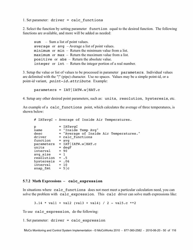
1. Set parameter: driver = calc_functions
2. Select the function by setting parameter function equal to the desired function. The following functions are available, and more will be added as needed:
sum – Sum a list of point values.average or avg – Average a list of point values.minimum or min – Return the minimum value from a list.maximum or max – Return the maximum value from a list.positive or abs – Return the absolute value.integer or int – Return the integer portion of a real number.
3. Setup the value or list of values to be processed in parameter parameters. Individual values are delimited with the "|" (pipe) character. Use no spaces. Values may be a simple point-id, or a point-id variant, point-id.attribute. Example:
parameters = IAT|IATW.w|HAT.c
4. Setup any other desired point parameters, such as: units, resolution, hysteresis, etc.
An example of a calc_functions point, which calculates the average of three temperatures, is shown below:
# IATavgC - Average of Inside Air Temperatures.
p = IATavgCname = "Inside Temp Avg"desc = "Average of Inside Air Temperatures."driver = calc_functionsfunction = avgparameters = IAT|IATW.w|HAT.cunits = degFinterval = 90avg_size = 1resolution = .5hysteresis = .06interval = 10snap_fmt = 5|c
5.7.2 Math Expressions – calc_expression
In situations where calc_functions does not meet meet a particular calculation need, you can solve the problem with calc_expression. This calc driver can solve math expressions like:
3.14 * val1 + val2 (val3 + val4) / 2 - val5.c **2
To use calc_expression, do the following:
1. Set parameter: driver = calc_expression
MoCo Monitoring and Control System Implementation - © MoCoWorks 2010 - 877-360-2582 - 2010-06-20 - 50 of 116

2. Setup the math expression for parameter expression. Values may be a simple point-id, or a point-id variant, point-id.attribute. To prevent the parser from misinterpreting the expression, ALWAYS put a space between a variable and an operator like +, /, *, etc. Most perl math and logic operators may be used, such as: + - / * and **. Although logic operators such as || or && will work, logic calculations may more appropriately performed by calc_ladder_logic in the next section.
Example of a math expression:
expression = "(OAT + OATW)/2 -(IAT + IATW + IATH.c)/3"
4. Setup any other desired point parameters, such as: units, resolution, hysteresis, etc.
An example of a calc_expression point that computes the difference between average outside air temperatures and average indoor air temperatures follows:
# TDiffc - Diff between multiple outside and inside air temps.
p = TDiffcname = "Out/in Temp Diff"desc = "Difference between outside and inside air temps."driver = calc_expressionexpression = "(OAT + OATW)/2 –(IAT + IATW + IATH.c)/3"units = degFinterval = 120avg_size = 3resolution = .5hysteresis = .06snap_fmt = 5|d
While logic evaluations are usually performed by the calc_ladder_logic driver, logic tests such as greater-than or less-than, can also be used in calc_expression. The following would evaluate to a 1 if true or to a zero if false: (temp > 70) Available test operators (like <) are described below with ladder logic.
5.7.3 Ladder Logic – calc_ladder_logic
Ladder logic is a means for making complex logic decisions. Ladder logic will be quite familiar to anyone who has programmed a PLC (Programmable Logic Controller). Ladder logic simulates the wiring of relays, but has been enhanced by various manufacturers to do even more. The various implementations vary.
MoCo's implementation is described below. If you are unfamiliar with ladder logic, tutorials can be found on the web. If you understand symbolic logic but have had no experience with ladder logic or relay wiring, don't panic – ladder logic is easily translated to and from ladder diagrams and symbolic logic expressions (in most cases).
Below is a ladder logic diagram, soon to be demonstrated as an example of point, HeatL:
MoCo Monitoring and Control System Implementation - © MoCoWorks 2010 - 877-360-2582 - 2010-06-20 - 51 of 116
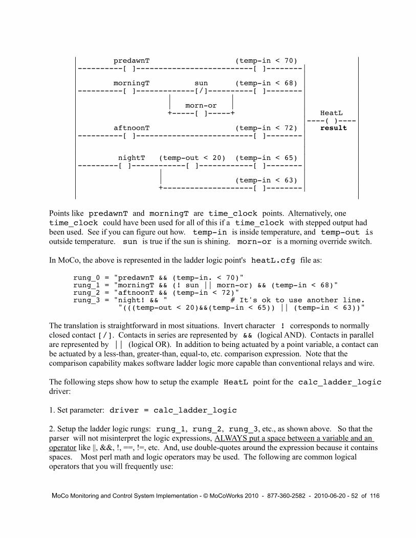
| predawnT (temp-in < 70) ||----------[ ]--------------------------[ ]--------| | | | || morningT sun (temp-in < 68) | ||----------[ ]-------------[/]----------[ ]--------| || | | | || | morn-or | | || +-----[ ]-----+ | HeatL || |----( )----|| aftnoonT (temp-in < 72) | result ||----------[ ]--------------------------[ ]--------| || | || | || nightT (temp-out < 20) (temp-in < 65) | ||---------[ ]------------[ ]------------[ ]--------| || | | || | (temp-in < 63) | || +--------------------[ ]--------| || |
Points like predawnT and morningT are time_clock points. Alternatively, one time_clock could have been used for all of this if a time_clock with stepped output had been used. See if you can figure out how. temp-in is inside temperature, and temp-out is outside temperature. sun is true if the sun is shining. morn-or is a morning override switch.
In MoCo, the above is represented in the ladder logic point's heatL.cfg file as:
rung_0 = "predawnT && (temp-in. < 70)"rung_1 = "morningT && (! sun || morn-or) && (temp-in < 68)"rung_2 = "aftnoonT && (temp-in < 72)"rung_3 = "night! && " # It's ok to use another line. "(((temp-out < 20)&&(temp-in < 65)) || (temp-in < 63))"
The translation is straightforward in most situations. Invert character ! corresponds to normally closed contact [/]. Contacts in series are represented by && (logical AND). Contacts in parallel are represented by || (logical OR). In addition to being actuated by a point variable, a contact can be actuated by a less-than, greater-than, equal-to, etc. comparison expression. Note that the comparison capability makes software ladder logic more capable than conventional relays and wire.
The following steps show how to setup the example HeatL point for the calc_ladder_logic driver:
1. Set parameter: driver = calc_ladder_logic
2. Setup the ladder logic rungs: rung_1, rung_2, rung_3, etc., as shown above. So that the parser will not misinterpret the logic expressions, ALWAYS put a space between a variable and an operator like ||, &&, !, ==, !=, etc. And, use double-quotes around the expression because it contains spaces. Most perl math and logic operators may be used. The following are common logical operators that you will frequently use:
MoCo Monitoring and Control System Implementation - © MoCoWorks 2010 - 877-360-2582 - 2010-06-20 - 52 of 116

For numeric tests:|| Logical OR (two "pipe" characters) Do not use perl's "or" operator.&& Logical AND. Do not use perl's "and" operator.! Inverts the logic of the following variable or parenthesis expression.(x == y) Results true if x equals y.(x != y) Results true if x does not equal y.(x < y) Results true if x less than y.(x > y) Results true if x greater than y.(x <= y) Results true if x less than or equal to y.(x >= y) Results true if x greater than or equal to y.
For text tests (useful tor testing for alarms):(x eq y) Results true if text string x equals text string y.(x ne y) Results true if text string x does not equal text string y.
IMPORTANT: When creating a comparison-test to see if text equals X, use single quotesaround the text character or string only, like 'X'.
3. Setup any other desired point parameters, such as units, force, val_force, etc. Because ladder logic is by default a digital point, parameters like resolution, hysteresis, and avg_size are not relevant. However, a creative individual might solve a difficult problem by forcing a ladder logic point to be an analog point. Do this by setting parameter digital = 0.
You have probably already guessed that the HeatL ladder logic example implements a kind of smart thermostat. The HeatL.cfg file could look like this:
# HeatL - Smart Thermostat to drive a heater.
p = HeatLname = "Smart Thermostat"desc = "Smart Thermostat to drive a heater."driver = calc_ladder_logicrung_1 = "predawnT && (temp-in < 70)"rung_2 = "morningT && (! sun || morn-or) && (temp-in < 68)"rung_3 = "aftnoonT && (temp-in < 72)"rung_4 = "nightT && " # It's ok to use another line. "(((temp-out < 20)&&(temp-in < 65)) || (temp-in < 63))"units = OnOffinterval = 60snap_fmt = 6|c
In the above example, ladder logic “contacts” were used to test for temperature levels. MoCo ladder logic can also test for text. This is useful when testing for a particular alarm condition. If you want to test for alarm conditions, then the conditional logic for the “contact” might look like this:
(MyTemp.alarm eq 'H') # Returns true if alarm H.(MyTemp.alarm ne '-') # Returns true if any active alarm.
When ladder logic is being evaluated, evaluation begins with the lowest available rung, rung_1. It continues to evaluate rungs until a true condition is encountered or until no more rungs, and then it
MoCo Monitoring and Control System Implementation - © MoCoWorks 2010 - 877-360-2582 - 2010-06-20 - 53 of 116

quits. Up to a couple missing rungs are tolerated, but no more than two. The maximum number of rungs is 100.
A non-zero rung-result is considered “true,” and a zero or null is considered “false.” The last true value that is evaluated on the first true rung is returned as the ladder logic value. MoCo leverages this interesting characteristic of the perl language – it returns values other than 0 or 1 if the last true value is something other than 1. Here is an example analog heater control where this characteristic can be quite useful:
rung_1 = “(t33.alarm eq 'H') && -1” # Cannot return 0, so do -1.rung_2 = “(t33 > 72) && 20” # If above 72, output 20% heat.rung_3 = “(t33 > 71) && 60” # If above 71, output 60% heat.rung_4 = “(t33 > 68) && 75” # etc.rung_5 = “(t33 > 65) && 85”rung_6 = 100
The calc_ladder_logic point outputs the percent of power to feed to a heater in this case. The numbers in each rung following the &&'s are actually percentages. Depending upon the temperature, it outputs -1%, 20%, 60%, 75%, or 85%. The output point cannot output anything less than zero (like -1%), so it will output a 0 if there is a “H” alarm. For on/off controlled heaters, the output from this ladder logic could feed a [ ] time_pulser point, which would then feed pulse-width modulated on/off pulses through an output point to a heating element.
5.8 Counters and Stopwatch Timers
Counters: Every point has counter capability. Counters can be used for various purposes, such as:
Counting the number of times a door opens.Counting people or cars.Counting telephone calls.Counting the number of times a motor cycles on and off.Counting valve cycles.
These parameters are relevant to counters:
counter The current count accumulated on the counter.counting Enables counting when set to true.count_up Increments counter on the leading edge of a value going false to to true.count_down Decrements counter on the leading edge of a value going false to to true.reset Resets counter to 0 on the leading edge of value going from false to true.
Parameters counting, count_up, count_down, and reset can be programmatically controlled from any value or expression. Therefore, “!” can be used to invert a controlling value's logic, as needed. If point Switch1 is the value of a switch, Switch1 could be used to start the counter, and then !Switch1 could be used to stop and reset the counter.
Stopwatch timers: Every point has stopwatch timer capability. Although one point can use another's
MoCo Monitoring and Control System Implementation - © MoCoWorks 2010 - 877-360-2582 - 2010-06-20 - 54 of 116

timer, accuracy is much higher if a calculation point uses its own timer. In this case the error is less than 10 microseconds. When using timers on other points, the different intervals make timing somewhat less accurate, but disassociated timers are usually good enough for controlling scenes or staging machinery. Timers can be used for various purposes, including:
Calculating time per day (or unit time) that a point is on or off.Calculating duty cycle.Creating delays.Staging scenes, or sequencing events.
These parameters are relevant to all timers:
timer The current time accumulated on the timer. Usually read-only.start Starts the timer on the leading edge of a value going from false to to true.stop Stops the timer on the leading edge of a value going from false to to true.reset Resets the timer to zero on the leading edge of a value going from false to true.
These read-only parameters are specific to calc points:
time_intv Precise time in seconds for the previous interval.time_now Precise system time in seconds when the calculation is being performed.time_prev Precise system time in seconds when the previous calculation was performed.
Parameters start, stop, and reset can be programatically controlled from any value or expression. Therefore, “!” can be used to invert a controlling value's logic, as needed. If point Start1 is the value of a switch, Start1 could be used to start the timer, and then !Start1 could be used to stop and reset the timer. The time_ parameters are helpful for performing accurate time-related calculations like duty cycle.
When combined with ladder logic, timers are particularly handy for sequencing a scene or sequentially staging machinery. In such applications, point IJK ladder logic would contain tests for a set of contacts like: “(IJK.timer > 123)” This is a test to see if the point's timer has gone above 123 seconds.
The timer variable would normally be treated as a read-only variable. However, there are occasions where altering it can prevent a good deal of ladder logic complexity. Ladder logic can sometimes become complex – just to work around system startup and initialization issues. In some cases, initializing a counter to a high value in the .cfg file can remove the need for convoluted ladder logic whose sole purpose is to assure a clean startup.
Suggestion: When creating ladder logic solutions, don't be afraid to think outside the box.
5.9 Implementing Scenes
The “scene” is a an important concept in home automation. The term “scene” typically refers to a
MoCo Monitoring and Control System Implementation - © MoCoWorks 2010 - 877-360-2582 - 2010-06-20 - 55 of 116

lighting environment for a room or set of rooms. It includes controllable lights that are set on or off. More sophisticated scenes include the dim level and the rate at which lighting turns on or off. Other aspects of the environment, such as music or home theater, can be setup, as well. Home automation systems often activate a scene at a particular time of day or after an event.
Because scenes are so important in home automation, home automation software has special setup screens and files that define scenes. Although MoCo is a more general-purpose monitoring and control system, its basic building blocks enable a person to configure scenes in the same spirit as a specialized home automation system.
Regardless of the system and its user interface, the concepts are identical: A set of devices are controlled as a function of time or events. With MoCo, scenes can be setup with time clock points and with ladder ladder logic.
Probably the simplest implementation would be to setup a time_clock point for each scene. The time clock would turn a static scene on or off at different times of day, which may be different on weekends, etc. Using the time clock's val_force and force parameters, other events can override the time clock's normal sequence. In the simplest case, a switch input point could drive the time clock's val_force override. Sophisticated control logic is possible by feeding val_force from a calc_ladder_logic point, or simply by directly feeding val_force with an expression like “(LiteLevel < 20)”.
Remember that points can send their result to multiple output points. Therefore, controlling multiple lights from a single time clock is easy. As with the time clock point, each individual output point also has the capability to have its output device be overridden via val_force and force controls. This becomes useful in home automation when there is a need to override default scene settings with an external X10 or Insteon switch.
Another scheme for implementing a sequence of dynamic scenes is to implement a single time clock point that drives multiple calc_ladder_logic points, each of which drives one or more output points. Time clocks are not limited to producing just 0 or 1. A single time clock can output any numeric value for any of a multiplicity of events. A time clock could be setup to produce a stepped result of 1, 2, 3, 4 … representing phases of a scene.
The time clock's “phase numbers” could then feed to each ladder logic's enable_out parameter as part of an expression, like: enable_out = “(SceneX == 3)”. The expression in quotes evaluates to 1 if the result from time clock SceneX equals 3; otherwise, the expression evaluates to 0.
This enables each ladder logic point to send signals to output points only when the appropriate phase is active. Note also that enable_out prevents do_next output-triggers from reaching output points, only. With this technique, output points will only receive signals from a ladder logic point when the point is selected by its designated phase number. By design, the other ladder logic points will just have to twiddle their thumbs until it is their turn to send outputs.
If ignored and unused, enable_out defaults to “true”. In other words, outputs are enabled by default. The enable_out feature may seem uninteresting or confusing to early implementers.
MoCo Monitoring and Control System Implementation - © MoCoWorks 2010 - 877-360-2582 - 2010-06-20 - 56 of 116

But please remember the capability – it becomes quite useful in sophisticated systems.
While the afore mentioned time clock solution works well for a fixed schedule, there are situations when the “scene” (or staging sequence) needs to be triggered at random times. For example, when a person walks into a room and flicks a light switch, the scene lights would come up in a timed sequence. In an industrial environment, heavy machinery starts up in a staged sequence – perhaps for the purpose of preventing power surges.
By using a point's timer, ladder logic points can solve the problem. The timer in the first ladder logic point would be triggered via the start parameter from an input point driven from a push button. The first ladder logic point would turn on an outpoint immediately. A second ladder logic point would turn on after 30 seconds using a test like: “(XYZ.timer > 30)”. A third device could be turned on at 90 seconds in the same manner. A power-down sequence can be implemented using the same techniques, and possibly by using the same ladder log points with additional rungs. See the details in the Example Task Snippets chapter.
Although using industrial-style logic to create scenes will be unfamiliar to most homeowners, industrial logic does have the advantage of being somewhat more flexible than a pre-defined scene mechanism. In an industrial environment, support personel are familiar with ladder logic – so familiar, it is said, that control engineers and technicians can read ladder logic better than their native language.
MoCo Monitoring and Control System Implementation - © MoCoWorks 2010 - 877-360-2582 - 2010-06-20 - 57 of 116

6. Alarms
6.1 Alarms Overview
Alarms are the means by which MoCo notifies human operators that a point needs attention. Typically, a point needs attention when its value becomes too high or too low. In the real world, however, it is not that simple. System owners may desire warning-level alarms that correspond to warning-high, warning-low, too-high, and too-low. They may be interested in an abnormal rate-of-change. They may want the extreme alarms to be latched, and the warning alarms to be non-latched – a variety of possibilities for different situations.
A latch alarm is an alarm that remains stuck on, once it has been triggered. Only an operator can acknowledge (thereby unlatching) the alarm. Non-latch alarms, on the other hand, go away as soon as the triggering condition goes away.
A person can acknowledge a latched alarm with program mocom. Enter mocom -h to view a help screen. mocom expects a person to enter his or her handle – initials, or other ID. In order to use mocom, a user must have a file setup called moco-id.usr, where id is the user's initials. At this time, there are minimal requirements for the contents of this file. The only required entry is the user's full name, like: my_name = “John Doe”. MoCo records all mocom commands in the moco.log file, along with the operator's initials.
MoCo allows up to 26 general-purpose alarms to be configured per point. The 26 alarms correspond to the 26 letters of the English alphabet. In addition, there are two special alarms. “?” is a non-latch alarm that appears whenever data is unavailable, due to network problems or to a sensor that has died. It goes away as soon as the problem is fixed. “!” is a manual alarm that can be triggered by a user from mocom. It is a latch alarm that requires acknowledgment via mocom.
Alarms are only functional for a point if they are enabled in the point's .cfg file with the alarms parameter, which contains a list of alarms. However, alarms can be limited to the bad-data and manual “!” alarms by setting the alarms parameter thusly: alarms = “!”
With driver input_alarm_tally, one or more special alarm points can be created that display the number of active triggered alarms. The display format looks like 2.04, where 2 is the number of active unacknowledged (latched) alarms, and 4 is the total number of active (triggered) alarms. The alarm point is a digital input point that behaves like any other digital input point. You can even configure an alarm for the alarm point.
input_alarm_tally can be configured to cover one of three possible scopes. Set parameter scope to 0 to tally all alarms in the handler. Set scope to 1 to cover the node (the computer). Set scope to 2 to cover all alarms on a MoCo system, world wide. The default scope is 0.
6.2 Configuring Alarms
MoCo Monitoring and Control System Implementation - © MoCoWorks 2010 - 877-360-2582 - 2010-06-20 - 58 of 116

Alarms are configured in the point's .cfg file. Here is a short example:
alarms = !|H|L # Enable alarms and set priority.alarm_H = "95|U|.2||c|Glass-room too hot!"alarm_L = "32|D|.2||c|Glass-room freezing!"
The alarms parameter enables alarms and lists possible alarms in order of priority, highest priority to lowest priority. The manual alarm “!” is always the highest priority alarm. If alarms are enabled “!” must be the first alarm character in the list. Threshold-style alarm characters follow the “!” character. They are delimited with the “|” (pipe) character without spaces.
The alarm character can be a-z for non-latch alarms, and A-Z for latch alarms. Choose a meaningful character, like H for High alarm , L for Low alarm, w for too Warm, and c for too Cool. The choice is yours.
The individual alarms are are defined in parameters with names like: alarm_H, alarm_L, alarm_w, alarm_c, etc. Note that the alarm characters are case-sensitive; they must match the character in the alarms list. Each alarm definition parameter has up to six fields, separated by the “|” pipe character. If a field is not specified, a default is used. Here is a summary of the six fields:
1. Threshold value for the alarm. Required field.
2. The transition direction that will trigger the alarm: U for Up and D for Down.U is default.
3. Hysteresis value. Hysteresis can prevent nuisance alarm transitions. With hysteresis, thealarm still triggers at the threshold value, but grants some slack before releasing. 0 is default.
4. Rate-of-change per minute. If the value-threshold has been crossed and if the rate-of-change threshold has been exceeded, then the alarm becomes active. The rate-of-changeparameter would normally be negative for down-direction value thresholds. The rate-of-change test is not performed if the field is null (empty).
5. Point's value variant-id. c for point.c, w for point.w, h forpoint.h, etc. Variant c, the clean value, is default.
6. An optional, very short message to be displayed in reports when there is an active alarm.
Remember to surround the parameter in double-quotes if there are any spaces in the text string.
6.3 Handling Alarms
MoCo software attempts to provide convenient tools for the managing of alarms. It does so by providing useful status data, alarm counts, and shell commands that can be executed upon alarm events.
MoCo Monitoring and Control System Implementation - © MoCoWorks 2010 - 877-360-2582 - 2010-06-20 - 59 of 116

Alarm information is written to database tables history and snapshot. The alarm character, events, event-times, and remark are written to both. An alarm character is not displayed if alarms are not enabled for the point. If an alarm is enabled but not triggered, a “-”character is displayed. When an alarm event occurs, a remark is generated that includes the alarm character, the threshold value, and the pre-defined short text string. This information is displayed in MoCo reports.
For history data, the alarm character is encapsulated within the history table's status field. In mocor history reports, it is displayed with the remark.
For status data, the alarm character is encapsulated within the snapshot table's alarm field. In mocos status reports, it is displayed to the far left of the line: upper case for not acknowledged, or lower case for acknowledged. The configured alarm character is displayed at the front of the remark. An unacknowledged alarm displays as shown below. The “10m” to the left of “ALARM-L” shows that 10 minutes have passed since the alarm triggered. The “65” to the right is the alarm threshold.
L IATB 64.17 64.2 degF 09:26 10m ALARM-L 65 Brewery, cool!
For latched alarms, a person may clear (acknowledge) the alarm when it is noticed, or after the problem is fixed. The procedure depends upon department policy. After being acknowledged, the above alarm would look like this:
h IATB 64.17 64.2 degF 11:25 23m ACK-h rw Cool is nice.
Communication program mocom is used to acknowledge an alarm. Note that when using mocom, point-ids may be entered in all lower-case; and that the point-id can contain wild-card characters, allowing a user to acknowledge multiple commands with one command. When using wild-card characters, remember to place double-quotes around the point-id argument. To acknowledge an alarm, or alarms, enter a command that looks like one of the examples:
mocom user-id point-id - # Usage.mocom rw IAT - # Actual example.mocom rw iat - # Lower-case works, too.mocom rw IATB,IATH,IATW - # Ack multiple alarms.mcocm rw “IAT*” - # Wildcards.
mocom user-id point-id - [remark] # Usage, more verbose.mocom rw iat - got it, george! # Actual wordy example.
In environments with multiple people on a maintenance team, one person might notify the others of a problem by triggering the manual alarm for a point. To set the special manual “!” alarm, enter:
mocom user-id point-id ! remark # Usage.mocom bo iat ! Morning George # Actual example.
mocom can also be used to temporarily override alarm thresholds while mocod daemons are running. The following command overrides the configured threshold with a new value of 85 for point IAT. The mocom command changes parameter IATW.alarm_to_x to value 85. The “to” in the parameter name stands for “Threshold Override”. The alarm character is always lower
MoCo Monitoring and Control System Implementation - © MoCoWorks 2010 - 877-360-2582 - 2010-06-20 - 60 of 116

case so that typing will be easier and so a person doesn't have to remember if the alarm is latching or non-latching. alarm_to_x does not alter the original value – it just temporarily overrides it.
mocom gw IATW alarm_to_x 85
When an override is in effect, it is displayed in history reports and status reports. This is what it looks like in a status report. 80 is the configured alarm threshold; 85 is the threshold override:
X IATB 85.56 86 degF 09:36 15m ALARM-X 80to85 Problem.
These mocom commands simply change a cfg variable in the proper mocod handler. Run a similar command to remove the alarm threshold override. Set the override to null like this:
mocom jc IATW C alarm_to_x “”
The string of alarm configuration parameters for an alarm can be changed on the fly by using mocom to alter the alarm_x parameter. Ordinarily, a user would not temporarily alter the alarm-definition string because he might forget the original value. But, for the record, here's how it is done:
mocom bc IATB alarm_H “71|U|1||c|Brewery, too hot!"
Those with little or no command-line experience might say, “Gee, this seems cryptic and old fashioned.” They are probably right. But if versatility and speed of acknowledging or altering an alarm are worthy considerations, the command line wins, especially considering the time it takes to navigate to an applicable GUI screen. Undoubtedly, someone (maybe MoCoWorks) will create a GUI interface to overlay mocom. Until then, mocom rules by default.
mocom also has the ability to permanently change alarm parameters (or other parameters) in a point's .cfg f ile, and then to upload the modified file to a running mocod handler. This is handy in 7x24 environments.
If you forget mocom's command syntax, just request command help: mocom -h
6.4 Alarms Triggering Shell Commands
Except, perhaps, in large enterprise factory situations, most system managers do not stare at a terminal all day waiting for alarms. In systems of any size, it is more convenient to receive a phone text message and/or email when a serious alarm occurs. MoCo enables this functionality with shell commands.
Utility programs for network file copying and for sending messages differ from system to system, MoCo does not attempt to anticipate and handle every desired external action. Instead, MoCo provides a means to trigger a program or shell script. The program or shell script can be setup to do almost anything that can be done on a computer: send a phone text message, send an email, transfer a file to another system, update a web site, pop up a warning display, display a mocos status report, feed a large ticker display panel, etc.
MoCo Monitoring and Control System Implementation - © MoCoWorks 2010 - 877-360-2582 - 2010-06-20 - 61 of 116

For example, suppose that an alarm triggers because a chiller temperature has gone too high, or because the chiller has begun drawing higher-than-normal current. The alarm could trigger command mocos “Chil*”. This would display current status for all chiller-related temperatures, pressures, and power consumption. In this simple example, the status screen would display within the same window that mocod is operating within.
A more sophisticated script could cause the status screen to be displayed on terminals around the plant. Or, a copy of the status report could be emailed to the maintenance team whenever a serious chiller alarm triggers.
A shell command can be setup for each of a point's 28 different alarms. And the trigger can occur on new-alarm, alarm-acknowledge, and alarm-clear – up to 58 possibilities for each point. Here are some examples of a point's .cfg file alarm commands:
cmd_a_H # Alarm “H”, for example, has been triggered & latched. # (Use any alarm id, A-Z.)
# If a no-latch alarm, do not use cmd_a_H. Instead # use cmd_a_h to trigger a shell command when the # alarm has gone active and auto-acknowledged.
cmd_a_h # Alarm “H” has been acknowledged, now displayed as “h”.
cmd_a_bd # A “?” bad-data alarm has triggered. It does not latch.
cmd_a_ma # The “!” manual alarm has been triggered and latched.
cmd_a_mc # The “!” manual alarm has been cleared.
cmd_a_ac # All alarms are now clear.
To trigger a command from one of the above, set the parameter to be the desired shell command. For example, to send a text message when a water pipe is about to freeze, setup a command similar to the following. The “F” alarm is setup to indicate a freeze alarm. Shell script send-text-msg.sh needs to contain the actual commands for sending out messages to various people. The .p and .alarm variables in curly braces are passed to the shell script along with the text that follows:
cmd_a_F = “send-text-msg.sh {.p} {.alarm} 'Pipe close to freeze!'”
Note in the above command that the .p and .alarm variables do not include a point-id before the dot. If the point-id is missing, MoCo assumes that the point-id is the same as point-id of the variable that is being alarmed. If the variables are for a different point, then include the point-id.
An alarm can easily be setup to drive an annunciator directly from MoCo. One way is to setup a calc_ladder_logic point to look for one or more alarms. A ladder logic rung could be rung_1 = “(pipe.alarm eq 'F')”. The ladder logic output would feed the digital output point that controls the annunciator. If there are multiple annunciators all over the plant, the ladder logic result can be sent to multiple output points.
MoCo Monitoring and Control System Implementation - © MoCoWorks 2010 - 877-360-2582 - 2010-06-20 - 62 of 116

Another way to drive a general-purpose alarm light would be to feed the output of an input_alarm_tally point to a digital output. In this case, the alarm light would turn on whenever any alarms occur within the alarm point's scope. By setting a couple of point parameters, the light could be caused to shine only for unacknowledged alarms.
MoCo Monitoring and Control System Implementation - © MoCoWorks 2010 - 877-360-2582 - 2010-06-20 - 63 of 116

7. Reports
7.1 Reports Overview
Two MoCo report programs are included with MoCo at this time. mocos is a general purpose status reporting program. mocor is a general purpose history reporting program. Both produce textural reports. They run on all MoCo supported platforms, and they can be run on remote computers using terminal communications software like telnet or ssh.
Wildcard capability for the optional point argument enables the scope of reports to be constrained to a subset of points. When wildcard characters are used, the argument must be quoted to prevent the operating system from attempting to interpret the wildcard characters. The following wildcard characters (same as for Linux and similar to Windows) are supported by MoCo reports:
* Zero or more characters? Exactly one character[abcde] Exactly one character listed[a-e] Exactly one character in the given range[!abcde] Any character that is not listed[!a-e] Any character that is not in the given range
The search-mask is case-insensitive. Multiple point-ids or point-id masks can be used, like:
“hvact*,hvacc*,lvrmtw,restb”
While mocos and mocor can meet the basic needs for reporting, they lack the color and class of a graphic plot. Graphic reports have not yet been formally adapted to MoCo. However, MoCo report programs can optionally produce a format like database output that can be processed downstream to generate a GUI result. Furthermore, MoCo historic data is stored in a conventional SQL database. Open source and commercial software is available that can create reports from SQL databases – it just takes development time, and possibly money.
7.2 Status Reports
mocos is MoCo's basic status reporting program. The data for the report is obtained from the snapshot table in MoCo's SQL database. The snapshot table includes all points from all integrated MoCo systems. This may include one computer, several computers on a local network, or a world-wide system of computers.
mocos reports the current status of points, aligned in the following columns: alarm status, point-id, current working value (without override), the last history value written to the history table, the time when the last history value was written, the age of the last remark being displayed, and the last remark, itself. Concise override and alarm information is inserted before the remark, if present.
MoCo Monitoring and Control System Implementation - © MoCoWorks 2010 - 877-360-2582 - 2010-06-20 - 64 of 116

On a small system of about a dozen points, mocos will produce a report that looks similar to the following. Just run the command: mocos
ALARM VAL VAL-HIST TIME REM-AGE REMARK POINT OutFile 1 1 13:10 Alarms 1.02 1.02 cnt 13:10 Outside ........................................! OAT 43.7 44 degF 13:10 31 40 ALARM-! rw Fixing it. OATW 35.3 35 degF 13:09 WGusW 14 14 mph 13:09 - WSpdW 4 4 mph 13:09 WDirW 56.5 30 deg 13:09 HumW 62 65 % 13:09 DewPW 24.5 24 degF 13:09 BaroW 29.972 29.98 in 13:09 Inside ........................................L IATB 55.8 56 degF 13:10 28 ALARM-L Brewery cold!h IATH 77.52 77.5 degF 13:10 17 ACK-L rw HVAC room hot! IATset 70 70 degF 13:09
The remark-line to the far right is for displaying recent activity, such as an override, alarm, or the last action triggered by the mocom program. In the above example, the OAT point has an override of 40 degF. It also has an active, unacknowledged manual alarm that was set by user “rw”. User rw is apparently fixing a problem with the sensor, and set the override to 40 while he works on it. Point IATB has an unacknowledged “L” alarm. “Brewery cold!” is the alarm remark text. Point IATH has an acknowledged “H” alarm that was acknowledged by user rw.
For systems with dozens or hundreds of points, people who run the status report are more likely to be interested in a small subset of points. Therefore, they will run the report with a wildcard pattern, or a list of desired points. Here are some examples:
mocos barow # Just point BaroW.mocos IAT,oat # Just points IAT and OAT.mocos “I*” # All points that begin with I.mocos “I*,O*” # All points that begin with I or O.mocos “?T*” # Any 1st, T for 2nd char, any trailing charsmocos “[0-9]*” # First character must be 0 to 9.
Note that quotes must be used when wild-card characters are present. This is necessary because the wild-card characters have special meaning to the operating system. They must be quoted to keep the operating system from being confused.
The mocos display will refresh itself every 8 seconds if you enter the following command, which is very handy for keeping a current display on the screen without repeatedly typing on the keyboard.
mocos 8
mocos has a number of other options, such as being able to display only points that are in override or alarm. With “s”and “S” options, it can also display “stealth” points that are normally hidden from view. The options are displayed in the mocos -h help screen:
MoCo Monitoring and Control System Implementation - © MoCoWorks 2010 - 877-360-2582 - 2010-06-20 - 65 of 116

This program reports status of IO points.Usage: mocos [-switches] [dislpay-intv] [report-file|point-mask]
Switches: (following single-chars with leading hyphen before the string)
-h Display help. Default scope: Every point specified by rpt-file or point-mask. -a Report all points that are in alarm state. -A Report all points that have defined alarms. -o Report all points that have overrides. -r Report all points with any kind of remark. -u Report all points with anything unusual. -s Only show stealth points. -S Also show stealth points.
Switches and other arguments may be in any order.A numeric (like 10) is the interval between repeated displays.A non-numeric is first tried as the name of a report file (.rpt file).If the file does not exist, it is treated as a point-mask. Examples:
mocos -h (Help.) mocos 10 (Display all points, refresh every 10 sec.) mocos -ar "I*,O*" (Alarms & remarks, ids starting with I or O.) mocos -o (Display all points with overrides.) mocos IAT,OAT (Display points IAT and OAT.) mocos inside (Display report defined by file inside.rpt.) QUOTE ANY PARMS ON COMMAND LINE IF THEY CONTAIN SHELL CHARS *?+|<> etc.
The example report shown at the beginning of this section has some, but not much, formatting. Formatting in that report was limited to section lines beginning with “Inside” and “Outside”. The order of the points was in a predefined sorted order, as specified by the person who configured the points.
This formatting is controlled by the snap_fmt line in each point's .cfg file. The first point in each section has a relatively long snap_fmt line that looks like this.
snap_fmt = "2|a|Inside ........................................"
The lines that follow in the same section look like this: snap_fmt = 2|b
The snap_fmt line has up to three fields, each separated with the “|” (pipe) character. The first field is a major sort field for the sections, the second is a minor sort field, and the third is the optional section header. This scheme enables a person to specify sort order and to insert some headers.
[ ] Report definition files: A system manager or user can embellish reports with custom header and footer by setting up .rpt files. To see how, have a look at the sample.rpt files that is included with the MoCo software package. The report can be setup to run exactly as specified in the .rpt file. However, if the end user wants to override point-id scope parameters or select a specific kind of report (overrides, alarms, etc.), then custom scope and switches can be entered on the command line when mocos is run.
Although the need to change defaults on a new system is unlikely, be aware that some mocos
MoCo Monitoring and Control System Implementation - © MoCoWorks 2010 - 877-360-2582 - 2010-06-20 - 66 of 116

defaults can be fine-tuned by entering new values in the moco.ini file.
Most of a program's informative messages, prompts, error-messages, and column headers can be customized by creating a mocor.lcl localization file for the program.
7.3 History Reports
mocor is MoCo's basic history reporting program. The data for the report is obtained from the history table in MoCo's SQL database. The history table includes history from all points from all integrated MoCo systems. This may include one computer, several computers on a local network, or a world-wide system of computers.
mocor reports the history of selected point values, with selected characteristics, over a specified period of time. The columns differ, depending upon the kind of report specified. However they usually include the following information, one way or another: date/time, history value, units, remark, and override and alarm information.
To run a default report that covers the last four hours without passing through the edit screen, enter:
mocor
The report will look something like this segment, except longer:
10-02-2517:01 70 degF IATset InsideTemp Setpoint 17:01 22 mph WGusW Wind Gusts WX 17:01 4 OutFile 17:02 66 degF IATB Brewery Air Temp 17:03 65 degF IATB Brewery Air Temp 17:05 0 OnOff TClock1 Time Clock 1 17:05 0 OnOff TClock1o Time Clock 1 Out 17:05 1 OnOff Tc1offo Off-pulse fr TClock1 17:05 43 degF OAT Outside Air Temp 17:06 0 OnOff Tc1offo Off-pulse fr TClock1 17:07 75 % HumW Humidity WX 17:08 0 mph WSpdW Wind Speed WX 17:10 1 OnOff TClock1t Time Clock 1 17:10 1 OnOff TClock1o Time Clock 1 Out 17:10 1 OnOff Tc1ono On-pulse fr TClock1 17:10 61 F GATW GlassRm Air Temp WX _ 17:11 0 OnOff Tc1ono On-pulse fr TClock1 17:11 30.08 in BaroW Baro Pressure WX
Report options are similar to mocos, except there are more of them, and mocor provides the benefit of an edit screen. Consequently, mocor offers three ways to enter report parameters: the command-line, an optional edit screen, or via .rpt files. As with other MoCo programs, enter mocor -h to view a help screen that explains the run-parameters. Here's what you get:
mocor.pl reports history of IO points. To display help, enter: mocor.pl -h
MoCo Monitoring and Control System Implementation - © MoCoWorks 2010 - 877-360-2582 - 2010-06-20 - 67 of 116
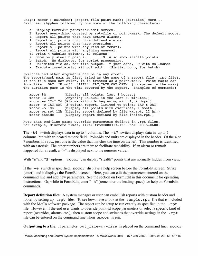
Usage: mocor [-switches] [report-file|point-mask] [duration] more...Switches: (hyphen followed by one more of the following characters)
e Display FormEdit parameter-edit screen. E Report everything covered by rpt-file or point-mask. The default scope. a Report all points that have active alarms. A Report all points that have defined alarms. o Report all points that have overrides. r Report all points with any kind of remark. u Report all points with anything unusual. t4 Print 4 tabular columns, t7 columns. s Show only stealth points. S Also show stealth points. b Batch. No dialogue, for script processing. f Delimited fields, for file output. f just data, F with col-names x Execute immediately, without edit. (Similar to b, for batch)
Switches and other arguments can be in any order.The report/mask parm is first tried as the name of a report file (.rpt file).If the file does not exist, it is treated as a point-mask. Point masks canlook like: OAT "Wind?" "IAT*" IAT,IATW,OAT,OATW (no spaces in the mask)The duration parm is the time covered by the report. Examples of commands:
mocor 8h (Display all points, last 8 hours.) mocor -u 30m (Anything unusual in the last 30 minutes.) mocor -a "I*" 2d (Alarms with ids beginning with I, 2 days.) mocor -c IAT,OAT (2-column report, limited to points IAT & OAT) mocor -o 1mo (Display all points with overrides, 1 month.) mocor wx.rpt 12h (Display report defined by file wx.rpt, 12 hr.) mocor inside (Display report defined by file inside.rpt.)
Note that cmd-line parms override parameters defined in .rpt files.For example, discrete times, like: from=080313-1230 to=080315-0600.
The -t4 switch displays data in up to 4 columns. The -t7 switch displays data in up to 7 columns, but with truncated remark field. Point-ids and units are displayed in the header. Of the 4 or 7 numbers in a row, just one is the value that matches the time on the left. This number is identified with an asterisk. The other numbers are there to facilitate readability. If an alarm or remark happened for a result, a “>” is displayed next to the numeric value.
With “s”and “S” options, mocor can display “stealth” points that are normally hidden from view.
If the -e switch is specified, mocor displays a help screen before the FormEdit screen. Strike [enter], and it displays the FormEdit screen. Here, you can edit the parameters entered on the command line and add new parameters. See the section on FormEdit in this document for operating instructions. Or, while in FormEdit, enter “ h” (remember the leading space) for help on FormEdit commands.
Report definition files: A system manager or user can embellish reports with custom header and footer by setting up .rpt files. To see how, have a look at the sample.rpt file that is included with the MoCo software package. The report can be setup to run exactly as specified in the .rpt file. However, if the end user wants to override point-id scope parameters or select a specific kind of report (overrides, alarms, etc.), then custom scope and switches that override settings in the .rpt file can be entered on the command line when mocos is run.
Outputting to a file: If parameter out_file=my-file is placed on the command line, mocor
MoCo Monitoring and Control System Implementation - © MoCoWorks 2010 - 877-360-2582 - 2010-06-20 - 68 of 116

will output to the specified file. Set switch -f to output delimited-field data records, suitable for sending to a database or spreadsheet. Set switch -F to have column names as the first record. The standard column names for the -F option are as follows:
datetime|point|value|units|alarm|override|remark|
If different names are needed, create a header in a .rpt file. Perhaps you would rather have a comma as a delimiter? Then enter fld_sep=, (with no spaces) on the command line along with everything else. mocor uses an ISO-8601 date format as the default for this report, like: 2010-02-26 17:05:33. If a different date format is desired, you can change it from date_fmt=”$y4-$mo-$md $hr:$mi:$se” to a preferred format. These parameters can be changed temporarily via the command-line, or more permanently by placing them in the moco.ini file or [ ] a .rpt file.
Use the -b switch to suppress extra output for “batch file” situations. A typical command to silently output delimited data to a file looks like this:
mocor -bF “I*” 24h out_file=inside-points.dat
Although the need to change defaults on a beginner's system is unlikely, be aware that defaults can be changed by entering new values in the moco.ini file.
When changing default parameters, it is important to understand that the precedence for selecting run-parameters is versatile, and therefore complex. mocor gets its final run-parameters according to the following precedence, from highest to lowest: edit screen, command line, .rpt file, .ini file, and lastly, mocor's internal defaults.
Most messages and column headers can be customized by creating a mocos.lcl localization file for the program.
7.4 Shell Scripts for Common Reports
With wild-cards and .rpt files, a report covering just about any scope can be specified. But what if a person needs to run a report frequently without having to type more than a few characters? A one-line script may be the answer.
In the example below, the user enters “pool” to get a history report on his solar pool-system temperatures. The pool script contains just one line:
mocor -t7 waterTemp,hotTemp,retnTemp,motorOn,panelTemp 8h
When creating a script that contains a one-liner like this, remember on unix-style systems (which includes Mac) to change file-permissions so that the file will be executable.
7.5 Graphic Web Status Reports
MoCo Monitoring and Control System Implementation - © MoCoWorks 2010 - 877-360-2582 - 2010-06-20 - 69 of 116

Customers often desire graphic status reports that have diagrams with pictures with numbers and colors that change in real time. Because such displays are different for each application, no monitoring and control system can provide graphic displays that are perfect for every customer. Instead, the systems often provide tools that enable a user or developer to build the desired display.
Web-based GUI solutions are portable and viewable world-wide. Platform-based GUI interfaces are, in practice, specific to the operating system. They require complex linkage, which complicates installation and maintenance. Viewing is limited to the platform on which they reside. Consequently, users are encouraged to develop web-based user interfaces that utilize html or php code that works reliably on conventional web servers and browsers.
A variety of web servers are available for the common operating systems. The Apache web server is free and a world-wide standard. It is already installed on Mac computers. However, it must be enabled in System Preferences, and php must be enabled by uncommenting a line in the /private/etc/apache2.conf file. Apache with php can be downloaded to Windows from http://www.apache.org. Apache with php capability is already loaded on most Linux systems.
Once the web server with php has been enabled, the system developer creates conventional web pages. The web pages may be constructed of php code, which has the ability to directly access data from MoCo reports or the MoCo database. Or, the page may be coded as html templates that are repeatedly stuffed with real-time data.
With driver output_file, MoCo provides a means for stuffing templates with real-time data. The result can be either used directly as a text-style file for display, or an html or php file that can be displayed on the web.
This feature enables the creation of animated screens, where text and point values change in real time. Real-time data fields can be individually left-justified centered, or right-justified. Changeable labels can be displayed just like real-time numeric data. For html web pages, MoCo's basic features additionally enable a developer to implement real-time changes of web page parameters such as color, font-style, object or text position, etc.
The steps for implementing a template follow:
1. Create a template file. Start with a simple one that has several points. The template can be the beginnings of an html web page, or just plain text. Instead of including static numbers in the file (which, of course, would be old history in seconds or minutes), the variable name of each desired point is included within the text, encoded as follows:
Weather Inside Temperatures F ----------------------- ----------------------- | Temperature:}}OutsTW} | | Living Room:}}LvrmTW} | | Humidity:}}}}}}}HumW} | | Brew Area:}}}}RestTB} | | Dew Point:}}}}}DewPW} | | Big Cooler:}}}RestTC} | | Barometer:}}}}}BaroW} | | Ferm Room:}}}}FermTA} | | Wind Speed:}}}}WSpdW} | | Garage/Hvac:}HvacTAi} | | Wind Gusts:}}}}WGusW} | | Glass Room:}}}GlasTW} | | Wind Direction:}}}}7} | | |
MoCo Monitoring and Control System Implementation - © MoCoWorks 2010 - 877-360-2582 - 2010-06-20 - 70 of 116
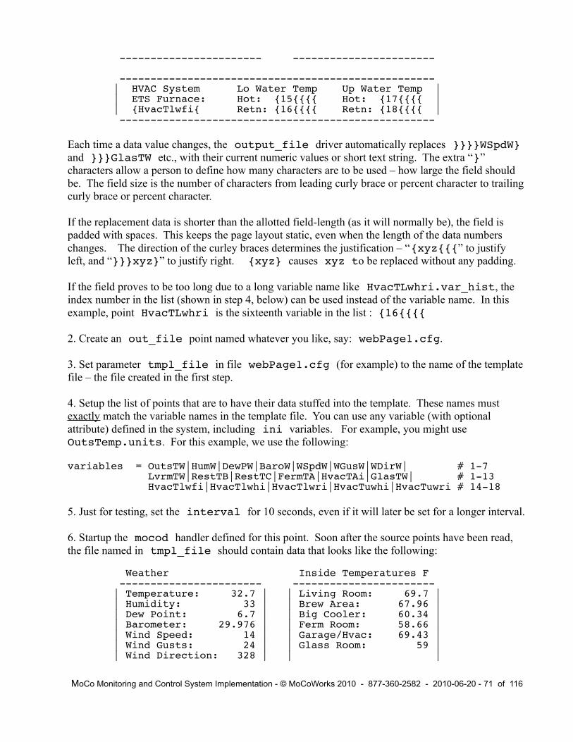
----------------------- -----------------------
--------------------------------------------------- | HVAC System Lo Water Temp Up Water Temp | | ETS Furnace: Hot: {15{{{{ Hot: {17{{{{ | | {HvacTlwfi{ Retn: {16{{{{ Retn: {18{{{{ | ---------------------------------------------------
Each time a data value changes, the output_file driver automatically replaces }}}}WSpdW} and }}}GlasTW etc., with their current numeric values or short text string. The extra “}” characters allow a person to define how many characters are to be used – how large the field should be. The field size is the number of characters from leading curly brace or percent character to trailing curly brace or percent character.
If the replacement data is shorter than the allotted field-length (as it will normally be), the field is padded with spaces. This keeps the page layout static, even when the length of the data numbers changes. The direction of the curley braces determines the justification – “{xyz{{{” to justify left, and “}}}xyz}” to justify right. {xyz} causes xyz to be replaced without any padding.
If the field proves to be too long due to a long variable name like HvacTLwhri.var_hist, the index number in the list (shown in step 4, below) can be used instead of the variable name. In this example, point HvacTLwhri is the sixteenth variable in the list : {16{{{{
2. Create an out_file point named whatever you like, say: webPage1.cfg.
3. Set parameter tmpl_file in file webPage1.cfg (for example) to the name of the template file – the file created in the first step.
4. Setup the list of points that are to have their data stuffed into the template. These names must exactly match the variable names in the template file. You can use any variable (with optional attribute) defined in the system, including ini variables. For example, you might use OutsTemp.units. For this example, we use the following:
variables = OutsTW|HumW|DewPW|BaroW|WSpdW|WGusW|WDirW| # 1-7 LvrmTW|RestTB|RestTC|FermTA|HvacTAi|GlasTW| # 1-13 HvacTlwfi|HvacTlwhi|HvacTlwri|HvacTuwhi|HvacTuwri # 14-18
5. Just for testing, set the interval for 10 seconds, even if it will later be set for a longer interval.
6. Startup the mocod handler defined for this point. Soon after the source points have been read,the file named in tmpl_file should contain data that looks like the following:
Weather Inside Temperatures F ----------------------- ----------------------- | Temperature: 32.7 | | Living Room: 69.7 | | Humidity: 33 | | Brew Area: 67.96 | | Dew Point: 6.7 | | Big Cooler: 60.34 | | Barometer: 29.976 | | Ferm Room: 58.66 | | Wind Speed: 14 | | Garage/Hvac: 69.43 | | Wind Gusts: 24 | | Glass Room: 59 | | Wind Direction: 328 | | |
MoCo Monitoring and Control System Implementation - © MoCoWorks 2010 - 877-360-2582 - 2010-06-20 - 71 of 116

----------------------- -----------------------
--------------------------------------------------- | HVAC System Lo Water Temp Up Water Temp | | ETS Furnace: Hot: 71.77 Hot: 100.76 | | 108.68 Retn: 70.33 Retn: 76.09 | ---------------------------------------------------
If values change, the file will be updated on the 10-second interval. Some text editors (like TextWrangler on the Mac) will display the changing numbers as you watch.
While this is a simple example, web developers will understand how easily a html web file can be animated in the same way. What may not be immediately clear from this example is that the possibilities are even greater. MoCo's points (if digital) have the ability to handle short text strings, like green, red, ON, OFF, Startup, Shutdown, etc. Such text strings can be used to control html attributes, or to provide dynamic labels.
Suppose the customer wants the color of a tank or of temperature text to change color as a function of temperature. This can be done by a ladder logic point like, TTcolor. (Choose your own name.) The rungs in the point might look like this:
rung_1 = “(tankTemp > 180) && 'red'”rung_2 = “(tankTemp > 150) && 'orange'”rung_3 = “(tankTemp > 130) && 'green'”
rung_4 = “(tankTemp > 100) && 'blue'”rung_5 = “'black'”
Thanks to a characteristic of perl and some other programming languages, the value that is returned from a logic expression is the last true value. With perl, this even works for text. If the temperature is above 130 but not above 150, then the last true value is “green”. The point will have the value “green”, which will also display in status and history reports. In order for this to work, the point must be a digital point, which is default for ladder logic points.
Continuing this example, the developer would setup the TTcolor point to feed the template's html color attribute for the target object. Similarly, rather than displaying a numeric 1 or 0, text On or Off could be displayed in html or pure text reports.
If the result file needs to be sent to another computer, the cmd_outf parameter can specify a user's shell command that will, for example, ftp the file to the web server. Any ini or cfg parameter can be automatically inserted into the command string by placing {point.attribute} in the string.
Such embellishments are not necessary for a perfectly functional monitoring and control system. But, some users like a pleasing GUI display, and many customers demand it.
7.6 Custom Database Reports
Users who feel that MoCo's existing tabular reports fall short of needs have another option. The data
MoCo Monitoring and Control System Implementation - © MoCoWorks 2010 - 877-360-2582 - 2010-06-20 - 72 of 116

for more sophisticated reports can be pulled from the SQL database. Enter sqlite3 moco.db on the command-line to have a first look at the database structure. In Windows, use sqlite3.exe. sqlite3 accepts standard SQL commands, enabling a SQL-literate user to select and dump data data to the screen, or to a file. After the data has been dumped to a file, it can be fed to a graphical report generator.
SQLite works well with perl. Therefore, a programmer may prefer to query the database with perl and create a report that meets his or her needs. To see how to do this, look at the database commands in MoCo's source code. The Definitive Guide to SQLite by Michael Owens also has examples of querying SQLite from various computer languages.
MoCo Monitoring and Control System Implementation - © MoCoWorks 2010 - 877-360-2582 - 2010-06-20 - 73 of 116

8. Programming State Machine Points
MoCo Monitoring and Control System Implementation - © MoCoWorks 2010 - 877-360-2582 - 2010-06-20 - 74 of 116

9. Example Task Snippets
9.1 Turn On Multiple Lights with Distributed Switches
9.1.1 Ladder Logic Solution for Steady Push-on Push-off Switches
Ok, it's time to roll up the sleeves and do some control. This example reads input values from distributed switches and sends outputs to ten other lights.
The switches to be used in this example are push-button switches that send an on-pulse or off-pulse During the day, only half the lights are turned on. At night, all the lights are to be turned on when an on-button is pushed.
The ladder logic diagrams below simulate switch or relay contacts, each of which activate an imaginary coil to the right. The relays and contacts are simulated in by calc_ladder_logic points, LL1 and LL2:
| on1 ||-------[ ]------------------------|| || on2 ||-------[ ]------------------------|
LL1 | | To output points:| on3 |-( )- Light1, Light3, |-------[ ]------------------------| Light5, Light7| | Light9| LL1 !off1 !off2 !off3 | |-------[ ]----[/]----[/]----[/]---|| |
| LL1 night | To output points: LL2 |-------[ ]--------------[ ]-------|-( )- Light2, Light4,
| | Light6, Light8,| | Light10
Three sets of on/off input points provide on and off pulses from the push switches. Ladder logic LL1 turns the pulses into a steady on or a steady off. Note the LL1 contacts within the fourth rung of LL1. These contacts, sometimes called “latching contacts” or “holding contacts,” cause LL1 to lock itself on when an on-pulse arrives. The LL1 “relay” remains latched on after the on-pulse leaves. The !off contacts are inverted, normally-on contacts. When an off button is pushed, the contacts briefly open and unlatch the LL1 “relay” so that the whole deal turns off.
LL2 simply allows the second half of the lights to turn on at night. The night variable comes from a time clock point that goes true at night. The rungs shown above are translated to MoCo ladder logic as follows:
LL1: rung_1 = on1
MoCo Monitoring and Control System Implementation - © MoCoWorks 2010 - 877-360-2582 - 2010-06-20 - 75 of 116
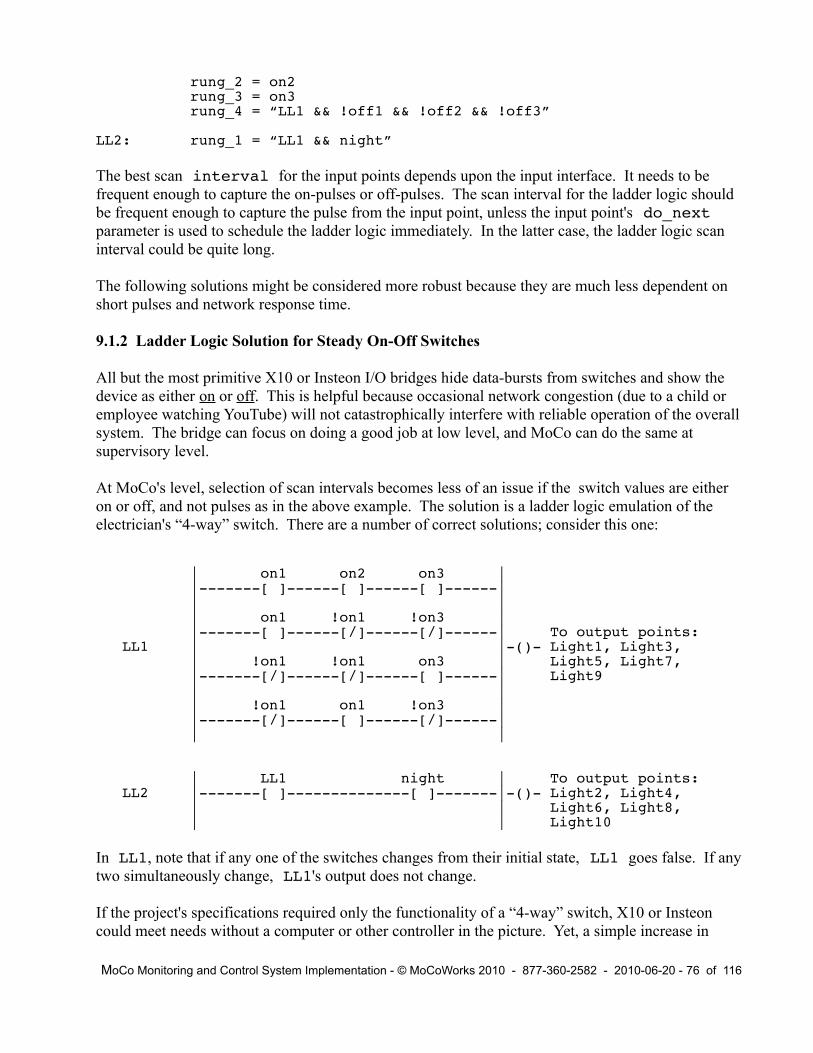
rung_2 = on2rung_3 = on3rung_4 = “LL1 && !off1 && !off2 && !off3”
LL2: rung_1 = “LL1 && night”
The best scan interval for the input points depends upon the input interface. It needs to be frequent enough to capture the on-pulses or off-pulses. The scan interval for the ladder logic should be frequent enough to capture the pulse from the input point, unless the input point's do_next parameter is used to schedule the ladder logic immediately. In the latter case, the ladder logic scan interval could be quite long.
The following solutions might be considered more robust because they are much less dependent on short pulses and network response time.
9.1.2 Ladder Logic Solution for Steady On-Off Switches
All but the most primitive X10 or Insteon I/O bridges hide data-bursts from switches and show the device as either on or off. This is helpful because occasional network congestion (due to a child or employee watching YouTube) will not catastrophically interfere with reliable operation of the overall system. The bridge can focus on doing a good job at low level, and MoCo can do the same at supervisory level.
At MoCo's level, selection of scan intervals becomes less of an issue if the switch values are either on or off, and not pulses as in the above example. The solution is a ladder logic emulation of the electrician's “4-way” switch. There are a number of correct solutions; consider this one:
| on1 on2 on3 | |-------[ ]------[ ]------[ ]------|| || on1 !on1 !on3 | |-------[ ]------[/]------[/]------| To output points:
LL1 | |-()- Light1, Light3,| !on1 !on1 on3 | Light5, Light7,|-------[/]------[/]------[ ]------| Light9| || !on1 on1 !on3 | |-------[/]------[ ]------[/]------|| |
| LL1 night | To output points: LL2 |-------[ ]--------------[ ]-------|-()- Light2, Light4,
| | Light6, Light8, | | Light10
In LL1, note that if any one of the switches changes from their initial state, LL1 goes false. If any two simultaneously change, LL1's output does not change.
If the project's specifications required only the functionality of a “4-way” switch, X10 or Insteon could meet needs without a computer or other controller in the picture. Yet, a simple increase in
MoCo Monitoring and Control System Implementation - © MoCoWorks 2010 - 877-360-2582 - 2010-06-20 - 76 of 116

complexity, such as the night control, requires intelligence that exceeds the basic capability of X10 or Insteon. Add a control system to the picture, and tasks like motion detector control or behaviors that differ on weekdays and weekends can be easily implemented.
9.1.3 Perl Solution for Steady On-Off Switches
Some system implementers, especially the younger folks, prefer writing software code to setting up ladder logic points. In some cases, writing perl code is just simpler. Therefore, MoCo provides the hooks for creating a solution-snippet in perl code.
This is accomplished by creating a calculation-style driver subroutine. The subroutine is written in pure perl syntax at this time. (Expect MoCo to provide a less-geek means for writing program code in the future.) Perl programmers will have no problem understanding the following subroutine. If you are not a programmer, please have a look anyway. You might be able to see what is being done. Hint: The logic is the same as the preceding ladder logic.
sub calc__my_4way_switch { # Custom perl snippet to implement a # custom 4-way switch.
# Get setup before the actual work. my ($p, $pSource) = @_; # Get subr parms. $cfg{$p}{digital} = 1; # Digital point. if (&calc_BEGIN($p, $pSource, 1)) { return ""; } # Do housekeeping.
my ($LitesD, $LitesN); # Must declare custom variables.
# This is the actual 4-way switch logic. # The “w” specifies that the working-value variant is to be used.
if ( ( $cfg{on1}{w} && $cfg{on2}{w} && $cfg{on3}{w}) || ( $cfg{on1}{w} && ! $cfg{on2}{w} && ! $cfg{on3}{w}) || (! $cfg{on1}{w} && ! $cfg{on2}{w} && $cfg{on3}{w}) || (! $cfg{on1}{w} && $cfg{on2}{w} && ! $cfg{on3}{w}) ) { $LitesD = 1; } # The 4-way switches say ON. else { $LitesD = 0; } # The 4-way switches say OFF. # The following deals with the “night” situation (activates more lights). # If night, turn on more lights. “night” is a time clock result.
$LitesN = ( $LitesD && $cfg{night}{w} );
# Note that we are creating 2 outputs. Unusual concept, but legal.
&calc_END("LitesN", $LitesN); # LitesN is a secondary output return &calc_END("LitesD", $LitesD); # LitesD is the primary point. } #END calc__my_4way_switch
To assure proper operation, LitesD.cfg and LitesN.cfg need to be setup with p, driver, and interval parameters. The driver in this case is the name of the subroutine: calc__my_4way_switch. The “calc” in the subroutine name is required. For custom subroutines, two underscores follow the calc to prevent name conflicts.
MoCo Monitoring and Control System Implementation - © MoCoWorks 2010 - 877-360-2582 - 2010-06-20 - 77 of 116

The second .cfg file (LitesN.cfg) is almost a dummy, because the system expects only one result variable from a point. Two outputs – sneaky, but functional. LitesD is the primary output. Its .cfg file should contain the do_next parameter that lists all 10 output points for the lights.
This custom driver is not a general purpose driver because it is hard-coded for the variables shown. With a little extra work, the 4-way portion of the code could be made into a general-purpose 4-way switch driver – and maybe it will become a standard driver some day. Heck, why not a n-way switch driver.
9.1.4 Too-easy MoCo Solution for Steady On-Off Switches
MoCo allows multiple sources to be sent to one or more outputs – many to many. Each input point for each of the switches can be fed to a single or multiple output points via the input point's do_next parameter. Whenever one of the switches is turned on, the target output point will go true. Whenever one of the switches goes off, the output will go off. This works as desired because a signal is propagated to the output point via the do_next parameter only when a change in input occurs. Even though the switch inputs are being scanned on a 10-second interval, changes are propagated by do_next only when a change in the point's value occurs.
9.2 Duty Cycle Calculation
“Duty cycle” is the percentage of time that a device, heating element, or machine is running. Monitoring the duty cycle of a refrigeration system is, for example, a good way to keep an eye on the health of the system. Duty cycle is a measurement that must be read over time. It involves careful timings and simple calculations. The following example shows how this might be done with MoCo.
We will monitor the on-off states of a motor, and calculate the duty cycle over a period of 30 minutes, which repeats forever. We want to display the result as a point. This can be achieved with a calc_expression point that calculates the result every scan interval of 30 minutes with the help of the point's stopwatch timer.
The MotorDCx point uses the calc_expression driver to evaluate the following expression:
expression = “MotorDCx.timer * 100 / MotorDCx.time_intv”
The expression does the duty-cycle calculation. Timer MotorDCc.timer runs when the motor is running, and stops when the motor stops. It resets from internal variable MororDCx.doing_pt just after processing the point. Variable MotorDCx.time_intv is an accurate measure of the interval over which the calculation is being performed. The doing_pt variable is true only when the point is being processed, and that is when we want the counter reset. The counter's parameters are setup in MotorDCx.cfg. Relevant parameters look like this:
intv_only = 1 # Allow calcs only at interval-time. interval = 1800 # 30-minute interval.
start = Motor # Motor-on. Starts with timer running.stop = !Motor # Motor-off. Stops the timer.reset = MotorDCx.doing_pt # Reset the timer every 30 minutes.
MoCo Monitoring and Control System Implementation - © MoCoWorks 2010 - 877-360-2582 - 2010-06-20 - 78 of 116

At the end of the cycle, the timer might just keep on running. But, it is reset at 30 minute intervals at the end of each calculation.
To prevent such calculations from being performed at times other than the interval, set the point's intv_only to 1 as shown above.
There are other ways to calculate duty cycle, which are a better fit for long on-off cycles. See if you can design one. Hint: You may need two timers.
9.3 Door Opening Counter
If a person needs to count how often a door is opened or how many people pass a sensor, this example provides a start.
In this example, we count the number of door openings per 15-minute interval. The results indicate the busiest times of day. The counts per 15 minute window are converted to door openings per hour This can be achieved with a calc_expression point that calculates the result every scan interval of 15 minutes, and with the point's up/down counter.
DoorCntX is the point's ID. The calc_expression driver evaluates the following expression for point DoorCntX:
expression = “DoorCntX.counter * 3600 / DoorCntX.time_intv”
The expression does the “door-openings per hour” calculation. Counter DoorCntX.counter increments when the door opens. It does not double-count because the counter increments only on the leading edge of the door-open pulse. The counter resets from internal variable DoorCntX.doing_pt just after processing the point. The counter's parameters are in file DoorCntX.cfg. Relevant parameters look like this:
intv_only = 1 # Allow calcs, only at interval-time. interval = 900 # 15-minute interval.
counting = 1 # Enables the counter to count.count_up = DoorOpen # DoorOpen point increments the counter.reset = DoorCntX.doing_pt # Reset the counter every 15 minutes.
The counter is always free to keep counting, but the configuration above causes it to reset every time the calculation runs – every 15 minutes. The point's intv_only parameter is set to 1 to prevent a calculation from being performed more frequently than the 15-minute interval.
Note that there are speed limits for the I/O bridge and MoCo itself – perhaps several seconds for propagation delays between the I/O hardware, network, and computer. Counting door openings should be reliable using the above scheme, but measuring a flow meter's 3000 counts per minute would have to be done in an entirely different manner. Rapid counting would need to be done at the I/O bridge level.
MoCo Monitoring and Control System Implementation - © MoCoWorks 2010 - 877-360-2582 - 2010-06-20 - 79 of 116

9.4 Scenes and Sequencing
The following example turns on three ladder logic points in sequence, and turns off three ladder logic points in sequence. Each ladder logic result can be used to drive an output device. This simulates sequencing lights, motors, heating elements, etc.
When the on-signal goes true, the first ladder logic output goes true. 30 seconds after start, the second ladder logic point goes true. 90 seconds after start, the third ladder logic point goes true.
When the on-signal goes false, the third ladder logic goes false. 20 seconds after start, the second ladder logic point goes false 40 seconds after start, the first ladder logic point goes false.
The implementation is done with three ladder logic points, and with two of their timers. A diagram of the ladder logic follows:
Timer Parameters:| on |
stage1 |-------[ ]------------------------| start = on| | stop = !on| !on stage2.timer < 40 | reset = !on|-------[/]--------------[ ]-------|-( )-| |
| on stage1.timer > 30 | timer = 1000 stage2 |-------[ ]--------------[ ]-------| start = !on
| | stop = on| !on stage2.timer < 20 | reset = on|-------[/]--------------[ ]-------|-( )-| |
| on stage1.timer > 90 | stage3 |-------[ ]--------------[ ]-------|
| |-( )-| !on stage2.timer < 1 ||-------[/]--------------[ ]-------|| |
The three ladder logic points are called stage1, stage2, and stage3. Timers from stage1 and stage2 are used in this example. (Remember that all points have an available timer.) The timers' .cfg parameters are shown to the right. They are setup in stage1.cfg and stage2.cfg, along with the ladder logic rungs shown above. The rungs for stage3 are:
rung_1 = "on && stage1.timer > 90"rung_2 = "!on && stage2.timer < 1"
When point “ on ” becomes true , stage1's timer begins counting up. This behavior is enabled by the timer's start parameter, shown to the right. stage1's output becomes immediately true. Stages 2 and 3 follow in 30 and 90 seconds, respectively, until all three are on.
MoCo Monitoring and Control System Implementation - © MoCoWorks 2010 - 877-360-2582 - 2010-06-20 - 80 of 116

When point “ on ” goes false (in other words, off), timer 1 is stopped and reset. Timer 2 is started. Almost immediately, stage3 goes false. After 20 seconds, stage2 goes false. After 40 seconds, stage1 goes false. Now they are all off.
At first glance, the ladder logic implementation might look bug-free. However, when creating programs and ladder logic there is often the risk of problems at system startup. The timers trigger on the leading edge, a change from false to true. When starting up, timer 2 is at zero. Inspect the ladder logic and you can see why this creates a problem. A simple solution is to initialize timer 2 to a value higher than 40. The initialization is done in the stage2.cfg file, as shown above with timer = 1000.
A person proficient with ladder logic will find tasks like this easy, and perhaps even boring. A software programmer, on the other hand, would argue that writing program code is easier. This is a classic argument, akin to arguing politics and religion. In any case, be assured that software program style solutions will be added to MoCo so you can do it your way. Or, code it in pure perl code if you like.
MoCo Monitoring and Control System Implementation - © MoCoWorks 2010 - 877-360-2582 - 2010-06-20 - 81 of 116

10. Maintenance
10.1 Backups
Backup frequently: The database file, all configuration files, log file, and anything else that might have changed.
10.2 Log File
Archive and clear moco.log once a month, or so.
10.3 Database
The moco.db database has three tables:
history For all that historic point data.snapshot For status data for mocos, and for sharing live data between systems.message For sending messages from program mocom to other programs.
Because multiple handlers write to the snapshot database table, MoCo programs never automatically clear it. That would cause problems when more than one handler is running. At enterprise level, further care must be taken because distributed computers talk to the same database.
Therefore, sometime after deleting or renaming points, it is a good idea to run the script clear-snapshot after shutting down all handlers that might be using the database. The clear-snapshot script simply deletes all records from the snapshot table. It does not DROP and CREATE the table. The sample mocod-start script clears the snapshot table at startup.
For systems that are up 24x7 or distributed on different computers, obsolete (or re-named) point-records can be removed from the snapshot table with the sqlite3 program. Delete records with SQL's DELETE statement. In this scenario, there is no need to shut down anything.
Unless your startup script clears the message table at startup, delete all the records in the message table at least once per year. The clear-message script will do the deed. This operation can be done at low risk, even if all systems are live. The sample mocod-start script clears the message table at startup.
If the database seems to have problems, one solution is to DROP and CREATE the tables. This destroys all data in the tables, so backup the database first. File moco-schema.sql contains the appropriate SQL statements to DROP and CREATE one or all tables. sqlite3 can execute one or more SQL statements at a time. Copy and paste the desired SQL statements to sqlite3's command line, and strike [enter]. It will be done in a flash.
MoCo Monitoring and Control System Implementation - © MoCoWorks 2010 - 877-360-2582 - 2010-06-20 - 82 of 116
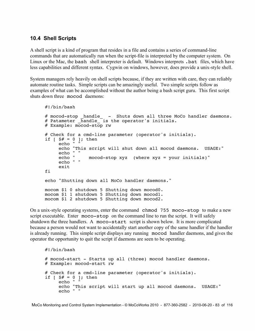
10.4 Shell Scripts
A shell script is a kind of program that resides in a file and contains a series of command-line commands that are automatically run when the script-file is interpreted by the computer system. On Linux or the Mac, the bash shell interpreter is default. Windows interprets .bat files, which have less capabilities and different syntax. Cygwin on windows, however, does provide a unix-style shell.
System managers rely heavily on shell scripts because, if they are written with care, they can reliably automate routine tasks. Simple scripts can be amazingly useful. Two simple scripts follow as examples of what can be accomplished without the author being a bash script guru. This first script shuts down three mocod daemons:
#!/bin/bash
# mocod-stop _handle_ - Shuts down all three MoCo handler daemons.# Patameter _handle_ is the operator's initials.# Example: mocod-stop rw
# Check for a cmd-line parameter (operator's initials).if [ $# = 0 ]; then echo " " echo "This script will shut down all mocod daemons. USAGE:" echo " " echo " mocod-stop xyz (where xyz = your initials)" echo " " exitfi
echo "Shutting down all MoCo handler daemons."
mocom $1 0 shutdown 5 Shutting down mocod0.mocom $1 1 shutdown 5 Shutting down mocod1.mocom $1 2 shutdown 5 Shutting down mocod2.
On a unix-style operating systems, enter the command chmod 755 moco-stop to make a new script executable. Enter moco-stop on the command line to run the script. It will safely shutdown the three handlers. A moco-start script is shown below. It is more complicated because a person would not want to accidentally start another copy of the same handler if the handler is already running. This simple script displays any running mocod handler daemons, and gives the operator the opportunity to quit the script if daemons are seen to be operating.
#!/bin/bash
# mocod-start - Starts up all (three) mocod handler daemons.# Example: mocod-start rw
# Check for a cmd-line parameter (operator's initials).if [ $# = 0 ]; then echo " " echo "This script will start up all mocod daemons. USAGE:" echo " "
MoCo Monitoring and Control System Implementation - © MoCoWorks 2010 - 877-360-2582 - 2010-06-20 - 83 of 116

echo " mocod-start xyz (where xyz = your initials)" echo " " exitfi
# Display mocod handler daemaons that are currently running here.echo " "echo "Please be certain that no 'mocod' daemons running!"echo "In other words, NO 'mocod 0', 'mocod 1', etc. (see below)"ps -Af | grep mocod # Display any mocod daemons.
echo " "echo -n "Would you like to continue the startup? [y/n]: "read answerif [ "$answer" == "y" ]; thenecho "Preceding to startup MoCo ..."else echo "Aborting MoCo startup." exit 0fi
# Clear the snapshot and message tables in the database.echo "Clearing 'snapshot' db table with script 'clear-snapshot'."clear-snapshot # Script.echo "Clearing the 'message' db table with script 'clear-message'."clear-message # Script.
# Startup the mocod daemons, all in same terminal window.mocod 2 &sleep 10mocod 1 &sleep 10mocod 0 &
This script starts all daemons in the same terminal window. The trick is the “&” at the end of the line, which causes the daemons to be run in the background. When programs are running in the background, they cannot be aborted with a [control+c]. If they must be rudely killed, they can be killed with the system's kill command (on non-windows systems). However, it is nicer, safer, more platform-consistent, and more convenient to use the mocom shutdown commands – or better yet, a script like the mocod-stop script.
The above scripts will not produce the desired results if any of the three handlers are already running for mocod-start. In such cases, the operator will need to clean up by individually starting or stopping handlers with the appropriate commands. Scripts that are capable of handling all unusual situations become somewhat more complex.
MoCo Monitoring and Control System Implementation - © MoCoWorks 2010 - 877-360-2582 - 2010-06-20 - 84 of 116

11. [ ] Basic Transducer Electronics
11. [ ] Example Projects
12. [ ] Creating a Web-based User Interface
13. [ ] Configuring an Enterprise-level Distributed Network
By “Enterprise-level” we mean instances of MoCo that are running on multiple computers, either on the same local area network or distributed world-wide. The most significant physical difference between a one-computer configuration and a multi-computer configuration is that a centralized server-style database is used. Although the server-style database is the best way to go, there are other ways to link distributed MoCo systems if a server-style database is out of the question.
SQLite is not a server-style database, which is one reason why it is relatively easy to setup and maintain. Databases such as Oracle, mysql, PostgreSQL, and Informix have the required capability. Their architectures have a central server that is accessed by distributed clients via the network.
MoCo is tested only on SQLite at this time. However, the larger databases should be useable without changing a line of MoCo code because the SQLite implementation uses the same standard DBI interface that the big boys use. However, it will be necessary to correctly setup the following three .ini parameters:
dbi_auth Authentication (password), as needed by the db software and the DBI standard.dbi_driver Driver-name string that is compliant with the DBI standard. “DBI:....”
The dbi_driver string will have multiple sub-parameters.dbi_user User-name, as needed by the db software and the DBI standard.
These parameters include the driver name, database user name, database password, database name, server URL, and port number. Unless a person knows precisely all the parameters, setup can be difficult. That is why corporate environments have database managers. If you want to do this on your own, read up on the perl DBI database interface module, sift through the database documentation, and make friends with your company's database manager.
14. [ ] Writing a Custom Perl Snippet
15. [ ] Writing a Driver
MoCo Monitoring and Control System Implementation - © MoCoWorks 2010 - 877-360-2582 - 2010-06-20 - 85 of 116

Appendix A - Parameters
A.1 Parameters in moco.ini FIle
The primary file for MoCo's operating parameters is moco.ini. As a MoCo installation evolves, the system builder may find reasons to put some of the system parameters in handler-specific files, like mocod0.ini or mocod2.ini. The number just prior to the dot is the daemon number. Parameters in these latter two .ini files will override parameters (of same name) that are in moco.ini or hard-coded in the program.
When the system starts up, it searches for relevant .ini files. MoCo programs search in the following places, and in the following order for the .ini files:
/etc, /etc/moco.d, /home/moco, /home/$user, /home/$user/moco, ./
If moco.ini is in another directory, the path and name can be entered with MoCo program commands, like this:
mocod 2 mocod-dvrs ini_file=/User/reed/bin/moco.ini
Once a mocod daemon has found the moco.ini file, it looks for a .ini file for it's instance, or handler. For the example above, it would look for mocod2.ini. This .ini file is optional.
Next, MoCo a program needs to know where to find the various other configuration files (.cfg, .rpt, .usr, and .lcl files). Unless, it finds a cfg_dir parameter in a .ini file, it assumes the other configuration files are in the program's run directory.
If all MoCo files are in the same directory, a user needs to worry about none of the above. However, the options described above provide the flexibility needed to setup a secure environment, if needed.
In a small system, all the needed driver subroutines will be in perl files mocod, mocod-seg1.pl, mocod-seg2.pl, and mocod-dvrs.pl, the defaults. However, drivers may also have other file-names. A mocod handler can load additional driver files. One driver file can be specified in .ini parameter dvrs_file. If there is more than one driver file, the additionals can be specified in array parameters, starting with dvrs_file[0] or dvrs_file[1]. These can be isolated to a specific handler by placing the parameters in the appropriate mocod?.ini file. Again, this potential flexibility can be ignored for most small or medium systems.
System managers can add their own parameters. Both the documented parameters and a user's parameters can be read by MoCo's point-processing software wherever a point-id or expression is allowed. When point software references ini parameters, pre-defined or user-defined parameter names looks like the following: ini.rpt_span or ini.my_parm.
A parameter in a .cfg file can “indirect” to a parameter in the .ini file. To setup an indirect in
MoCo Monitoring and Control System Implementation - © MoCoWorks 2010 - 877-360-2582 - 2010-06-20 - 86 of 116

a .cfg file, precede the target's name with “->ini.”. For example: net_addr = ->ini.net_addr_ha7net. This saves entering a specific network address in perhaps two dozen .cfg files, which facilitates future changes. Just change the network address in one place, the .ini file.
Other .ini parameters that may be of interest are listed below. Except for the net_addr parameters, few of these need be setup or adjusted for a single-handler, beginners system:
calc_loops Number of times to loop the calculation points before quitting. Default: 5.cfg_dir Directory for configuration files (other than the .ini files). Default: pgm run dir.db Database file location. Default: $ini{pgmDir}/$ini{pgmFamily}.dbdb_run Database utility program. Default: $ini{pgmDir}/sqlite3.exedbi_auth Authentication (password), as needed by the db software and the DBI standard.dbi_driver Driver-name string that is compliant with the DBI standard. DBI:....dbi_user User-name, as needed by the db software and the DBI standard.db_software Database software name. Default: SQLitedtFmt Default: $y2$mo$md-$hr$mi$se$gmtdvrs_file File name of driver file. Default: mocod-dvrs.pldvs_file[?] File names of driver files, if more than one.hist_interval Longest time allowed between history writes. Default: 2000 seconds.logFile Log file, including optional path, for errors and more. Default: Program's directory.msg_interval Interval for polling for messages from mocom. Default 13 seconds.no_output Blocks all outputs when =1. Useful for enabling/disabling redundant systems.net_addr_ha7net Example of indirect addr for input_webcontrol, http://192.168.0.250net_addr_wc0 Example of indirect addr for input_webcontrol, http://192.168.0.240net_addr_wx Example for input_web_page, http://bistrobrew.com/weather/clean-wx.htmnet_timeout Default: 10 seconds.node Usually the computer's name or a user's account name. All node_names in a MoCo
network must be unique. A required parameter if more than one computer.rpt_dir Directory for .rpt report files. Default is the .ini's directory.rpt_span Default span for mocor report. Default: 4h (4 hours).time_now Current system-time in seconds. Useful for calc points. Read-only.usr_dir Directory for .usr user-definition files. Default found from search sequence.
A.2 Point Parameters in .cfg Files
Most of the following parameters have reasonable system defaults, and are therefore not required.Required parameters are in bold. Parameters that may be required, depending upon the driver, are identified with an asterisk “*”. Underlined parameters can accept parameter-ids or expressions, as well as a number.
Keep in mind that users can add their own parameters to .cfg files. Both the documented parameters and a user's parameters can be read by MoCo's point-processing software wherever a point-id or expression is allowed. A custom parameter might look like OAT.season when used as a point's parameter value.
MoCo Monitoring and Control System Implementation - © MoCoWorks 2010 - 877-360-2582 - 2010-06-20 - 87 of 116

As mentioned above, a parameter in a .cfg file can “indirect” to a parameter in a .ini file. To setup an indirect in a .cfg file, precede the target's name with “->ini”. For example: net_addr = ->ini.net_addr_ha7net. This saves entering a specific network address in perhaps two dozen .cfg files, which facilitates future changes.
A.2.1 All Points
Most of the following have system defaults, and are not required. Required parameters are in bold. Most of the parameters might be included in the .cfg file, but some are run-time variables that are useful for reading at run-time, only. Underlined parameters are numeric variables that can accept variable-names or expressions, as well as numbers.
alarms Enables alarms. A prioritized list of alarm characters, staring with “!”.alarm_? Alarm definition. ? is alarm ID. Contains threshold, direction, remark, etc.alarm_to_? Alarm threshold override level. ? is alarm ID. Can be manipulated via mocom.cmd_a_? If ? is A-Z: Alarm A-Z is active and latched. Execute shell cmd in this parameter.
If ? is a-z: Alarm a-z acknowledged. Execute shell cmd in this parameter.cmd_a_ac When all alarms are cleared, execute the the shell cmd in this parameter.cmd_a_bd When a bad data “?” alarm occurs, execute the the shell cmd in this parameter. cmd_a_ma When a manual alarm occurs, execute the the shell cmd in this parameter.cmd_a_mc When a manual alarm is acknowledged, execute the the shell cmd in this parameter.cmd_c_0 If clean value goes false, execute the the shell cmd in this parameter.cmd_c_1 If clean value goes true, execute the the shell cmd in this parameter.cmd_o_0 If a user turns off an override, execute the the shell cmd in this parameter.cmd_o_1 If a user turns on an override, execute the the shell cmd in this parameter.cng_filter Allows only specified logic transition to do_next a point. Set =1 for false-->true, set
=-1 for true-->false. Used with calc points where interval = 0.count_down Leading edge of the variable's pulse causes counter it decrement.count_up Leading edge of the variable's pulse causes counter it increment.counting Counting enabled. Use in .cfg to enable counting by setting equal to 1.desc Point description, up to 40 characters.digital =0 for analog point, =1 for digital. Default, 0 or 1, is set by individual driver.disable =1 to disable the functionality of a point, almost as though it does not exist.do_next * List of point or points to process immediately next.doing_pt Used to reset timer/counter so that the reset occurs after the point is run.driver Name of the subroutine that does the work for for this kind type of point.enable_out Enables do_next triggering of output points. If not utilized, default is “enabled.”force If true, force result or output to become the value from val_force.gate Gates the point's result. See details at analog and digital points. Default is null.handler Instance of mocod daemon, to use for this point. mocod0 is default.interval Scan interval seconds. Default: 60 seconds. If 0, then normal scanning is disabled.intv_only If =1, the scheduler will run the point's driver only on the interval.logic_cng Reports a logic change. 1 for false-->true, -1 for true-->false. See cng_filter.name Point name, up to 20 characters. Recommended.p Point -d, like IAT or Heat3+. Must match .cfg file. 8 or less characters.point_type input, output, calc, or time. Set by mocod.reset Resets timer/counter to 0 on the leading edge of a value going from false to to true.
MoCo Monitoring and Control System Implementation - © MoCoWorks 2010 - 877-360-2582 - 2010-06-20 - 88 of 116

start Starts the timer upon the leading edge of a value going from false to to true.stop Stops the timer upon the leading edge of a value going from false to to true.snap_fmt Specifies sorting order and header text to be used in mocos status reports.stealth =1 to prevent the point from being normally displayed in reports.time_prev System-time in seconds of previous pass. Useful for calc points. Read-only.timer The current time accumulated on a timer. Typically, read-only; but may have
a value in .cfg in order to assure clean ladder logic startup in some situations.units Physical units, like degF or volts. 5 or less characters. Recommended.val_force If force is true, then force the point's result or output to assume this value.val_over Override value. Normally set via mocom. Default is null.
A.2.2 All Analog Points
Analog points produce numeric results that have receive extensive processing, which is controlled by the following parameters. After processing, the results usually look different (cleaner) than the original raw values.
avg_size Number of readings to average in the running average. 1 to any size. Default: 1.bad_high Block data, replacing with “?”, if above this value. Helps detect bad sensors.bad_low Block data, replacing with “?”, if below this value. Helps detect bad sensors.gate Typically =0 or =1. gate is multiplied times a point's value to create the result.high_limit Clamps the converted value to stay at or below the high_limit.hysteresis Hysteresis applied to the history value and clean value. Default 1/8 of resolution.low_limit Clamps the converted value to stay at or above the low_limit.offset For converting to different units (like degC to degF), or sensor calibration.ramp Maximum allowed rate-of-change per minute of the clean value. Default: no limit.resolution Resolution of history or clean value, like 1, .1, .02, etc. Default: 1.scale For converting to different units (like degC to degF), or sensor calibration.
A2.3 All Digital Points
Digital points can be any kind of number, and even short strings of text. They are not altered in any way by MoCo, unless they are overridden, gated, inverted, or have bad data.
bad_high Block data, replacing with “?”, if above this value. Helps detect bad sensors.bad_low Block data, replacing with “?”, if below this value. Helps detect bad sensors.gate Typically =0 or =1. The gate value is multiplied by the intermediate value
and converted to an integer to create the final result.invert =”.” causes an I/O point's value to be inverted, compensating for I/O inversion.
A.2.4 Specific to Input Points
channel * Channel number, 1 or 0, for HA7Net digital input or output drivers.device Manufacturer's part ID. Usually for information only; and not required.
MoCo Monitoring and Control System Implementation - © MoCoWorks 2010 - 877-360-2582 - 2010-06-20 - 89 of 116

device_id ID of the input sensor, or port like, t2 or F20000013E41C828. Depends upon bridge.in_file * Name of input file for driver input_file.in_or_out * input_ha7net_digital: =input if an input-only point, and =output
if output point. Both input and output points can be read by the driver.invert If =”.”, it inverts digital inputs to compensate for I/O inversion. Displays with “.”.net_addr * Network address for bridge or web page. Can point to web addr in moco.ini.scope input_alarm: =0 to cover handler, =1 to cover MoCo node, =2 to cover all points.
A.2.5 Specific to Output Points
channel * Channel number, 1 or 0, for HA7Net digital input or output drivers.cmd_outf * Shell command to execute whenever a file from output_file is written.device Manufacturer's part ID. Usually for information only, and typically not required.device_id ID of the output actuator or port like, o3. ID depends upon the bridge.force If true, force the output to become the value from val_force.gate Typically =0 or =1. The gate value is multiplied by the intermediate value
and if digital is converted to an integer that is sent to the output device.invert If =”.”, causes an output point's value to be inverted, to compensate for I/O inversion.net_addr * Network address for bridge or web page. Can point to web addr in moco.ini.no_output Blocks output when =1. If =-1, enables output even if ini.no_outputs=1.
Useful for enabling/disabling outputs in fail-safe, redundant systems.out_file * Name of output file for driver output_file.pulse_sec Number of seconds of optional output pulse. Default is null.pulse_trig Generate optional pulse on trigger: up, down, both. Default is null.source_pt * Optional source-point that can be specified to be used by an output point.variables * Source variables for output_file driver. = PointA|PointB.c|PointCval_force If force is true, then force the output to assume this value.
A.2.6 Specific to Calc Points
expression * calc_expression driver: Math/logic expression to be evaluated.function * calc_functions driver: sum, avg, min, max, abs, or int.parameters * calc_functions driver: Parameters for the math function.rung_ ? * calc_ladder_logic driver: Ladder logic expressions. Rungs 1-100.time_intv An accurate measure of the last interval, in seconds.time_now System time in seconds, now.time_prev System in seconds at the previous interval.
A.2.7 Specific to Time Points
pulse_sz * time_clock: Pulse length in seconds when p or d in times parameter.times * time_clock: List of time-events, such as times of day, dates day of week, etc.
MoCo Monitoring and Control System Implementation - © MoCoWorks 2010 - 877-360-2582 - 2010-06-20 - 90 of 116

A.2.8 Useful Internal Real-time Data Variables
alarm The single-character alarm status: _, a-z, A-Z, ?, !c Clean value – a point's smooth, conditioned result value, with override capability.w Working value – a point's higher resolution value, with override capability.v Same as point.w, except without ability to be overridden.h Same as point.c, except without ability to be overridden.val_raw A point's raw value, as it leaves the driver, but before being scaled and conditioned.
Various other real-time control variables are described throughout this document.
A.3 Report Parameters in.rpt Files
The following are conventional parameter-file parameters:
line[?] Lines of text that are used for report headers and footers.p_mask Specifies the scope of point-ids for the report.rpt_name Multi-word name for the report.rpt_span Report duration, like: 30m, 8h, 7d, 1mo.rpt_type Event-type scope of the report: E, a, A, o, u, r, c, C.
The following are used within line[?] parameters to pass program data to headers or footers:
$datetime Human-readable date and time.$p_mask Scope of point-ids for the report actually used. (p_mask may have been overridden)$rpt_file Actual name of this file.$rpt_type Actual event-type scope of the report. (rpt_type may have been overridden)
A.4 User-identification Parameters in.usr Files
A .usr file is needed for each user who will use mocom. The .usr files are merely the first step toward a real security system. A user's handle should probably be short, as two or three initials. When users execute mocom commands (as when acknowledging an alarm or setting an override), they must enter their handle – typically their initials. Each command and the user's hanndle are recorded in the moco.log file. At this stage of development, the option for passwords has not been implemented.
The system manager's .usr file, moco-sm.usr, must be on the system. All the other users' .usr files must be in the same directory. When looking for a .usr file, programs search a half dozen likely directories, starting with the directory specified in the optional usr_dir parameter in a .ini file. When the system manager's file is found, searching stops at that directory. Because the usr_dir parameter is security-related and for more reasons, .ini files should be protected in a secure environment.
This scheme prevents a bogus user from simply inserting a .usr file at an accessible directory in
MoCo Monitoring and Control System Implementation - © MoCoWorks 2010 - 877-360-2582 - 2010-06-20 - 91 of 116

the search path. Better security (passwords) will be added in the future, as needed.
The .usr file must be named, beginning with “moco-” followowed by the user's handle followed by .usr, like: moco-rw.usr. Inside the file, only the user's full name is required at this time:
my_name = “Reed White”
MoCo Monitoring and Control System Implementation - © MoCoWorks 2010 - 877-360-2582 - 2010-06-20 - 92 of 116

Appendix B - Sample .cfg Files
These sample files are are included here as a reference for parameters that can be used with specific point types. They are not intended to be practical files. The files contained with the software will be the most recent versions.
B.1 Input .cfg File Sample
# sampleIn.cfg - Sample Input Point
# Basic point definition.p = sampleIn # Point-ID, for software and reports.name = "Sample Input" # Point-name, for reports. desc = "Sample Input Point" # Long point description.units = degF # Units, for report display.device_id = F20000013E41C828 # Manufacturer's unique sensor ID.net_addr = ->ini.net_addr_ha7net# To sensor's web addr in moco.ini.device = DS18B20 # Mfgr's sensor part ID, for info.driver = input_ha7net_temp # Handler subroutine name.handler = mocod9 # Daemon 9, the handler for this point.
# For analog processing. (all optional, some more important than others)# Choose the following numbers wisely:avg_size = 5 # Number of samples for running average.resolution = 0.2 # "Clean" resolution, for risplay and history.ramp = 0.5 # Allowed rate of change per minute.hysteresis = 0.03 # To reduce history jitter & inc data instability.interval = 10 # Sampling cycle interval in seconds.high_limit = 100 # The value is clamped at or below this limit. low_limit = 30 # The value is clamped at or above this limit.bad_high = 110 # If raw conv val at or above, flagged as bad data.bad_low = 20 # If raw conv val at or above, flagged as bad data.invert = . # If =".", raw input is inverted, and "." displ.
do_next = point1|point2|point3 # for rapid processing of result.
# snap_fmt defines the display format for mocos.pl report.# This is optional, but recommended for a finished system. # "|" (pipe) is the field-delimiter. 1st & 2nd fields for sorting lines.# 3rd field is text for a prior break-line between rows (if any).snap_fmt = "2|a|Inside ........................................."
# Alarms are optional, usually for critical points only:alarms = !|H|C|w|c # ="" (null) for no alarms configured. # =! to allow just ! and ? alarms. # =!|H|C|w|c... (example) Mult alarms. # Upper-case latched, lower unlatched. # Multiple alarms defined below. One example shown: alarm_H = "72.5|U|.2||c|Getting warm in here!" # Parameters for alarm: # 1st - Alarm threshold value, required. # 2nd - Direction, U up or D down. # 3rd - Hysteresis. # 3rd - 1-char ID for display.
MoCo Monitoring and Control System Implementation - © MoCoWorks 2010 - 877-360-2582 - 2010-06-20 - 93 of 116

# 4th - Rate of change/min threshold. # 5th - Point's value variant, like: c, w, v, h, etc. # 6th - Very short alarm description.alarm_C etc. (additional alarms not shown here)
# Triggering of shell scripts or programs from alarm events.cmd_a_H=my-script1 # Alarm “H”, for ex, has been triggered & latched. # (Use any alarm id, A-Z.) # If a no-latch alarm, do not use cmd_a_H. Instead # use cmd_a_h to trigger a shell command when the # alarm has gone active and auto-acknowledged.cmd_a_h=my-script2 # Alarm “H” has been acked, now displayed as “h”.cmd_a_bd=my-script3 # A “?” bad-data alarm triggered. It does not latch.cmd_a_ma=my-script4 # The “!” manual alarm has been triggered & latched.cmd_a_mc=my-script5 # The “!” manual alarm has been cleared.cmd_a_ac=mt-script6 # All alarms are now clear.
# Various Overrides (all are optional):force = "1" # If true, val_force value is used as override.val_force = "70" # The value to assuem if parameter force is ture.gate = 1 # For gateing the result value.val_over = "" # Manual override. Usually altered via mocom.alarm_to_H = 75 # Alarm threshold override, alarm "H". mocom use.
# MoCo processing control. All are optional, & assume reasonable defaults.do_next = point1|point2|point3 # For rapid processing of result.cng_filter = 1 # If =1, do_next on leading edge only, =-1 trailing only.enable_out = 1 # If =1, do_next to output points, =0 block trig of outs.interval = 0 # If =0, no interval processing.intv_only = 1 # If =1, process only on the interval.disable = 1 # If =1, then totally disable the point.stealth = 1 # If =1, don't show by default on reports.
# ADDITIONAL USEFUL PARAMETERS:# See MoCo doc (especially Appendix A) for complete list of parms.
# NOTES:# Everything is case-sensitive.# Quote any data that contains spaces.# Order of name=value variables is not important.
B.2 Time Clock .cfg File Sample
# sampleTime.cfg - Sample Calc Time Clock Point
# Basic point definition.p = sampleTime # Point-ID, for software and reports.name = "Sample Time Clock" # Point-name, for reports. desc = "Sample Calc Time Clock Point" # Long point description.units = onOff # Units, for report display.driver = time_clock # Handler subroutine name.handler = mocod9 # Daemon 9, the handler for this point.interval = 60 # Normal interval between evaluations. # If =0, then no interval processing.
MoCo Monitoring and Control System Implementation - © MoCoWorks 2010 - 877-360-2582 - 2010-06-20 - 94 of 116

# By default, Time Clocks are digital, but they can be analog if:digital = 0 # To force point to be analog. See parms in sampleIn.cfg.
# Specific to Time Clocks. “times” is a required parameter.times = 0@wd0530|0@ss0600|1@wd1900|1@ss2000 # Event-times list.pulse_sz = Length of pulse in seconds, if pulses specified in event list.
# MoCo processing control. All are optional, & assume reasonable defaults.do_next = point1|point2|point3 # For rapid processing of result.cng_filter = 1 # If =1, do_next on leading edge only, =-1 trailing only.enable_out = 1 # If =1, do_next to output points, =0 block trig of outs.interval = 0 # If =0, no interval processing.intv_only = 1 # If =1, process only on the interval.disable = 1 # If =1, then totally disable the point.stealth = 1 # If =1, don't show by default on reports.
# Timers. Aavailable with any kind of point. (all are optional)timer = 1000 # Timer value, usualy read-only. start = pointX # Trigger's timer-start on leading edge of true.stop = !pointX # Trigger's timer-stop on leading edge of true.reset = pointY.coing_pt # Reset counter on leading edge of true.# These read-only parameters are specific to calc points. (not for .cfg)time_intv # Precise time in sec for previous interval.time_now # Precise time in sec when the calc is performed.time_prev # Precise time is nsec when the previous calc was performed.
# Counters. Available with any kind of point. (all are optional)counter # Current count on counter. Usually read-only.counting = pointI # Enables counting. Most often run-time controlled.count_up = pointJ # Count up on leading edge. Run-time controlled.count_down = pointK # Count down on leading edge. Run-time controlled.reset = pointL # Reset on leading edge. Run-time controlled.
# ADDITIONAL USEFUL PARAMETERS:# See sampleIn.cfg for examples of the following other useable parameters:# alarms, shell command triggers, and overrides.# See MoCo doc (especially Appendix A) for complete list of parms.
# NOTES:# Everything is case-sensitive.# Quote any data that contains spaces.# Order of name=value variables is not important.
B.3 Calculation Expression .cfg File Sample
# sampleExpr.cfg - Sample Calc Expression Point
# Basic point definition.p = sampleExpr # Point-ID, for software and reports.name = "Sample Expression" # Point-name, for reports. desc = "Sample Calc Expression Point" # Long point description.units = degF # Units, for report display.driver = calc_expression # Handler subroutine name.handler = mocod9 # Daemon 9, the handler for this point.
MoCo Monitoring and Control System Implementation - © MoCoWorks 2010 - 877-360-2582 - 2010-06-20 - 95 of 116

# For analog processing.# All are optional, some more important than others.# Choose the following numbers wisely:avg_size = 5 # Number of samples for running average.resolution = 0.2 # "Clean" resolution, for risplay and history.ramp = 0.5 # Allowed rate of change per minute.hysteresis = 0.03 # To reduce history jitter & inc data instability.interval = 10 # Sampling cycle interval in seconds.high_limit = 100 # The value is clamped at or below this limit. low_limit = 30 # The value is clamped at or above this limit.bad_high = 110 # If raw conv val at or above, flagged as bad data.bad_low = 20 # If raw conv val at or above, flagged as bad data.
expression = (pointA + pointB)/2 + pointC.c)/30 # Math expression.
# MoCo processing control. All are optional, & assume reasonable defaults.do_next = point1|point2|point3 # For rapid processing of result.cng_filter = 1 # If =1, do_next on leading edge only, =-1 trailing only.enable_out = 1 # If =1, do_next to output points, =0 block trig of outs.interval = 0 # If =0, no interval processing.intv_only = 1 # If =1, process only on the interval.disable = 1 # If =1, then totally disable the point.stealth = 1 # If =1, don't show by default on reports.
# Timers (available with any kind of point).timer = 1000 # Timer value, usualy read-only. start = pointX # Trigger's timer-start on leading edge of true.stop = !pointX # Trigger's timer-stop on leading edge of true.reset = pointY.doing_pt # Reset counter on leading edge of true.# These read-only parameters are specific to calc points. (not for .cfg)time_intv # Precise time in sec for previous interval.time_now # Precise time in sec when the calc is performed.time_prev # Precise time is nsec when the previous calc was performed.
# Counters (available with any kind of point)counter # Current count on counter. Usually read-only.counting = pointI # Enables counting. Unuslly run-time controlled.count_up = pointJ # Count up on leading edge. Run-time controlled.count_down = pointK # Count down on leading edge. Run-time controlled.reset = pointL # Reset on leading edge. Run-time controlled.
# ADDITIONAL USEFUL PARAMETERS:# See sampleIn.cfg for examples of the following other useable parameters:# alarms, shell command triggers, and overrides.# See MoCo doc (especially Appendix A) for complete list of parms.
# NOTES:# Everything is case-sensitive.# Quote any data that contains spaces.# Order of name=value variables is not important.
B.4 Calculation Ladder Logic .cfg File Sample
MoCo Monitoring and Control System Implementation - © MoCoWorks 2010 - 877-360-2582 - 2010-06-20 - 96 of 116

# sampleLadr.cfg - Sample Calc Ladder Logic Point
# Basic point definition.p = sampleLadr # Point-ID, for software and reports.name = "Sample Lad Logic" # Point-name, for reports. desc = "Sample Calc Ladder Logic Point" # Long point description.units = onOff # Units, for report display.driver = calc_ladder_logic # Handler subroutine name.handler = mocod9 # Daemon 9, the handler for this point.interval = 30 # Normal interval between evaluations. # If =0, then no interval processing.
# By default, Ladder Logic is digital, but it can be analog if:digital = 0 # To force point to be analog. See parms in sampleIn.cfg.
# Ladder Logic rungs, encoded as follows:rung_0 = "predawnT && (temp-in. < 70)"rung_1 = "morningT && (! sun || morn-or) && (temp-in < 68)"rung_2 = "aftnoonT && (temp-in < 72)"rung_3 = "night! && " # It's ok to use another line.
"(((temp-out < 20)&&(temp-in < 65)) || (temp-in < 63))"
# MoCo processing control. All are optional, & assume reasonable defaults.do_next = point1|point2|point3 # For rapid processing of result.cng_filter = 1 # If =1, do_next on leading edge only, =-1 trailing only.enable_out = 1 # If =1, do_next to output points, =0 block trig of outs.interval = 0 # If =0, no interval processing.intv_only = 1 # If =1, process only on the interval.disable = 1 # If =1, then totally disable the point.stealth = 1 # If =1, don't show by default on reports.
# Timers. Aavailable with any kind of point. (all are optional)timer = 1000 # Timer value, usualy read-only. start = pointX # Trigger's timer-start on leading edge of true.stop = !pointX # Trigger's timer-stop on leading edge of true.reset = pointY.doing_pt # Reset counter on leading edge of true.# These read-only parameters are specific to calc points. (not for .cfg)time_intv # Precise time in sec for previous interval.time_now # Precise time in sec when the calc is performed.time_prev # Precise time is nsec when the previous calc was performed.
# Counters. Available with any kind of point. (all are optional)counter # Current count on counter. Usually read-only.counting = pointI # Enables counting. Most often run-time controlled.count_up = pointJ # Count up on leading edge. Run-time controlled.count_down = pointK # Count down on leading edge. Run-time controlled.reset = pointL # Reset on leading edge. Run-time controlled.
# ADDITIONAL USEFUL PARAMETERS:# See sampleIn.cfg for examples of the following other useable parameters:# alarms, shell command triggers, and overrides.# See MoCo doc (especially Appendix A) for complete list of parms.
# NOTES:# Everything is case-sensitive.# Quote any data that contains spaces.# Order of name=value variables is not important.
MoCo Monitoring and Control System Implementation - © MoCoWorks 2010 - 877-360-2582 - 2010-06-20 - 97 of 116

B.5 Output .cfg File Sample
# sampleOut.cfg - Sample Output Point
# Basic point definition.p = sampleOut # Point-ID, for software and reports.name = "Sample Output" # Point-name, for reports. desc = "Sample Output Point"# Long point description.units = degF # Units, for report display.device_id = TTL2 # Output port ID.channel = 1 # Some devices have a channel ID.net_addr = ->ini.net_addr_webcontrol # Actuator's web addr in moco.ini.driver = output_webcontrol # Handler subroutine name.handler = mocod9 # Daemon 9, the handler for this point.
# Output-specific parameters. (all of the following are optional)cmd_outf = my-script1 # Execute script if output file written.force = 1 # If =1, force output to be value of val_force.gate = 255 # Gates output. Multiplies by the gate value.invert = . # If =".", raw input is inverted, and "." displ.no_output = pointZ # Blocks output if =1. If =-1, overrides global blk.out_file = file1 # Name of output file for driver output_file.pulse_sec = 10 # Pulse length in seconds, if pulse_trig specified.pulse_trig = up # Pulse trigger direction: up, down, both.source_pt = pointS # Optional source point that can be specified.variables = ptA|ptB|ptC # Source variables for output_file driver, only.val_force = If parm "force" is true, then force output to this value.
# snap_fmt defines the display format for mocos.pl report.# This is optional, but recommended for a finished system. # "|" (pipe) is the field-delimiter. 1st and 2nd for sorting lines.# 3rd is text for a prior break-line between rows (if any).snap_fmt = "2|a|Inside ........................................."
# MoCo processing control (all are optional). Available for most points. interval = 0 # If =0, no interval processing.intv_only = 1 # If =1, process only on the interval.disable = 1 # If =1, then totally disable the point.stealth = 1 # If =1, don't show by default on reports.
# ADDITIONAL USEFUL PARAMETERS:# See MoCo doc (especially Appendix A) for complete list of parms.
# NOTES:# Everything is case-sensitive.# Quote any data that contains spaces.# Order of name=value variables is not important.
Appendix C - Drivers
Name Analog/Digital Type Description
calc_expression A calc Evaluates complex math and logic expressions.
MoCo Monitoring and Control System Implementation - © MoCoWorks 2010 - 877-360-2582 - 2010-06-20 - 98 of 116

calc_functions A calc Quickly performs math functions.calc_ladder_logic A calc Evaluates multiple rungs of ladder logic.input_alarm_tally D input Tallies active and unacknowledged alarms.input_emacsys A/D input Inputs analog and digital data via EMACSYS.input_file A input Inputs data in name=value format from file.input_ha7net_digital D input Digital 1-wire input via HA7Net.input_ha7net_temp A input Temperature 1-wire input via HA7Net.input_isy99i D input Input Insteon and X10 device-states via ISY-99i.input_owserver D input Various 1-wire inputs via OW-Server.input_web_page A input Inputs data in name=value format from web.input_webcontrol A/D input Inputs analog and digital data via WebControlinput_manual D input Inputs manual or programatic data.output_emacsys D output Outputs digital data via EMACSYS.output_ha7net_digital D output Digital 1-wire output via HA7Net.output_file A output Outputs data to a file in name=value format.output_isy99i D output Output to Insteon and X10 devices via ISY-99i.output_webcontrol D output Outputs digital data via WebControl.time_clock D time Creates time-clock events.
Note that the analog/digital processing indicated above is the driver's default choice. A user can override the default by setting parameter digital to 0 to force analog, or to 1 to force digital processing.
MoCo Monitoring and Control System Implementation - © MoCoWorks 2010 - 877-360-2582 - 2010-06-20 - 99 of 116

Appendix D - I/O Bridges
When dealing with I/O bridge hardware, be aware that a manufacturers' documentation might not include all the information that is needed. The documentation may not be synchronized with the firmware and it may contain errors. Besides reading the manufacturer's manual (a must!), the user is often expected to search wikis, search forums, solicit user assistance via forums, experiment, and lastly, use email support. The following short descriptions are not a substitute for the afore mentioned process; but they should help a new user avoid common pitfalls for a particular product.
If you have anything to add that will save others time and frustration, please contact MoCoWorks. We will add your insights to this document.
D.1 HA7Net
The HA7Net bridge works with up to one hundred 1-wire sensors, input devices, and output devices. According to the Embedded Data System's web site, the HA7Net operates with the following devices:
• DS18B20: 12-bit 1-Wire Digital Thermometer• DS18S20: 9-bit 1-Wire Digital Thermometer• DS1920: Temperature iButton• TAI8540D: Humidity Module• DS2406: Dual Addressable Input/Output Switch • GP1 Counter: Pulse Counter (DS2423)• T8A: 8 Channel 0-5V Analog Input• Z2Ten: 0-10V Analog Output• DS2438: Smart Battery Monitor• DSP7x4: Digital Display
At this time, MoCo's drivers support the 1-wire temperature sensors and 1-wire DS2406 digital I/O devices mentioned above. The Dallas Maxim DS18B20 temperature sensors are available from EDS as discrete devices, and from numerous components suppliers. The other EDS products are supplied as circuit boards with parts mounted.
The HA7Net is a small black box with one ethernet port and three 1-wire ports. It requires a 6-12v power supply, which is available from EDS as an extra. The HA7Net works with both “parasitic” and “powered” wiring for 1-wire devices.
Each 1-wire port can be strapped to supply +5 volts, a ground connection, or an open circuit to the power pin, pin-6 of the RJ-12 socket. Note that 1-wire devices must have their power pin connected to +5 volts or ground, but must not be left unconnected. The HA7Net manual does not include the strapping details; but, the necessary instructions are printed on the circuit board in challengingly-small print.
NA7Net is configured via an ethernet connection. It has its own web server and web page. Login
MoCo Monitoring and Control System Implementation - © MoCoWorks 2010 - 877-360-2582 - 2010-06-20 - 100 of 116

requires a user-name and password. The defaults are “admin” and “eds”, respectively.
For more information, download the manual from the Embedded Data Systems web site at: http://www.embeddeddatasystems.com.
D.2 OW-Server
The OW-Server is a new I/O bridge from Embedded Data Systems, second generation to their HA7Net. Not surprisingly, it is similar to the HA7Net. It handles a slightly different mix of sensors, supports a maximum of 24 devices, and costs a little less. According to the Embedded Data System's web site, the HA7Net operates with the following devices:
• DS18B20 - 12 Bit Temperature Sensor• DS18S20 - 9 Bit Temperature Sensor• DS2406 - Dual Addressable Switch• DS2408 - 8 Channel Addressable Switch• DS2423 - 2 Channel Counter• DS2438 - Battery Monitor with Temperature and A/D• DS2450 - Quad A/D Converter
At the time of this writing, a manual for OW-Server has not been available from EDS. The recently-created MoCo driver supports the 1-wire temperature sensors and the 1-wire DS2406 digital I/O devices mentioned above. Support for more sensors is expected with the next MoCo software release.
The OW-Server configuration screens are more user-friendly than the HA7Net screens because they require a user to do less jumping from screen to screen. The HA7Net screens offer more options, such as output capability. The OW-Server constantly polls its inputs at approximately a 2-second cycle time, which can offer a speed advantage in some cases.
Unlike the HA7Net, the OW-Server has no on-board strapping that enables the user to select +5 volts or ground-level to be supplied on pin-6 of the RJ-12 1-wire connectors.
Other than the differences described here, the OW-Server is similar to the HA7Net. When making a purchase decision, pay close attention to the devices supported by each, and keep in mind that the OW-Server apparently does not output to 1-wire devices. See the above HA7Net description for additional setup details.
For current information, check the Embedded Data Systems web site at: http://www.embeddeddatasystems.com.
D.3 WebControl
The WebControl BRE bridge is a product of CAI Networks, Inc. It is a 4x4-inch circuit board that offers a big bang for the buck. It is versatile, cost-effective choice for hobbyists, and can be a viable
MoCo Monitoring and Control System Implementation - © MoCoWorks 2010 - 877-360-2582 - 2010-06-20 - 101 of 116

cost-effective solution for commercial environments.
Besides a diversity of I/O capabilities, WebControl has a number of other features that enable it to work as an intelligent controller. If a temperature crosses a predefined threshold, WebControl can send email or turn outputs on or off. It does not, however, have features like averaging and hysteresis, which are available in MoCo.
A new “PLC” model is in development as this document is being written. The circuit board is the same as the “BRE” model, but the PLC firmware is different. The PLC model allows the user to create and install a control program, which can be useful for low-level, fast control applications. Because the commands are not compatible with the original BRE model, MoCo needs to know which bridge you are using. When using the PLC model, place model = PLC in the .cfg files for this bridge.
WebControl handles eight 1-wire temperature sensors, one Honeywell humidity sensor, eight digital inputs, three 0-10v analog inputs, and eight TTL digital outputs. The 1-wire buss will work only with powered 1-wire devices – not with parasitic 1-wire devices or witing. The DS1822 works OK with a 3.3v supply, but the DS18B20 needs more voltage than the "3.3v" supplied on the 1-wire terminal block.
When purchasing DS1822 or DS18B20 1-wire temperature sensors, take care to not purchase the parasitic “PAR” version. They will not work with WebControl. Also, terminal 3 on the WebControl's 1-wire terminal block does not provide enough voltage for the DS18B20. CAI Support recommends obtaining the required “5v” from terminal 3 of the humidity sensor block. While this pin also provides less than 5 volts and its voltage level pulses in sync the blinking LED, it has nevertheless proven adequate for DS18B20s.
The “5v” power terminals from the 1-wire temperature terminal block or the humidity-sensor terminal block produce less than 5 volts, are current-limited, and surge in voltage in sync with the unit's blinking light. Therefore, to power external interface electronics that requires over 5 ma, use the 5v from pin 13 of the 16-pin Tyco connector, or use an external regulated 5 volt supply.
In a pinch, users have been known to solder directly to the Tyco connector pins. Better yet, order the mating connector and ribbon cable in advance. The connector is a Tyco NOVO #1658622-3, which is available from Newark Electronics (number 73K6221) and other suppliers. The part number for hundred feet of 3M mating ribbon cable is #3365/16 (Newark number 03F5907). If only several wires need be connected to the connector, the cost of the ribbon cable can be avoided by soldering #28 wires directly to the mating connector.
In early firmware versions, the WebControl bridge selected a seemingly random order for 1-wire temperature sensors and assigned them to ports T1 through T8. A configuration screen for output points (obscured several links down from the home page) gave users the impression that they could re-assign sensor ROM codes to desired temperature ports. That was a flaw in the early firmware.
Firmware v02.03.06 and beyond works properly. The newer firmware enables a person to map temperature sensor ROM code to the desired port number, T1 through T8. Obsolete firmware (with the mapping flaw) cannot be upgraded unless the board is sent to the factory for a $20 upgrade.
MoCo Monitoring and Control System Implementation - © MoCoWorks 2010 - 877-360-2582 - 2010-06-20 - 102 of 116

Therefore when purchasing a new unit, be advised to verify the firmware version.
With the BRE model, if a 1-wire temperature sensor fails to operate, WebControl returns no other warning than a temperature of 0 degrees centigrade. Unfortunately, 0C is a common temperature that is well within the range of the sensors. A safer implementation would have returned an obviously-impossible value (like -99C) when the sensor is unreadable. The PLC model has improved upon this situation.
At this time, there is no perfect workaround for this problem with the BRE model. However, if the temperature being read is an inside temperature or an outside temperature on the equator, you could set the point's bad_low parameter to 33F or 1C. Or, you could setup an alarm for 0C, thereby creating a “bad point” alarm .
Older WebControl documentation erroneously states that the analog input range is 0-5v. It is actually 1-10v. Input impedance is unspecified, but leakage current has been measured at roughly 10ua. The 10 volts is spread across the A/D converter's 1024 10-bit resolution. So that all analog input drivers are consistent, MoCo's driver converts the 0-1024 to 0-100%. The user can use MoCo's scale and offset parameters to scale to something else from there.
Digital input ports are specified at 0-5 volts, TTL compatible. Low voltage is logical-0 and high voltage is logical-1. The threshold is unspecified. If 5v is applied to the input to produce a logical-1, the current draw measures 0.5 ma. Consequently, if your design uses a transistor or set of contacts to pull the input to ground, consider adding a pull-up resistor of 1K to 3.3K between 5v and the digital input.
Digital outputs are said to be TTL compliant. Consequently, the outputs will not directly power conventional mechanical relays without an additional transistor. The WebControl outputs have stronger pull-down than pull-up capability. Therefore, when driving a solid-state optical relay, attach the relay's “+” terminal to 5 volts, and feed the negative terminal from the WebControl digital output so that the stronger pull-down capability will drive the device. Use a solid-state optical relay (like Opto 22 #Z120D10) that is guaranteed to turn on with 3-4 DC volts, minimum. Hooked up in this manner, the logic will be inverted. Consequently, inversion will likely be desirable, either in WebControl or MoCo.
In order for MoCo to work with WebControl, login-security needs to be turned off in an administration screen. Otherwise, WebControl will not play with MoCo. If the added security is desired, try using a URL address like: http://admin:[email protected]
There have been reports that a 6v power supply is inadequate. Therefore, use a good 7.5-9v supply. A 12v supply will overheat the regulator device unless a heat sink is added to the regulator.
WebControl is configured via an ethernet connection. It has its own web server and web page. Login requires a user-name and password. The defaults are “admin” and “password,” respectively.
A WebControl manual can be downloaded from the CAI Networks web site: http://www.cainetworks.com. As with any evolving high-tech product, be aware that the manufacturer's manual may not match the firmware version of the hardware you are using.
MoCo Monitoring and Control System Implementation - © MoCoWorks 2010 - 877-360-2582 - 2010-06-20 - 103 of 116

D.4 ISY-99i
The ISY-99i is a server in a small black box that is designed primarily for high-end home automation. It raises the capabilities of X10 and Insteon power-line control devices to a much higher level. If your application is home automation that is limited to lighting, sprinkler control, and such, then the ISY-99i may be all you need.
If you need more, such as analog and digital history and advanced HVAC control, then you probably also need a system like MoCo. In a factory environment, X10 would not be used; but Insteon might cautiously be used in some commercial situations.
The ISY-99i can control AC devices with X10 and Insteon protocols. X10 is typically one way – you can control a device but you cannot [in most cases] determine its actual state, on or off. X10 communicates over the building's AC wiring, although wireless remote control devices for X10 are commonly available. Insteon takes the art of residential control somewhat further by providing two-way communications, and by providing “dual band” power-line communications and air-wave communications in their network. It's mesh architecture also routinely repeats signals.
Insteon is the more reliable of the two, and it effectively covers more square footage. Because X10 is much older, however, the choice of devices is larger. Some Insteon devices have X10 capability. The two can inter-operate to some degree. The ISY-99i is targeted at Insteon, but it has essential X10 capabilities. The ISY-99i definitely facilitates interoperability, and its interoperability features are improving with newer firmware.
In order to cover more than a couple thousand residential square feet with X10, extra hardware is needed to repeat signals. Both X10 and Insteon need to be configured such that they cover both legs (aka “phases”) of the 230v wiring. A shortcoming of both X10 and Insteon is that neither of the two controls fluorescent lighting very well; but Insteon is more immune to the RF noise created by such lighting.
The ISY-99i enables a user to setup control “scenes.” It also is a great aid in linking Insteon devices (that can operate even if the server is down). For more complex situations, the homeowner can create if-than-else style programs. If the program feature is used, the server must be up at all times.
A person who needs the capabilities of both ISY-99i and MoCo has choices. The most fundamental choice is where to put the control intelligence, in the ISY-99i, or MoCo, or both – depending upon a number of debatable issues. Control engineers argue such questions until it's time to quit work and go home; so clearly, the decision is yours.
MoCo's input_isy99i driver enables the user to read the state of Insteon devices or ISY-99i scenes. Although X10 states cannot typically be read, MoCo remembers the last X10 output sent and it displays this value for each X10 output point.
MoCo's output_isy99i driver can output to both Insteon and X10 devices. For Insteon, MoCo's driver understands 0 for off, 255 for full-on, and 1-254 for in-between dim levels. However,
MoCo Monitoring and Control System Implementation - © MoCoWorks 2010 - 877-360-2582 - 2010-06-20 - 104 of 116

an Insteon device can be made to respond to 0 for off and 1 for full-on if the output point's gate parameter is set to 255. For X10, MoCo's driver understands 0 (false) for off and non-zero (true) for on.
When controlling Insteon with MoCo via an ISY-99i, you use Insteon's device address – not the alias assigned in ISY-99i. The address looks like: 1A.34.B2 MoCo's driver massages the device address to look like “1A 34 B2 1” before it sent to the ISY-99i. ISY scenes are identified with a number like 40518, which can be specified as an address. When controlling a X10 device, you use the traditional X10 house-code/unit address that looks like: A7 or G12. As with other drivers, these addresses are entered into the device_id field of the point's .cfg file.
The ISY-99i's network address must be entered into the net_addr parameter of the point's .cfg file (or indirected to the address in the .ini file). The ISY-99i requires its current user-id and password for requests received from MoCo. These are entered into the URL address like the following. Replace user, password, and 192.168.0.230 with your values:
http://user:[email protected] # Or,https://user:[email protected] # for more security.
If this method of specifying user and password is determined to be insufficiently insecure, it may be altered in a future software release.
As with other points, the specific net_addr need not be stored in each point's .cfg file. It can be stored in one place (in moco.ini) by indirecting from the .cfg file, using a pointer in the .cfg file to the .ini file like: ->ini.net_addr_isy99i
The ISY-99i is “smarter” than the other bridges, and therefore more complicated. Expect to spend time reading its manual, reading its wiki and tips, searching the forum for help. In my experience, Universal Data's email support is both responsive and competent. Their web address is: http://www.universal-devices.com.
D.5 EMACSYS
The EMACSYS bridge is a product of Phaedrus Limited in England. The controller is a 4x4-inch circuit board with a number of connectors that allow it to be connected to optional connector blocks and peripheral devices, such as relays or optical isolators. This physical architecture has some practical advantages: You only pay for the terminal blocks if they are needed. There is no need to fabricate cables. And, the processor board can be easily removed without unscrewing any wires.
The board has sixteen digital inputs, sixteen digital outputs, and eight 10-bit 0-3.3v inputs. It does not support 1-wire devices. The digital outputs are inverted, meaning that a logical 0 is high (3-5) volts and logical 1 is low volts. The MoCo driver silently corrects the inversion so that a logical 0 is zero volts and logical 1 is high volts. If you want to invert the logic again, use MoCo's invert parameter to cause another inversion.
Like the other bridges, EMACSYS includes a web server. Its software architecture allows and
MoCo Monitoring and Control System Implementation - © MoCoWorks 2010 - 877-360-2582 - 2010-06-20 - 105 of 116

encourages users to create their own custom web pages. Some example web pages are included with the product. When used with MoCo, the MoCo driver uses a custom web page called emacsys-moco.htm, which produces an output that includes all digital inputs, digital outputs, and analog inputs. This web display is primarily for the driver, and it looks like this on a browser:
di=1000000000000000do=1011000000000000ai=986|72|27|25|26|37|19|60
The controller can run a growing number of applications that are available from the manufacturer. The MoCo driver requires the Phaedrus ethernet application firmware and the ethernet interface. The firmware and web pages must be loaded into the controller before anything will work. Installation requires a Windows machine with .NET Framework installed. Installation instructions follow:
1. Download from http://www.emacsys.com, “Control Manual.pdf” and “Ethernet Manual.pdf.” Read these short manuals, paying particular attention to the instructions for installing application software.
Install the EMACSYS Ethernet Server Software:
2. Download the software from the http://www.emacsys.com site to a Windows machine.3. Place the software in a directory like D:\emacsys.4. Double-click the .msi file to install. Install in D:\emacsys.5. Read the instructions from Phaedrus Ltd.6. Plug the little ethernet board into the controller card. Run a USB cable between controller board and Windows computer. Set the controller jumper for program load.7. Power up the EMACSYS controller board.8. Startup (double-click) “EMACSYSDownloader.exe” on the Windows machine.9. Click the “Load Appware” button. Locate file Ethernet Server.hex and “Open” for download. Click “Download Appware”.
Configure EMACSYS server and load web pages:
10. Remove power, remove jumper (installed earlier), and restore power with USB cable connected.11. Startup (double-click) EthernetServer.exe on the Windows machine.12. Setup the IP address that you desire for the EMACSYS bridge (like 192.168.0.220).13. Copy emacsys-moco.htm from a MoCo media or directory to sub-directory WebPages. 14. While still in program EthernetServer.exe, use the program to transfer web pages from the PC to EMCASYS. The example web pages should be found in sub-directory WebPages. If this is unsuccessful, you may need to install .NET Framework from http://www.microsoft.com.15. EMACSYS should be ready to go, and you should now be able to access web pages on EMACSYS using the IP address assigned in step 12.16. Using a browser, attempt viewing web pages on EMACSYS.Example: http//192.168.0.220/emacsys-moco.htm
Io be consistent with other drivers, MoCo's driver converts the 1024 levels of analog data to 0-100%. The user can use MoCo's scale and offset parameters to scale to something else from the 0-
MoCo Monitoring and Control System Implementation - © MoCoWorks 2010 - 877-360-2582 - 2010-06-20 - 106 of 116

100%.
Digital outputs are open collector transistors that pull-down to 0 volts when fed with a logical 1. Because MoCo rights the logic, a logical 0 from MoCo will cause a zero-volt (pulled-down) output. When driving a solid-state optical relay, attach the relay's “+” terminal to 5 volts, and feed the negative terminal from the digital output. This takes advantage of the board's strong pull-down capability. Use a solid-state optical relay (like Opto 22 #Z120D10) that is guaranteed to turn on with 3-4 DC volts, minimum. Hooked up in this manner, the logic will be inverted. Consequently, inversion will likely be desirable in MoCo.
Alternatively, instead of using a simple terminal strip output board, you can use a LED board or relay board, all of which are available from Phaedrus Limited.
Manuals, software, and product information can are available at Phaedrus web site: http://www.emacsys.com. As with any evolving high-tech product, be aware that the manufacturer's manual may not match the firmware version of the hardware you are using.
MoCo Monitoring and Control System Implementation - © MoCoWorks 2010 - 877-360-2582 - 2010-06-20 - 107 of 116

Appendix E - Troubleshooting
E.1 General
The mocom dump commands and unix-style grep are arguably the most useful general-purpose tools for troubleshooting a MoCo system. A mocom dump command looks like this:
mocom rw OutTemp dump # Dump all OutTemp data values to screen.
grep can be used to search .cfg files or the moco.log file for a specific string (like point-id) on non-Windows systems. A grep command looks like this:
grep OutTemp *.cfg # Looking for occurrences of “OutTemp”
Often, an important clue can be revealed when browsing the log file with a text editor. To see additional run-time diagnostic data, run a mocod daemon with the -d or -D switches set. When a situation seems overwhelming, please just sit back, think, and use these simple-but-powerful tools.
Individuals with perl experience can home in on the cause of an evasive problem by inserting print commands in the perl code. Of course, always save a copy of the original file before making any modifications.
Just after installation: When mocod is run, multiple database errors are displayed. Verify that the MoCo files did not get copied in as read-only files. If they are read-only, then change them all to read-write.
Error messages containing “value>”, complaining about a snapshot database problem. Subroutine value's job is to look up the value of a point's alphanumeric parameter. If unable to find the point in memory, it looks in the database. If it cannot find the variable in the database, it issues a warning and returns “?” as the value. In other words, subroutine value could not evaluate an expression, ladder logic, or parameter name because one of the elements was nowhere to be found. Possible causes and fixes:
1. A point-name and its attribute contain a typo, probably in an expression, ladder logic,or any parameter that contains a name instead of a number. Verify accurate spelling in .cfg files where the problematic name was used. Use grep to locate the files.
2. Someone changed a variable name from ABC to XYZ, and the names were not changedwhere they are used in other .cfg files. Use grep to locate the files that need to bechanged. For example: grep ABC *.cfg
3. A mocod handler is not running. Use the unix-style ps command to see whatprograms are running for the MoCo user. Verify that all are running. If one is missing,
MoCo Monitoring and Control System Implementation - © MoCoWorks 2010 - 877-360-2582 - 2010-06-20 - 108 of 116

start it up.
4. If the errors appear only at startup, then consider adjusting the handler startup order.Alter the startup order, such that the handler containing calc points (functions,expressions, ladder logic, and output points) starts up last. The majority of a typicalsystem's points are input points. Handlers with the input points should be started first. This enables the database snapshot table to be populated before the values areneeded. If there is just one handler, this latter point should not be an issue.
Output devices are unexpectedly turned on and off by calc or output ports at startup. Make certain that output drivers are in the last handler to be started up. And preferably, also include calc points in the last handler to be started. Start up handlers containing input points first. The recommended startup sequence assures that calc points and output points have valid data to work with. With multiple handlers, use mocod-start and mocod-stop scripts to assure proper startup and shutdown sequence. This should not be an issue if only one handler is being used.
These symptoms can also be caused by multiple copies of the same handler (with output points) running at the same time. Verify with the unix/linux ps command that all handlers are shut down. Then, do a clean startup. In multi-computer systems, verify that another copy of the same handler (with same output points) is not running elsewhere. In a failsafe system with multiple handlers covering the same points, make certain that only one of the “same” handlers is enabled to write to output points.
This behavior can also be due to ladder logic implementations that have not been designed to deal with startup conditions – in other words, a ladder logic design flaw.
E.2 MoCo Software
In general. If a problem just starts occurring, there is a high probability that somebody made a change that has precipitated the problem. It is important to write down the exact time that the problem was first observed. Check moco.log for changes or error messages prior to the noted time, which might lead to the cause of the problem. If MoCo can sense a configuration error, it writes messages to the log file. Changes made via mocom are written to history, and are visible in history reports. Sometimes, mocos even displays configuration errors in status reports.
Typos are the most common cause of problems. So, use the log and history reports to locate the last change, which probably is the cause of the problem. grep can be useful here, as well.
System managers with a passion for minimizing trouble may require (1) that changes be made via mocom whenever possible, (2) that other changes, such as edited or new .cfg files, be noted as a remark via mocom, and (3) that backups be made prior to configuration changes.
One of MoCo's most powerful trouble-shooting tools it its ability to dump all cfg and ini variables while mocod is running. This is done with a mocom command. Trouble-shooting experiments can be run by using mocom to alter individual cfg or ini variables.
MoCo Monitoring and Control System Implementation - © MoCoWorks 2010 - 877-360-2582 - 2010-06-20 - 109 of 116

If someone has made a troublesome change or a typo, the unix-style grep program is also invaluable for quickly locating the cause of the problem. grep can search all files for the occurrence of a string.
Just after installation: When mocod is run, multiple database errors are displayed. Verify that the MoCo files did not get copied in as read-only files. If they are read-only, then change them all to read-write.
A calculation point is not working properly. MoCo's most powerful diagnostic tool is its ability to dump all run-time ini variables or a point's cfg variables at any time while the program is running. This is done with mocom, by entering:
mocom jd 0 dump # User jd dumps the ini hash from handler 0.mocom sc HumWi dump # User sc dumps cfg HumWi hash from handler 0.
Results from the above will display on the same terminal window as where the relevant mocod handler is running.
At startup, a trouble-shooter can display some debug information by entering the -d switch, or even more diagnostic data with the -D switch. Some programs also have a -v (verbose) switch, which displays more information; or a -q (quiet) switch, which displays less information. See the program's help screen (-h switch) for details.
Data is missing for a number of points. Instead of numbers, question marks are displayed. If this is not due to network problems (the most likely cause), then perhaps one or more of the handlers did not get started. Unless the operating system is Windows, enter a ps on the command line to see program status. Verify that all handlers are running. On Windows, verify that all handlers have been started in their separate windows.
Strange behavior, particularly with results from time-related calculations and ladder logic. Verify that there is only one copy of each handler running. On unix-style systems, enter ps to see what is running. If more than one copy of a mocod daemon with the same number is running, use mocom to shut one of the copies down by entering:
mocom jm 1 shutdown 5 # Shutdown handler 1 in 5 seconds.
Values seem to be written to the history database in duplicate. Values for a particular variable are not normally written by moco to history in duplicate within seconds of one another. If duplicate values are observed in history reports, then a second copy of a handler is probably running somewhere on the system. Run a command like ps -Af | grep mocod to see all of the mocod processes that are running on the computer. Shut down duplicate processes that should not be running. Use the operating system's kill command, if necessary.
Occasionally strange data is observed in mocos or mocor reports. The database might have been corrupted. This is rare, but it can occur if someone is using [control+c] instead of a mocom shutdown command to kill mocod daemons. If they happen to kill mocod in the middle of a database write, the database can become corrupted. Once you are certain that the database has been
MoCo Monitoring and Control System Implementation - © MoCoWorks 2010 - 877-360-2582 - 2010-06-20 - 110 of 116

corrupted, follow these steps to fix the problem:
1. Shut down MoCo with, for example, the moco-stop script.
2. Rename moco.db so the corrupted database is backed up. It will, most likely, still beuseable for running reports on old data.
3. Start the database maintenance program sqlite3 (sqlite3.exe on Windows),create a new database, and create new tables, as follows. Enter: sqlite3 moco.db.
After sqlite3 starts up and after the sqlite> prompt, enter: .read moco-schema.sql Then, .quit the program.
4. Using your startup script (probably moco-start), restart the mocod handlerswith the new database. Or, restart each handlers, like: mocod 0, etc.
Whenever mocom is run, it aborts, asking if the user forgot to enter his or her handle. Your handle must be registered with a .usr file. Try using the system manager's handle, “sm”. If this works, setup a .usr file for your handle.
E.3 Networking
Cannot get new I/O bridge to respond to a browser. If connected through a router, use standard cables (not a cross-connection cable). For first contact and setup, the router needs to have DHCP enabled, which is typically the default. The trick is to determine which IP address DHCP has assigned to the bridge. If the subnet address range and starting DHCP address are not known, get this information from the router's maintenance screen.
Let's suppose that you determine from this information that DHCP addresses start with 192.168.0.100. Power cycle the router, unless terribly inconvenient to do so. Start attempting to logon to the bridge with URL address 192.168.0.100, then 192.168.0.101, etc., until the bridge's web page appears. If your computer and the bridge are the only active nodes on the network, you will strike gold within several tries. If there are a number of other users, locating the bridge may require more tries. After logging on, change the bridge's IP address to an unused static address, like 192.168.0.240. Do not change the subnet numbers; in other words, keep the first three groups of numbers in the IP address the same.
Deluge of network failures and retrys. There are three likely causes: (1) the network is not functioning properly, (2) typos in MoCo network address parameters, and (3) the bridge is not responding. Try these troubleshooting steps, listed from easier to more time consuming:
1. ping the IP address of the bridge, as: ping 192.168.0.2502. If ping fails, verify that the bridge is powered up. Power-cycle it.3. If ping works, use a browser to connect to the bridge's web server.4. Attempt to read sensors using the bridge's web page.5. Verify that the IP address matches the addresses setup in MoCo parameters.6. Verify other parameters for a failing point, in particular, the device_id.
MoCo Monitoring and Control System Implementation - © MoCoWorks 2010 - 877-360-2582 - 2010-06-20 - 111 of 116

7. If there is an indirect IP address pointer, .cfg to .ini, verify its accuracy.
Initially no network errors, then an increasing number of network errors with time. The performance of consumer routers, especially wireless routers, has been known to deteriorate with time since last re-boot. Network problems can be further aggravated by resource hogs like YouTube. Intensive audio-video applications that use the network can leave a router confused, even after the application is terminated. Therefore, power-cycle the wireless router as a first step.
Microwave ovens create RF energy on nearly the same frequency as 2.4 GHz WiFi, and they create as much as 10,000 times as much power as a wireless router. In theory, all this power is supposed to be kept inside the microwave. In the real world, some microwave ovens leak enough energy to be a problem. Consequently, given the choice, it is better to avoid wireless and operate on a dedicated wired LAN, especially if there are nearby sources of RF interference.
E.4 1-wire
The NA7Net bridge has a handy monitoring feature that may be useful for solving difficult problems. To monitor 1-wire activity at menu-selectable severity levels, enter telnet 192.160.0.250 (where the IP address is the address of your NA7Net). Then enter the current NA7Net login name (default “admin”) and password (default “eds”). Strike [enter] to view the menu. All command entries from this point on must be in CAPITAL LETTERS.
Before setting up 1-wire devices, please see the Cautions section of the Wiring Diagrams appendix. This section includes tips that will prevent puzzling problems.
Erratic readings. A device's Vdd line is not tied to +5v or ground, or there is another intermittent connection. First, check the device that is showing errors. Then check other devices on the bus.
Slight wandering of temperature readings. This is normal. Use MoCo's signal conditioning features to create a smooth result.
DS18B20 - Occasional readings of like 85C (185F) from a sensor at room temperature. The Vdd line is not tied to +5v or ground.
WebControl - Sensors are not being seen by the bridge. After connecting new sensors, power cycle the bridge. WebControl works only with powered parts and powered wiring. Verify that “PAR” parasitic-only 1-wire sensors are not being used. (Warning: Mislabeled parts are being sold on the internet.) Verify that +5v is on all sensor Vdd terminals.
E.5 X10 and Insteon
Device never responds. Verify address settings in both device and MoCo .cfg files. X10 addresses can usually be mechanically set on the device. If there is no visible way to set the address, then follow the manufacturers instructions. Sometimes a device's address is set with a button-pushing procedure.
MoCo Monitoring and Control System Implementation - © MoCoWorks 2010 - 877-360-2582 - 2010-06-20 - 112 of 116

Insteon addresses are hard-coded and marked somewhere on the device. Locate and write down the address (six hex characters). Then, to reduce the possibility of noise, place the transmitter and receiver close together, on the same circuit, and away from other electronics equipment (such as computers, UPS', protective power strips, home entertainment centers, plasma TVs, etc.)
Device responds some places, but not other places. X10 and Insteon devices have a tough job. They send weak signal over power lines (and sometimes wireless), competing with heavy loads and very noisy electronics equipment. Your problem is probably due to too many RF-absorbing loads and/or too much RF noise in the air and on the lines. Communication problems get worse as the number of circuits and square footage of the building increases.
There are various ways to cope with communications problems: (1) repeaters, (2) filters, and (3) judicious selection of locations for these devices and the interface bridge. The web site http://www.smarthome.com is a good place to start for information and remedial devices.
High-tech home equipment can absorb the signals and/or they can put noise on the building's power wiring. A person can RF-isolate the noisy devices from the building's wiring with filters, such as SmartHome's 1626-10 FilterLink ($30 each). Plug each filter between the noisy device and the power socket.
Another common cause of problems is that essentially all houses in the U.S. are fed by 230 volts which is split in two 115-volt legs at the breaker panel. One leg feeds part of the house, and the other leg feeds the other part. The X10 and Insteon signals that travel on the wiring have a difficult time getting from one leg to the other.
SmartHome sells devices to bridge the legs. For X10, they sell a device that plugs into a 230v socket (such as a clothes dryer circuit). Insteon bridges the two legs with a wireless link between two “access point” devices. This only works if the two are actually plugged into circuits that are on different legs.
The ISY-99i manufacturer recommends plugging in the bridge's “PLM” away from noisy equipment, and as close to the breaker panel as possible. Of course, do not plug the PLM into a UPS because the UPS will block signals from getting to and from the building's wiring.
Intermittent problems can be difficult to diagnose and trace. But, you can isolate and eliminate the problems if you understand the issues and use the scientific method to isolate the problem – one step at a time. My advice is: don't panic, sit back and have a beer, and plan a series of experiments to isolate the problem. Then tackle the problem, knowing that you will eventually win.
MoCo Monitoring and Control System Implementation - © MoCoWorks 2010 - 877-360-2582 - 2010-06-20 - 113 of 116

Appendix F - Transducer Wiring Details
F.1 Pitfalls to Avoid
1. Trouble-shooting can be time-consuming and annoying. Seasoned instrumentation people know that it is worth the time to do it right in the first place: reliable connections, good insulation (heat shrink tubing), wire labeling, accurate notes, consistent color-coding standards, etc.
2. Verify that connectors do not have faulty or intermittent connections. Even commercially-made cables arrive new with defects.
3. Wire-colors in telephone-style cables may not match the standard pin numbers shown below. They are quite often reversed. Always verify pin-to-color before soldering.
4. A cost-effective way to make sensor cables is to cut an inexpensive telephone extension cable in half and create two sensor cables with RJ-11 plugs on each end. Many of these cables reverse the pin connections from one end to the other. This does not prevent a telephone from working, but it will prevent a sensor from working if wires are reversed. Always verify pin-to-color before soldering. Commercially-made telephone cables with a female-to-female adapters may be used as extensions for 1-wire sensors, as long as the pins at one end match the pins in the final female-to-female adapter.
5. When using 1-wire sensors in powered mode, pin 3 of the DS18B20 must be connected to 5v, which is usually available from the bridge. When using 1-wire sensors in “parasitic” mode, the Vdd pin (pin 1) must be connected to the GND pin (pin 1). Never leave the Vdd pin disconnected.
6. 1-wire sensors, such as DS18B20, can usually work in either “parasitic” (2-wire) or “powered” (3-wire) mode. The HA7Net bridge will work with 1-wire devices that are wired for either powered or parasitic operation. If there is a mix of powered and parasitic on the same buss, some people speculate that the most conservative connection scheme is to strap the HA7Net for a grounded power line, and be certain that all devices have their Vdd terminal connected to the grounded line.
7. DS18B20 PAR parts have an internal connection that makes them work only in parasitic mode. Parts that are mislabeled or misrepresented are being sold on the Internet, so buy from a reputable source. Parasitic DS18B20 PAR sensors will not work reliably, or at all, on a WebControl bridge. PAR parts have a maximum functional temperature of 85 degrees C, vs. 125 degrees C for the powered parts.
8. The WebControl 1-wire terminal-block provides marginal Vdd voltage for a DS18B20. Therefore, when powering DS18B20 temperature sensors, use the 5v provided by the humidity sensor block at terminal 3.
F.2 RJ-11 4-wire Telephone-style Plug
MoCo Monitoring and Control System Implementation - © MoCoWorks 2010 - 877-360-2582 - 2010-06-20 - 114 of 116

The following is the wiring convention used at MoCoWorks for 4-wire telephone-style hardware. MoCo uses 4-wire hardware because it is more easy to obtain from local sources than 6-wire hardware.
To identify the pin-outs, hold the male plug so that you are looking at the end, clip down. This is the best way to view wire colors. Pin numbers are 1 right, to 4 left. Because colors and pin-numbers are sometimes reversed, always verify what colors of wires are connected to the pins.
Pin-1 -----black--------- optional 12-25vPin-2 -----red----------- 1-wire dataPin-3 -----green--------- groundPin-4 -----yellow-------- +5 volts
F.3 RJ-12 6-wire Telephone-style Plug
The following is the list of wiring assignments used by Embedded Data Systems for their HA7Net and OW-Server ethernet bridges.
Hold the male plug so that you are looking at the end, clip down. This is the best way to view wire colors. Pin numbers are 1 right, to 6 left. Once again, because colors and pin-numbers are sometimes reversed, always verify that you are connecting to the proper pin.
Pin-1 -----white--------- NCPin-2 -----black--------- NCPin-3 -----red----------- 1-wire dataPin-4 -----green--------- groundPin-5 -----yellow-------- NCPin-6 -----blue---------- +5 volts, ground, or floating
F.4 6-wire to 4-wire to 2-wire
Unfortunately, there is no consistent standard for 1-wire wiring. However, the MoCo 4-wire pin-outs are closest to the most common denominator The diagram below shows how to build an adapter cable that will convert Embedded Data Systems pin-outs to MoCo pin-outs.
To identify pins and colors, hold the male plug so that you are looking at the end, clip down. Pin numbers are 1 right, to high-number left. Always verify that you are connecting to the proper pin because the colors are sometimes reversed.
The Dallas Maxim DS18B20 style 3-wire temperature sensor is shown connected below. The device looks like a TO-92 package transistor. To identify the pin numbers, hold the DS18B20 flat side up with the pins pointing toward you. The pins are numbered, left to right: pin-1 is ground, pin-2 is data, and and pin-3 is connected to +5v for “powered” hookup or to ground for “parasitic” hookup.
MoCo Monitoring and Control System Implementation - © MoCoWorks 2010 - 877-360-2582 - 2010-06-20 - 115 of 116

6-wire RJ-11/12 4-wire RJ-11/12 temp. temp.Pin-1 --white---- sensor OR sensorPin-2 –black---- 12-25v/gnd---bk--- Pin-1 - -Pin-3 --red-------1-wire-data---rd--- Pin-2 ----|2| ----|2| dataPin-4 --green-------retn-gnd----gn--- Pin-3 ----|1| ----|1| gndPin-5 --yellow--- ---+5v----yl--- Pin-4 ----|3| \--|3|Pin-6 --blue---------/ - -
1-wire powered parasitic
The “powered” wiring requires 5v, but can be faster and is required by some bridges. Most bridges supported by MoCo can supply the 5 volts. The powered hookup has a wider temperature range. The “parasitic” wiring's advantage is that it requires only two wires – and that's why they call it “1-wire”.
F.5 RJ-45 8-wire Ethernet Plug
Note that in the case of the green and white-green pair, the twisted pairs do not go to adjacent pins, as a logical person might expect.
Ethernet Colors Telephone Colors
Pin-1 -----wh/or------- --------gray--------Pin-2 -----or---------- --------orange------Pin-3 -----wh/gn------- --------black-------Pin-4 -----bu---------- --------red---------Pin-5 -----wh/bu------- --------green-------Pin-6 -----gn---------- --------yellow------Pin-7 -----wh/bn------- --------blue--------Pin-8 -----bn---------- --------brown-------
MoCo Monitoring and Control System Implementation - © MoCoWorks 2010 - 877-360-2582 - 2010-06-20 - 116 of 116