monitoring of high voltage metal oxide surge … monitoring of high voltage metal oxide surge...
TRANSCRIPT

1
Monitoring of High Voltage Metal Oxide Surge Arresters
Volker HinrichsenSiemens AG, Berlin/Germany
ABSTRACTHigh voltage metal oxide surge arresters have proven to be extremely reliable devices within the
electrical transmission and distribution systems. Since they are comparatively unexpensive, a continuous orregular monitoring easily might exceed the value of the arresters, particularly for system voltages of 245kV and below, and should be well-considered. Harmonic leakage current analysis, a very commonly usedmonitoring method, bears a high risk of measuring errors and often gives rise to misinterpretations. Thispaper roughly explains some of the reasons. It is recommended to renounce on leakage current monitoringprovided that long term stability has been a main concern of the manufacturer's MO resistor developmentand that this performance is permanently verified during production. However, monitoring of impulseenergy stresses is strongly recommended. This can very effectively be realized by control spark gaps, whichare unjustly not very popular so far and in many cases even unknown to the users. Control spark gaps areunexpensive, compact, are based on a passive working principle without the need for a power source, havea proven long-term performance and give extensive information about energy stresses applied to thearrester. A wider application of control spark gaps for arrester monitoring would be reasonable and useful.
INTRODUCTIONMO arresters have been used now for more than 15 years, and most of them have shown excellent
long time performance. There are mainly two conceivable risks which may shorten the lifetime of anarrester: moisture ingress into the housing and electrical aging of the MO resistors.
Reliable sealing against moisure ingress in fact is a demanding challenge for the arrestermanufacturer. But evidently technically accurate solutions of sealing systems are possible, which haveproven good performance for over 20 years so far.
The possibility of electrical aging of the non-linear MO resistors is imaginable. They arepermanently connected to the line voltage, and the requirements on long time stability for tens of yearsunder continuous operating conditions on the one hand and on energy absorption capability in combinationwith the capability of thermal recovery in case of overvoltage conditions on the other hand are extreme. Itshould be appreciated, however, that arrester designs are on the market, which have not shown anyproblems of electrical aging for 15 years now. For these arresters MO resistors have been used, which fromthe beginning were optimized in terms of long time stability not only in air but also in different surroundingatmospheres. In addition the arrester design has been optimized in order to minimize those effects possiblyenforcing electrical aging, such as internal partial discharges.
Continuous arrester monitoring, if correctly performed, may require expensive equipment.Especially for system voltages of 245 kV and below, the expenses for monitoring easily exceed the value ofthe arresters, since these are comparatively low-priced devices within the transmission and distributionsystem. Furthermore, the risk of measuring errors and misinterpretations of the measurements is high andmight lead to unnecessary arrester exchanges, which again produce additional expenses in equipment andworking time. Therefore, far more than for expensive equipment as transformers or circuit breakers, thenecessity of arrester monitoring should be well-considered. If MO resistors are used, which are developedparticularly with regard to long-term stability, if this is verified by adequate verification procedures bothduring development and the running production, and if the arresters are designed to avoid excessive stressesfor the resistors like internal partial discharges, there is no need to invest in costly on-line monitoringsystems.
This contribution reflects some of the problems of a continuous or regular arrester monitoring andshows inexpensive alternatives which may be used instead.

2
MONITORING BY LEAKAGE CURRENT ANALYSISThe leakage current through a MO resistor (and arrester respectively) is mainly capacitive, with
only a small non-linear resistive component. Figure 1 shows the oscillogram of a measurement performedon a single MO resistor under laboratory conditions. In this example, where continuous operating voltage isapplied, the total current peak value through the MO resistor is 1,4 mA. The peak value of the resistivecomponent, which is the instantanous current value at voltage peak, is only 230 µA.
-5
0
5
Vol
tage
[kV
]
-2,5
0
2,5
Voltage
Current
du/dt = 0
Resistive current
Cur
rent
[mA
]
Time
Figure 1: Current through a MO resistor under applied continuous operating voltage
1
1,1
1,2
1,3
1,4
1,5
1,6
1 1,5 2 2,5 3 3,5 4 4,5 5
îr / îr (new)
îtot /
îtot
(ne
w)
Figure 2: Relative increase of the total leakage current peak value vs. relative increase of the resistivecomponent of the total current (result of a computer simulation)
Electrical aging will result only in increase of the resistive component of the total leakage current,and in consequence of the power losses, but not of the capacitive component. The peak value of the totalcurrent is virtually not affected. This is demonstrated by Figure 2, showing the result of a computersimulation. For this simulation, the voltage-current-characteristic of a MO resistor was changed asexpected due to aging, while the applied voltage (continuous operating voltage) and the capacitance of theresistor were kept constant. It can be seen, for example, that an increase of the resistive component by afactor of two starting from the new condition will lead to an increase of the total leakage current amplitudeof only about 6%. A leakage current meter, which measures the peak value - and this is similar for the
3
arithmetic mean and the r.m.s. value - is therefore not suited as an indicator for electrical aging (it may givesome worthful information, however, in case of moisture ingress into the arrester, which will affect thepeak value of the total current).
Thus, in order to detect possible electrical aging from a leakage current measurement, the resistivecomponent or the power losses have to be measured. Both alternatives require a phase-correct voltagesignal or very sophisticated compensation circuits in addition, which in most cases rules this solution outfor practical reasons (voltage signal not available) and makes it very costly, respectively (the document /1/,recently prepared by Working Group 10 of IEC TC 37, gives an overview about the actually appliedmethods and their related problems).
The need for an additional voltage signal or for compensation circuits can be overcome by usingthe third order harmonic in the leakage current as an indirect measure of the resistive component. Inprinciple a harmonic analysis of the leakage current does not require any measuring signal apart from thecurrent itself. At a first glance, realization of this method seems to be easy and allows to use comparativelysimple equipment. Therefore, it is one of the most commonly applied methods for leakage current analysison the occasion of inspections. There are, however, some restrictions, which will be discussed in thefollowing.
0,7
0,8
0,9
1
1,1
1,2
1,3
1,4
1,5
0,01 0,1 1 10 100
î [mA]
U/U
c
îtot
îr
î3
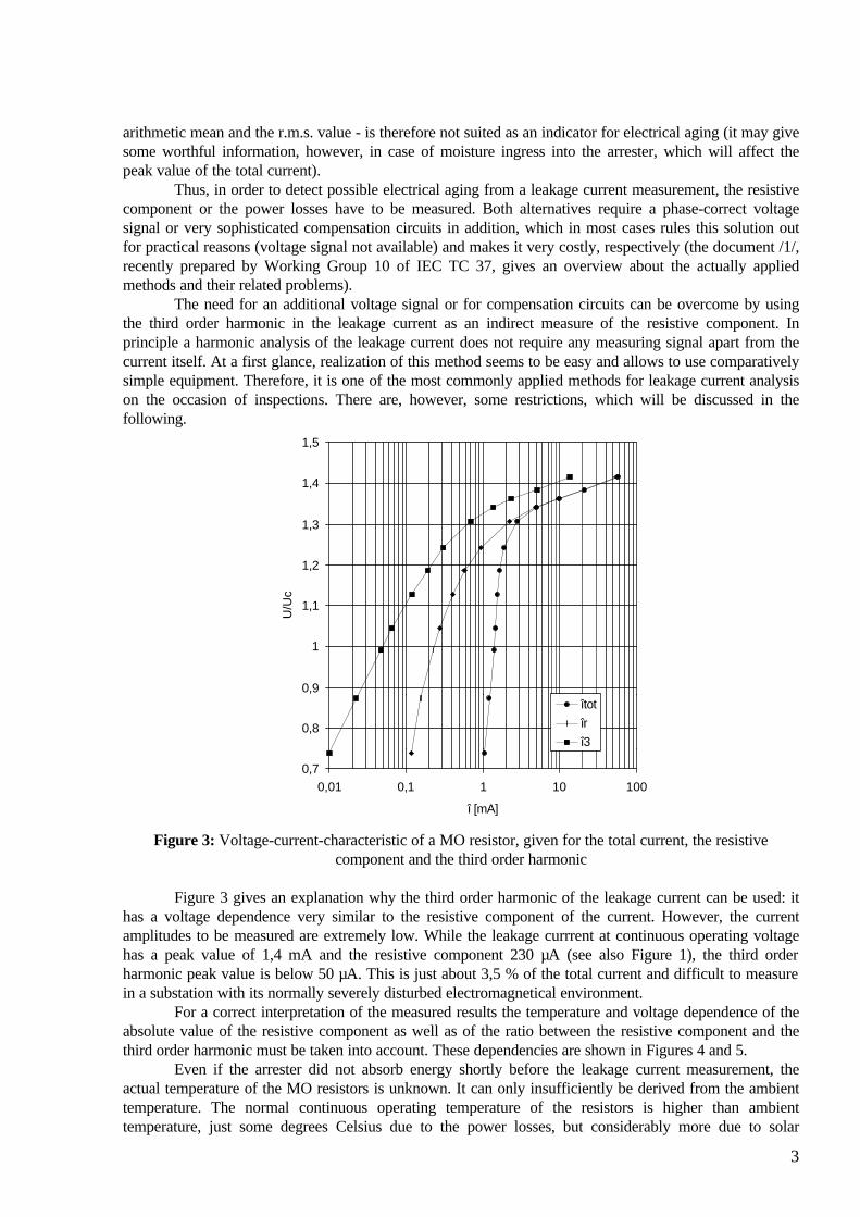
Figure 3: Voltage-current-characteristic of a MO resistor, given for the total current, the resistivecomponent and the third order harmonic
Figure 3 gives an explanation why the third order harmonic of the leakage current can be used: ithas a voltage dependence very similar to the resistive component of the current. However, the currentamplitudes to be measured are extremely low. While the leakage currrent at continuous operating voltagehas a peak value of 1,4 mA and the resistive component 230 µA (see also Figure 1), the third orderharmonic peak value is below 50 µA. This is just about 3,5 % of the total current and difficult to measurein a substation with its normally severely disturbed electromagnetical environment.
For a correct interpretation of the measured results the temperature and voltage dependence of theabsolute value of the resistive component as well as of the ratio between the resistive component and thethird order harmonic must be taken into account. These dependencies are shown in Figures 4 and 5.
Even if the arrester did not absorb energy shortly before the leakage current measurement, theactual temperature of the MO resistors is unknown. It can only insufficiently be derived from the ambienttemperature. The normal continuous operating temperature of the resistors is higher than ambienttemperature, just some degrees Celsius due to the power losses, but considerably more due to solar

4
radiation or discharge activities on the insulator surface under polluted conditions (the operating duty testof IEC 99-4 therefore starts with a temperature of 60 °C, which shall take these possible influences intoaccount). As it can be seen from Figure 4, a temperature increase from 20 °C to 60 °C will rise theresistive component of the leakage current by about 70% and the third order harmonic by about 50%. Sothe absolute values as well as the ratio between them change with temperature. This leads to intrinsicuncertainties for the third order harmonic analysis, where the real MO resistor temperature is unknown.
0
2
4
6
8
10
12
-40 -20 0 20 40 60 80 100 120 140
Temperature [°C]
îr /
îr(2
0°C
), î3
/ î3
(20°
C)
îr / îr (20ºC)
î3 / î3 (20ºC)
Figure 4: Temperature dependence of the resistive component and the third order harmonic in the leakagecurrent
0
0,5
1
1,5
2
2,5
3
3,5
0,40 0,50 0,60 0,70 0,80 0,90 1,00 1,10 1,20
U/Uc
îr /
îr(U
c), î
3 / î
3(U
c)
î3/î3(Uc)
îr/îr(Uc)
Figure 5: Voltage dependence of the resistive component and the third order harmonic in the leakagecurrent
Another, perhaps the major problem of the harmonic analysis is the third order harmonic content ofthe voltage, which is also unknown during the measurement, and which is the reason for the highestmeasurement uncertainties. A rough estimation gives an idea about the problem: a third order harmoniccontent of 1% in the voltage will cause 3% of third order harmonics in the linear capacitive component ofthe leakage current. Using the example of Figure 1, where the capacitive component (which is nearlyidentical with the total leakage current peak value) is 1,4 mA, the third order harmonic caused by theharmonics in the voltage has a peak value of 42 µA. This nearly equals the third order harmonic caused bythe non-linear resistance, which for this example is a little bit less than 50 µA. Since the phase angle of the
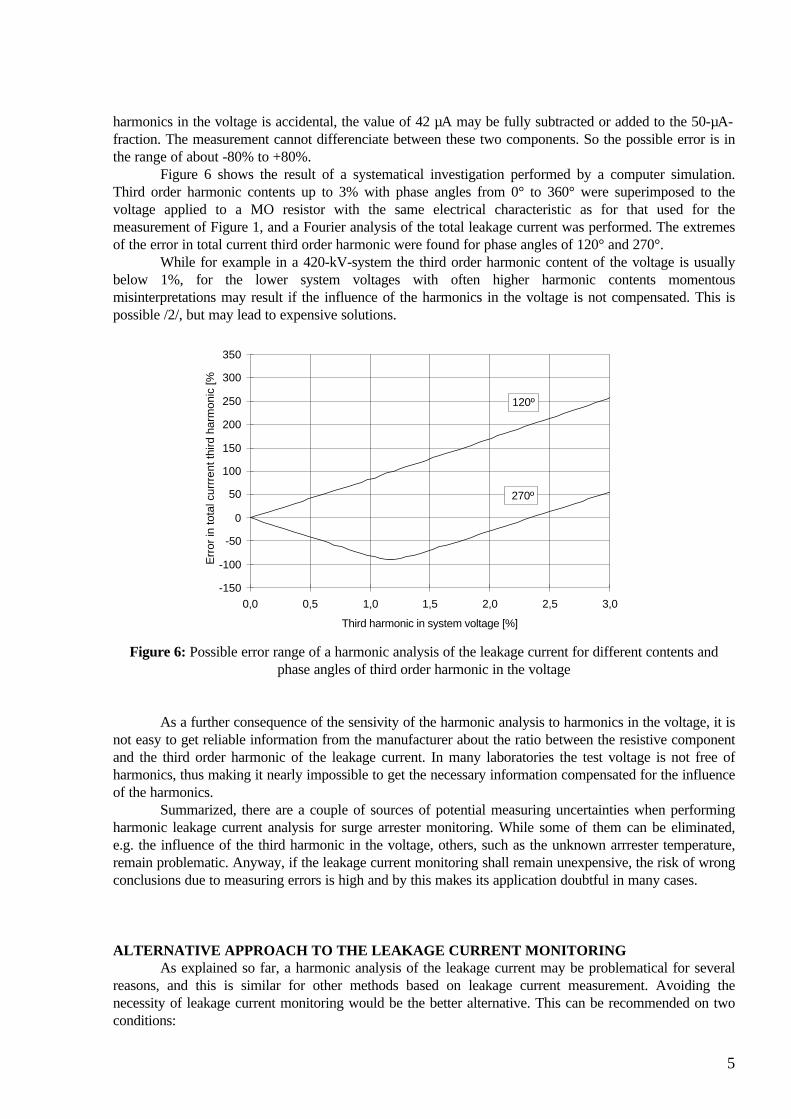
5
harmonics in the voltage is accidental, the value of 42 µA may be fully subtracted or added to the 50-µA-fraction. The measurement cannot differenciate between these two components. So the possible error is inthe range of about -80% to +80%.
Figure 6 shows the result of a systematical investigation performed by a computer simulation.Third order harmonic contents up to 3% with phase angles from 0° to 360° were superimposed to thevoltage applied to a MO resistor with the same electrical characteristic as for that used for themeasurement of Figure 1, and a Fourier analysis of the total leakage current was performed. The extremesof the error in total current third order harmonic were found for phase angles of 120° and 270°.
While for example in a 420-kV-system the third order harmonic content of the voltage is usuallybelow 1%, for the lower system voltages with often higher harmonic contents momentousmisinterpretations may result if the influence of the harmonics in the voltage is not compensated. This ispossible /2/, but may lead to expensive solutions.
-150
-100
-50
0
50
100
150
200
250
300
350
0,0 0,5 1,0 1,5 2,0 2,5 3,0
Third harmonic in system voltage [%]
Err
or in
tota
l cur
rren
t thi
rd h
arm
onic
[%]
120º
270º
Figure 6: Possible error range of a harmonic analysis of the leakage current for different contents andphase angles of third order harmonic in the voltage
As a further consequence of the sensivity of the harmonic analysis to harmonics in the voltage, it isnot easy to get reliable information from the manufacturer about the ratio between the resistive componentand the third order harmonic of the leakage current. In many laboratories the test voltage is not free ofharmonics, thus making it nearly impossible to get the necessary information compensated for the influenceof the harmonics.
Summarized, there are a couple of sources of potential measuring uncertainties when performingharmonic leakage current analysis for surge arrester monitoring. While some of them can be eliminated,e.g. the influence of the third harmonic in the voltage, others, such as the unknown arrrester temperature,remain problematic. Anyway, if the leakage current monitoring shall remain unexpensive, the risk of wrongconclusions due to measuring errors is high and by this makes its application doubtful in many cases.
ALTERNATIVE APPROACH TO THE LEAKAGE CURRENT MONITORINGAs explained so far, a harmonic analysis of the leakage current may be problematical for several
reasons, and this is similar for other methods based on leakage current measurement. Avoiding thenecessity of leakage current monitoring would be the better alternative. This can be recommended on twoconditions:
6
1) Electrical aging under continuous operating conditions can surely be excluded by adequate longtime stability tests during development and particularly in the running production of the MO resistors.
2) The arrester is checked for possible excessive impulse stresses, which may lead to impulsedegradation.
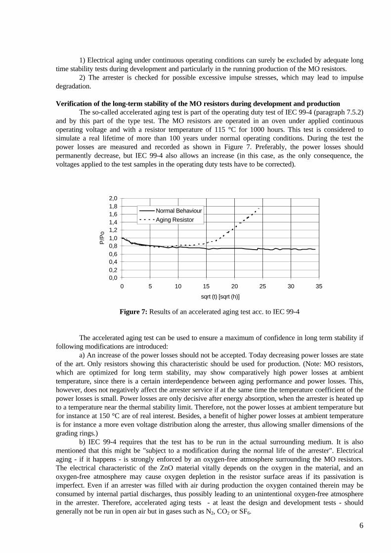
Verification of the long-term stability of the MO resistors during development and productionThe so-called accelerated aging test is part of the operating duty test of IEC 99-4 (paragraph 7.5.2)
and by this part of the type test. The MO resistors are operated in an oven under applied continuousoperating voltage and with a resistor temperature of 115 °C for 1000 hours. This test is considered tosimulate a real lifetime of more than 100 years under normal operating conditions. During the test thepower losses are measured and recorded as shown in Figure 7. Preferably, the power losses shouldpermanently decrease, but IEC 99-4 also allows an increase (in this case, as the only consequence, thevoltages applied to the test samples in the operating duty tests have to be corrected).
0,00,20,40,60,81,01,21,41,61,82,0
0 5 10 15 20 25 30 35
sqrt (t) [sqrt (h)]
P/P
o
Normal Behaviour
Aging Resistor
Figure 7: Results of an accelerated aging test acc. to IEC 99-4
The accelerated aging test can be used to ensure a maximum of confidence in long term stability iffollowing modifications are introduced:
a) An increase of the power losses should not be accepted. Today decreasing power losses are stateof the art. Only resistors showing this characteristic should be used for production. (Note: MO resistors,which are optimized for long term stability, may show comparatively high power losses at ambienttemperature, since there is a certain interdependence between aging performance and power losses. This,however, does not negatively affect the arrester service if at the same time the temperature coefficient of thepower losses is small. Power losses are only decisive after energy absorption, when the arrester is heated upto a temperature near the thermal stability limit. Therefore, not the power losses at ambient temperature butfor instance at 150 °C are of real interest. Besides, a benefit of higher power losses at ambient temperatureis for instance a more even voltage distribution along the arrester, thus allowing smaller dimensions of thegrading rings.)
b) IEC 99-4 requires that the test has to be run in the actual surrounding medium. It is alsomentioned that this might be "subject to a modification during the normal life of the arrester". Electricalaging - if it happens - is strongly enforced by an oxygen-free atmosphere surrounding the MO resistors.The electrical characteristic of the ZnO material vitally depends on the oxygen in the material, and anoxygen-free atmosphere may cause oxygen depletion in the resistor surface areas if its passivation isimperfect. Even if an arrester was filled with air during production the oxygen contained therein may beconsumed by internal partial discharges, thus possibly leading to an unintentional oxygen-free atmospherein the arrester. Therefore, accelerated aging tests - at least the design and development tests - shouldgenerally not be run in open air but in gases such as N2, CO2 or SF6.

7
c) The accelerated aging test should not just be performed during design and development of theMO resistors, but also as a sample test of each batch during running production.
If long-term stability of the MO resistors is verified as described before, there is only a negligiblerisk of electrical aging under continuous operating conditions. Investigations - some results are given inFigures 8 and 9 - have shown that even those resistors of an arrester, which are stressed by higher voltagesand temperatures due to an uneven voltage distribution along the arrester, are not endangered. Bothelevated temperatures and elevated operating voltages will cause an acceleration in the change of theelectrical characteristic in the leakage current region. Performance improvement as well as degradationeffects will be enforced. If the power losses tend to decrease under "normal" operating conditions they willdo in the same way but much faster under higher temperatures and/or operating voltages (vice versa,resistors with increasing power losses would show the same behaviour but much more intensified).
t [ h ]
P/P0
0
0,2
0,4
0,6
0,8
1
0 200 400 600 800 1000 1200
115°C130°C150°C
Figure 8: Accelerated aging test with U = Uc at different temperatures
t [ h ]
P/Po
0
0,2
0,4
0,6
0,8
1
0 200 400 600 800 1000 1200
U = 1.25 Uc U = 1.20 Uc
U = 1.15 Uc U = Uc
Figure 9: Accelerated aging test with ϑ = 115 °C and different voltages
Surge counters and monitoring spark gapsIt was shown what can be done by the manufacturer to exclude electrical aging of the MO
resistors. If these points are followed there is no reason for a continuous or regular leakage currentmonitoring in service. It will be very useful and important, however, to get information about the impulseenergy stresses applied to the arrester. In case of an obvious energy overstress (which is a very unlikelyevent) the manufacturer should be contacted. It may then be recommended to check the arrester off-line, for
8
example by recording the complete voltage-current-characteristic, which will give a clear indication if thearrester definitely has to be exchanged or not.
Though information about energy stresses cannot be given by surge counters, some words aboutthese devices shall be spent in this place. Surge counters are extensively used, since they are unexpensive,easy to install and easy to use. The value of their information, however, is limited, since surge counters justindicate if something "happened" or not. No further conclusion can be drawn about the severeness of theevents. High readings might cause more irritation than real information about arrester stresses. In order toavoid unnessecary worries, the sensitivity of counters should be chosen to reasonable values. There is noneed to count currents far below 100 A. Reasonable values (i.e. such values, which represent the lowerlimits of noticeable arrester stresses) are for instance 1 kA for lightning impulse currents 8/20 µs, 200 Afor switching impulse currents 30/60 µs and 100 A for long duration impulse currents.
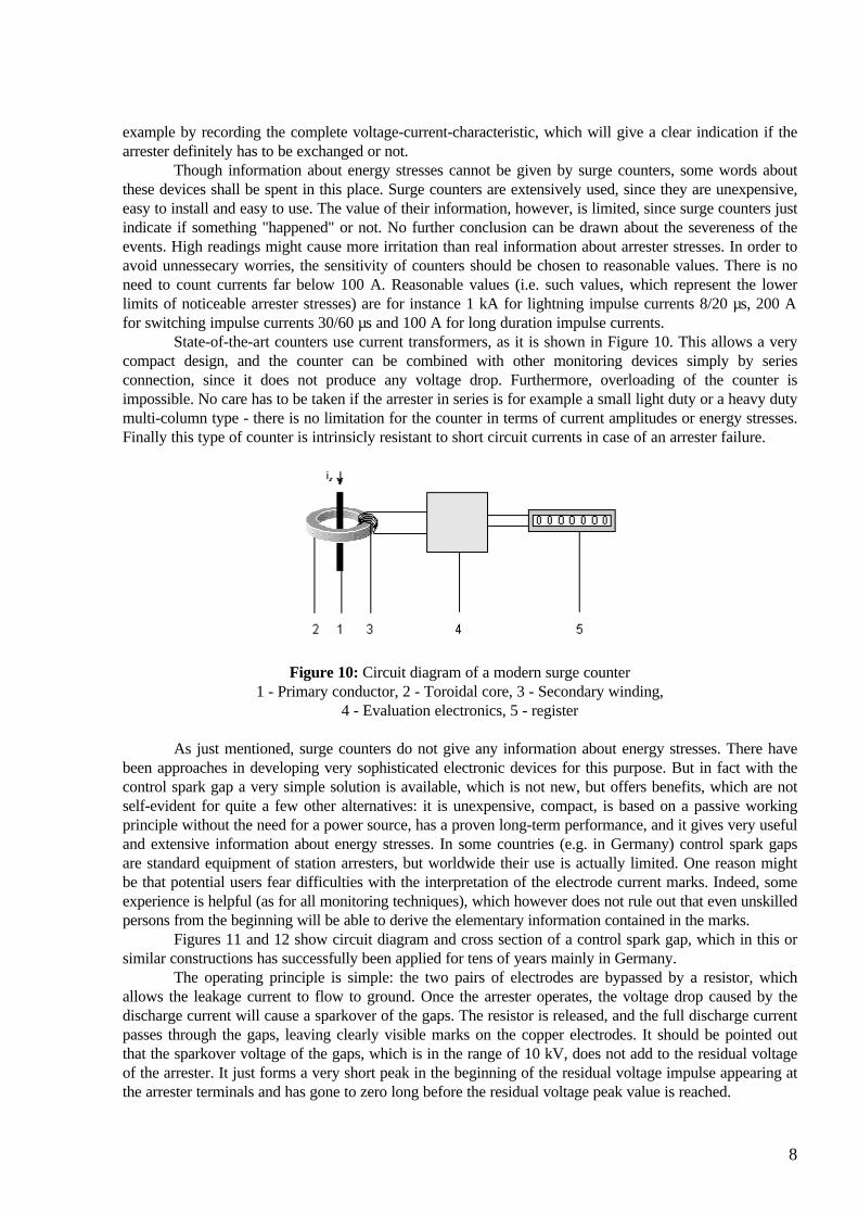
State-of-the-art counters use current transformers, as it is shown in Figure 10. This allows a verycompact design, and the counter can be combined with other monitoring devices simply by seriesconnection, since it does not produce any voltage drop. Furthermore, overloading of the counter isimpossible. No care has to be taken if the arrester in series is for example a small light duty or a heavy dutymulti-column type - there is no limitation for the counter in terms of current amplitudes or energy stresses.Finally this type of counter is intrinsicly resistant to short circuit currents in case of an arrester failure.
Figure 10: Circuit diagram of a modern surge counter1 - Primary conductor, 2 - Toroidal core, 3 - Secondary winding,
4 - Evaluation electronics, 5 - register
As just mentioned, surge counters do not give any information about energy stresses. There havebeen approaches in developing very sophisticated electronic devices for this purpose. But in fact with thecontrol spark gap a very simple solution is available, which is not new, but offers benefits, which are notself-evident for quite a few other alternatives: it is unexpensive, compact, is based on a passive workingprinciple without the need for a power source, has a proven long-term performance, and it gives very usefuland extensive information about energy stresses. In some countries (e.g. in Germany) control spark gapsare standard equipment of station arresters, but worldwide their use is actually limited. One reason mightbe that potential users fear difficulties with the interpretation of the electrode current marks. Indeed, someexperience is helpful (as for all monitoring techniques), which however does not rule out that even unskilledpersons from the beginning will be able to derive the elementary information contained in the marks.
Figures 11 and 12 show circuit diagram and cross section of a control spark gap, which in this orsimilar constructions has successfully been applied for tens of years mainly in Germany.
The operating principle is simple: the two pairs of electrodes are bypassed by a resistor, whichallows the leakage current to flow to ground. Once the arrester operates, the voltage drop caused by thedischarge current will cause a sparkover of the gaps. The resistor is released, and the full discharge currentpasses through the gaps, leaving clearly visible marks on the copper electrodes. It should be pointed outthat the sparkover voltage of the gaps, which is in the range of 10 kV, does not add to the residual voltageof the arrester. It just forms a very short peak in the beginning of the residual voltage impulse appearing atthe arrester terminals and has gone to zero long before the residual voltage peak value is reached.
9
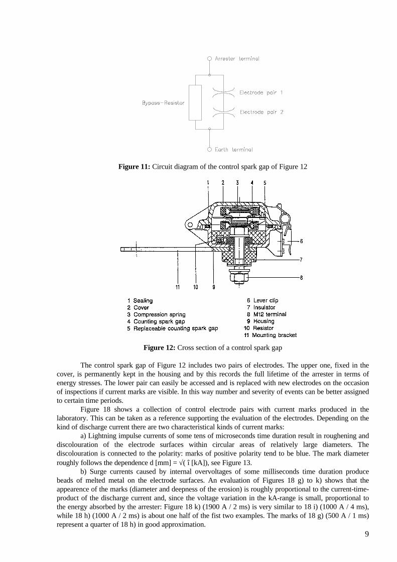
Figure 11: Circuit diagram of the control spark gap of Figure 12
Figure 12: Cross section of a control spark gap
The control spark gap of Figure 12 includes two pairs of electrodes. The upper one, fixed in thecover, is permanently kept in the housing and by this records the full lifetime of the arrester in terms ofenergy stresses. The lower pair can easily be accessed and is replaced with new electrodes on the occasionof inspections if current marks are visible. In this way number and severity of events can be better assignedto certain time periods.
Figure 18 shows a collection of control electrode pairs with current marks produced in thelaboratory. This can be taken as a reference supporting the evaluation of the electrodes. Depending on thekind of discharge current there are two characteristical kinds of current marks:
a) Lightning impulse currents of some tens of microseconds time duration result in roughening anddiscolouration of the electrode surfaces within circular areas of relatively large diameters. Thediscolouration is connected to the polarity: marks of positive polarity tend to be blue. The mark diameterroughly follows the dependence d [mm] = √( î [kA]), see Figure 13.
b) Surge currents caused by internal overvoltages of some milliseconds time duration producebeads of melted metal on the electrode surfaces. An evaluation of Figures 18 g) to k) shows that theappearence of the marks (diameter and deepness of the erosion) is roughly proportional to the current-time-product of the discharge current and, since the voltage variation in the kA-range is small, proportional tothe energy absorbed by the arrester: Figure 18 k) (1900 A / 2 ms) is very similar to 18 i) (1000 A / 4 ms),while 18 h) (1000 A / 2 ms) is about one half of the fist two examples. The marks of 18 g) (500 A / 1 ms)represent a quarter of 18 h) in good approximation.

10
0
0,5
1
1,5
2
2,5
3
3,5
4
0 1 2 3 4 5 6 7 8 9 10
Lightning impulse current [kA]
Dia
met
er o
f cur
rent
mar
k [m
m]
Figure 13: Diameter range of current marks for lightning impulse currents
In the following, three examples of control electrodes taken from real service are presented:Figure 14: Electrodes of an arrester for the protection of the transformer neutral in a resonant
earthed 123-kV-system. About 25 current marks of max. 100 A can be detected, which are caused by thetransient oscillations during an intermittent earth fault. The arrester stress was negligible, hence there is noreason for a further check of the arrester performance.
Figure 14: Example of control electrodes from service (123 kV; negligible stress)
Figure 15: Example of control electrodes from service (back-to-back station; negligible stress)
11
Figure 15: Electrodes of a valve protection arrester in a back-to-back converter station. Theseelectrodes show about 15 marks of switching impulse currents in the range 100...200 A / 1 ms. Though thestresses for the arrester are negligible, this result may give reason for further investigations about possibleabnormal operating conditions of the valves. This is also an example for a very simple solution of a seriousproblem: valve protection arresters are operated at high potential making galvanic connections to earthimpossible. Monitoring of arresters by electronic devices can lead to very expensive solutions.
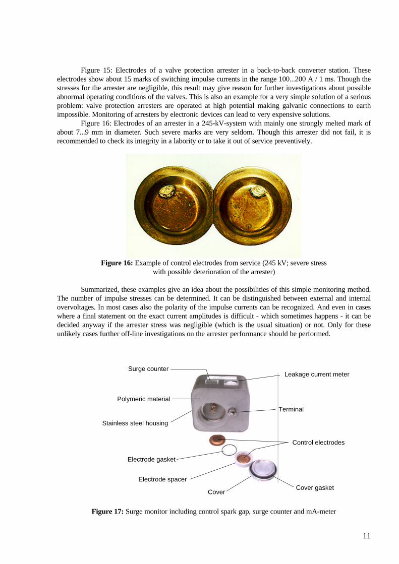
Figure 16: Electrodes of an arrester in a 245-kV-system with mainly one strongly melted mark ofabout 7...9 mm in diameter. Such severe marks are very seldom. Though this arrester did not fail, it isrecommended to check its integrity in a labority or to take it out of service preventively.
Figure 16: Example of control electrodes from service (245 kV; severe stresswith possible deterioration of the arrester)
Summarized, these examples give an idea about the possibilities of this simple monitoring method.The number of impulse stresses can be determined. It can be distinguished between external and internalovervoltages. In most cases also the polarity of the impulse currents can be recognized. And even in caseswhere a final statement on the exact current amplitudes is difficult - which sometimes happens - it can bedecided anyway if the arrester stress was negligible (which is the usual situation) or not. Only for theseunlikely cases further off-line investigations on the arrester performance should be performed.
Leakage current meterSurge counter
Terminal
Control electrodes
Electrode gasket
Electrode spacer
CoverCover gasket
Stainless steel housing
Polymeric material
Figure 17: Surge monitor including control spark gap, surge counter and mA-meter

12
Figure 18: Examples of current marks on control electrodes

13
In order to combine the control spark gap with the often required surge counter and mA-meter,newer very compact devices, including all these components in one housing, have been developed. Anexample is shown in Figure 17. It is part of a modular system, which brings together the benefits of controlelectrodes with the actual demands of users for low cost, easy-to-use monitoring devices.
CONCLUSIONThough most MO surge arresters have shown excellent long time performance for more than 15
years, monitoring is often required in order to detect possible electrical aging.Third order harmonic analysis of the leakage current, which is a common practice, bears a high
risk of measuring errors and often gives rise to misinterpretations.If, however, MO resistors are used, which are developed particularly with regard to long-term
stability, if this is verified by adequate verification procedures both during development and the runningproduction, and if the arresters are designed to avoid excessive stresses for the resistors like internal partialdischarges, there is no need to invest in costly on-line monitoring systems.
Nevertheless, it is very important to get information about the impulse energy stresses applied tothe arrester. In case of an obvious energy overstress the manufacturer should be contacted. It may then berecommended to check the arrester off-line, for example by recording the complete voltage-current-characteristic, which will give a clear indication if the arrester definitely has to be exchanged or not.
Monitoring of impulse energy stresses can very effectively be realized by control spark gaps, whichare unjustly not very popular so far. Control spark gaps are unexpensive, compact, are based on a passiveworking principle without the need for a power source, have a proven long-term performance and giveextensive information about energy stresses applied to the arrester. A wider application of control sparkgaps for arrester monitoring would be reasonable and useful.
REFERENCES/1/ IEC document 37/162/CD, July 1996: Diagnostic indicators of metal-oxide arresters in service/2/ J. Lundquist, L. Stenström, A. Schei, B. Hansen
New Method for Measurement of the Resistive Leakage Currents of Metal-OxideSurge Arresters in ServiceIEEE Trans. on PWRD, Vol. 5, No. 4, November 1990

Volker Hinrichsen
Monitoring of High Voltage Metal Oxide Surge Arresters
paper presented at
VI Jornadas Internacionales de Aislamiento EléctricoBilbao, 22./23.10.1997, Paper 6.4