monitoring plan template for drinking water … · c. summary of treatment plants 8 d. summary of...
TRANSCRIPT

Environmental Protection Agency Region 8 Office of Partnerships & Regulatory Assistance Water Program Attn: Drinking Water Unit (Mail Code: 8P-W-DW) 1595 Wynkoop Street Denver, CO 80202-1129 Business Hours Contact: 1- 800-227-8917 Emergency After-Hours Contact: 303-312-6327 FAX Number: 303-312-6131 ___________________________________________________________________________
Monitoring Plan Template
For
Drinking Water
Disinfectants and Disinfection Byproducts Rule
&
Interim Enhanced Surface Water Treatment Rule
December 2003
This Template is provided by the Environmental Protection Agency in Region 8 for Public Water Systems to use to prepare their Monitoring Plans for the D/DBPR and LT1ESWTR. This document provides guidance to public water systems. The document is not, however, the actual Environmental Protection Agency regulation, nor is it a regulation itself. The actual regulation can be found in 40 CFR (Code of Federal Regulations) Part 141.

PWSID# System Name Date of Plan
Monitoring Plan Template—December 2003 2
Table of Contents
Page Number INTRODUCTION 3 PART I –Monitoring Plan Summary Sheet 6
A. Summary of System Information 8 B. Summary of Water Sources 8 C. Summary of Treatment Plants 8 D. Summary of Distribution System 8
PART II – Water Sources Details 9
A. Inventory of Water Sources 11 B. Sketch of Water Sources 13 C. Additional Information 14
PART III – Water Treatment Details 15
A. Treatment Plant Information 17 B. Process Schematic of the Water Treatment Plant 19 C. List of Chemicals Used in Each Treatment Plant 20 D. Additional Information 20
Part IV – Distribution System Details 21
A. Residence Times 23 B. Entry Points to the Distribution System 23 C. Sketch of the Distribution System 24 D. Water Wholesalers 25 E. Additional Information 26
Part V –Monitoring Plans 27
A. Disinfectants and Disinfection Byproducts Rule 28 B. Enhanced Surface Water Treatment Rules 42

PWSID# System Name Date of Plan
Monitoring Plan Template—December 2003 3
Introduction
For the Disinfectants and Disinfection Byproducts Rule (D/DBPR), each water system must develop a monitoring plan to show how a system intends to comply with the monitoring requirements of the Rule. The monitoring plan serves as a uniquely tailored roadmap for each specific system to demonstrate that the water quality self-monitoring performed by the system is representative of the water distributed to consumers and is consistent with regulatory requirements.
Submission to Environmental Protection Agency Region 8 Submit one (1) copy of the final monitoring plan to: Environmental Protection Agency Region 8 Office of Partnerships & Regulatory Assistance
Stage 1 DBPR Rule Manager Mail Code: 8P-W-DW 1595 Wynkoop Street
Denver, CO 80202-1129
Revisions Submit a revised Monitoring Plan Summary Sheet with each element revision to the above address.
Monitoring Plan Required Content Elements PART I The Monitoring Plan Summary Sheet identifies the public water system and provides relevant
information. Following the Summary Sheet, the monitoring plan consists of the following sections that fully describe the characteristics of the system. PART II Water Sources Details identifies all water sources used by the system. PART III Water Treatment Details summarizes the system’s operating characteristics, treatment trains
and their associated temporal distribution that was assumed in the design of the monitoring plan (e.g., use of maximum capacity facilities, alternative water sources, maintenance schedules that take facilities off line, etc.).
PART IV Distribution System Details provides a schematic of the distribution system with all sources,
entry points, post entry point treatment facilities, storage facilities and monitoring points.

PWSID# System Name Date of Plan
Monitoring Plan Template—December 2003 4
Based on the specific information provided in Parts II-IV, the specific monitoring program for D/DBPR and LT1ESWTR is developed and justified in Part V, Sections A&B. PART V Monitoring Plans provides a detailed plan for the monitoring of D/DBPR and LT1ESWTR for
which a compliance determination is required including: • Frequency and approximate time of collection • Sample site location identification and associated identification number • If appropriate, justification for the site selection • Sample preservation requirements • Analysis procedure (certified laboratory or on-site by party approved by EPA) • Monitoring results presentation format • Procedures to assess and report compliance status for MCLs, MRDLs, TTs and TOC removal
efficiency. • The rationale used by the system to identify the sampling locations selected to represent the
distribution system. • A process to review and update the selected distribution system sampling locations to account for
changes due to growth or other significant changes to the distribution system.

PWSID# System Name Date of Plan
Monitoring Plan Template—December 2003 5
Drinking Water Monitoring Plan System Name
PWSID #

PWSID# System Name Date of Plan
Monitoring Plan Template—December 2003 6
PART I
MONITORING PLAN SUMMARY
1. Instructions for Completing the Monitoring Plan Summary Sheet
2. Monitoring Plan Summary Sheet Summary of System Information
Summary of Water Sources
Summary of Treatment Plants
Summary of Distribution System
PWSID# System Name Date of Plan
Monitoring Plan Template—December 2003 7
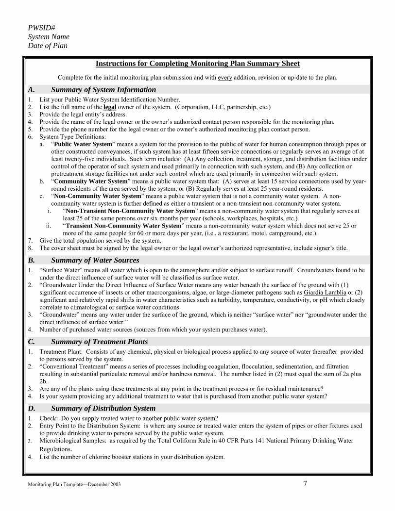
Instructions for Completing Monitoring Plan Summary Sheet
Complete for the initial monitoring plan submission and with every addition, revision or up-date to the plan.
A. Summary of System Information 1. List your Public Water System Identification Number. 2. List the full name of the legal owner of the system. (Corporation, LLC, partnership, etc.) 3. Provide the legal entity’s address. 4. Provide the name of the legal owner or the owner’s authorized contact person responsible for the monitoring plan. 5. Provide the phone number for the legal owner or the owner’s authorized monitoring plan contact person. 6. System Type Definitions:
a. “Public Water System” means a system for the provision to the public of water for human consumption through pipes or other constructed conveyances, if such system has at least fifteen service connections or regularly serves an average of at least twenty-five individuals. Such term includes: (A) Any collection, treatment, storage, and distribution facilities under control of the operator of such system and used primarily in connection with such system, and (B) Any collection or pretreatment storage facilities not under such control which are used primarily in connection with such system.
b. “Community Water System” means a public water system that: (A) serves at least 15 service connections used by year-round residents of the area served by the system; or (B) Regularly serves at least 25 year-round residents.
c. “Non-Community Water System” means a public water system that is not a community water system. A non-community water system is further defined as either a transient or a non-transient non-community water system.
i. “Non-Transient Non-Community Water System” means a non-community water system that regularly serves at least 25 of the same persons over six months per year (schools, workplaces, hospitals, etc.).
ii. “Transient Non-Community Water System” means a non-community water system which does not serve 25 or more of the same people for 60 or more days per year, (i.e., a restaurant, motel, campground, etc.).
7. Give the total population served by the system. 8. The cover sheet must be signed by the legal owner or the legal owner’s authorized representative, include signer’s title.
B. Summary of Water Sources 1. “Surface Water” means all water which is open to the atmosphere and/or subject to surface runoff. Groundwaters found to be
under the direct influence of surface water will be classified as surface water. 2. “Groundwater Under the Direct Influence of Surface Water means any water beneath the surface of the ground with (1)
significant occurrence of insects or other macroorganisms, algae, or large-diameter pathogens such as Giardia Lamblia or (2) significant and relatively rapid shifts in water characteristics such as turbidity, temperature, conductivity, or pH which closely correlate to climatological or surface water conditions.
3. “Groundwater” means any water under the surface of the ground, which is neither “surface water” nor “groundwater under the direct influence of surface water.”
4. Number of purchased water sources (sources from which your system purchases water).
C. Summary of Treatment Plants 1. Treatment Plant: Consists of any chemical, physical or biological process applied to any source of water thereafter provided
to persons served by the system. 2. “Conventional Treatment” means a series of processes including coagulation, flocculation, sedimentation, and filtration
resulting in substantial particulate removal and/or hardness removal. The number listed in (2) must equal the sum of 2a plus 2b.
3. Are any of the plants using these treatments at any point in the treatment process or for residual maintenance? 4. Is your system providing any additional treatment to water that is purchased from another public water system?
D. Summary of Distribution System 1. Check: Do you supply treated water to another public water system? 2. Entry Point to the Distribution System: is where any source or treated water enters the system of pipes or other fixtures used
to provide drinking water to persons served by the public water system. 3. Microbiological Samples: as required by the Total Coliform Rule in 40 CFR Parts 141 National Primary Drinking Water
Regulations. 4. List the number of chlorine booster stations in your distribution system.

PWSID# System Name Date of Plan
Monitoring Plan Template—December 2003 8
5.
MONITORING PLAN SUMMARY SHEET A. Summary of System Information 1. PWSID Number: ________________________________________________________ 2. System Legal Name: _____________________________________________________ 3. Legal Address: __________________________________________________________ 4. E-mail Address: _________________________________________________________ 5. Legal Contact Name: _____________________________________________________ 6. Legal Contact’s Phone Number: ____________________________________________ 7. System Type: Community Non-Transient Non-Community 8. Total Population Served: ____________________
B. Summary of Water Sources Provide a sketch of all source locations in Part II 1. Number of Surface Water Sources: ___________ 2. Number of Ground Water Under the Direct Influence of Surface Water Sources: ___________ 3. Number of Ground Water Sources: ___________ 4. Number of Sources from which your system Purchases Water: __________
C. Summary of Treatment Plants Provide a block process schematic for each plant in Part III 1. Number of Treatment Plants: ____________ 2. Number of Treatment Plants using Conventional Treatment: ___________
a. Number Subject to Enhanced Coagulation: __________ b. Number Subject to Enhanced Softening: __________
3. Number of Treatment Plants Using one or more of the following at any point in the treatment process or for residual maintenance:
a. Free Chlorine: ___________ b. Chloramines: ___________ c. Chlorine Dioxide: ___________ d. Ozone: __________ e. Other disinfectant: __________
4. Do you provide additional treatment to any water purchased from another Public Water System? Yes No
D. Summary of Distribution System See schematic map supplied by EPA in Part IV
1. Does your system supply treated water to other systems? No Yes , provide details in Part IV If Yes, enter the total population served by these systems: _______________
2. Number of Entry Points to your Distribution System: ___________ 3. Number of Routine Microbiological Samples Submitted to EPA per Month: ___________ 4. Number of Chlorine Booster Stations in your Distribution System: _____________________ _________________________________________________________________ ________________________________ Signature of Owner or Authorized Representative and Title Date

PWSID# System Name Date of Plan
Monitoring Plan Template—December 2003 9
PART II WATER SOURCES DETAILS
1. Instructions for Completing Part II—Water Sources Details
2. Inventory of Water Sources
3. Sketch of Water Sources
4. Additional Information

PWSID# System Name Date of Plan
Monitoring Plan Template—December 2003 10
Instructions for Completing PART II –Water Sources Details
A. Inventory of Water Sources
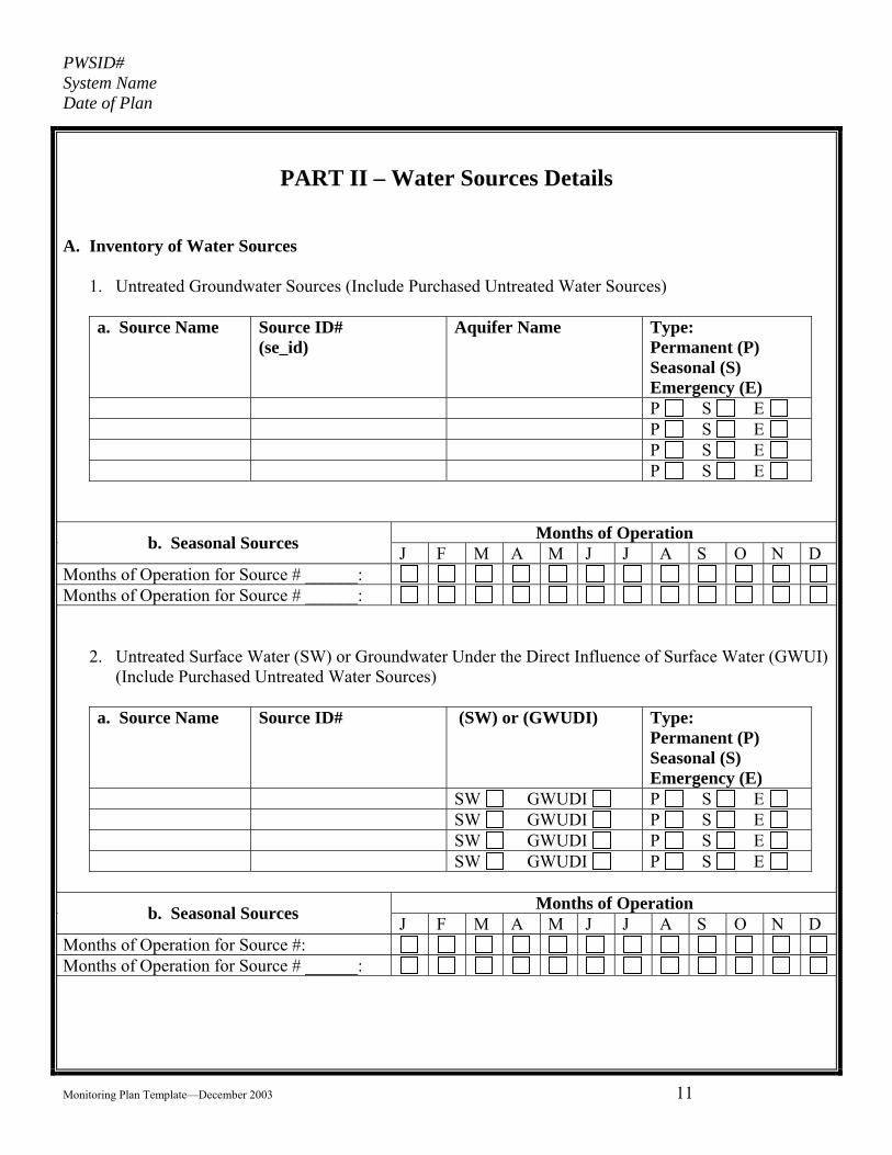
1. For all groundwater sources, including emergency sources list the: a. Source names b. Source ID numbers* c. Aquifer name (if known) d. Source type (P-permanent, S-seasonal, or E-emergency).
2. For all surface water (SW) or groundwater under the direct influence of surface water (GWUDI) sources, including seasonal and/or emergency sources: a. For each untreated surface water source, including seasonal, emergency or purchased sources
please provide the following information: i. List each source by name and source ID* number ii. Identify the sources as SW or GWUDI. iii. Identify the sources that are used seasonally. iv. Identify the sources that are used only for emergencies.
b. For those sources that are listed as seasonal, provide the i. Source name and source ID number. ii. The usual or expected months of operation
3. For each source of treated purchased water: a. List the type(s)of additional treatment provided for each source if any, if none so indicate. Provide a full explanation of the treatment processes in Part III; or b. Certify whether your system has an agreement with each supplier to monitor water quality for
you. If so, indicate which rules are covered by the agreement.
Expand or contract each table as necessary.
B. Schematic Map of Water Sources (supplied by EPA and modify the schematic if necessary)
1. Review and verify each source by Source ID number. 2. Review the schematic and verify how the sources connect to any headers, storage tanks and to the
water treatment plant(s) and show the relative distances between components. Label lines with approximate lengths between components.
C. Additional Information Modify the schematic map supplied by EPA to include any additional information that would be helpful to understanding your water source(s) and how they are operated within your overall production scheme.
PWSID# System Name Date of Plan
Monitoring Plan Template—December 2003 11
PART II – Water Sources Details
A. Inventory of Water Sources
1. Untreated Groundwater Sources (Include Purchased Untreated Water Sources)
a. Source Name Source ID# (se_id)
Aquifer Name Type: Permanent (P) Seasonal (S) Emergency (E)
P S E P S E P S E P S E
Months of Operation b. Seasonal Sources J F M A M J J A S O N D Months of Operation for Source # ______: Months of Operation for Source # ______:
2. Untreated Surface Water (SW) or Groundwater Under the Direct Influence of Surface Water (GWUI) (Include Purchased Untreated Water Sources)
a. Source Name Source ID# (SW) or (GWUDI) Type:
Permanent (P) Seasonal (S) Emergency (E)
SW GWUDI P S E SW GWUDI P S E SW GWUDI P S E SW GWUDI P S E
Months of Operation b. Seasonal Sources J F M A M J J A S O N D
Months of Operation for Source #: Months of Operation for Source # ______:

PWSID# System Name Date of Plan
Monitoring Plan Template—December 2003 12
3. Purchased Treated Water Received by your System
Rules Covered by the Agreement
Supplier System Name
Supplier PWSID Number
Additional Treatment Applied
Type(s) of Treatment Applied*
Written Agreement for Supplier to Monitor Your Water Quality
TC* IOC* OC* R* Pb/ Cu*
D/ DBP*
IE*
YES NO
YES NO
YES NO
YES NO
YES NO
YES NO
YES NO
YES NO
* See Table 1 Part III A. Treatment Process Code Table Legend
Microbiological = TC Inorganic Chemicals = IOC Organic Chemicals = OC Radionuclides = R Lead and Copper = Pb/Cu Disinfectants and Disinfection Byproducts = DDBP Interim Enhanced Surface Water Treatment = IE

PWSID# System Name Date of Plan
Monitoring Plan Template—December 2003 13
B. Schematic Map of Water Sources—(supplied by EPA)
Schematic Map of each PWS.

PWSID# System Name Date of Plan
Monitoring Plan Template—December 2003 14
C. Additional Information (If appropriate.)

PWSID# System Name Date of Plan
Monitoring Plan Template—December 2003 15
PART III
Water Treatment Details
1. Instructions for Completing Part III—Water Treatment Details
2. Treatment Plant Information
3. Process Schematic of the Water Treatment Plant
4. Additional Information

PWSID# System Name Date of Plan
Monitoring Plan Template—December 2003 16
Instructions for Completing PART III –Water Treatment Details
A. Treatment Plant Information
NOTE: In the event treatment is provided at each well source rather than at a centralized treatment plant, depict each of the treatment processes on the source sketch in section B, combining the sketches for sources and treatment in one sketch or provide a schematic of each treatment process applied at each of the individual sources.
Complete for each Water Treatment Plant 1. Treatment Plant Name 2. Treatment Plant ID number* 3. Contributing sources ID* number 4. Rated capacity in million gallons per day (MGD), or in gallons per minute (GPM) 5. Detail all treatment techniques used: See list of codes at end of section and enter all that apply to each
treatment plant. 6. Indicate any use of an oxidant for disinfection and for any other purpose.
B. Process Schematic of the Water Treatment Plant
1. Size — preferably no larger than 8 ½ x 14 inches 2. Prepare a separate schematic for each water treatment plant (WTP). 3. Show the points where any chemical is added within the treatment train and indicate the chemical
added. IF any chemical or physical pretreatment processes are used, include a similar schematic for each pretreatment train and indicate its location on the overall treatment schematic. If this is not feasible, show the pretreatment process locations on the source water schematic.
4. If your system has more than one treatment plant, indicate which sources supply each treatment plant. C. Additional Information
Include additional information that would be helpful to understanding your WTP or processes.

PWSID# System Name Date of Plan
Monitoring Plan Template—December 2003 17
PART III – Water Treatment Details
A. Treatment Plant Information
Treatment Plant Name
Treatment Plant ID #
Contributing Sources ID #
Rated Capacity (MGD, or GPM)
Treatment Process Codes List all that Apply*
* See Next Page for a list of Codes

PWSID# System Name Date of Plan
Monitoring Plan Template—December 2003 18
TABLE 1 - TREATMENT PROCESS CODE * 100 Activated Alumina 121 Activated Carbon, Granular 125 Activated Carbon, Powdered 141 Aeration, Cascade 143 Aeration, Diffused 145 Aeration, Packed Tower 147 Aeration, Slat Tray 149 Aeration, Spray 160 Algae Control 180 Bone Char 190 Brominization (Special Use) 200 Chloramines 220 Chlorine Dioxide 240 Coagulation 300 Distillation 320 Electrodialysis 341 Filtration, Cartridge or Bag 342 Filtration, Diatomaceous Earth 343 Filtration, Greensand 344 Filtration, Pressure Sand 345 Filtration, Rapid Sand 346 Filtration, Slow Sand 347 Filtration, Ultrafiltration or Microfiltration 348 Filtered 360 Flocculation 380 Fluoridation 401 Gaseous Chlorination, Post 403 Gaseous Chlorination, Pre
421 Hypochlorination, Post 423 Hypochlorination, Pre 441 Inhibitor, Bimetallic Phosphate 443 Inhibitor, Hexametaphosphate 445 Inhibitor, Orthophosphate 447 Inhibitor, Polyphosphate 449 Inhibitor, Silicate 455 Iodine 460 Ion Exchange 500 Lime - Soda Ash Addition 520 Microscreening 541 Ozonation, Post 543 Ozonation, Pre 560 Permanganate 580 Peroxide 600 Rapid Mix 620 Reducing Agents 623 Reducing Agent, Sodium Bisulfate 625 Reducing Agent, Sodium Sulfite 627 Reducing Agent, Sulfur Dioxide 640 Reverse Osmosis 660 Sedimentation 680 Sequestration 700 Sludge Treatment 720 Ultraviolet Radiation 740 Ph Adjustment 741 Ph Adjustment, Post 742 Ph Adjustment, Pre 999 Innovative
*12/11/2001,SAFE DRINKING WATER INFORMATION SYSTEM / FEDERAL (SDWIS/FED), PAGE 1

PWSID# System Name Date of Plan
Monitoring Plan Template—December 2003 19
B. Process Schematic of the Water Treatment Plant--—(Not necessary to be drawn to scale.)

PWSID# System Name Date of Plan
Monitoring Plan Template—December 2003 20
C. List all chemicals that are added in each treatment plant (and if applicable each pretreatment
facility). D. Additional Information (If appropriate.)

PWSID# System Name Date of Plan
Monitoring Plan Template—December 2003 21
Part IV
Distribution System Details
1. Instructions for Completing Part IV—Distribution System Details 2. Entry Points to the Distribution System 3. Sketch of the Distribution System 4. Water Wholesalers 5. Additional Information

PWSID# System Name Date of Plan
Monitoring Plan Template—December 2003 22
Instructions for Completing PART IV – Distribution System Details A. Distribution System Average and Maximum Residence Times
Explain the methodology used to determine the locations in the distribution system that represent average residence time and maximum residence time.
a.) Maximum residence times--Explain the criteria you used to make this determination and why it is appropriate. Identify any overlapping zones of influence that represent maximum distribution system residence times.
b.) Average residence times--Explain the criteria you used to make this determination and why it is appropriate. Identify areas in the distribution system where waters from two or more entry points are expected to mix or represent water from multiple entry points (overlapping zones of influence) and represent at least average residence time.
B. Entry Points to the Distribution System
Identify by number or code all entry points to the distribution system and their associated treatment plants, treated purchased sources and, if applicable, any untreated sources. C. Sketch of Distribution System—
(Use the schematic map supplied by EPA to depict relative features and distances.)
1. Include details: a. Locations representative of Maximum residence times and associated sampling locations b. Locations representative of Average residence times and associated sampling locations c. All Entry Points to the distribution system d. All treatment facilities within the distribution system, such as booster chlorination stations e. All storage facilities f. Overlapping zones of Influence g. Points of connection to other public water system(s) h. Identify all sampling locations by their sample location identifier number
D. Suppliers of Treated Water to other Public Water Systems
1. For each system that you provide with treated drinking water: a. List the system name and their Public Water System Identification number. b. The population served by each system.
2. Explain how your system is physically connected to the purchasing system and the plan to be used to ensure appropriate monitoring and water quality are achieved.
3. Explain your relationship, if any, to the purchasing system with respect to water quality monitoring or compliance within the purchasing system.
E. Additional Information
Include additional information that would be helpful to understanding your distribution system.

PWSID# System Name Date of Plan
Monitoring Plan Template—December 2003 23
PART IV – Distribution System Details
A. Residence Times Determination
1. Provide an explanation of the method(s) used to determine Maximum Distribution System Residence Time
2. Provide an explanation of the method(s) used to determine Average Distribution System Residence Time
3. Provide an explanation of how the distribution system first customer was determined (if applicable).
B. Entry Points to the Distribution System
1. Entry Point Designation Description
Name of the Contributing: Entry Point
Location Name
Entry Point
Location Identifier Treatment Plants Purchased Sources Untreated Sources
2. Evaluation and description of the extent to which Zones of Influence from each source overlap, if
applicable.

PWSID# System Name Date of Plan
Monitoring Plan Template—December 2003 24
C. Sketch of Distribution System

PWSID# System Name Date of Plan
Monitoring Plan Template—December 2003 25
D. Identify the Systems that Purchase Treated Water from your System
Rules Covered by the Agreement
Purchasing System Name
Purchasing System PWSID Number
Purchasing System Population Served
Written Agreement for Purchaser to be Integrated System
TC* IOC* OC* R* Pb/ Cu*
D/ DBP* IE*
YES NO
YES NO
YES NO
YES NO
* Table Legend
Microbiological = TC Inorganic Chemicals = IOC Organic Chemicals = OC Radionuclides = R Lead and Copper = Pb/Cu Disinfectants and Disinfection Byproducts = D/DBP Interim Enhanced Surface Water Treatment = IE

PWSID# System Name Date of Plan
Monitoring Plan Template—December 2003 26
E. Additional Information (If appropriate)

PWSID# System Name Date of Plan
Monitoring Plan Template—December 2003 27
Part V
Monitoring Plans
Section A Disinfectants and Disinfection Byproducts Rule
Section B Interim Enhanced Surface Water Treatment Rule

PWSID# System Name Date of Plan
Monitoring Plan Template—December 2003 28
Section A
Disinfectants and Disinfection Byproducts Rule
I. D/DBPR Monitoring Plan Summary i. Table of Treatment Processes ii. Summary of the System’s D/DBP Monitoring Plan Considerations iii. Summary of Monitoring Records Location and Maintenance
II. Disinfection Byproducts Monitoring i. Paired TTHM/HAA5 Distribution System Monitoring ii. Chlorite Monitoring (for Systems Using Chlorine Dioxide) iii. Bromate Monitoring (for Systems Using Ozone) iv. Disinfection Byproducts Reporting Forms
III. Maximum Residual Disinfectant Level (MRDL) Monitoring i. Chlorine or Chloramine Monitoring ii. Chlorine Dioxide Monitoring iii. Disinfectant Residual Sample Analysis iv. Disinfectant Residual Reporting Forms
IV. Disinfection Byproduct Precursors Monitoring – Conventional Filtration Only (if not different from information provided in Part IV-refer to Part IV rather than repeating the same information) i. Raw and Finished Water “Paired” Sampling Sites ii. “Paired” Sample Analysis for DBP Precursor Removal iii. Disinfection Byproduct Precursors Removal Reporting Forms

PWSID# System Name Date of Plan
Monitoring Plan Template—December 2003 29
I. D/DBPR Monitoring Plan Summary i. Table of Treatment Processes
Treatment Plant Name
Treatment Plant ID #
Associated Entry Point Location Identifier
Treatment Processes (circle the final filtration barrier)
Primary Disinfectant For microbial inactivation
Secondary Disinfectant-For maintaining disinfectant residual
Other Oxidants
Direct filtration Disinfection Conventional Softening GAC Membrane filtration Other
Free Chlorine Chloramines Ozone Chlorine Dioxide UV Other
Free Chlorine Chloramines Chlorine Dioxide
Direct filtration Disinfection Conventional Softening GAC Membrane filtration Other
Free Chlorine Chloramines Ozone Chlorine Dioxide UV Other
Free Chlorine Chloramines Chlorine Dioxide
Direct filtration Disinfection Conventional Softening GAC Membrane filtration Other
Free Chlorine Chloramines Ozone Chlorine Dioxide UV Other
Free Chlorine Chloramines Chlorine Dioxide
Direct filtration Disinfection Conventional Softening GAC Membrane filtration Other
Free Chlorine Chloramines Ozone Chlorine Dioxide UV Other
Free Chlorine Chloramines Chlorine Dioxide
PWSID# System Name Date of Plan
Monitoring Plan Template—December 2003 30
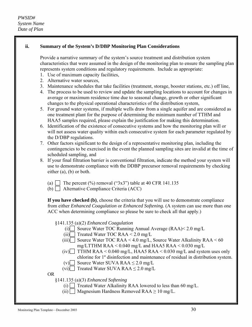
ii. Summary of the System’s D/DBP Monitoring Plan Considerations
Provide a narrative summary of the system’s source treatment and distribution system characteristics that were assumed in the design of the monitoring plan to ensure the sampling plan represents system conditions and regulatory requirements. Include as appropriate: 1. Use of maximum capacity facilities, 2. Alternative water sources, 3. Maintenance schedules that take facilities (treatment, storage, booster stations, etc.) off line, 4. The process to be used to review and update the sampling locations to account for changes in
average or maximum residence time due to seasonal change, growth or other significant changes to the physical operational characteristics of the distribution system,
5. For ground water systems, if multiple wells draw from a single aquifer and are considered as one treatment plant for the purpose of determining the minimum number of TTHM and HAA5 samples required, please explain the justification for making this determination.
6. Identification of the existence of consecutive systems and how the monitoring plan will or will not assess water quality within each consecutive system for each parameter regulated by the D/DBP regulations.
7. Other factors significant to the design of a representative monitoring plan, including the contingencies to be exercised in the event the planned sampling sites are invalid at the time of scheduled sampling, and
8. If your final filtration barrier is conventional filtration, indicate the method your system will use to demonstrate compliance with the DDBP precursor removal requirements by checking either (a), (b) or both.
(a) The percent (%) removal (“3x3”) table at 40 CFR 141.135 (b) Alternative Compliance Criteria (ACC)
If you have checked (b), choose the criteria that you will use to demonstrate compliance from either Enhanced Coagulation or Enhanced Softening. (A system can use more than one ACC when determining compliance so please be sure to check all that apply.)
§141.135 (a)(2) Enhanced Coagulation
(i) Source Water TOC Running Annual Average (RAA)< 2.0 mg/L (ii) Treated Water TOC RAA < 2.0 mg/L (iii) Source Water TOC RAA < 4.0 mg/L, Source Water Alkalinity RAA < 60
mg/LTTHM RAA < 0.040 mg/L and HAA5 RAA < 0.030 mg/L (iv) TTHM RAA < 0.040 mg/L, HAA5 RAA < 0.030 mg/L and system uses only
chlorine for 1º disinfection and maintenance of residual in distribution system. (v) Source Water SUVA RAA ≤ 2.0 mg/L (vi) Treated Water SUVA RAA ≤ 2.0 mg/L
OR §141.135 (a)(3) Enhanced Softening
(i) Treated Water Alkalinity RAA lowered to less than 60 mg/L. (ii) Magnesium Hardness Removed RAA ≥ 10 mg/L.

PWSID# System Name Date of Plan
Monitoring Plan Template—December 2003 31
iii. Summary of Monitoring Records Location and Maintenance
Disinfection Byproducts
Parameter Records Location Responsible Party
Name or Position Phone Number
TTHM/HAA5 Chlorite Bromate
Maximum Residual Disinfectant Level Parameter Records Location Responsible Party
Name or Position Phone Number
Total Chlorine Free Chlorine Combined Chlorine Chlorine Dioxide
Disinfection Byproducts Precursors (Conventional Filtration Only) Parameter Records Location Responsible Party
Name or Position Phone Number
TOC Source TOC Treated Alkalinity Source Bromide DOC Source UV254 Source DOC Finished UV254 Finished MgCO3 Source MgCO3 Finished Alkalinity Finished

PWSID# System Name Date of Plan
Monitoring Plan Template—December 2003 32
II. Disinfection Byproducts Monitoring
i. Paired TTHM/HAA5 Distribution System Monitoring 1. Complete for each paired TTHM/HAA5 distribution system (DS) sampling site:
Sample Site Location Identifier
Site Name
Site Address
Indicate whether this site represents DS maximum or average residence time
Maximum
Average
Maximum
Average
Maximum
Average
Maximum
Average
2. Show the location of each sampling point (by location identifier) on the distribution system
sketch in Part IV of your system’s monitoring plan. 3. Explain how any monitoring, including that in excess of minimum requirements, will be
scheduled so as to be representative of system conditions and how this data will be used to calculate compliance. This explanation should include information about the use of seasonal sources and/or treatment plants and how they will affect the systems TTHM and HAA5 sampling.
4. If any samples are associated with a consecutive system, explain how sampling points were selected to be representative of the entire service area and associated population served.

PWSID# System Name Date of Plan
Monitoring Plan Template—December 2003 33
ii. Chlorite Monitoring (for all systems using chlorine dioxide)
1. Show the location of each chlorite distribution system (DS) sampling site on the distribution
system schematic provided in Part IV of your system’s monitoring plan and provide here a list of all distribution system samples and their associated location identifiers:
Sampling Site Location Identifier
Sampling Site Name Sampling Site Address Indicate sample location (DS max. DS average or DS first customer )
DS Maximum DS Average DS First Customer
DS Maximum DS Average DS first Customer
DS Maximum DS Average DS First Customer
2. Explain how any monitoring, including that in excess of minimum requirements, will be
scheduled so as to be representative of system conditions and how this data will be used to calculate compliance.
3. Show the location of each chlorite entry point sampling location on the distribution system schematic provided in Part IV of your system’s monitoring plan and provide here a list of all entry point names and their associated location identifiers.
Entry Point Location Identifier
Entry Point Name
4. If any samples are associated with a consecutive or integrated system, explain how sampling
points were selected to be representative of the entire service area and associated population served.
5. Quality Assurance/Quality Control (QA/QC) – For each analytical test to be performed by a party approved by EPA, other than a certified laboratory, explain the exact QA/QC procedures to be followed to ensure that the analytical result will be accurate and representative of the water being sampled for each analysis performed.

PWSID# System Name Date of Plan
Monitoring Plan Template—December 2003 34
iii. Bromate Monitoring (for systems using Ozone):
1. Show the location of each bromate entry point sampling location on the distribution system
schematic provided in Part IV of your system’s monitoring plan and provide here a list of all entry point names and their associated location identifiers.
Entry Point Location Identifier
Entry Point Name
2. Explain how any monitoring, including that in excess of minimum requirements, will be
scheduled so as to be representative of system conditions and how this data will be used to calculate compliance.

PWSID# System Name Date of Plan
Monitoring Plan Template—December 2003 35
iv. Disinfection Byproduct Sample Analysis
1. Complete for each analyte tested (EP = entry point, DS = Distribution System):
Analyte Frequency (W/M/Q/A) Analytical Method
Indicate whether analyst is a Certified Laboratory or EPA Approved Party
TTHM Certified Laboratory
HAA5 Certified Laboratory
Chlorite* - EP Certified Laboratory EPA Approved Party
Chlorite* - DS Certified Laboratory Bromate** - EP Certified Laboratory
* Only systems using Chlorine Dioxide ** Only systems using Ozone
2. Quality Assurance/Quality Control (QA/QC) – For each analytical test to be performed by a party approved by EPA, other than a certified laboratory, explain the exact QA/QC procedures to be followed to ensure that the analytical result will be accurate and representative of the water being sampled.
3. Additional Information. (If appropriate to explain system characteristics) v. Disinfection Byproducts Reporting Forms
DBP Form 1 TTHM Analysis Laboratory Report Form DBP Form 2 HAA5 Analysis Laboratory Report Form DBP Form 3 TTHM and HAA5 Quarterly Report Worksheet (do not submit to EPA) DBP Form 4 Quarterly Reporting Form for Running Annual Average (RAA) for TTHMs and
HAA5s. DBP Form 5 Bromate and/or Chlorite Analysis Laboratory Report Form DBP Form 6 Quarterly Reporting Form for Running Annual Average (RAA) for Bromate – Only
for systems using Ozone. DBP Form 7 Quarterly Reporting Form for Daily, Monthly, and Additional Chlorite Monitoring –
Only for systems using Chlorine Dioxide in any process. DBP Form 8 Quarterly Reporting Form for Running Annual Average (RAA) for Bromide – Only
for systems using Ozone in any process.

PWSID# System Name Date of Plan
Monitoring Plan Template—December 2003 36
III. Maximum Residual Disinfectant Level (MRDL) Monitoring i. For Chlorine or Chloramine Monitoring
1. Complete for each chlorine residual/total coliform sampling site:
Site Location Identifier
Site Name Site Address
1. Show each sampling site (by location number) on the distribution system map in Part IV. 2. Explain how any monitoring, including that in excess of minimum requirements, will be
scheduled and located so as to be representative of system conditions and how this data will be used to calculate compliance.
3. Additional Information (If appropriate to explain system conditions) 4. Distinguish, if applicable, any chlorine sampling locations that are not associated with total
coliform monitoring. 5. Quality Assurance/Quality Control (QA/QC) – For each analytical test to be performed by a party
approved by EPA, other than a certified laboratory, explain the exact QA/QC procedures to be followed to ensure that the analytical result will be accurate and representative of the water being sampled for each analysis performed.

PWSID# System Name Date of Plan
Monitoring Plan Template—December 2003 37
ii. Chlorine Dioxide Monitoring
1. Show the location of each chlorine dioxide entry point sampling location on the distribution
system schematic provided in Part IV of your system’s monitoring plan and provide here a list of all entry point names and their associated location identifiers.
Entry Point Location Identifier
Entry Point Name
2. Complete for each distribution system (DS) monitoring location:
Site Location Identifier
Site Name
Site Address
Indicate sample location--(DS max., DS average, or DS first customer residence time)
DS Maximum DS Average DS First Customer
DS Maximum DS Average DS First Customer
DS Maximum DS Average DS First Customer
3. Explain how any monitoring, including that in excess of minimum requirements, will be
scheduled and located so as to be representative of system conditions and how this data will be used to calculate compliance.
4. Indicate whether disinfection booster stations exist within the distribution system. 5. Quality Assurance/Quality Control (QA/QC) – For each analytical test to be performed by a
party approved by EPA, other than a certified laboratory, explain the exact QA/QC procedures to be followed to ensure that the analytical result will be accurate and representative of the water being sampled for each analysis performed.

PWSID# System Name Date of Plan
Monitoring Plan Template—December 2003 38
iii. Disinfectant Residual Sample Analysis
1. Complete for each analyte tested (EP = Entry Point, DS = Distribution System):
Analyte Frequency (W/M/Q/A)
Analytical Method
Analysis Performed By: Indicate whether Certified Laboratory or EPA Approved Party
Total Chlorine Certified Laboratory EPA Approved Party Free Chlorine Certified Laboratory EPA Approved Party Combined Chlorine Certified Laboratory EPA Approved Party Chlorine Dioxide* (EP) Certified Laboratory EPA Approved Party Chlorine Dioxide* (DS) Certified Laboratory EPA Approved Party
*Only systems using chlorine dioxide as disinfectant or oxidant in their treatment process 2. Quality Assurance/Quality Control (QA/QC) – For each analytical test to be performed by a
party approved by EPA, other than a certified laboratory, explain the exact QA/QC procedures to be followed to ensure that the analytical result will be accurate and representative of the water being sampled.
iv. Disinfectant Residual Reporting Forms
MRDL Form 1 Chlorine and Chloramines, Maximum Residual Disinfectant Level (MRDL) Monthly Worksheet (do not submit to EPA)
MRDL Form 2 Quarterly Report Form for Chlorine and Chloramines Maximum Residual Disinfectant Level Running Annual Average (RAA)
MRDL Form 3 Quarterly Report Form for Daily Chlorine Dioxide

PWSID# System Name Date of Plan
Monitoring Plan Template—December 2003 39
IV. Disinfection Byproduct Precursors Monitoring i. Raw and Finished Water “Paired” Sampling Sites
1. Complete for each treatment plant:
Plant Name Plant ID Number *
Untreated Water Sample Location Identifier
Finished Sample Location Identifier
* Correlate the plant ID number with the identifier used by the EPA
2. Show each sampling point on the treatment plant schematic in Part III.
ii. “Paired” Sample Analysis for DBP Precursor Removal 1. Complete for each analysis used (D = daily, W = weekly, M = monthly, Q = quarterly, A =
annually); samples collected more frequently than the interval shown should be indicated with a number and letter. For example, if samples are taken 4 times a day, indicated as “4/D.”
Analysis Sampling Frequency (D/W/M/Q/A)
Analytical Method
Indicate whether a Certified Laboratory or a EPA Approved Party
TOC Source Certified Laboratory TOC Treated Certified Laboratory TOC Other (explain) Certified Laboratory
Total Alkalinity
Certified Laboratory
EPA Approved Party
DOC (alternative criteria) Certified Laboratory
UV-254 (alternative criteria)
Certified Laboratory
EPA Approved Party
Mg Hardness *
Certified Laboratory
EPA Approved Party
Bromide **
Certified Laboratory
EPA Approved Party
* Alternative criteria for softening systems ** Ozone systems applying for reduced monitoring only

PWSID# System Name Date of Plan
Monitoring Plan Template—December 2003 40
2. Explain how any monitoring, including that in excess of minimum requirements, will be
scheduled so as to be representative of system conditions and how this data will be used to calculate compliance.
3. With respect to paired TOC samples, explain whether the untreated and treated samples will be collected at virtually the same time or whether the detention time of the treatment process will be considered. In the event the detention time of the treatment process is to be considered, provide an explanation of the procedure to be used considering different possible plant operation configurations and flow rates.
4. Quality Assurance/Quality Control (QA/QC) – For each analytical test to be performed by a party approved by EPA, other than a certified laboratory, explain the exact QA/QC procedures to be followed to ensure that the analytical result will be accurate and representative of the water being sampled for each analysis performed.
5. Additional Information (Provide as appropriate to explain system characteristics)

PWSID# System Name Date of Plan
Monitoring Plan Template—December 2003 41
iii. Disinfection Byproduct Precursors Removal Reporting Forms:
DBP Precursor Form 1 Disinfectant Byproducts Precursors Laboratory Report to Public
Water System DBP Precursor Form 2 Alternative Compliance Criteria Disinfection Byproduct Precursor
Removal Compliance Reporting Form for Conventional Filtration Treatment Plants
DBP Precursor Form 3 Additional Alternative Compliance Criteria (for softening systems) Reporting Form
DBP Precursor Form 4 Disinfection Byproduct Precursor Removal – Quarterly Compliance Report Form for the Running Annual Average (RAA) – For Total Organic Carbon Removed

PWSID# System Name Date of Plan
Monitoring Plan Template—December 2003 42
Section B
Enhanced Surface Water Treatment Rules
(Including IESWTR and LT1ESWTR)
I. Treatment Requirements Summary i. Summary of Filtration Technology ii. Turbidimeter Calibration iii. Record Keeping
II. Combined Filter Effluent Turbidity Monitoring
III. Individual Filter Effluent Turbidity Monitoring
IV. Disinfectant Residual Entering the Distribution System
V. Disinfection Profile
VI. Additional Information

PWSID# System Name Date of Plan
Monitoring Plan Template—December 2003 43
I. Treatment Requirements Summary i. Describe the filtration technology used at each treatment plant
Treatment Plant Name Plant ID # Filtration Technology Conventional or Direct Filtration
Slow Sand Filtration Diatomaceous Earth Filtration Other Filtration Technologies*
Conventional or Direct Filtration Slow Sand Filtration Diatomaceous Earth Filtration Other Filtration Technologies*
Conventional or Direct Filtration Slow Sand Filtration Diatomaceous Earth Filtration Other Filtration Technologies*
* Provide a description of any “Other Filtration Technologies” that are being used.
ii. Turbidimeter Calibration
Meter Identification Filter Location Calibration Frequency
Frequency of Calibration Checks
Combined Individual Filter
Combined Individual Filter
Combined Individual Filter
Combined Individual Filter
Quality Assurance/Quality Control (QA/QC) – Explain the exact QA/QC procedures to be followed to ensure that the analytical result will be accurate.

PWSID# System Name Date of Plan
Monitoring Plan Template—December 2003 44
iii. Record Keeping
Please identify the physical location of the following records and the telephone number of the person responsible for their maintenance
Parameter Records Location Responsible Person Name or Position
Telephone Number
Turbidity Calibration
II. Combined Filter Effluent Turbidity Monitoring – Conventional and Direct Filtration Only Identify the sampling point and its designation and the times of the day that samples will be taken. Ensure there is no more than 4 hours between each sampling time. Treatment Plant Name Plant ID# Sample Point Description Sampling Times of Day
Mid-4 am 4 am-8 am 8 am-Noon Noon-4 pm 4pm-8 pm
8pm-Mid Mid-4 am 4 am-8 am 8 am-Noon Noon-4 pm 4pm-8 pm
8pm-Mid Mid-4 am 4 am-8 am 8 am-Noon Noon-4 pm 4pm-8 pm
8pm-Mid
PWSID# System Name Date of Plan
Monitoring Plan Template—December 2003 45
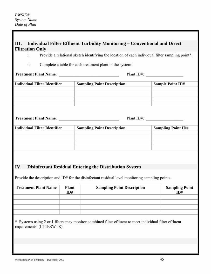
III. Individual Filter Effluent Turbidity Monitoring – Conventional and Direct Filtration Only
i. Provide a relational sketch identifying the location of each individual filter sampling point*. ii. Complete a table for each treatment plant in the system: Treatment Plant Name: _____________________________ Plant ID#: __________________ Individual Filter Identifier Sampling Point Description Sample Point ID# Treatment Plant Name: _____________________________ Plant ID#: __________________ Individual Filter Identifier Sampling Point Description Sampling Point ID#
IV. Disinfectant Residual Entering the Distribution System Provide the description and ID# for the disinfectant residual level monitoring sampling points. Treatment Plant Name Plant
ID# Sampling Point Description Sampling Point
ID# * Systems using 2 or 1 filters may monitor combined filter effluent to meet individual filter effluent requirements (LT1ESWTR).

PWSID# System Name Date of Plan
Monitoring Plan Template—December 2003 46
V. Disinfection Profile – Required for Those Systems Not Granted Exemption from EPA Region 8:
i. Provide a relational sketch of each point of disinfection and its sampling point. ii. For each point of disinfection complete the following:
a. Point of disinfection ID#: __________
Select Contactor Type
Rapid mix Flocculation basin Sedimentation basin Filter Clear Well or Storage
Tank Pipeline
Vessel Dimensions Length _________ Width __________ Depth __________ If circular tank or pipe: Diameter ________
Select Disinfectant Free Chlorine Chloramines Chlorine Dioxide
Applied Baffling Factor: __________
EPA Assigned Tracer Study
Sample point ID# representing this disinfection procedure: ___________
b. Point of disinfection ID#: ___________
Select Contactor Type Rapid mix Flocculation basin Sedimentation basin Filter Clear Well or Storage
Tank Pipeline
Vessel Dimensions Length _________ Width __________ Depth __________ If circular tank or pipe: Diameter ________
Select Disinfectant Free Chlorine Chloramines Chlorine Dioxide
Applied Baffling Factor: __________
EPA Assigned Tracer Study
Sample point ID# representing this disinfection procedure: ___________
PWSID# System Name Date of Plan
Monitoring Plan Template—December 2003 47
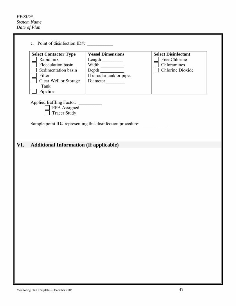
c. Point of disinfection ID#: ___________
Select Contactor Type
Rapid mix Flocculation basin Sedimentation basin Filter Clear Well or Storage
Tank Pipeline
Vessel Dimensions Length _________ Width __________ Depth __________ If circular tank or pipe: Diameter ________
Select Disinfectant Free Chlorine Chloramines Chlorine Dioxide
Applied Baffling Factor: __________
EPA Assigned Tracer Study
Sample point ID# representing this disinfection procedure: ___________
VI. Additional Information (If applicable)